WO2020121741A1 - Dispositif connecteur rotatif - Google Patents
Dispositif connecteur rotatif Download PDFInfo
- Publication number
- WO2020121741A1 WO2020121741A1 PCT/JP2019/045104 JP2019045104W WO2020121741A1 WO 2020121741 A1 WO2020121741 A1 WO 2020121741A1 JP 2019045104 W JP2019045104 W JP 2019045104W WO 2020121741 A1 WO2020121741 A1 WO 2020121741A1
- Authority
- WO
- WIPO (PCT)
- Prior art keywords
- wall
- connector device
- rotary connector
- stator
- maximum length
- Prior art date
- Legal status (The legal status is an assumption and is not a legal conclusion. Google has not performed a legal analysis and makes no representation as to the accuracy of the status listed.)
- Ceased
Links
Images






Classifications
-
- H—ELECTRICITY
- H01—ELECTRIC ELEMENTS
- H01R—ELECTRICALLY-CONDUCTIVE CONNECTIONS; STRUCTURAL ASSOCIATIONS OF A PLURALITY OF MUTUALLY-INSULATED ELECTRICAL CONNECTING ELEMENTS; COUPLING DEVICES; CURRENT COLLECTORS
- H01R35/00—Flexible or turnable line connectors, i.e. the rotation angle being limited
- H01R35/04—Turnable line connectors with limited rotation angle with frictional contact members
-
- B—PERFORMING OPERATIONS; TRANSPORTING
- B60—VEHICLES IN GENERAL
- B60R—VEHICLES, VEHICLE FITTINGS, OR VEHICLE PARTS, NOT OTHERWISE PROVIDED FOR
- B60R16/00—Electric or fluid circuits specially adapted for vehicles and not otherwise provided for; Arrangement of elements of electric or fluid circuits specially adapted for vehicles and not otherwise provided for
- B60R16/02—Electric or fluid circuits specially adapted for vehicles and not otherwise provided for; Arrangement of elements of electric or fluid circuits specially adapted for vehicles and not otherwise provided for electric constitutive elements
- B60R16/023—Electric or fluid circuits specially adapted for vehicles and not otherwise provided for; Arrangement of elements of electric or fluid circuits specially adapted for vehicles and not otherwise provided for electric constitutive elements for transmission of signals between vehicle parts or subsystems
- B60R16/027—Electric or fluid circuits specially adapted for vehicles and not otherwise provided for; Arrangement of elements of electric or fluid circuits specially adapted for vehicles and not otherwise provided for electric constitutive elements for transmission of signals between vehicle parts or subsystems between relatively movable parts of the vehicle, e.g. between steering wheel and column
-
- H—ELECTRICITY
- H01—ELECTRIC ELEMENTS
- H01R—ELECTRICALLY-CONDUCTIVE CONNECTIONS; STRUCTURAL ASSOCIATIONS OF A PLURALITY OF MUTUALLY-INSULATED ELECTRICAL CONNECTING ELEMENTS; COUPLING DEVICES; CURRENT COLLECTORS
- H01R13/00—Details of coupling devices of the kinds covered by groups H01R12/70 or H01R24/00 - H01R33/00
- H01R13/66—Structural association with built-in electrical component
-
- H—ELECTRICITY
- H01—ELECTRIC ELEMENTS
- H01R—ELECTRICALLY-CONDUCTIVE CONNECTIONS; STRUCTURAL ASSOCIATIONS OF A PLURALITY OF MUTUALLY-INSULATED ELECTRICAL CONNECTING ELEMENTS; COUPLING DEVICES; CURRENT COLLECTORS
- H01R13/00—Details of coupling devices of the kinds covered by groups H01R12/70 or H01R24/00 - H01R33/00
- H01R13/72—Means for accommodating flexible lead within the holder
-
- H—ELECTRICITY
- H02—GENERATION; CONVERSION OR DISTRIBUTION OF ELECTRIC POWER
- H02G—INSTALLATION OF ELECTRIC CABLES OR LINES, OR OF COMBINED OPTICAL AND ELECTRIC CABLES OR LINES
- H02G11/00—Arrangements of electric cables or lines between relatively-movable parts
-
- B—PERFORMING OPERATIONS; TRANSPORTING
- B62—LAND VEHICLES FOR TRAVELLING OTHERWISE THAN ON RAILS
- B62D—MOTOR VEHICLES; TRAILERS
- B62D1/00—Steering controls, i.e. means for initiating a change of direction of the vehicle
- B62D1/02—Steering controls, i.e. means for initiating a change of direction of the vehicle vehicle-mounted
- B62D1/04—Hand wheels
- B62D1/10—Hubs; Connecting hubs to steering columns, e.g. adjustable
-
- H—ELECTRICITY
- H01—ELECTRIC ELEMENTS
- H01R—ELECTRICALLY-CONDUCTIVE CONNECTIONS; STRUCTURAL ASSOCIATIONS OF A PLURALITY OF MUTUALLY-INSULATED ELECTRICAL CONNECTING ELEMENTS; COUPLING DEVICES; CURRENT COLLECTORS
- H01R2201/00—Connectors or connections adapted for particular applications
- H01R2201/26—Connectors or connections adapted for particular applications for vehicles
-
- H—ELECTRICITY
- H02—GENERATION; CONVERSION OR DISTRIBUTION OF ELECTRIC POWER
- H02G—INSTALLATION OF ELECTRIC CABLES OR LINES, OR OF COMBINED OPTICAL AND ELECTRIC CABLES OR LINES
- H02G11/00—Arrangements of electric cables or lines between relatively-movable parts
- H02G11/02—Arrangements of electric cables or lines between relatively-movable parts using take-up reel or drum
Definitions
- the technology disclosed in the present application relates to a rotary connector device.
- a rotary connector device used in a vehicle is known (for example, see Patent Document 1).
- the problem of the technology disclosed in this application is to improve the environment resistance of the rotary connector device.
- the rotary connector device includes a stator and a rotating body.
- the stator includes a first stator body and a second stator body that is a member separate from the first stator body and that is connected to the first stator body.
- the rotating body is provided rotatably around the rotation axis with respect to the stator.
- the stator and the rotating body define a cable accommodation space provided so as to surround the rotation axis between the stator and the rotating body.
- the second stator body includes a first wall extending along an axial direction parallel to the rotation axis and a second wall extending along the axial direction and spaced from the first wall in a radial direction perpendicular to the rotation axis. And a wall.
- the first wall is arranged between the cable housing space and the second wall in the radial direction.
- the first stator body includes an intermediate wall extending in the axial direction and arranged between the first wall and the second wall in the radial direction.
- the intermediate wall of the first stator body is arranged in the radial direction between the first wall and the second wall, the path from the outside of the stator to the cable housing space is long. Become. Therefore, foreign matter is less likely to enter the cable housing space from the outside of the stator, and the environment resistance of the rotary connector device can be improved.
- the rotary connector device according to the second feature is the rotary connector device according to the first feature, in which the intermediate wall extends along the axial direction.
- the first wall at least partially defines the cable housing space, it is possible to improve the environment resistance of the rotary connector device while suppressing an increase in size of the rotary connector device. it can.
- the rotary connector device according to the third feature is the rotary connector device according to the first or second feature, in which the first wall and the second wall are arranged outside the cable accommodation space in the radial direction.
- the rotary connector device since the first wall and the second wall are arranged outside the cable housing space in the radial direction, the environment resistance of the outer peripheral portion of the rotary connector device that is easily exposed to the outside is improved. Can be increased.
- a rotary connector device is the rotary connector device according to any one of the first to third features, wherein the first wall has a first maximum thickness defined in a radial direction and an axial direction. And a first maximum length. The first maximum length is greater than the first maximum thickness.
- the path from the outside of the stator to the cable accommodating space can be further lengthened.
- a rotary connector device is the rotary connector device according to any one of the first to fourth features, in which the second wall is defined in the radial direction with a second maximum thickness and in the axial direction. And a second maximum length. The second maximum length is greater than the second maximum thickness.
- the path from the outside of the stator to the cable accommodating space can be further lengthened.
- a rotary connector device is the rotary connector device according to any one of the first to fifth features, in which the intermediate wall has a third maximum thickness defined in the radial direction and an axial direction. And a third maximum length. The third maximum length is greater than the third maximum thickness.
- the path from the outside of the stator to the cable accommodating space can be further lengthened.
- a rotary connector device is the rotary connector device according to any one of the first to sixth features, in which the second stator body is provided between the first wall and the second wall in the radial direction. Includes an intermediate groove. The intermediate wall is arranged in the intermediate groove.
- the labyrinth structure can be formed in the path from the outside of the stator to the cable accommodation space.
- the rotary connector device is the rotary connector device according to the seventh feature, in which the second stator main body includes a connecting portion that connects the first wall to the second wall.
- the intermediate groove is defined by the first wall, the second wall, and the connecting portion.
- the intermediate groove is defined by the first wall, the second wall, and the connecting portion, so that the labyrinth structure is reliably formed in the path from the outside of the stator to the cable housing space. be able to.
- a rotary connector device is the rotary connector device according to any of the first to eighth features, wherein at least one of the first wall and the second wall is capable of contacting the intermediate wall in a radial direction. Is.
- At least one of the first wall and the second wall can contact the intermediate wall in the radial direction. Therefore, the path from the outside of the stator to the cable housing space can be narrowed, and the environment resistance of the rotary connector device can be further enhanced.
- a rotary connector device is the rotary connector device according to any one of the first to ninth features, wherein at least one of the first wall, the second wall, and the intermediate wall is provided around a rotation axis. It extends along the defined circumferential direction.
- At least one of the first wall, the second wall, and the intermediate wall extends along the circumferential direction defined around the rotation axis, so that the cable accommodation is performed from the outside of the stator. It is possible to secure a wide range in the circumferential direction in which the route to the space becomes long. Thereby, the environment resistance of the rotary connector device can be further enhanced.
- the rotary connector device according to the eleventh feature is the rotary connector device according to the tenth feature, wherein at least one of the first wall, the second wall, and the intermediate wall extends over 90 degrees or more in the circumferential direction. ..
- the path from the outside of the stator to the cable accommodation space is A long range can be surely secured in the circumferential direction.
- the rotary connector device according to the twelfth feature is the rotary connector device according to the eleventh feature, wherein at least one of the first wall, the second wall, and the intermediate wall extends over 180 degrees or more in the circumferential direction. ..
- the path from the outside of the stator to the cable accommodation space is A long range can be surely secured in the circumferential direction.
- a rotary connector device is the rotary connector device according to any one of the first to twelfth features, wherein the first stator body has a base plate that at least partially defines a cable accommodating space, and a shaft from the base plate.
- a coupling body extending in the radial direction and spaced apart from the intermediate wall in the radial direction.
- the second wall is arranged between the intermediate wall and the connecting body in the radial direction.
- the connection is made while extending the path from the outside of the second wall to the cable housing space.
- the connection strength of the body can be increased.
- the rotary connector device is the rotary connector device according to the thirteenth feature, in which the second stator main body includes a protrusion protruding radially outward from the second wall.
- the connecting body may contact the protrusion to connect the second stator body to the first stator body.
- the connecting body can contact the protrusion so as to connect the second stator body to the first stator body, the connection strength between the second stator body and the first stator body is further improved. Can be increased.
- the rotary connector device according to the fifteenth feature is the rotary connector device according to the thirteenth or fourteenth feature, wherein the second wall includes an outer peripheral surface and an outer concave portion provided on the outer peripheral surface.
- the connecting body is arranged in the outer recess.
- the connecting body is arranged in the outer recess, it is possible to increase the connecting strength between the first stator body and the second stator body while suppressing the increase in size of the stator.
- the rotary connector device according to the sixteenth feature is the rotary connector device according to the fifteenth feature, wherein the intermediate wall includes an intermediate outer peripheral surface and an intermediate recessed portion provided in the intermediate outer peripheral surface.
- the intermediate recess is arranged radially inward of the outer recess.
- the intermediate recess is arranged inside the outer recess in the radial direction, it is possible to lengthen the path from the outside of the stator to the cable accommodation space while suppressing the size increase of the stator.
- the rotary connector device according to the seventeenth feature is the rotary connector device according to the sixteenth feature, wherein the second wall includes a protruding portion disposed in the intermediate recess.
- the second wall since the second wall includes the protruding portion arranged in the intermediate recessed portion, the circumferential positioning of the first stator body and the second stator body becomes easy.
- a rotary connector device is the rotary connector device according to any of the first to fifteenth features, wherein the intermediate wall includes an intermediate outer peripheral surface and an intermediate recessed portion provided in the intermediate outer peripheral surface. I'm out.
- the second wall includes a protrusion located in the intermediate recess.
- the second wall since the second wall includes the protrusion arranged in the intermediate recess, the circumferential positioning of the first stator body and the second stator body becomes easy.
- a rotary connector device is the rotary connector device according to any one of the first to twelfth features, wherein the first stator body has an outer peripheral portion and at least partially defines a cable accommodating space. Is included.
- the intermediate wall extends from the outer peripheral portion of the base plate along the axial direction.
- the intermediate wall extends along the axial direction from the outer peripheral portion of the base plate, a wide cable accommodation space is ensured and a path from the outside of the stator to the cable accommodation space is long. it can.
- a rotary connector device is the rotary connector device according to any one of the first to nineteenth features, in which at least a part of the intermediate wall is located more than the rotation axis line when the stator is mounted on the vehicle body. It is placed on the upper side.
- the intermediate wall can reliably prevent the liquid from entering the cable housing space.
- the rotary connector device is the rotary connector device according to any of the first to twentieth features, wherein the first wall has a first maximum length defined in the axial direction.
- the second wall has a second maximum length that is axially defined.
- the intermediate wall has an axially defined third maximum length. At least one of the first maximum length and the second maximum length is longer than the third maximum length.
- the length of the gap between at least one of the first wall and the second wall and the intermediate wall can be secured longer.
- a rotary connector device is the rotary connector device according to any of the first to twenty-first features, in which the second stator body is provided between the first wall and the second wall in the radial direction. Includes an intermediate groove.
- the intermediate wall has an axially defined third maximum length.
- the intermediate groove has a fourth maximum length defined in the axial direction. The fourth maximum length is the same as the third maximum length or longer than the third maximum length.
- the length of the intermediate groove can be made longer.
- the environment resistance of the rotary connector device can be improved.
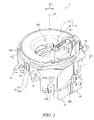
- FIG. 1 is a perspective view of the rotary connector device according to the first embodiment.
- FIG. 2 is an exploded perspective view of a rotary body of the rotary connector device shown in FIG.
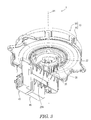
- FIG. 3 is another perspective view of the rotary connector device shown in FIG. 1.
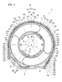
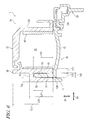
- FIG. 4 is a sectional view of the rotary connector device taken along line IV-IV in FIG.
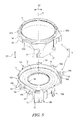
- FIG. 5 is an exploded perspective view of a stator of the rotary connector device shown in FIG. 1.
- FIG. 6 is a sectional view of the rotary connector device taken along line VI-VI in FIG.
- FIG. 7 is a partial perspective view of the rotary connector device shown in FIG.
- FIG. 8 is a sectional view of the rotary connector device taken along line VIII-VIII in FIG.
- FIG. 9 is another partial perspective view of the rotary connector device shown in FIG. 1.
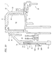
- FIG. 10 is a sectional view of the rotary connector device taken along line XX in FIG. 11 is a partial cross-sectional view of the rotary connector device shown in FIG. 12 is a partial perspective view of a second stator body of the stator shown in FIG.
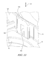
- FIG. 13 is a partial perspective view of a first stator body of the stator shown in FIG.
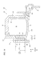
- FIG. 14 is a partial cross-sectional view of the rotary connector device according to the second embodiment (corresponding to FIG. 6).
- FIG. 15 is another partial cross-sectional view of the rotary connector device according to the second embodiment (corresponding to FIG. 8).
- FIG. 1 is a perspective view of a rotary connector device 1 according to the first embodiment.
- the rotary connector device 1 includes a stator 10 and a rotating body 20.
- the rotating body 20 is provided rotatably around the rotation axis A1 with respect to the stator 10.
- the stator 10 is configured to be fixed to the vehicle body
- the rotating body 20 is configured to be fixed to the steering wheel.
- the stator 10 includes a first stator body 11 and a second stator body 30.
- the second stator body 30 is a member separate from the first stator body 11, and is connected to the first stator body 11.
- the first stator body 11 is configured to be fixed to the vehicle body.
- FIG. 2 is an exploded perspective view of the rotary body 20 of the rotary connector device 1.
- the rotating body 20 includes a rotating plate 21, a tubular portion 22, a connector accommodating portion 24, and a sleeve 25.
- the rotary plate 21 has a substantially annular shape.
- the tubular portion 22 extends from the inner peripheral portion of the rotating plate 21 along the rotation axis A1 and includes a through hole 22A through which the steering shaft passes.
- the through hole 22A extends along the rotation axis A1.
- the sleeve 25 has an annular shape and is attached to the tubular portion 22.
- the connector housing portion 24 is provided on the rotating plate 21.
- a plurality of electric connectors connected to a plurality of electric devices for example, a horn switch and an airbag unit
- a plurality of electric devices for example, a horn switch and an airbag unit
- FIG. 3 is a perspective view of the rotary connector device 1.
- the rotary connector device 1 includes a stator electric connector 40 and a housing cover 45.
- the stator electrical connector 40 and the housing cover 45 are attached to the stator 10.
- the stator electric connector 40 is connected to an electric connector of an electric device (for example, a control device and a battery) provided in the vehicle body.
- an electric device for example, a control device and a battery
- FIG. 4 is a sectional view of the rotary connector device 1 taken along line IV-IV in FIG.
- the stator 10 and the rotating body 20 define a cable housing space 50 provided so as to surround the rotation axis A1 between the stator 10 and the rotating body 20.
- the cable housing space 50 is annular.
- the rotary connector device 1 includes an electric cable 60.
- the electric cable 60 is arranged in the cable housing space 50 and is electrically connected to the stator electric connector 40 (FIG. 2 ).
- the electric cable 60 is flexible and has a flat shape.
- the electric cable 60 is also called a flexible flat cable.
- FIG. 5 is an exploded perspective view of the stator 10 of the rotary connector device 1.
- the first stator body 11 includes a base plate 12.
- the base plate 12 includes an opening 12A and has an annular shape.
- the first stator body 11 includes a connector accommodating portion 13 and a plurality of fixing portions 14.
- the connector accommodating portion 13 extends from the base plate 12 along the axial direction D1 and accommodates an electric connector for heat steer, for example.
- the plurality of fixing portions 14 project outward from the base plate 12 in the radial direction.
- the fixing portion 14 is configured to be fixed to the vehicle body and has a fixing hole 14A.
- the first stator body 11 includes an intermediate wall 15.
- the intermediate wall 15 extends along the axial direction D1. Specifically, the intermediate wall 15 extends from the base plate 12 along the axial direction D1.
- FIG. 6 is a sectional view of the rotary connector device 1 taken along line VI-VI in FIG.
- the base plate 12 at least partially defines the cable receiving space 50.
- the base plate 12 has an outer peripheral portion 12B.
- the intermediate wall 15 extends from the outer peripheral portion 12B of the base plate 12 along the axial direction D1.
- the second stator body 30 includes a first wall 31 and a second wall 32.
- the first wall 31 extends along the axial direction D1 parallel to the rotation axis A1 and at least partially defines the cable housing space 50.
- the second wall 32 extends along the axial direction D1 and is spaced apart from the first wall 31 in the radial direction D2 that is perpendicular to the rotation axis A1.
- the first wall 31 is arranged between the cable housing space 50 and the second wall 32 in the radial direction D2.
- the first wall 31 and the second wall 32 are arranged outside the cable housing space 50 in the radial direction D2.
- the second wall 32 is arranged radially outside the first wall 31.
- the intermediate wall 15 is arranged between the first wall 31 and the second wall 32 in the radial direction D2.
- the second stator body 30 includes an intermediate groove 33 provided between the first wall 31 and the second wall 32 in the radial direction D2.
- the intermediate wall 15 is arranged in the intermediate groove 33.
- the second stator body 30 includes a connecting portion 34 that connects the first wall 31 to the second wall 32.
- the intermediate groove 33 is defined by the first wall 31, the second wall 32, and the connecting portion 34. At least one of the first wall 31 and the second wall 32 is capable of contacting the intermediate wall 15 in the radial direction D2. At least one of the first wall 31 and the second wall 32 can contact the base plate 12.
- the first wall 31 and the second wall 32 can contact the intermediate wall 15 in the radial direction D2.
- the first wall 31 and the second wall 32 are in contact with the base plate 12.
- the first wall 31, the second wall 32, and the base plate 12 position the first stator body 11 and the second stator body 30 in the axial direction D1.
- the intermediate wall 15 is separated from the connecting portion 34 in the axial direction D1.
- at least one of the first wall 31 and the second wall 32 may be in contact with the intermediate wall 15.
- At least one of the first wall 31 and the second wall 32 may be separated from the base plate 12 in the axial direction D1.
- a coupling structure such as an adhesive layer may be provided between the first wall 31 and the intermediate wall 15 and between the second wall 32 and the intermediate wall 15.
- the first wall 31 has a first maximum thickness T11 defined in the radial direction D2 and a first maximum length L11 defined in the axial direction D1.
- the first maximum length L11 is larger than the first maximum thickness T11.
- the second wall 32 has a second maximum thickness T21 defined in the radial direction D2 and a second maximum length L21 defined in the axial direction D1.
- the second maximum length L21 is larger than the second maximum thickness T21.
- the intermediate wall 15 has a third maximum thickness T31 defined in the radial direction D2 and a third maximum length L31 defined in the axial direction D1.
- the third maximum length L31 is larger than the third maximum thickness T31.
- the first maximum length L11 may be less than or equal to the first maximum thickness T11.
- the second maximum length L21 may be equal to or less than the second maximum thickness T21.
- the third maximum length L31 may be less than or equal to the third maximum thickness T31.
- At least one of the first maximum length L11 and the second maximum length L12 is longer than the third maximum length L13.
- the third maximum length L13 is longer than at least one of the first maximum thickness T11 and the second maximum thickness T11.
- the first maximum length L11 and the second maximum length L12 are longer than the third maximum length L13.
- the third maximum length L13 is longer than the first maximum thickness T11 and the second maximum thickness T11.
- these dimensional relationships are not limited to the dimensional relationships disclosed in FIG.
- the intermediate groove 33 has a fourth maximum length L41 defined in the axial direction D1.
- the fourth maximum length L41 is the same as the third maximum length L31 or longer than the third maximum length L31. In the present embodiment, the fourth maximum length L41 is longer than the third maximum length L31. However, the fourth maximum length L41 may be the same as the third maximum length L31.
- the intermediate groove 33 has a groove width T41 defined in the radial direction D2.
- the groove width T41 is equal to or larger than the third maximum thickness T31 of the intermediate wall 15.
- the groove width T41 is larger than the third maximum thickness T31 of the intermediate wall 15.
- the groove width T41 may be the same as the third maximum thickness T31 of the intermediate wall 15.
- the intermediate wall 15 is integrally provided with the base plate 12 as one single member.
- the intermediate wall 15 may be a separate member from the base plate 12.
- the first wall 31, the second wall 32, and the connecting portion 34 are integrally provided as one single member.
- at least one of the first wall 31, the second wall 32, and the connecting portion 34 may be a separate member from the other portions.
- At least one of the first wall 31, the second wall 32, and the intermediate wall 15 extends along the circumferential direction D3 defined around the rotation axis A1. At least one of the first wall 31, the second wall 32, and the intermediate wall 15 extends over 90 degrees or more in the circumferential direction D3. At least one of the first wall 31, the second wall 32, and the intermediate wall 15 extends over 180 degrees or more in the circumferential direction D3. In the present embodiment, the first wall 31, the second wall 32, and the intermediate wall 15 extend over 90 degrees or more in the circumferential direction D3. The first wall 31, the second wall 32, and the intermediate wall 15 extend over 180 degrees or more in the circumferential direction D3.
- first wall 31, the second wall 32, and the intermediate wall 15 may extend within the range of less than 180 degrees in the circumferential direction D3. At least one of the first wall 31, the second wall 32, and the intermediate wall 15 may extend within the range of less than 90 degrees in the circumferential direction D3. In addition, each of the first wall 31, the second wall 32, and the intermediate wall 15 extends continuously along the circumferential direction D3, but among the first wall 31, the second wall 32, and the intermediate wall 15, At least one may be intermittently provided in the circumferential direction D3.
- the intermediate wall 15 includes a first end 15A and a second end 15B.
- the intermediate wall 15 extends from the first end 15A to the second end 15B around the rotation axis A1.
- the first end portion 15A and the second end portion 15B define a circumferential range R1 around the rotation axis A1.
- the circumferential range R1 has a central angle of 90 degrees or more.
- the circumferential range R1 has a central angle of 180 degrees or more.
- the central angle of the circumferential range R1 is not limited to this embodiment.
- the intermediate wall 15 includes the curved portion 15C, the first flat plate portion 15D, and the second flat plate portion 15E.
- the curved portion 15C extends over 180 degrees or more in the circumferential direction D3.
- the first flat plate portion 15D linearly extends from the end portion of the curved portion 15C and has a first end portion 15A.
- the second flat plate portion 15E linearly extends from another end portion of the curved portion 15C and has a second end portion 15B.
- the intermediate groove 33 has a shape complementary to the intermediate wall 15 when viewed from the direction along the rotation axis A1.
- the curved portion 15C defines a circumferential range R2 around the rotation axis A1.
- the curved portion 15C extends in an arc shape around the rotation axis A1 in the circumferential range R2.
- the circumferential range R2 has a central angle of 90 degrees or more.
- the circumferential range R2 has a central angle of 180 degrees or more.
- the central angle of the circumferential range R2 is not limited to this embodiment.
- the first wall 31 includes a first end 31A and a second end 31B.
- the first wall 31 extends from the first end 31A to the second end 31B around the rotation axis A1.
- the first wall 31 includes the curved portion 31C, the first flat plate portion 31D, and the second flat plate portion 31E.
- the curved portion 31C extends over 180 degrees or more in the circumferential direction D3.
- the first flat plate portion 31D linearly extends from the end portion of the curved portion 31C and has a first end portion 31A.
- the second flat plate portion 31E linearly extends from another end portion of the curved portion 31C and has a second end portion 31B. Similar to the curved portion 15C of the intermediate wall 15, the curved portion 31C extends in an arc shape around the rotation axis A1 in the circumferential range R2.
- the second wall 32 includes a first end 32A and a second end 32B.
- the second wall 32 extends from the first end 32A to the second end 32B around the rotation axis A1.
- the second wall 32 includes the curved portion 32C, the first flat plate portion 32D, and the second flat plate portion 32E.
- the curved portion 32C extends over 180 degrees or more in the circumferential direction D3.
- the first flat plate portion 32D linearly extends from the end portion of the curved portion 32C and has a first end portion 32A.
- the second flat plate portion 32E extends linearly from another end portion of the curved portion 32C and has a second end portion 32B. Similar to the curved portion 15C of the intermediate wall 15, the curved portion 32C extends in an arc shape around the rotation axis A1 in the circumferential range R2.
- the second stator body 30 includes a third wall 35.
- the third wall 35 extends from the first wall 31 along the circumferential direction D3. More specifically, the third wall 35 extends from the first flat plate portion 31D toward the second flat plate portion 31E along the circumferential direction D3.
- the third wall 35 is arranged so as to be spaced apart from the second flat plate portion 31E.
- the third wall 35 partially defines the cable housing space 50.
- the second stator body 30 includes a cable passage 36.
- the cable passage 36 is connected to the cable housing space 50.
- the electric cable 60 is drawn from the cable housing space 50 to the outside of the cable housing space 50 through the cable passage 36.
- the cable passage 36 includes a first passage 36A and a second passage 36B.
- the first passage 36A extends from the cable housing space 50 along the second flat plate portion 31E of the first wall 31.
- the second passage 36B extends from the first passage 36A along the outer periphery of the cable housing space 50 toward the first flat plate portion 31D of the first wall 31.
- the cable passage 36 is arranged between the first flat plate portion 15D and the second flat plate portion 15E of the intermediate wall 15.
- the vertical direction in FIG. 4 is substantially the same as the vertical direction of the stator 10 when the stator 10 is mounted on the vehicle body.
- the stator 10 is mounted on the vehicle body, at least a part of the intermediate wall 15 is arranged above the rotation axis A1.
- part of the intermediate wall 15 is arranged at the uppermost part of the stator 10.
- the intermediate wall 15 is arranged over the entire region above the rotation axis A1.
- the second stator main body 30 includes a cover portion 37.
- the cover portion 37 partially covers the connector accommodating portion 13 in a state where the second stator body 30 is connected to the first stator body 11.
- the cover portion 37 includes the first end portion 31A of the first wall 31 and the first end portion 32A of the second wall 32 to the second end portion 31B of the first wall 31 and the second end portion 32B of the second wall 32. It extends along the circumferential direction D3 to the second end 32B.
- the cover portion 37 connects the first end portion 31A of the first wall 31 and the first end portion 32A of the second wall 32 to the second end portion 31B of the first wall 31 and the second end portion 32B of the second wall 32. ing.
- the cover portion 37 is connected to the third wall 35.
- the cable passage 36 is defined between the first wall 31, the third wall 35, and the cover portion 37.
- the first stator main body 11 includes a connecting body 16A.
- the connecting body 16A extends from the base plate 12 along the axial direction D1.
- the connecting body 16A connects the second stator body 30 to the first stator body 11.
- the first stator body 11 includes a plurality of connecting bodies 16A.
- the plurality of connecting bodies 16A are arranged at intervals in the circumferential direction D3.
- the plurality of connecting bodies 16A are arranged at substantially the same position in the axial direction D1.
- the plurality of connecting bodies 16A are arranged radially outside the intermediate wall 15.
- the total number and arrangement of the connecting bodies 16A are not limited to this embodiment. At least one of the plurality of connecting bodies 16A may be omitted from the first stator body 11.
- the first stator body 11 includes an additional connecting body 16B.
- the additional connecting body 16B is arranged at a position displaced from the connecting body 16A in the axial direction D1.
- the additional connection body 16B is arranged between the first end portion 15A and the second end portion 15B of the intermediate wall 15 and at a position displaced from the first end portion 15A and the second end portion 15B in the axial direction D1.
- the first stator body 11 includes a plurality of additional connecting bodies 16B.
- the total number of the additional connecting bodies 16B is not limited to this embodiment. At least one of the plurality of additional connecting bodies 16B may be omitted from the first stator body 11.
- FIG. 7 is a partial perspective view of the rotary connector device 1.
- the connecting body 16A includes a connecting groove 16C.
- the connecting groove 16C extends along the axial direction D1.
- the shape of the connecting body 16A is not limited to this embodiment.
- FIG. 8 is a sectional view of the rotary connector device 1 taken along the line VIII-VIII in FIG.
- the connecting body 16A is arranged at a distance from the intermediate wall 15 in the radial direction D2.
- the second wall 32 is arranged between the intermediate wall 15 and the connecting body 16A in the radial direction D2.
- the second stator body 30 includes a protrusion 38A.
- the protrusion 38A projects radially outward from the second wall 32.
- the connecting body 16A is capable of contacting the protrusion 38A so as to connect the second stator body 30 to the first stator body 11.
- the protrusion 38A is arranged in the connecting groove 16C in a state where the second stator body 30 is connected to the first stator body 11.
- the second stator main body 30 includes a plurality of protrusions 38A.
- the total number of protrusions 38A is the same as the total number of connected bodies 16A.
- the total number of the protrusions 38A is not limited to this embodiment.
- FIG. 9 is a partial perspective view of the rotary connector device 1.
- the additional connecting body 16B includes an additional connecting groove 16D.
- the additional connection groove 16D extends along the axial direction D1.
- the shape of the additional connecting body 16B is not limited to this embodiment.
- FIG. 10 is a sectional view of the rotary connector device 1 taken along line XX in FIG.
- the second stator body 30 includes an additional protrusion 38B.
- the additional protrusion 38B projects outward from the cover portion 37 in the radial direction D2.
- the additional connection body 16B can contact the additional protrusion 38B so as to connect the second stator body 30 to the first stator body 11.
- the additional protrusion 38B is arranged in the additional connection groove 16D while the second stator body 30 is connected to the first stator body 11.
- the second stator main body 30 includes a plurality of additional protrusions 38B.
- the total number of the additional protrusions 38B is not limited to this embodiment. At least one of the plurality of additional protrusions 38B may be omitted from the second stator body 30.
- FIG. 11 is a partial sectional view of the rotary connector device 1.
- FIG. 12 is a partial perspective view of the second stator body 30 of the stator 10.
- the second wall 32 includes an outer peripheral surface 32F and an outer recess 32G.
- the outer recess 32G is provided on the outer peripheral surface 32F.
- the connecting body 16A is arranged in the outer recess 32G.
- the protrusion 38A is arranged in the outer recess 32G.
- the outer recess 32G extends along the axial direction D1.
- the second wall 32 includes a plurality of outer recesses 32G.
- the plurality of connecting bodies 16A are arranged in the plurality of outer recesses 32G, respectively.
- the total number of the outer recesses 32G is not limited to this embodiment. At least one of the plurality of outer recesses 32G may be omitted from the second wall 32.
- FIG. 13 is a partial perspective view of the first stator body 11 of the stator 10.
- the intermediate wall 15 includes an intermediate outer peripheral surface 15F and an intermediate recess 15G.
- the intermediate recess 15G is provided on the intermediate outer peripheral surface 15F.
- the intermediate recess 15G extends from the base plate 12 along the axial direction D1.
- the second wall 32 includes a protrusion 32H arranged in the intermediate recess 15G.
- the second wall 32 includes an inner peripheral surface 32K.
- the projecting portion 32H projects radially inward from the inner peripheral surface 32K.
- the inner peripheral surface 32K of the second wall 32 faces the intermediate outer peripheral surface 15F.
- the intermediate recess 15G is arranged radially inward of the outer recess 32G.
- the position of the intermediate recess 15G is substantially the same as the position of the outer recess 32G in the circumferential direction D3.
- the outer recess 32G has a first circumferential length CL1 defined in the circumferential direction D3.
- the intermediate recess 15G has a second circumferential length CL2 defined in the circumferential direction D3.
- the connecting body 16A has a third circumferential length CL3 defined in the circumferential direction D3.
- the protrusion 32H has a fourth circumferential length CL4 defined in the circumferential direction D3.
- the second circumferential direction length CL2 is longer than the first circumferential direction length CL1, the third circumferential direction length CL3, and the fourth circumferential direction length CL4.
- the fourth circumferential direction length CL4 is longer than the first circumferential direction length CL1 and the third circumferential direction length CL3.
- the first circumferential direction length CL1 is longer than the third circumferential direction length CL3.
- the dimensional relationship between the first to fourth circumferential lengths CL1 to CL4 is not limited to this embodiment.
- the positional relationship between the intermediate recess 15G and the outer recess 32G is not limited to this embodiment.
- the intermediate wall 15 includes a plurality of intermediate recesses 15G.
- the second wall 32 includes a plurality of protrusions 32H.
- the plurality of protrusions 32H are respectively arranged in the plurality of intermediate recesses 15G.
- the total number of intermediate concave portions 15G is the same as the total number of connected bodies 16A. However, the total number of the intermediate concave portions 15G and the protruding portions 32H is not limited to this embodiment.
- the intermediate wall 15 has a thickness T22 defined in the radial direction D2.
- the thickness T22 is defined within the range of the intermediate recess 15G.
- the thickness T22 is smaller than the second maximum thickness T21 (FIG. 6).
- the second wall 32 has a thickness T32 defined in the radial direction D2.
- the thickness T32 is defined within the outer recess 32G.
- the thickness T32 is smaller than the third maximum thickness T31 (FIG. 6).
- the thickness T32 is smaller than the thickness T22.
- the dimensional relationship between the thicknesses T22 and T32 is not limited to this embodiment.
- the first stator main body 11 includes an intermediate wall 17.
- the connector accommodating portion 13 includes the intermediate wall 17.
- the intermediate wall 17 extends along the axial direction D1.
- the second stator body 30 includes a first wall 71 and a second wall 72.
- the cover portion 37 includes the first wall 71 and the second wall 72.
- the first wall 71 extends along the axial direction D1 and at least partially defines the connector housing space 80.
- the connector housing space 80 is connected to the cable passage 36.
- the second wall 72 extends along the axial direction D1 and is spaced apart from the first wall 71 in the radial direction D2.
- the second wall 72 is arranged radially outside the first wall 71.
- the intermediate wall 17 is arranged between the first wall 71 and the second wall 72 in the radial direction D2.
- the second stator body 30 includes an intermediate groove 73 provided between the first wall 71 and the second wall 72 in the radial direction D2.
- the intermediate wall 17 is arranged in the intermediate groove 73.
- the second stator body 30 includes a connecting portion 74 that connects the first wall 71 to the second wall 72.
- the intermediate groove 73 is defined by the first wall 71, the second wall 72, and the connecting portion 74. At least one of the first wall 71 and the second wall 72 can contact the intermediate wall 17 in the radial direction D2. In the present embodiment, the first wall 71 and the second wall 72 can contact the intermediate wall 17 in the radial direction D2.
- a bonding structure such as an adhesive layer may be provided between the first wall 71 and the intermediate wall 17 and between the second wall 72 and the intermediate wall 17.
- the additional connecting body 16B is connected to the intermediate wall 17.
- the additional protrusion 38B projects radially outward from the second wall 72.
- the intermediate wall 17, the first wall 71, and the second wall 72 have substantially the same structure as the intermediate wall 15, the first wall 31, and the second wall 32. Therefore, detailed description of the intermediate wall 17, the first wall 71, and the second wall 72 is omitted.
- the features of the rotary connector device 1 are as follows. (1) As shown in FIG. 6, in the rotary connector device 1, since the intermediate wall 15 of the first stator body 11 is arranged between the first wall 31 and the second wall 32 in the radial direction D2, the stator 10 The path from the outside to the cable housing space 50 becomes longer. Therefore, foreign matter is less likely to enter the cable housing space 50 from the outside of the stator 10, and the environment resistance of the rotary connector device 1 can be improved. (2) As shown in FIG. 6, since the first wall 31 at least partially defines the cable housing space 50, it is possible to prevent the rotary connector device 1 from increasing in size while maintaining the environment resistance of the rotary connector device 1. Can be increased. (3) As shown in FIG.
- the first wall 31 and the second wall 32 are arranged outside the cable housing space 50 in the radial direction D2, so that the outer peripheral portion of the rotary connector device 1 that is easily exposed to the outside.
- the environment resistance can be improved.
- the first maximum length L11 is larger than the first maximum thickness T11, the path from the outside of the stator 10 to the cable housing space 50 can be further lengthened.
- the second maximum length L21 is larger than the second maximum thickness T21, the path from the outside of the stator 10 to the cable housing space 50 can be further lengthened.
- the first maximum length L11 is larger than the first maximum thickness T11
- the path from the outside of the stator 10 to the cable housing space 50 can be further lengthened.
- the second maximum length L21 is larger than the second maximum thickness T21, the path from the outside of the stator 10 to the cable housing space 50 can be further lengthened.
- the path from the outside of the stator 10 to the cable housing space 50 can be further lengthened.
- the intermediate wall 15 is arranged in the intermediate groove 33, a labyrinth structure can be formed in the path from the outside of the stator 10 to the cable housing space 50.
- the intermediate groove 33 is defined by the first wall 31, the second wall 32, and the connecting portion 34, the labyrinth structure is provided in the path from the outside of the stator 10 to the cable housing space 50. Can be reliably formed.
- at least one of the first wall 31 and the second wall 32 can contact the intermediate wall 15 in the radial direction D2.
- the path from the outside of the stator 10 to the cable housing space 50 can be narrowed, and the environment resistance of the rotary connector device 1 can be further enhanced.
- the stator 10 As shown in FIG. 4, since at least one of the first wall 31, the second wall 32, and the intermediate wall 15 extends along the circumferential direction D3 defined around the rotation axis A1, the stator 10 It is possible to secure a wide range in the circumferential direction D3 in which the path from the outside to the cable housing space 50 is long. Thereby, the environment resistance of the rotary connector device 1 can be further enhanced.
- (11) As shown in FIG.
- connection strength of the connection body 16A since the second wall 32 is arranged between the intermediate wall 15 and the connecting body 16A in the radial direction D2, the path from the outside of the second wall 32 to the cable housing space 50 is It is possible to increase the connection strength of the connection body 16A while increasing the length.
- the connecting body 16A can contact the protrusion 38A so as to connect the second stator body 30 to the first stator body 11, the second stator body 30 and the first stator body 11 are connected. The connection strength of can be further increased.
- the connecting body 16A is arranged in the outer recess 32G, the connecting strength between the first stator body 11 and the second stator body 30 is increased while suppressing the size increase of the stator 10. be able to.
- the intermediate recessed portion 15G is arranged radially inward of the outer recessed portion 32G, the path from the outside of the stator 10 to the cable housing space 50 is suppressed while suppressing the size increase of the stator 10. Can be long.
- the second wall 32 includes the protrusion 32H arranged in the intermediate recess 15G, the first stator body 11 and the second stator body 30 can be positioned in the circumferential direction D3. It will be easy.
- the intermediate wall 15 extends from the outer peripheral portion 12B of the base plate 12 along the axial direction D1, the cable housing space 50 is secured from the outside of the stator 10 while ensuring a wide cable housing space 50.
- the route up to 50 can be lengthened.
- the fourth maximum length L41 is equal to or longer than the third maximum length L31, so that the length of the intermediate groove 33 can be secured longer.
- a rotary connector device 201 according to the second embodiment will be described with reference to FIGS. 14 and 15.
- the rotary connector device 201 has the same structure as the rotary connector device 201 except for the first stator body and the second stator body. Therefore, in this specification, for simplification of description, elements having substantially the same functions as those described in the first embodiment are denoted by the same reference numerals, and the description thereof will be omitted.
- FIG. 14 is a partial cross-sectional view of the rotary connector device 201 according to the second embodiment and corresponds to FIG. 6 of the first embodiment.
- FIG. 15 is another partial sectional view of the rotary connector device 201, and corresponds to FIG. 8 of the first embodiment.
- the rotary connector device 201 includes a stator 210 and a rotary body 20.
- the stator 210 includes a first stator body 211 and a second stator body 230.
- the second stator main body 230 is a member separate from the first stator main body 211, and is connected to the first stator main body 211.
- the stator 210 has substantially the same structure as the stator 10 of the first embodiment. In this embodiment, the positional relationship between the first stator body 211 and the second stator body 230 is replaced with the positional relationship between the first stator body 11 and the second stator body 30 of the first embodiment.
- the first stator body 211 includes the intermediate wall 15.
- the second stator body 230 includes a first wall 31 and a second wall 32.
- the second stator body 230 includes the base plate 12.
- the first wall 31 and the second wall 32 extend from the outer peripheral portion 12B of the base plate 12 along the axial direction D1.
- first wall 31 and the second wall 32 are provided integrally with the base plate 12 as one single member. However, at least one of the first wall 31 and the second wall 32 may be a member separate from the base plate 12.
- the rotary connector device 201 can obtain substantially the same effect as the rotary connector device 1 of the first embodiment.
- ordinal numbers such as “first” and “second” are merely terms for identifying the configuration and do not have any other meaning (for example, a specific order).
- first element does not imply the existence of the "second element”
- second element does not mean the “first element”. It does not imply that "elements” are present.
- the expression “at least one of A and B” in the present disclosure includes, for example, (1) only A, (2) only B, and (3) both A and B. .
- the expression “at least one of A, B and C” means, for example, (1) A only, (2) B only, (3) C only, (4) A and B, (5) B and C, (6) A and C, and (7) all of A, B and C are included.
- the phrase "at least one of A and B" is not to be construed as "at least one of A and at least one of B.”
Landscapes
- Engineering & Computer Science (AREA)
- Mechanical Engineering (AREA)
- Motor Or Generator Frames (AREA)
- Steering Controls (AREA)
- Electric Cable Arrangement Between Relatively Moving Parts (AREA)
- Details Of Connecting Devices For Male And Female Coupling (AREA)
Abstract
Priority Applications (5)
| Application Number | Priority Date | Filing Date | Title |
|---|---|---|---|
| EP19896917.2A EP3896803B1 (fr) | 2018-12-13 | 2019-11-18 | Dispositif connecteur rotatif |
| KR1020217021151A KR102759872B1 (ko) | 2018-12-13 | 2019-11-18 | 회전 커넥터 장치 |
| CN201980079448.8A CN113261164B (zh) | 2018-12-13 | 2019-11-18 | 旋转连接器装置 |
| JP2020559876A JP7371010B2 (ja) | 2018-12-13 | 2019-11-18 | 回転コネクタ装置 |
| US17/330,413 US11901683B2 (en) | 2018-12-13 | 2021-05-26 | Rotary connector device |
Applications Claiming Priority (2)
| Application Number | Priority Date | Filing Date | Title |
|---|---|---|---|
| JP2018233783 | 2018-12-13 | ||
| JP2018-233783 | 2018-12-13 |
Related Child Applications (1)
| Application Number | Title | Priority Date | Filing Date |
|---|---|---|---|
| US17/330,413 Continuation US11901683B2 (en) | 2018-12-13 | 2021-05-26 | Rotary connector device |
Publications (1)
| Publication Number | Publication Date |
|---|---|
| WO2020121741A1 true WO2020121741A1 (fr) | 2020-06-18 |
Family
ID=71076304
Family Applications (1)
| Application Number | Title | Priority Date | Filing Date |
|---|---|---|---|
| PCT/JP2019/045104 Ceased WO2020121741A1 (fr) | 2018-12-13 | 2019-11-18 | Dispositif connecteur rotatif |
Country Status (6)
| Country | Link |
|---|---|
| US (1) | US11901683B2 (fr) |
| EP (1) | EP3896803B1 (fr) |
| JP (1) | JP7371010B2 (fr) |
| KR (1) | KR102759872B1 (fr) |
| CN (1) | CN113261164B (fr) |
| WO (1) | WO2020121741A1 (fr) |
Citations (5)
| Publication number | Priority date | Publication date | Assignee | Title |
|---|---|---|---|---|
| JP3408922B2 (ja) * | 1996-05-24 | 2003-05-19 | アルプス電気株式会社 | 回転コネクタ |
| JP2004222369A (ja) | 2003-01-10 | 2004-08-05 | Furukawa Electric Co Ltd:The | 回転コネクタ装置 |
| JP2013020850A (ja) * | 2011-07-12 | 2013-01-31 | Niles Co Ltd | 回転コネクタ装置 |
| JP2013157209A (ja) * | 2012-01-30 | 2013-08-15 | Niles Co Ltd | 回転コネクタ装置 |
| WO2017170752A1 (fr) * | 2016-03-31 | 2017-10-05 | 古河電気工業株式会社 | Dispositif de connecteur rotatif |
Family Cites Families (21)
| Publication number | Priority date | Publication date | Assignee | Title |
|---|---|---|---|---|
| US5674082A (en) * | 1995-02-21 | 1997-10-07 | Niles Parts Co., Ltd. | Rotary connector device |
| US7104821B2 (en) * | 2004-09-16 | 2006-09-12 | Alps Electric Co., Ltd. | Rotary connector |
| JP4602176B2 (ja) | 2005-07-01 | 2010-12-22 | 矢崎総業株式会社 | 回転コネクタ装置 |
| JP2008007075A (ja) * | 2006-06-30 | 2008-01-17 | Yazaki Corp | 舵角センサ組み込み式回転コネクタ装置 |
| JP5097364B2 (ja) * | 2006-06-30 | 2012-12-12 | 矢崎総業株式会社 | 舵角センサ組み込み式回転コネクタ装置 |
| JP2008021555A (ja) * | 2006-07-13 | 2008-01-31 | Alps Electric Co Ltd | 回転コネクタ |
| JP5259265B2 (ja) * | 2008-06-19 | 2013-08-07 | ナイルス株式会社 | 回転コネクタ装置 |
| JP5241016B2 (ja) * | 2009-01-29 | 2013-07-17 | 矢崎総業株式会社 | 回転コネクタ |
| JP5117528B2 (ja) * | 2010-03-30 | 2013-01-16 | 古河電気工業株式会社 | 回転コネクタ装置 |
| JP5224404B2 (ja) * | 2010-03-30 | 2013-07-03 | 古河電気工業株式会社 | 回転コネクタ装置 |
| JP5117529B2 (ja) * | 2010-03-30 | 2013-01-16 | 古河電気工業株式会社 | 回転コネクタ装置 |
| JP5019662B2 (ja) * | 2010-09-27 | 2012-09-05 | 古河電気工業株式会社 | 回転コネクタ装置 |
| JP4974195B2 (ja) * | 2010-10-20 | 2012-07-11 | 古河電気工業株式会社 | 回転コネクタ装置 |
| JP5184716B2 (ja) * | 2010-11-19 | 2013-04-17 | 古河電気工業株式会社 | 回転コネクタ装置 |
| EP2685571B1 (fr) * | 2011-03-09 | 2017-05-03 | Furukawa Electric Co., Ltd. | Dispositif de connexion rotatif |
| JP4974196B1 (ja) * | 2011-09-29 | 2012-07-11 | 古河電気工業株式会社 | 回転コネクタ装置 |
| JP5886148B2 (ja) * | 2012-06-21 | 2016-03-16 | 株式会社ヴァレオジャパン | 回転コネクタ装置 |
| KR101591320B1 (ko) * | 2013-01-15 | 2016-02-03 | 후루카와 덴키 고교 가부시키가이샤 | 센서 장착 회전 커넥터 |
| JP6754377B2 (ja) * | 2016-01-08 | 2020-09-09 | 古河電気工業株式会社 | 回転コネクタ装置 |
| WO2017170650A1 (fr) * | 2016-03-31 | 2017-10-05 | 古河電気工業株式会社 | Dispositif de raccordement rotatif |
| KR102241323B1 (ko) * | 2017-02-10 | 2021-04-16 | 후루카와 덴키 고교 가부시키가이샤 | 회전 커넥터 장치 |
-
2019
- 2019-11-18 JP JP2020559876A patent/JP7371010B2/ja active Active
- 2019-11-18 CN CN201980079448.8A patent/CN113261164B/zh active Active
- 2019-11-18 EP EP19896917.2A patent/EP3896803B1/fr active Active
- 2019-11-18 KR KR1020217021151A patent/KR102759872B1/ko active Active
- 2019-11-18 WO PCT/JP2019/045104 patent/WO2020121741A1/fr not_active Ceased
-
2021
- 2021-05-26 US US17/330,413 patent/US11901683B2/en active Active
Patent Citations (5)
| Publication number | Priority date | Publication date | Assignee | Title |
|---|---|---|---|---|
| JP3408922B2 (ja) * | 1996-05-24 | 2003-05-19 | アルプス電気株式会社 | 回転コネクタ |
| JP2004222369A (ja) | 2003-01-10 | 2004-08-05 | Furukawa Electric Co Ltd:The | 回転コネクタ装置 |
| JP2013020850A (ja) * | 2011-07-12 | 2013-01-31 | Niles Co Ltd | 回転コネクタ装置 |
| JP2013157209A (ja) * | 2012-01-30 | 2013-08-15 | Niles Co Ltd | 回転コネクタ装置 |
| WO2017170752A1 (fr) * | 2016-03-31 | 2017-10-05 | 古河電気工業株式会社 | Dispositif de connecteur rotatif |
Non-Patent Citations (1)
| Title |
|---|
| See also references of EP3896803A4 |
Also Published As
| Publication number | Publication date |
|---|---|
| US20210281033A1 (en) | 2021-09-09 |
| EP3896803A4 (fr) | 2022-01-26 |
| CN113261164A (zh) | 2021-08-13 |
| EP3896803A1 (fr) | 2021-10-20 |
| KR102759872B1 (ko) | 2025-02-03 |
| KR20210098529A (ko) | 2021-08-10 |
| JPWO2020121741A1 (ja) | 2021-10-28 |
| CN113261164B (zh) | 2024-05-28 |
| JP7371010B2 (ja) | 2023-10-30 |
| EP3896803B1 (fr) | 2025-06-25 |
| US11901683B2 (en) | 2024-02-13 |
Similar Documents
| Publication | Publication Date | Title |
|---|---|---|
| JP6578642B2 (ja) | モータ | |
| US20170324300A1 (en) | Motor | |
| US20180115224A1 (en) | Motor | |
| JP6520033B2 (ja) | モータ | |
| JP6164203B2 (ja) | モータ | |
| US10734861B2 (en) | Motor | |
| WO2019065007A1 (fr) | Actionneur à commande électrique | |
| JP6672395B2 (ja) | 温度センサの取付構造 | |
| JP2020054149A (ja) | モータ | |
| JP7426930B2 (ja) | 回転コネクタ装置および回転コネクタ装置の回転体 | |
| JP7371010B2 (ja) | 回転コネクタ装置 | |
| US11060931B2 (en) | Sensor device | |
| CN108352756B (zh) | 电动机 | |
| EP3863129B1 (fr) | Dispositif connecteur rotatif | |
| US11444422B2 (en) | Rotary connector device and fixed body of rotary connector device | |
| KR102764883B1 (ko) | 회전 커넥터 장치 | |
| JP7050645B2 (ja) | センサ | |
| US11843210B2 (en) | Rotary connector device | |
| WO2025052990A1 (fr) | Capteur d'angle | |
| US20230318391A1 (en) | Motor unit | |
| WO2025052991A1 (fr) | Dispositif rotatif | |
| JP2025086090A (ja) | 回転コネクタ装置 | |
| JP2025095779A (ja) | 回転コネクタ装置 | |
| WO2026088743A1 (fr) | Capteur d'angle | |
| JP2016195498A (ja) | レゾルバのワイヤハーネス保持構造 |
Legal Events
| Date | Code | Title | Description |
|---|---|---|---|
| 121 | Ep: the epo has been informed by wipo that ep was designated in this application |
Ref document number: 19896917 Country of ref document: EP Kind code of ref document: A1 |
|
| ENP | Entry into the national phase |
Ref document number: 2020559876 Country of ref document: JP Kind code of ref document: A |
|
| NENP | Non-entry into the national phase |
Ref country code: DE |
|
| ENP | Entry into the national phase |
Ref document number: 20217021151 Country of ref document: KR Kind code of ref document: A |
|
| ENP | Entry into the national phase |
Ref document number: 2019896917 Country of ref document: EP Effective date: 20210713 |
|
| WWG | Wipo information: grant in national office |
Ref document number: 2019896917 Country of ref document: EP |