WO2020121769A1 - Connecteur optique, câble optique et dispositif électronique - Google Patents
Connecteur optique, câble optique et dispositif électronique Download PDFInfo
- Publication number
- WO2020121769A1 WO2020121769A1 PCT/JP2019/045586 JP2019045586W WO2020121769A1 WO 2020121769 A1 WO2020121769 A1 WO 2020121769A1 JP 2019045586 W JP2019045586 W JP 2019045586W WO 2020121769 A1 WO2020121769 A1 WO 2020121769A1
- Authority
- WO
- WIPO (PCT)
- Prior art keywords
- optical
- lens
- connector
- light
- optical connector
- Prior art date
- Legal status (The legal status is an assumption and is not a legal conclusion. Google has not performed a legal analysis and makes no representation as to the accuracy of the status listed.)
- Ceased
Links
Images


Classifications
-
- G—PHYSICS
- G02—OPTICS
- G02B—OPTICAL ELEMENTS, SYSTEMS OR APPARATUS
- G02B6/00—Light guides; Structural details of arrangements comprising light guides and other optical elements, e.g. couplings
- G02B6/24—Coupling light guides
- G02B6/26—Optical coupling means
- G02B6/32—Optical coupling means having lens focusing means positioned between opposed fibre ends
-
- G—PHYSICS
- G02—OPTICS
- G02B—OPTICAL ELEMENTS, SYSTEMS OR APPARATUS
- G02B6/00—Light guides; Structural details of arrangements comprising light guides and other optical elements, e.g. couplings
- G02B6/24—Coupling light guides
- G02B6/36—Mechanical coupling means
- G02B6/38—Mechanical coupling means having fibre to fibre mating means
- G02B6/3807—Dismountable connectors, i.e. comprising plugs
- G02B6/3833—Details of mounting fibres in ferrules; Assembly methods; Manufacture
- G02B6/3834—Means for centering or aligning the light guide within the ferrule
- G02B6/3835—Means for centering or aligning the light guide within the ferrule using discs, bushings or the like
- G02B6/3837—Means for centering or aligning the light guide within the ferrule using discs, bushings or the like forwarding or threading methods of light guides into apertures of ferrule centering means
-
- G—PHYSICS
- G02—OPTICS
- G02B—OPTICAL ELEMENTS, SYSTEMS OR APPARATUS
- G02B6/00—Light guides; Structural details of arrangements comprising light guides and other optical elements, e.g. couplings
- G02B6/24—Coupling light guides
- G02B6/36—Mechanical coupling means
- G02B6/38—Mechanical coupling means having fibre to fibre mating means
- G02B6/3807—Dismountable connectors, i.e. comprising plugs
- G02B6/3833—Details of mounting fibres in ferrules; Assembly methods; Manufacture
- G02B6/3834—Means for centering or aligning the light guide within the ferrule
- G02B6/3838—Means for centering or aligning the light guide within the ferrule using grooves for light guides
-
- G—PHYSICS
- G02—OPTICS
- G02B—OPTICAL ELEMENTS, SYSTEMS OR APPARATUS
- G02B6/00—Light guides; Structural details of arrangements comprising light guides and other optical elements, e.g. couplings
- G02B6/24—Coupling light guides
- G02B6/36—Mechanical coupling means
- G02B6/38—Mechanical coupling means having fibre to fibre mating means
- G02B6/3807—Dismountable connectors, i.e. comprising plugs
- G02B6/3833—Details of mounting fibres in ferrules; Assembly methods; Manufacture
- G02B6/3853—Lens inside the ferrule
-
- G—PHYSICS
- G02—OPTICS
- G02B—OPTICAL ELEMENTS, SYSTEMS OR APPARATUS
- G02B6/00—Light guides; Structural details of arrangements comprising light guides and other optical elements, e.g. couplings
- G02B6/24—Coupling light guides
- G02B6/36—Mechanical coupling means
- G02B6/38—Mechanical coupling means having fibre to fibre mating means
- G02B6/3807—Dismountable connectors, i.e. comprising plugs
- G02B6/3873—Connectors using guide surfaces for aligning ferrule ends, e.g. tubes, sleeves, V-grooves, rods, pins, balls
- G02B6/3885—Multicore or multichannel optical connectors, i.e. one single ferrule containing more than one fibre, e.g. ribbon type
-
- G—PHYSICS
- G02—OPTICS
- G02B—OPTICAL ELEMENTS, SYSTEMS OR APPARATUS
- G02B6/00—Light guides; Structural details of arrangements comprising light guides and other optical elements, e.g. couplings
- G02B6/24—Coupling light guides
- G02B6/36—Mechanical coupling means
- G02B6/38—Mechanical coupling means having fibre to fibre mating means
- G02B6/3807—Dismountable connectors, i.e. comprising plugs
- G02B6/3833—Details of mounting fibres in ferrules; Assembly methods; Manufacture
- G02B6/3855—Details of mounting fibres in ferrules; Assembly methods; Manufacture characterised by the method of anchoring or fixing the fibre within the ferrule
- G02B6/3861—Adhesive bonding
Definitions
- the present technology relates to optical connectors, optical cables and electronic devices. More specifically, the present invention relates to an optical connector or the like that can alleviate the power loss of light with respect to axis deviation.
- optical coupling connector is a system in which the optical axis is aligned with the end of each optical fiber and a lens is attached to each of the optical fibers to transmit an optical signal as parallel light between the opposing lenses.
- optical coupling connector since the optical fibers are optically coupled in a non-contact state, adverse effects on transmission quality due to dust entering between the optical fibers are suppressed, and frequent and careful cleaning is not required.
- an optical coupling type optical connector for example, when the core diameter of the optical fiber is very small as in single mode, a deviation between the lens optical axis and the optical fiber optical path on the transmitting side, so-called axial deviation, is a large optical signal on the receiving side. There was a problem that it led to a power loss.
- the purpose of this technology is to satisfactorily reduce the coupling loss of the optical power on the receiving side against the axis deviation on the transmitting side.
- An optical connector includes a connector body having a first lens that converges light emitted from a light-emitting body and a second lens that shapes and emits light converged by the first lens.
- a connector main body having a first lens and a second lens is provided.
- the first lens the light emitted from the light emitting body is converged.
- the second lens shapes and emits the light converged by the first lens.
- the first lens may consist of one or more lenses.
- the second lens may be a lens for shaping the light emitted from the first lens into collimated light.
- the light emitted from the light-emitting body is converged by the first lens, and the converged light is shaped by the second lens and emitted. Therefore, it is possible to prevent the distance from the light emitting body to the second lens from becoming long and to control the diameter of the light from the light emitting body so as to be within the second lens diameter, while changing the focal length of the second lens. By making the length longer, it becomes possible to reduce the coupling loss of the optical power on the receiving side against the axis deviation on the transmitting side.
- the connector body may have a closed space
- the first lens may be located in the closed space.
- the connector main body may be configured to include a first optical unit on which the light emitted from the light emitting body is incident and a second optical unit having a second lens. ..
- the first lens may be included in the first optical unit and/or the second optical unit. Since the connector main body is made up of the first and second optical parts in this way, it is possible to easily manufacture the first lens.
- the light emitting body may be an optical fiber
- the connector body may have an insertion hole into which the optical fiber is inserted. Since the connector body has the insertion hole into which the optical fiber as the light emitting body is inserted, the optical axis of the optical fiber and the first lens can be easily aligned.
- the first lens may be present at the bottom portion of the insertion hole. Since the first lens is present in the bottom portion of the insertion hole in this way, it is possible to further improve the accuracy of optical axis alignment between the optical fiber and the first lens.
- the insertion hole may be an insertion hole for inserting the ferrule in which the optical fiber is inserted and fixed. This makes it easy to keep the distance between the optical fiber and the first lens in the optical axis direction constant.
- the connector main body has an optical path changing portion for changing the optical path at the bottom portion of the insertion hole, and the light emitted from the optical fiber is changed in the optical path by the optical path changing portion to the first lens. It may be made incident.
- the insertion hole may be an insertion hole for inserting the ferrule in which the optical fiber is inserted and fixed. This makes it easy to keep the distance between the optical fiber and the optical path changing unit constant in the optical axis direction.
- the light emitting body may be configured to be a light emitting element that converts an electric signal into an optical signal.
- the light emitting element as the light emitting element in this way, an optical fiber is not required when transmitting an optical signal from the light emitting element, and the cost can be reduced.
- the light emitting element may be connected to the connector body, and the light emitted from the light emitting element may enter the first lens without changing the optical path.
- the connector body has an optical path changing unit for changing the optical path, the light emitting element is fixed to the substrate, and the light emitted from the light emitting element is changed in the optical path by the optical path changing unit to the first lens. It may be made incident.
- the light from the light emitting element fixed to the substrate is changed in the optical path by the optical path changing unit and is incident on the first lens, so that the mounting is facilitated and the degree of design freedom can be increased.
- the connector body may be made of a light transmissive material and integrally have the first lens and the second lens. In this case, the positional accuracy of the first lens and the second lens with respect to the connector body can be improved.
- the connector body may have a plurality of combinations of the first lens and the second lens.
- the connector main body is configured to have a plurality of combinations of the first lens and the second lens, so that the number of channels can be easily increased.
- the connector body may have a concave light emitting portion
- the second lens may be located at the bottom portion of the light emitting portion.
- the connector body may be integrally provided on the front surface side with a convex or concave position restriction portion for aligning with the connector of the connection partner. This facilitates optical axis alignment when connecting to the mating connector.
- a light emitting body may be further provided. With such a configuration including the light emitting body, it is possible to save the trouble of mounting the light emitting body.
- An optical cable having an optical connector as a plug
- the optical connector is
- An optical cable includes a connector body having a first lens that converges light emitted from a light-emitting body and a second lens that shapes and emits light converged by the first lens.
- An electronic device having an optical connector as a receptacle
- the optical connector is
- An electronic apparatus includes a connector main body having a first lens that converges light emitted from a light-emitting body and a second lens that shapes and emits light converged by the first lens.
- FIG. 5 is a diagram for explaining a generation of a coupling loss of optical power due to an optical axis shift and a method of reducing the coupling loss in an optical coupling connector using collimated light. It is a figure which shows the structural example of the electronic device and optical cable as embodiment. It is a perspective view showing an example of a transmitting side optical connector and a receiving side optical connector which constitute an optical coupling connector. It is a perspective view showing an example of a transmitting side optical connector and a receiving side optical connector which constitute an optical coupling connector.
- FIG. 6 is a diagram for explaining a generation of a coupling loss of optical power due to an optical axis shift and a method of reducing the coupling loss in an optical coupling connector using converged light (light bent in a focusing direction).
- FIG. 1 shows an outline of an optical coupling type optical connector (hereinafter referred to as “optical coupling connector”).
- This optical coupling connector is composed of a transmitting side optical connector 10 and a receiving side optical connector 20.
- the transmitting side optical connector 10 has a connector body 12 having a lens 11.
- the receiving side optical connector 20 has a connector body 22 having a lens 21.
- the optical fiber 15 is attached to the connector body 12 so that the emitting end thereof is located at the focal position on the optical axis of the lens 11.
- the optical fiber 25 is attached to the connector body 22 so that the incident end thereof is located at the focal position on the optical axis of the lens 21.
- the light emitted from the optical fiber 15 on the transmission side is incident on the lens 11 via the connector body 12, and the light shaped into collimated light is emitted from the lens 11.
- the light thus shaped into the collimated light is incident on the lens 21 and is condensed, and is incident on the incident end of the optical fiber 25 on the receiving side via the connector body 22.
- the light (optical signal) is transmitted from the optical fiber 15 on the transmitting side to the optical fiber 25 on the receiving side.
- the optical coupling connector as shown in FIG. 1 when the core diameter of the optical fiber is as small as about 8 ⁇ m ⁇ such as single mode, the deviation of the optical fiber optical path from the lens optical axis on the transmission side (optical axis deviation) is It has a great effect on the coupling loss of optical power at. Therefore, in the case of this optical coupling connector, high accuracy of parts is required in order to suppress the axis shift on the transmitting side, which results in an increase in cost.
- the focal length of the lens 11 on the transmitting side is lengthened so that the lens 11 emits the light source, that is, the optical fiber 15 on the transmitting side. It is possible to increase the distance to the edge.
- FIG. 2A shows a state in which the distance from the lens 11 to the light source P is not increased on the transmission side.
- the position of the light source P on the transmitting side deviates by A to P′
- the position of the condensing point Q on the receiving side shifts by Y to Q′.
- FIG. 2B shows a state in which the curvature of the lens 11 is loosened to increase the focal length and the distance from the lens 11 to the light source P is increased on the transmission side.
- the position of the light source P on the transmission side deviates by A to P′
- the position of the condensing point Q on the reception side deviates by Y′ to Q′, but Y′ becomes smaller than Y.
- Formula (1) below generally represents the relationship between the light source P and the condensing point Q.
- A is the positional displacement amount of the light source P
- B is the distance from the light source P to the lens 11
- X is the distance from the lens 21 to the condensing point Q
- the NA Numerical Aperture: numerical aperture
- the diameter of the collimated light is determined.
- NA numerical aperture: numerical aperture
- the maximum distance from the light source to the lens 11 is limited by NA.
- the accuracy of aligning the center of the light source with the center of the lens 11 at the time of manufacturing the component becomes low, so that the coupling loss of the optical power at the receiving side is reduced. This leads to an increase in the cost, a further increase in the cost for ensuring accuracy, or a decrease in usability due to an increase in the connector length.
- FIG. 4 shows a configuration example of the electronic device 100 and the optical cables 200A and 200B as the embodiment.
- the electronic device 100 includes an optical communication unit 101.
- the optical communication unit 101 includes a light emitting unit 102, an optical transmission line 103, a transmission side optical connector 300T as a receptacle, a reception side optical connector 300R as a receptacle, an optical transmission line 104, and a light receiving unit 105.
- Each of the optical transmission path 103 and the optical transmission path 104 can be realized by an optical fiber.
- the light emitting unit 102 includes a laser element such as a VCSEL (Vertical Cavity Surface Emitting LASER) or a light emitting element such as an LED (light emitting diode).
- the light emitting unit 102 converts an electric signal (transmission signal) generated by a transmission circuit (not shown) of the electronic device 100 into an optical signal.
- the optical signal emitted by the light emitting unit 102 is sent to the transmission side optical connector 300T via the optical transmission path 103.
- the light emitting section 102, the optical transmission path 103, and the transmission side optical connector 300T constitute an optical transmitter.
- the optical signal received by the receiving side optical connector 300R is sent to the light receiving unit 105 via the optical transmission path 104.
- the light receiving section 105 includes a light receiving element such as a photodiode.
- the light receiving unit 105 converts an optical signal sent from the receiving side optical connector 300R into an electric signal (reception signal) and supplies the electric signal to a reception circuit (not shown) of the electronic device 100.
- the receiving side optical connector 300R, the optical transmission line 104, and the light receiving unit 105 constitute an optical receiver.
- the optical cable 200A includes a receiving side optical connector 300R as a plug and a cable body 201A.
- the optical cable 200A transmits the optical signal from the electronic device 100 to another electronic device.
- the cable body 201A can be realized by an optical fiber.
- the one end of the optical cable 200A is connected to the transmission side optical connector 300T of the electronic device 100 by the reception side optical connector 300R, and the other end is connected to another electronic device (not shown).
- the transmission side optical connector 300T and the reception side optical connector 300R connected to each other form an optical coupling connector.
- the optical cable 200B includes a transmission side optical connector 300T as a plug and a cable body 201B.
- the optical cable 200B transmits an optical signal from another electronic device to the electronic device 100.
- the cable body 201B can be realized by an optical fiber.
- the one end of the optical cable 200B is connected to the receiving side optical connector 300R of the electronic device 100 by the transmitting side optical connector 300T, and the other end is connected to another electronic device (not shown).
- the transmission side optical connector 300T and the reception side optical connector 300R connected to each other form an optical coupling connector.
- the electronic device 100 is, for example, a mobile electronic device such as a mobile phone, a smartphone, a PHS, a PDA, a tablet PC, a laptop computer, a video camera, an IC recorder, a portable media player, an electronic notebook, an electronic dictionary, a calculator, and a portable game machine.
- Equipment and other electronic equipment such as desktop computers, display devices, television receivers, radio receivers, video recorders, printers, car navigation systems, game consoles, routers, hubs, optical line termination units (ONUs), etc. it can.
- the electronic device 100 constitutes a part or all of an electric product such as a refrigerator, a washing machine, a clock, an intercom, an air conditioner, a humidifier, an air purifier, a lighting device, a cooking appliance, or a vehicle as described below. You can
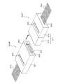
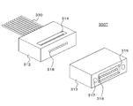
- FIG. 5 is a perspective view showing an example of a transmission side optical connector 300T and a reception side optical connector 300R that form an optical coupling connector.
- FIG. 6 is also a perspective view showing an example of the transmitting side optical connector 300T and the receiving side optical connector 300R, but is a view seen from the opposite direction to FIG.
- the illustrated example corresponds to parallel transmission of optical signals of a plurality of channels.
- the one corresponding to the parallel transmission of the optical signals of a plurality of channels is shown, the detailed description is omitted, but the one corresponding to the transmission of the optical signal of one channel can be similarly configured.
- the transmission side optical connector 300T includes a connector body 311 having a substantially rectangular parallelepiped appearance.
- the connector body 311 is configured by connecting a first optical section 312 and a second optical section 313.
- the connector body 311 is composed of the first and second optical parts 312 and 313 as described above, although not shown in FIGS. 5 and 6, the first lens can be easily manufactured. You can
- a plurality of optical fibers 330 respectively corresponding to the respective channels are connected to the back side of the first optical unit 312 in a state of being aligned in the horizontal direction.
- the tip end side of each optical fiber 330 is inserted and fixed in the optical fiber insertion hole 320.
- the optical fiber 330 constitutes a light emitter.
- an adhesive injection hole 314 having a rectangular opening is formed on the upper surface side of the first optical portion 312. From this adhesive injection hole 314, an adhesive for fixing the optical fiber 330 to the first optical portion 312 is inserted.
- a concave light emitting portion (light transmitting space) 315 having a rectangular opening is formed on the front surface side of the second optical portion 313, and the bottom portion of the light emitting portion 315 corresponds to each channel. Then, the plurality of second lenses (convex lenses) 316 are formed in a state of being aligned in the horizontal direction. This prevents the surface of the second lens 316 from accidentally hitting the mating connector or the like and being damaged.
- a position regulating portion 317 having a convex shape or a concave shape, which is a concave shape in the illustrated example, for alignment with the reception side optical connector 300R. ..
- the optical axis can be easily aligned when connecting to the receiving side optical connector 300R.
- 7 and 8 are perspective views showing a state in which the first optical section 312 and the second optical section 313 which form the connector main body 311 are separated. 7 and 8 are views seen from opposite directions.
- a plurality of first lenses (convex lenses) 318 are formed in a line in the horizontal direction corresponding to each channel.
- a concave space 319 having a rectangular opening is formed on the back side of the second optical unit 313.
- the first optical unit 312 and the second optical unit 313 are connected to form the connector body 311 (see FIGS. 5 and 6).
- the space 319 formed on the rear surface side of the second optical unit 313 is hermetically sealed on the front surface side of the first optical unit 312 to form a hermetically sealed space.
- the first lens 318 formed on the front surface side of the first optical unit 312 is in a state of being located in the closed space 319.
- the receiving side optical connector 300R includes a connector body 351 having a substantially rectangular parallelepiped appearance.
- a plurality of optical fibers 370 corresponding to the respective channels are connected.
- each optical fiber 370 has its tip end inserted and fixed in the optical fiber insertion hole 356.
- an adhesive injection hole 352 having a rectangular opening is formed on the upper surface side of the connector body 351. An adhesive for fixing the optical fiber 370 to the connector body 351 is inserted from the adhesive injection hole 352.
- a concave light incident portion (light transmission space) 353 having a rectangular opening is formed on the front surface side of the connector body 351, and a lens 354 corresponding to each channel is formed on the bottom portion of the light incident portion 353. Are located. This prevents the surface of the lens 354 from accidentally hitting the mating connector or the like and being damaged.
- a position regulating portion 355 having a concave shape or a convex shape, in the illustrated example, a convex shape for aligning with the transmission side optical connector 300T is integrally formed.
- the position restricting portion 355 is not limited to the one integrally formed with the connector body 351, and a pin may be used or another method may be used.
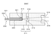
- FIG. 9 is a sectional view showing an example of the transmitting side optical connector 300T.
- the position restricting portion 317 (see FIG. 5) is omitted.
- the transmission side optical connector 300T will be further described with reference to FIG.
- the transmitting-side optical connector 300T includes a connector body 311 configured by connecting a first optical section 312 and a second optical section 313.
- the first optical portion 312 is made of a light-transmitting material such as synthetic resin or glass, or a material such as silicon that transmits a specific wavelength, and has a configuration of a ferrule with a lens.
- the first optical unit 312 By thus configuring the first optical unit 312 as a ferrule with a lens, the optical axes of the optical fiber 330 and the first lens 318 can be easily aligned. Further, since the first optical unit 312 is configured as a ferrule with a lens in this way, even in the case of multiple channels, multichannel communication can be easily realized by simply inserting the optical fiber 330 into the ferrule.
- the first optical unit 312 On the front surface side of the first optical unit 312, a plurality of first lenses 318 corresponding to the respective channels are integrally formed in a state of being aligned in the horizontal direction. As a result, the positional accuracy of the first lens 318 with respect to the core 331 of the optical fiber 330 installed in the first optical unit 312 can be simultaneously improved in a plurality of channels.
- the first optical unit 312 is provided with a plurality of optical fiber insertion holes 320 extending from the back side to the front side in a state of being aligned in the horizontal direction so as to be aligned with the first lens 318 of each channel.
- the optical fiber 330 has a double structure of a core 331 at the central portion that serves as an optical path and a clad 332 that covers the core.
- the optical fiber insertion hole 320 of each channel is formed so that the core 331 of the optical fiber 330 inserted therein and the optical axis of the corresponding first lens 318 coincide with each other. Further, the optical fiber insertion hole 320 of each channel is adjusted so that the bottom position thereof, that is, the contact position of the tip (emission end) when the optical fiber 330 is inserted matches the focal position of the first lens 318. , Molded.
- an adhesive injection hole 314 extending downward from the upper surface side is formed so as to communicate with the vicinity of the bottom position of the plurality of optical fiber insertion holes 320 arranged in the horizontal direction.
- the adhesive 321 is injected around the optical fiber 330 from the adhesive injection hole 314, so that the optical fiber 330 is fixed to the first optical portion 312.
- the adhesive 321 is a light transmissive agent and is injected between the tip of the optical fiber 330 and the bottom position of the optical fiber insertion hole 320, whereby reflection can be reduced.
- the second optical unit 313 is made of, for example, a light transmissive material such as synthetic resin or glass, or a material such as silicon that transmits a specific wavelength.
- the second optical section 313 is connected to the first optical section 312 to form the connector body 311. If the coefficients of thermal expansion are made uniform, the optical path shift due to the strain in the two optical parts when the heat changes can be suppressed, so that the material of the second optical part 313 is the same as the material of the first optical part 312. It is preferable that there is one, but another material may be used.
- a concave light emitting portion (light transmission space) 315 is formed on the front surface side of the second optical portion 313. Then, a plurality of second lenses 316 corresponding to the respective channels are integrally formed in the second optical unit 313 so as to be located at the bottom portion of the light emitting unit 315 in a state where they are aligned in the horizontal direction. Has been done. Thereby, the positional accuracy of the second lens 316 with respect to the second optical unit 313 can be improved.
- a concave space 319 is formed on the back side of the second optical unit 313.
- This space 319 is hermetically sealed on the front side of the first optical unit 312 to form a hermetically sealed space.
- the first lens 318 of each channel formed on the front surface side of the first optical unit 312 is in a state of being located in this closed space 319.
- the connector body 311 is configured by connecting the first optical section 312 and the second optical section 313.
- this connection method a method in which a concave portion is newly provided on one side and a convex portion is newly provided on the other side such as a boss, and fitting is performed, or a method of aligning the optical axis positions of the lenses with an image processing system or the like and adhering and fixing the lenses is adopted. obtain.
- the first lens 318 has a function of converging the light emitted from the optical fiber 330 which is a light emitting body.
- the second lens 316 has a function of shaping the light converged by the first lens 318 into collimated light and emitting the light.
- the light emitted from the emission end of the optical fiber 330 with a predetermined NA is incident on the first lens 318 and converged (angle is narrowed), and the converged light is incident on the second lens 316.
- the collimated light is shaped and emitted.
- FIG. 10 is a sectional view showing an example of the receiving side optical connector 300R.
- the position restricting portion 355 (see FIGS. 5 and 6) is omitted.
- the receiving side optical connector 300R will be further described with reference to FIG.
- the receiving side optical connector 300R includes a connector body 351.
- the connector body 351 is made of, for example, a light-transmitting material such as synthetic resin or glass, or a material such as silicon that transmits a specific wavelength, and has a configuration of a ferrule with a lens.
- a concave light incident portion (light transmission space) 353 is formed on the front surface side of the connector body 351.
- a plurality of lenses (convex lenses) 354 corresponding to the respective channels are integrally formed in the connector main body 351 so as to be located at the bottom of the light incident portion 353 in a state of being aligned in the horizontal direction. ..
- the connector main body 351 is provided with a plurality of optical fiber insertion holes 356 extending from the back side to the front side in line with the lens 354 of each channel in a horizontal direction.
- the optical fiber 370 has a double structure of a core 371 in the central portion that serves as an optical path and a clad 372 that covers the periphery thereof.
- the optical fiber insertion hole 356 of each channel is formed so that the optical axis of the lens 354 corresponding to the core 371 of the optical fiber 370 inserted therein matches. Further, the optical fiber insertion hole 356 of each channel is formed so that its bottom position, that is, the contact position of its tip (incident end) when the optical fiber 370 is inserted matches the focal position of the lens 354. ing.
- an adhesive injection hole 352 extending downward from the upper surface side is formed in the connector body 351 so as to communicate with the vicinity of the bottom positions of the plurality of optical fiber insertion holes 356 which are aligned in the horizontal direction. .. After the optical fiber 370 is inserted into the optical fiber insertion hole 356, the adhesive 357 is injected around the optical fiber 370 from the adhesive injection hole 352, so that the optical fiber 370 is fixed to the connector body 351.
- the lens 354 has a function of condensing the incident collimated light.
- the collimated light is incident on the lens 354 and is condensed, and the condensed light is incident on the incident end of the optical fiber 370 which is the light receiving body with a predetermined NA.
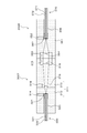
- FIG. 11 shows a cross-sectional view of a transmission side optical connector 300T and a reception side optical connector 300R that form an optical coupling connector.
- the illustrated example shows a state in which the transmission side optical connector 300T and the reception side optical connector 300R are connected.
- the light transmitted through the optical fiber 330 is emitted from the emission end of the optical fiber 330 with a predetermined NA.
- the emitted light enters the first lens 318 and is converged.
- the converged light is incident on the second lens 316, is shaped into collimated light, and is emitted toward the reception side optical connector 300R.
- the light emitted from the transmitting side optical connector 300T is incident on the lens 354 and is condensed. Then, the condensed light is incident on the incident end of the optical fiber 370 and is sent through the optical fiber 370.
- the transmission side optical connector 300T converges the light emitted from the optical fiber 330 as the light emitting body by the first lens 318, and collects the converged light into the second light.
- the light is shaped into collimated light by the lens 316 and emitted. Therefore, it is possible to prevent the distance from the optical fiber 330 from the second lens 316 from becoming long and to control the diameter of the light from the optical fiber 330 so as to be within the diameter of the second lens 316.
- By increasing the focal length of the lens 316 it is possible to reduce the coupling loss of the optical power on the receiving side with respect to the axis shift on the transmitting side.
- the angle of the light incident on the second lens 316 becomes gentle, and the curvature of the second lens 316 also becomes gentle so that the transmitting side has a small curvature.
- the deviation of the light-collecting point on the receiving side with respect to the axis deviation of is suppressed.
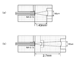
- the mode field diameter (MFD) of the optical fiber is 8 ⁇ m, and an optical system having an NA of the optical fiber of 0.15 and a collimator aperture of 180 ⁇ m is used.
- FIG. 12A shows an example of the configuration of a normal transmission side optical connector.
- FIG.12(b) has shown the structural example of the transmission side optical connector by this technique.
- the structure of the receiving side optical connector is the same as the structure of the conventional transmitting side optical connector shown in FIG.
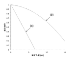
- the graph in FIG. 13 shows a simulation result of the coupling efficiency of light input to the optical fiber on the receiving side.
- the horizontal axis represents the axis shift amount, which indicates the shift amount when the light source shifts in the direction perpendicular to the optical axis, and the vertical axis indicates the light coupling efficiency on the receiving side.
- the solid line (a) shows the relationship between the amount of axis deviation and the coupling efficiency when the normal transmission-side optical connector shown in FIG. 12(a) is used.
- the solid line (b) shows the relationship between the amount of axial deviation and the coupling efficiency when the transmission side optical connector according to the present technology shown in FIG. 12(b) is used.
- the MFD of the optical fiber is 8 ⁇ m, for example, when the amount of axis deviation is 5 ⁇ m, when the normal optical connector on the transmission side shown in FIG. Power loss occurs.
- the transmission side optical connector according to the present technology shown in FIG. 12B is used, the power loss is about 10% from the solid line (b), and the power loss is significantly reduced.
- FIG. 14 is a cross-sectional view showing a transmitting side optical connector 300T-1 as another configuration example 1. 14, parts corresponding to those in FIG. 9 are designated by the same reference numerals, and detailed description thereof will be appropriately omitted.
- the first lens 318 is formed not on the front side of the first optical section 312 but on the bottom part of the space 319 formed on the back side of the second optical section 313. It
- the space 319 formed on the back side of the second optical section 313 is on the front side of the first optical section 312. It becomes a closed space by being sealed. Therefore, also in this transmission side optical connector 300T-1, as in the transmission side optical connector 300T of FIG. 9, the first lens 318 is placed in the closed space 319, and dust, dust, etc. on the surface thereof. Can be prevented in advance.
- FIG. 15 is a sectional view showing a transmitting side optical connector 300T-2 as another configuration example 2. 15, parts corresponding to those in FIG. 9 are designated by the same reference numerals, and detailed description thereof will be appropriately omitted.
- a second first lens (convex lens) 322 is formed in the bottom portion of the space 319 formed on the back side of the second optical unit 313.
- the light emitted from the emission end of the optical fiber 330 with a predetermined NA is incident on the first lens 318 and is converged (angle is narrowed), and the converged light is Is incident on the second first lens 322 and further converged (angle is narrowed), and the converged light is incident on the second lens 316, shaped into collimated light, and emitted.
- the spherical height of each of the two first lenses 318 and 322 can be lowered, It is possible to improve the ease of molding the lens.
- the two first lenses 318 and 322 are in a state of being located in the closed space 319 and dust on the surface thereof. It is possible to prevent dust from adhering.
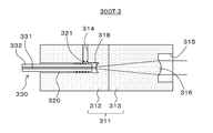
- FIG. 16 is a sectional view showing a transmitting side optical connector 300T-3 as another configuration example 3. 16, parts corresponding to those in FIG. 9 are designated by the same reference numerals, and detailed description thereof will be appropriately omitted.
- the first lens 318 is formed not at the front surface side of the first optical portion 312 but at the deepest bottom portion of the optical fiber insertion hole 320. By thus forming the first lens 318 in the bottom portion of the optical fiber insertion hole 320, it is possible to further improve the accuracy of optical axis alignment between the optical fiber 330 and the first lens 318.
- the tip of the optical fiber 330 is not abutted against the bottom portion of the fiber insertion hole 320, and a constant distance is maintained from this bottom portion, that is, the first lens 318. It is necessary to fix it at the focal position of.
- the optical fiber 330 when the optical fiber 330 is bonded and fixed to the first optical portion 312, if the adhesive 321 enters between the tip of the optical fiber 330 and the first lens 318, the optical characteristics change.
- the formation position of the adhesive injection hole 314 for injecting the adhesive 321 is to avoid the tip of the optical fiber 330 so that the adhesive 321 does not enter between the tip of the optical fiber 330 and the first lens 318. Need to
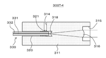
- FIG. 17 is a sectional view showing a transmitting side optical connector 300T-4 as another configuration example 4. 17, parts corresponding to those in FIGS. 9 and 16 are designated by the same reference numerals, and detailed description thereof will be appropriately omitted.
- the connector main body 311 is composed of one optical section. This is possible because forming the first lens 318 at the bottom of the optical fiber insertion hole 320 eliminates the need to create a space 319 in the optical section.
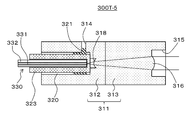
- FIG. 18 is a sectional view showing a transmitting side optical connector 300T-5 as another configuration example 5. 18, parts corresponding to those in FIGS. 9 and 16 are designated by the same reference numerals, and detailed description thereof will be appropriately omitted.
- the transmission side optical connector 300T-5 the diameter of the optical fiber insertion hole 320 formed in the first optical section 312 is increased. Then, the ferrule 323 to which the optical fiber 330 is fixed by abutting in advance is inserted into the optical fiber insertion hole 320, and is fixed by the adhesive 321. With such a configuration, it becomes easy to keep the tip of the optical fiber 330 at a constant distance from the first lens 318.
- FIG. 19 is a sectional view showing a transmitting side optical connector 300T-6 as another configuration example 6. 19, parts corresponding to those in FIGS. 9, 16 and 18 are designated by the same reference numerals, and detailed description thereof will be appropriately omitted.
- the connector main body 311 is composed of one optical section. Others are configured similarly to the transmission side optical connector 300T-5 in FIG.
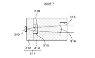
- FIG. 20 is a cross-sectional view showing a transmitting side optical connector 300T-7 as another configuration example 7. 20, parts corresponding to those in FIG. 9 are designated by the same reference numerals, and detailed description thereof will be appropriately omitted.
- the transmitting side optical connector 300T-7 the light emitting body fixed to the first optical unit 312 is not the optical fiber 330 but a light emitting element 340 such as VCSEL (Vertical Cavity Surface Emitting LASER). Is.
- VCSEL Vertical Cavity Surface Emitting LASER
- a plurality of light emitting elements 340 are fixed on the back surface side of the first optical unit 312, aligned in the horizontal direction, in alignment with the first lens 318 of each channel. Then, in this case, the light emitting element 340 of each channel is fixed such that the emitting portion thereof coincides with the optical axis of the corresponding first lens 318. Further, in this case, the thickness and the like of the first optical unit 312 in the optical axis direction are set such that the emitting portions of the light emitting elements 340 of the respective channels match the focal positions of the corresponding first lenses 318. ..
- the light emitted from the emitting portion of the light emitting element 340 with a predetermined NA is incident on the first lens 318 and is converged (angle is narrowed), and the converged light is Is incident on the second lens 316, shaped into collimated light, and emitted.
- FIG. 21 is a sectional view showing a transmitting side optical connector 300T-8 as another configuration example 8. 21, parts corresponding to those in FIGS. 9 and 20 are designated by the same reference numerals, and detailed description thereof will be omitted as appropriate.
- the substrate 341 on which the light emitting element 340 is mounted is fixed to the lower surface side of the connector body 311. In this case, a plurality of light emitting elements 340 are mounted on the substrate 341 so as to be aligned in the horizontal direction so as to match the first lens 318 of each channel.
- the first optical portion 312 has a light emitting element placement hole 324 extending upward from the lower surface side. Then, in order to change the optical path of the light from the light emitting element 340 of each channel to the direction of the corresponding first lens 318, the bottom portion of the light emitting element placement hole 324 is an inclined surface, and the mirror 342 is formed on this inclined surface. Are arranged. As for the mirror 342, it is conceivable that not only the separately generated mirror 342 is fixed to the inclined surface, but also the inclined surface is formed by vapor deposition or the like.
- the position of the substrate 341 is adjusted and fixed so that the emission parts of the light emitting elements 340 of the respective channels are aligned with the optical axes of the corresponding first lenses 318. Further, in this case, the formation position of the first lens 318 and the formation position of the light emitting element disposition hole 324 are adjusted so that the emission parts of the light emitting elements 340 of the respective channels match the focal positions of the corresponding first lenses 318. -The length etc. are set.
- the light emitted from the emitting portion of the light emitting element 340 with a predetermined NA is changed in its optical path by the mirror 342 and then is incident on the first lens 318 and converged (the angle is narrowed). This converged light is incident on the second lens 316, shaped into collimated light, and emitted.
- the substrate 341 on which the light emitting element 340 is mounted is fixed to the connector body 311, an optical fiber is not required when transmitting an optical signal from the light emitting element 340, and the cost can be reduced. .. Further, since the light from the light emitting element 340 placed on the substrate 341 is changed in the optical path by the mirror 342 and incident on the first lens 318, the mounting is facilitated and the degree of design freedom is increased. it can.
- FIG. 22 is a sectional view showing a transmitting side optical connector 300T-9 as another configuration example 9. 22, parts corresponding to those in FIGS. 9 and 21 are designated by the same reference numerals, and detailed description thereof will be omitted as appropriate.
- the first optical portion 312 has optical fiber insertion holes 325 extending upward from the lower surface side aligned with the first lens 318 of each channel in the horizontal direction. Are formed in multiple.
- each optical fiber insertion hole 325 In order to change the optical path of the light from the optical fiber 330 inserted into each optical fiber insertion hole 325 toward the corresponding first lens 318, the bottom portion of each optical fiber insertion hole 325 is an inclined surface. A mirror 342 is arranged on the inclined surface. Further, each optical fiber insertion hole 325 is formed so that the core 331 of the optical fiber 330 inserted therein and the optical axis of the corresponding first lens 318 coincide with each other.
- the optical fiber 330 of the corresponding channel is inserted into each optical fiber insertion hole 325, and is fixed by, for example, injecting an adhesive agent (not shown) around the optical fiber 330.
- the optical fiber 330 has its tip (emission end) aligned with the focal position of the corresponding first lens 318, and therefore has its tip (emission end) located at a constant distance from the mirror 342. , Its insertion position is set.
- the light emitted from the emission end of the optical fiber 330 with a predetermined NA is changed in the optical path by the mirror 342 and then is incident on the first lens 318 and converged (the angle is narrowed). This converged light is incident on the second lens 316, shaped into collimated light, and emitted.
- the first optical unit 312 since the first optical unit 312 has the configuration of a ferrule with a lens, the optical axes of the optical fiber 330 and the first lens 318 can be easily adjusted. Further, in the case of this configuration example, since the optical path of the light from the optical fiber 330 is changed by the mirror 342, mounting is facilitated and the degree of freedom in design can be increased.
- FIG. 23 is a cross-sectional view showing a transmitting side optical connector 300T-10 as another configuration example 10. 23, parts corresponding to those in FIGS. 9, 18 and 22 are denoted by the same reference numerals, and detailed description thereof will be appropriately omitted.
- the transmission side optical connector 300T-10 the diameter of the optical fiber insertion hole 325 formed in the first optical portion 312 is increased. Then, the ferrule 323 to which the optical fiber 330 is fixed by abutting in advance is inserted into the optical fiber insertion hole 325, and is fixed by, for example, an adhesive (not shown). With such a configuration, it becomes easy to keep the tip position of the optical fiber 330 at a constant distance from the mirror 342.
- FIG. 24 shows an optical coupling connector that uses convergent light (light bent in the light collecting direction) instead of collimated light. 24, parts corresponding to those in FIG. 3 are designated by the same reference numerals.
- An optical connector including a connector body having a first lens that converges light emitted from a light-emitting body and a second lens that shapes and emits light converged by the first lens.
- the connector body has a closed space, The optical connector according to (1), wherein the first lens is located in the closed space.
- the connector body comprises a first optical section on which the light emitted from the light emitting body is incident and a second optical section having the second lens, and the connector body according to (1) to (3) above.
- the optical connector according to any one.
- the light emitter is an optical fiber
- the optical connector according to (7), wherein the insertion hole is an insertion hole for inserting a ferrule in which the optical fiber is inserted and fixed.
- the connector body has an optical path changing portion for changing an optical path at a bottom portion of the insertion hole, and the light emitted from the optical fiber is changed in the optical path changing portion so that the first lens is provided.
- the optical connector according to any one of (6) to (8), which is incident on the optical connector.
- the optical connector according to any one of (1) to (5), wherein the light emitter is a light emitting element that converts an electric signal into an optical signal.
- the light emitting element is connected to the connector body, The optical connector according to (10), wherein the light emitted from the light emitting element is incident on the first lens without changing the optical path.
- the connector body has an optical path changing portion for changing the optical path, The light emitting element is fixed to the substrate, The optical connector according to (10), wherein the light emitted from the light emitting element has its optical path changed by the optical path changing unit and is incident on the first lens.
- the connector body is Made of light transmissive material, The optical connector according to any one of (1) to (13), which integrally has the first lens and the second lens.
- the connector body has a concave light emitting portion
- the said 2nd lens is an optical connector in any one of said (1) to (15) located in the bottom part of the said light emission part.
- the connector body has integrally a convex or concave position regulating portion on the front side for aligning with the connector of the connection partner side.
- the optical connector described.
- the optical connector is An optical cable comprising a connector body having a first lens that converges light emitted from a light-emitting body and a second lens that shapes and emits light converged by the first lens.
- An electronic device having an optical connector as a receptacle The optical connector is An electronic device comprising: a connector body having a first lens that converges light emitted from a light-emitting body and a second lens that shapes and emits light converged by the first lens.
- Optical communication unit 102... Light emitting unit 103, 104... Optical transmission line 105... Light receiving unit 200A, 200B... Optical cable 201A, 201B... Cable body 300T , 300T-1 to 300T-10... Transmitting side optical connector 300R... Receiving side optical connector 311... Connector body 312... First optical section 313... Second optical section 314... Adhesive injection hole 315... Light emitting part 316... Second lens 317... Position regulating part 318... First lens 319... Space (closed space) 320... Optical fiber insertion hole 321... Adhesive 322... First lens 323... Ferrule 324... Light emitting element placement hole 325... Optical fiber insertion hole 330...
- Optical fiber 331 ... Core 340... Light emitting element 341... Substrate 342... Mirror... 332... Clad 351... Connector body 352; Adhesive insertion hole 353... Light incident part 354... -Lens 355... Position control part 356... Optical fiber insertion hole 357... Adhesive 370... Optical fiber 371... Core 372... Clad
Landscapes
- Physics & Mathematics (AREA)
- General Physics & Mathematics (AREA)
- Optics & Photonics (AREA)
- Optical Couplings Of Light Guides (AREA)
- Mechanical Coupling Of Light Guides (AREA)
Abstract
Ce connecteur optique atténue favorablement la perte de couplage de puissance optique côté réception due au désalignement axial côté transmission. Le connecteur optique est pourvu d'un corps de connecteur qui maintient une première lentille et une seconde lentille. La première lentille converge la lumière émise par un corps luminescent. La seconde lentille forme et émet la lumière convergée par la première lentille. La deuxième lentille forme la lumière émise par la première lentille en lumière collimatée, par exemple. Tout en supprimant des augmentations de la distance du corps électroluminescent à la seconde lentille et en limitant le diamètre de la lumière provenant du corps électroluminescent à l'intérieur du second diamètre de lentille, il est possible d'allonger la distance focale de la seconde lentille et d'atténuer la perte de couplage de puissance optique côté réception due à un désalignement axial sur le côté transmission.
Priority Applications (3)
| Application Number | Priority Date | Filing Date | Title |
|---|---|---|---|
| CN201980080347.2A CN113167975B (zh) | 2018-12-13 | 2019-11-21 | 光连接器、光缆以及电子装置 |
| US17/309,523 US20220026648A1 (en) | 2018-12-13 | 2019-11-21 | Optical connector, optical cable, and electronic device |
| JP2020559905A JP7384172B2 (ja) | 2018-12-13 | 2019-11-21 | 光結合コネクタ |
Applications Claiming Priority (2)
| Application Number | Priority Date | Filing Date | Title |
|---|---|---|---|
| JP2018-233192 | 2018-12-13 | ||
| JP2018233192 | 2018-12-13 |
Publications (1)
| Publication Number | Publication Date |
|---|---|
| WO2020121769A1 true WO2020121769A1 (fr) | 2020-06-18 |
Family
ID=71076392
Family Applications (1)
| Application Number | Title | Priority Date | Filing Date |
|---|---|---|---|
| PCT/JP2019/045586 Ceased WO2020121769A1 (fr) | 2018-12-13 | 2019-11-21 | Connecteur optique, câble optique et dispositif électronique |
Country Status (4)
| Country | Link |
|---|---|
| US (1) | US20220026648A1 (fr) |
| JP (1) | JP7384172B2 (fr) |
| CN (1) | CN113167975B (fr) |
| WO (1) | WO2020121769A1 (fr) |
Cited By (1)
| Publication number | Priority date | Publication date | Assignee | Title |
|---|---|---|---|---|
| JPWO2021230294A1 (fr) * | 2020-05-14 | 2021-11-18 |
Families Citing this family (1)
| Publication number | Priority date | Publication date | Assignee | Title |
|---|---|---|---|---|
| CN119916536A (zh) * | 2025-04-03 | 2025-05-02 | 苏州旭创科技有限公司 | 连接器组件及连接器组件的制造方法 |
Citations (9)
| Publication number | Priority date | Publication date | Assignee | Title |
|---|---|---|---|---|
| JPS641888B2 (fr) * | 1981-02-25 | 1989-01-13 | Fujitsu Ltd | |
| JP2003098317A (ja) * | 2001-09-21 | 2003-04-03 | Ricoh Co Ltd | マイクロレンズ及び光結合装置 |
| JP2012003245A (ja) * | 2010-05-17 | 2012-01-05 | Sumitomo Electric Ind Ltd | 光コネクタモジュール |
| JP2012032727A (ja) * | 2010-08-03 | 2012-02-16 | Yazaki Corp | 小径曲げ光コネクタ |
| JP2014145987A (ja) * | 2013-01-30 | 2014-08-14 | Auto Network Gijutsu Kenkyusho:Kk | 光コネクタおよび光コネクタ装置 |
| JP2015018039A (ja) * | 2013-07-09 | 2015-01-29 | 株式会社オートネットワーク技術研究所 | 光モジュール |
| JP2015031818A (ja) * | 2013-08-02 | 2015-02-16 | 住友電気工業株式会社 | レンズ部品、光モジュール |
| CN104570234A (zh) * | 2013-10-29 | 2015-04-29 | 鸿富锦精密工业(深圳)有限公司 | 光耦合透镜 |
| JP2017049613A (ja) * | 2016-11-30 | 2017-03-09 | 株式会社エンプラス | レンズアレイおよびこれを備えた光モジュール |
Family Cites Families (5)
| Publication number | Priority date | Publication date | Assignee | Title |
|---|---|---|---|---|
| JP2007133079A (ja) * | 2005-11-09 | 2007-05-31 | Hitachi Cable Ltd | 光モジュール |
| JP2008225339A (ja) * | 2007-03-15 | 2008-09-25 | Hitachi Cable Ltd | 光学系接続構造、光学部材及び光伝送モジュール |
| WO2017002149A1 (fr) * | 2015-07-02 | 2017-01-05 | オリンパス株式会社 | Système de transmission de signal optique et réceptacle optique |
| CN107436465A (zh) * | 2016-05-28 | 2017-12-05 | 鸿富锦精密工业(深圳)有限公司 | 光传输模组及应用该光传输模组的光传输装置 |
| EP4350405A3 (fr) | 2017-06-16 | 2024-10-09 | Kyocera Corporation | Module de connecteur optique |
-
2019
- 2019-11-21 US US17/309,523 patent/US20220026648A1/en not_active Abandoned
- 2019-11-21 JP JP2020559905A patent/JP7384172B2/ja active Active
- 2019-11-21 CN CN201980080347.2A patent/CN113167975B/zh active Active
- 2019-11-21 WO PCT/JP2019/045586 patent/WO2020121769A1/fr not_active Ceased
Patent Citations (9)
| Publication number | Priority date | Publication date | Assignee | Title |
|---|---|---|---|---|
| JPS641888B2 (fr) * | 1981-02-25 | 1989-01-13 | Fujitsu Ltd | |
| JP2003098317A (ja) * | 2001-09-21 | 2003-04-03 | Ricoh Co Ltd | マイクロレンズ及び光結合装置 |
| JP2012003245A (ja) * | 2010-05-17 | 2012-01-05 | Sumitomo Electric Ind Ltd | 光コネクタモジュール |
| JP2012032727A (ja) * | 2010-08-03 | 2012-02-16 | Yazaki Corp | 小径曲げ光コネクタ |
| JP2014145987A (ja) * | 2013-01-30 | 2014-08-14 | Auto Network Gijutsu Kenkyusho:Kk | 光コネクタおよび光コネクタ装置 |
| JP2015018039A (ja) * | 2013-07-09 | 2015-01-29 | 株式会社オートネットワーク技術研究所 | 光モジュール |
| JP2015031818A (ja) * | 2013-08-02 | 2015-02-16 | 住友電気工業株式会社 | レンズ部品、光モジュール |
| CN104570234A (zh) * | 2013-10-29 | 2015-04-29 | 鸿富锦精密工业(深圳)有限公司 | 光耦合透镜 |
| JP2017049613A (ja) * | 2016-11-30 | 2017-03-09 | 株式会社エンプラス | レンズアレイおよびこれを備えた光モジュール |
Cited By (2)
| Publication number | Priority date | Publication date | Assignee | Title |
|---|---|---|---|---|
| JPWO2021230294A1 (fr) * | 2020-05-14 | 2021-11-18 | ||
| JP7820293B2 (ja) | 2020-05-14 | 2026-02-25 | ヌヴォトンテクノロジージャパン株式会社 | 光源モジュール |
Also Published As
| Publication number | Publication date |
|---|---|
| CN113167975B (zh) | 2024-04-09 |
| JPWO2020121769A1 (ja) | 2021-10-21 |
| JP7384172B2 (ja) | 2023-11-21 |
| US20220026648A1 (en) | 2022-01-27 |
| CN113167975A (zh) | 2021-07-23 |
Similar Documents
| Publication | Publication Date | Title |
|---|---|---|
| JP2020060796A (ja) | 光コネクタ及び光コネクタシステム並びにこれらを備えたアクティブ光ケーブル | |
| CN113316731B (zh) | 光通信装置、光通信方法和光通信系统 | |
| US9733438B2 (en) | Optical connector for data transceiver modules and lens block for optical connectors | |
| WO2020184094A1 (fr) | Dispositif de communication optique, procédé de communication optique et système de communication optique | |
| JP6532236B2 (ja) | 光レセプタクルおよび光モジュール | |
| US9500820B2 (en) | Fiber assembly | |
| US12013582B2 (en) | Optical communication apparatus, optical communication method, and optical communication system | |
| US11474300B2 (en) | Optical communication connector, optical transmitter, optical receiver, optical communication system, and optical communication cable | |
| JP7384172B2 (ja) | 光結合コネクタ | |
| US20180095230A1 (en) | Optical module | |
| JP7428140B2 (ja) | 光コネクタ、光ケーブルおよび電子機器 | |
| WO2020153239A1 (fr) | Connecteur optique, câble optique et appareil électronique | |
| WO2020153238A1 (fr) | Connecteur optique, câble optique et appareil électronique | |
| US9063311B2 (en) | Optical fiber connector and optical fiber coupling assembly having same | |
| US20120288237A1 (en) | Optical fiber module | |
| JP7459519B2 (ja) | 光通信装置、光通信方法および光通信システム | |
| WO2020209075A1 (fr) | Connecteur optique, câble optique et dispositif électronique | |
| JP2014010186A (ja) | 光コネクタ | |
| JP2009251298A (ja) | 光コネクタモジュール | |
| JP2008026811A (ja) | 光結合装置 |
Legal Events
| Date | Code | Title | Description |
|---|---|---|---|
| 121 | Ep: the epo has been informed by wipo that ep was designated in this application |
Ref document number: 19896803 Country of ref document: EP Kind code of ref document: A1 |
|
| ENP | Entry into the national phase |
Ref document number: 2020559905 Country of ref document: JP Kind code of ref document: A |
|
| NENP | Non-entry into the national phase |
Ref country code: DE |
|
| 122 | Ep: pct application non-entry in european phase |
Ref document number: 19896803 Country of ref document: EP Kind code of ref document: A1 |