WO2020184094A1 - Dispositif de communication optique, procédé de communication optique et système de communication optique - Google Patents
Dispositif de communication optique, procédé de communication optique et système de communication optique Download PDFInfo
- Publication number
- WO2020184094A1 WO2020184094A1 PCT/JP2020/006380 JP2020006380W WO2020184094A1 WO 2020184094 A1 WO2020184094 A1 WO 2020184094A1 JP 2020006380 W JP2020006380 W JP 2020006380W WO 2020184094 A1 WO2020184094 A1 WO 2020184094A1
- Authority
- WO
- WIPO (PCT)
- Prior art keywords
- optical
- wavelength
- light
- optical path
- core
- Prior art date
- Legal status (The legal status is an assumption and is not a legal conclusion. Google has not performed a legal analysis and makes no representation as to the accuracy of the status listed.)
- Ceased
Links
Images


Classifications
-
- H—ELECTRICITY
- H04—ELECTRIC COMMUNICATION TECHNIQUE
- H04B—TRANSMISSION
- H04B10/00—Transmission systems employing electromagnetic waves other than radio-waves, e.g. infrared, visible or ultraviolet light, or employing corpuscular radiation, e.g. quantum communication
- H04B10/25—Arrangements specific to fibre transmission
- H04B10/2581—Multimode transmission
-
- G—PHYSICS
- G02—OPTICS
- G02B—OPTICAL ELEMENTS, SYSTEMS OR APPARATUS
- G02B6/00—Light guides; Structural details of arrangements comprising light guides and other optical elements, e.g. couplings
- G02B6/24—Coupling light guides
- G02B6/26—Optical coupling means
- G02B6/32—Optical coupling means having lens focusing means positioned between opposed fibre ends
-
- G—PHYSICS
- G02—OPTICS
- G02B—OPTICAL ELEMENTS, SYSTEMS OR APPARATUS
- G02B6/00—Light guides; Structural details of arrangements comprising light guides and other optical elements, e.g. couplings
- G02B6/24—Coupling light guides
- G02B6/26—Optical coupling means
- G02B6/268—Optical coupling means for modal dispersion control, e.g. concatenation of light guides having different modal dispersion properties
-
- H—ELECTRICITY
- H04—ELECTRIC COMMUNICATION TECHNIQUE
- H04B—TRANSMISSION
- H04B10/00—Transmission systems employing electromagnetic waves other than radio-waves, e.g. infrared, visible or ultraviolet light, or employing corpuscular radiation, e.g. quantum communication
- H04B10/40—Transceivers
Definitions
- This technology relates to optical communication devices, optical communication methods, and optical communication systems. More specifically, the present invention relates to an optical communication device or the like capable of alleviating the accuracy of misalignment.
- the purpose of this technology is to reduce the accuracy of misalignment and reduce costs.
- the concept of this technology is
- the first wavelength has an optical waveguide that propagates only in basic mode. Communicate using light having a second wavelength and at least a primary mode component together with the basic mode.
- the second wavelength is in an optical communication device, which is a wavelength at which the optical waveguide can propagate at least the primary mode together with the basic mode.
- an optical waveguide that propagates only the basic mode at the first wavelength.
- the optical waveguide may be an optical fiber or a silicon optical waveguide.
- the first wavelength may be a wavelength at which the wavelength dispersion becomes zero.
- the first wavelength may be set to be between 300 nm and 5 ⁇ m.
- the first wavelength may be a wavelength in the 1310 nm band or the 1550 nm band.
- the second wavelength is a wavelength at which the optical waveguide can propagate at least the primary mode together with the basic mode.
- the second wavelength is shorter than the first wavelength.
- the second wavelength may be a wavelength in the 850 nm band.
- an optical waveguide that propagates only the basic mode at the first wavelength is provided, and the optical waveguide has a second wavelength that can propagate at least the primary mode together with the basic mode. Communication is performed using light having at least a primary mode component together with the basic mode.
- communication is performed using light of the second wavelength, and at least the component of the primary mode generated by the optical axis shift propagates along the optical waveguide together with the component of the basic mode, so that the light due to the optical axis shift is transmitted. It is possible to reduce the power coupling loss. Further, in this case, communication is performed using light having at least a primary mode component together with the basic mode, and the optical axis shift of the light incident on the optical waveguide depends on the direction of the shift. Although two wavelengths are used, it is possible to increase the coupling efficiency of optical power as compared with the case where communication is performed using light composed of components of the basic mode.
- an optical path adjusting unit that adjusts the optical path so as to guide the input light to the core of the optical waveguide may be further provided.
- the optical path adjusting unit may adjust the optical path by utilizing the refraction by the lens.
- the optical path adjusting unit may adjust the optical path by utilizing the reflection by the optical path adjusting member having a tapered surface whose aperture gradually narrows toward the incident side of the optical waveguide. Good.
- the optical path adjusting portion is provided between the core and the clad at the incident end of the optical waveguide, and the surface in contact with the clad gradually expands from the same diameter as the core and gradually expands from the core to the clad.
- the optical path may be adjusted by using an optical path adjusting member whose refractive index gradually changes from the same refractive index as that of the core to the same refractive index as that of the clad.
- the optical path adjusting portion is provided on the incident side of the optical waveguide, has a refractive index equivalent to that of the core of the optical waveguide on the optical axis, and the refractive index decreases as the distance from the optical axis increases in the vertical direction.
- the optical path may be adjusted by using an optical path adjusting member having a refractive index of the structure.
- a receiver with an optical waveguide that propagates only the basic mode at the first wavelength The optical waveguide of the receiving unit is provided with a transmitting unit that injects light having a second wavelength and having at least a primary mode component together with the basic mode.
- the second wavelength is in an optical communication system, which is a wavelength at which the optical waveguide can propagate at least the primary mode together with the basic mode.
- This technology includes a receiving unit and a transmitting unit.
- the receiver has an optical waveguide that propagates only the basic mode at the first wavelength.
- Light having a second wavelength and having at least a primary mode component as well as a basic mode is incident on the optical waveguide of the receiving unit from the transmitting unit.
- the second wavelength is a wavelength at which the optical waveguide can propagate at least the primary mode together with the basic mode.
- the transmitter may be a receptacle of the transmitter, or a plug of a cable.
- the receiving unit has an optical waveguide that propagates only the basic mode at the first wavelength, and the optical waveguide is transmitted from the transmitting unit to the optical waveguide in at least the primary mode together with the basic mode.
- Light having a second wavelength capable of propagating the light and having a component of at least the primary mode together with the basic mode is incident. Therefore, it is possible to reduce the coupling loss of optical power due to the deviation of the optical axis.
- FIG. 1 shows an outline of optical communication by spatial coupling.
- the light emitted from the optical fiber 10T on the transmitting side is formed into collimated light by the lens 11T and emitted.
- this collimated light is condensed by the lens 11R on the receiving side and incident on the optical fiber 10R.
- the optical fibers 10T and 10R have a double structure consisting of a core 10a at the center of the optical path and a clad 10b covering the periphery thereof.
- FIG. 2A shows the basic structure of an optical fiber.
- An optical fiber has a structure in which a central portion called a core is covered with a layer called a clad.
- the refractive index n1 of the core is high
- the refractive index n2 of the cladding is low
- the light is confined in the core and propagates.
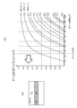
- FIG. 2B shows the LPml (Linearly Polarized) mode of the step-type optical fiber, in which the normalized propagation constant b is shown as a function of the normalized frequency V.
- the horizontal axis is the normalized frequency V, which can be expressed by the following mathematical formula (1).
- d is the core diameter
- NA is the numerical aperture
- ⁇ is the wavelength of light.
- V ⁇ dNA / ⁇ ⁇ ⁇ ⁇ (1)
- LP01 is a basic mode (0th-order mode), and thereafter LP11, LP21, ... Are the primary mode, the secondary mode, ..., Respectively.
- V 1.92.
- FIGS. 4 and 5 show an example of factors that deteriorate the accuracy of optical axis alignment.
- the optical axis shift occurs due to the non-uniform amount of the fixing materials 16T and 16R for fixing the ferrules 15T and 15R and the optical fibers 10T and 10R.
- the optical axis shift occurs due to insufficient shaping accuracy of the lenses 11T and 11R.
- the optical axis shift occurs due to insufficient accuracy of the positioning mechanism (recessed portion 17T, convex portion 17R) provided in the ferrules 15T and 15R.
- the convex portion 17R shown in FIGS. 5A and 5B may be a pin.
- an optical fiber is assumed to be capable of propagating only the basic mode at the first wavelength, and the optical fiber uses light of a second wavelength capable of propagating at least the primary mode together with the basic mode. Is configured to communicate.
- the normalized frequency V 2.96 as shown in FIG. 6 (b). Therefore, as shown in FIG. 6A, the basic mode of LP01 and the primary mode of LP11 can exist.
- the position of the optical fiber on the receiving side is displaced in the direction perpendicular to the optical axis under the condition that only the basic mode of LP01 exists in the input light. (Refer to the arrows in FIGS. 7A and 7B), that is, consider the case where the optical axis shift occurs.
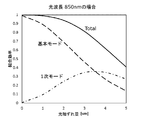
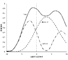
- FIG. 8 is a graph showing the simulation results of the coupling efficiency of optical power in that case.
- the horizontal axis represents the amount of optical axis deviation, and the vertical axis represents the coupling efficiency.
- the coupling efficiency becomes 1. Then, for example, when only 50% of the power is propagated into the optical fiber with respect to the input light, the coupling efficiency is 0.5.
- the basic mode (0th-order mode) component and the 1st-order mode component are described separately, and the sum of them forms a total curve. Since the input light has only the basic mode, it can be seen that the basic mode is converted to the primary mode according to the deviation. On the other hand, in the case of 1310 nm, since only the basic mode can propagate as shown in FIG. 3 (a), the basic mode is purely reduced as shown in FIG.
- the positions are about 1.8 times when compared at a bonding efficiency of 0.8 (about -1 dB) and about 2.35 times when compared at a bonding efficiency of 0.9 (about ⁇ 0.5 dB).
- the accuracy against deviation can be relaxed.
- the optical fiber can propagate only the basic mode at the first wavelength (for example, 1310 nm), and the light of the second wavelength (for example, 850 nm) that the optical fiber can propagate at least in the primary mode together with the basic mode. It is possible to increase the coupling efficiency of the optical power by configuring the communication using the above.
- the present technology is configured to perform communication using light having at least a primary mode component together with the basic mode.
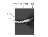
- FIG. 11 is a diagram simulating the intensity distribution of light transmitted in the optical fiber.
- FIG. 11A shows an example in which light having only the components of the basic mode is transmitted. In this case, the center of the core of the optical fiber has the highest strength, and the closer to the clad, the lower the strength.
- FIG. 11B shows an example of transmitting light having components of the basic mode and the primary mode. In this case, the high-strength portions appear alternately in one direction and the other direction with respect to the center of the core, and in the upward and downward directions in the illustrated example.
- FIG. 13A the light emitted from the center of the core 10a on the transmitting side is coupled to the center of the core 10a on the receiving side.
- FIG. 13B in the case of transmitting light having the components of the basic mode and the primary mode, the light whose intensity distribution is biased upward from the center of the core 10a on the transmitting side is received. It is connected downward with respect to the center of the core 10a on the side.
- the state shown in the figure is a state in which the amount of optical axis deviation is zero.
- the optical axis shift is in the positive (+) direction
- the portion having high light intensity is in the direction of entering the core 10a of the optical fiber 10R, so that it is easy to combine.
- the optical axis shift is in the negative ( ⁇ ) direction
- the core 10a of the optical fiber 10R moves in the direction opposite to the traveling direction of the light, so that the coupling efficiency is lowered.
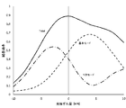
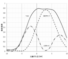
- FIG. 15 shows a simulation result of the coupling efficiency of optical power when the input light (light emitted from the transmitting side) has the components of the basic mode and the primary mode and the ratio is 1: 1. It is a graph.
- the horizontal axis represents the amount of optical axis deviation, and the vertical axis represents the coupling efficiency.
- the basic mode (0th-order mode) and the 1st-order mode are described separately, and the sum of them forms a total curve.
- the coupling efficiency drops significantly when the deviation is in the negative (-) direction, but thanks to the conversion of the basic mode to the primary mode component, the coupling efficiency is 0 with a deviation amount of -1.5 ⁇ m. It is about 7.
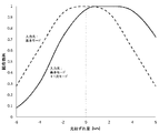
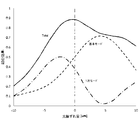
- FIG. 17 is a graph showing simulation results of optical power coupling efficiency when the input light has only the basic mode component and when the input light has the basic mode and primary mode components.
- the horizontal axis represents the amount of optical axis deviation, and the vertical axis represents the coupling efficiency.
- the bonding efficiency at the location where the strength is maximized is standardized as 1.
- the coupling efficiency is better than when the input light has only the components of the basic mode. This is because, as described above, when the optical axis deviation is in the positive (+) direction, the portion having high light intensity is in the direction of entering the core 10a of the optical fiber 10R, so that it is easy to combine.
- the coupling efficiency is worse when the optical axis shift is in the negative (-) direction than when the input light has only the components of the basic mode. .. This is because the core 10a of the optical fiber 10R moves in the direction opposite to the traveling direction of the light as described above.
- the coupling efficiency of the optical power with respect to the optical axis deviation in the negative (-) direction is configured to include an optical path adjusting unit that adjusts the optical path so as to guide the input light to the core of the optical waveguide.
- FIG. 18 shows an example in which a lens (convex lens) 12R as an optical path adjusting portion is provided on the incident side of the optical fiber 10R.
- a lens convex lens
- FIG. 18 shows an example in which a lens (convex lens) 12R as an optical path adjusting portion is provided on the incident side of the optical fiber 10R.
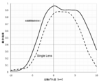
- FIG. 19 is a graph showing simulation results of optical power coupling efficiency in the case of a double lens (DoubleLens) provided with a lens 12R and in the case of a single lens (SingleLens) not provided with a lens 12R.
- the horizontal axis represents the amount of optical axis deviation
- the vertical axis represents the coupling efficiency. With respect to the optical axis shift in the negative (-) direction, the coupling efficiency of the double lens is higher than that of the single lens.
- the basic mode (0th-order mode) component and the 1st-order mode component are described separately, and the sum of them forms a total curve. ..
- the reason why the coupling efficiency of the double lens is higher than that of the single lens with respect to the optical axis deviation in the negative (-) direction is as follows. That is, even if the optical fiber 10R is displaced in the negative (-) direction by returning the light in the optical axis direction, the light is directed toward the center of the fiber, which has the effect of reducing the loss in the basic mode as compared with the single lens. This is due to the effect of increasing the rate at which the basic mode is converted to the primary mode. Comparing the case of the coupling efficiency of 0.7, it is ⁇ 1.5 ⁇ m for the single lens and -4 ⁇ m for the double lens, and it can be seen that the accuracy can be relaxed 2.7 times. Therefore, the accuracy of the double lens can be relaxed and the cost of parts can be reduced.
- FIG. 21 is an example in which the optical path adjusting member 13R is provided on the incident side of the optical fiber 10R.
- the optical path adjusting member 13R includes a central portion 13R_1 having a tapered surface 13a whose diameter gradually narrows toward the core 10a of the optical fiber 10R, and an outer peripheral portion 13R_2 around the central portion 13R_1.
- the central portion 13R_1 is composed of the same member as the core 10a of the optical fiber 10R
- the outer peripheral portion 13R_2 is composed of the same member as the clad 10b of the optical fiber 10R.
- the optical path adjusting member 13R By providing the optical path adjusting member 13R on the incident side of the optical fiber 10R in this way, light that deviates downward with respect to the optical axis can be reflected by the tapered surface 13a toward the optical axis side and returned to the center direction of the optical axis. it can. As a result, as in the case of the double lens described above, the coupling efficiency of the optical power can be increased with respect to the optical axis deviation in the negative ( ⁇ ) direction.
- FIG. 22 is a graph showing simulation results of optical power coupling efficiency in the case where the optical path adjusting member 13R is provided and in the case of a single lens (Single Lens) in which the optical path adjusting member 13R is not provided.
- the horizontal axis represents the amount of optical axis deviation
- the vertical axis represents the coupling efficiency.
- the optical path adjusting member 13R is provided for the optical axis deviation in the negative ( ⁇ ) direction
- the coupling efficiency is higher than that of the single lens.
- the basic mode (0th mode) component and the primary mode component are described separately, and the sum of them is the total. It becomes a curve of.
- FIG. 24 shows a case where the input light has only the basic mode component and the optical path adjusting member 13R is not provided (dashed line), and a case where the input light has only the basic mode component and the optical path adjusting member 13R is provided (broken line).
- the horizontal axis represents the amount of optical axis deviation, and the vertical axis represents the coupling efficiency.
- the bonding efficiency at the location where the strength is maximized is standardized as 1.
- the coupling efficiency is better when the optical path adjusting member 13R is provided than when the optical path adjusting member 13R is not provided. This is because the light deviating from the core 10a has a function of returning to the core 10a by the tapered surface 13a.
- the optical path adjusting member 13R When the optical path adjusting member 13R is provided and the input light has only the components of the basic mode or the components of the basic mode and the primary mode, the basic mode and the components of the primary mode are compared.
- the coupling efficiency is better with respect to the axial deviation in the positive (+) direction than when having only the mode component. This is because, when the light is deviated in the positive (+) direction, the portion having high light intensity is likely to be incident on the core 10a side of the optical fiber 10R.
- the size of the mouth on the incident end side of the tapered surface 13a is larger than the size of the core 10a, so that light traveling in a direction deviating from the core 10a It can be seen that the tapered surface 13a picks up the input light to the same extent as in the basic mode.
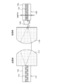
- FIG. 25 is an example in which the optical path adjusting member 14R is provided between the core 10a and the clad 10b at the incident end of the optical fiber 10R.
- the optical path adjusting member 14R has a tapered surface 14a whose diameter gradually narrows toward the core 10a as a surface in contact with the clad 10b, and a cylindrical surface 14b as a surface in contact with the core 10a.
- the cylindrical surface 14b has the same refractive index as the core 10a
- the tapered surface 14a has the same refractive index as the clad 10b
- the light path adjusting member 14R By providing the optical path adjusting member 14R between the core 10a and the clad 10b at the incident end of the optical fiber 10R in this way, the light path adjusting member 14R having the tapered surface 14a allows the light deviating downward with respect to the optical axis. It can be reflected to the optical axis side and returned to the center direction of the optical axis, and as in the case of the above-mentioned double lens, the coupling efficiency of optical power can be increased against the optical axis deviation in the negative (-) direction. ..
- FIG. 26 is a graph showing simulation results of optical power coupling efficiency in the case where the optical path adjusting member 14R is provided and in the case of a single lens (Single Lens) in which the optical path adjusting member 14R is not provided.
- the horizontal axis represents the amount of optical axis deviation
- the vertical axis represents the coupling efficiency.
- the optical path adjusting member 14R is provided for the optical axis deviation in the negative ( ⁇ ) direction
- the coupling efficiency is higher than that of the single lens.
- the basic mode (0th mode) component and the primary mode component are described separately, and the sum of them is the total. It becomes a curve of.
- the configuration of the optical path adjusting member 13R provided at the incident end of the optical fiber 10R of FIG. 21 may be the same as that of the incident end of the optical fiber 10R of FIG. It is conceivable that the configuration of the incident end of the fiber 10R is the same as that of the optical path adjusting member 13R provided at the incident end of the optical fiber 10R of FIG.
- FIG. 28 is an example in which the optical path adjusting member 21R is provided between the core 10a and the clad 10b at the incident end of the optical fiber 10R.
- the optical path adjusting member 21R has a tapered surface 21a whose diameter gradually expands from the core 10a as a surface in contact with the clad 10b, and a cylindrical surface 21b as a surface in contact with the core 10a.
- the cylindrical surface 21b has the same refractive index as the core 10a
- the tapered surface 21a has the same refractive index as the clad 10b
- the optical path adjusting member 21R between the core 10a at the incident end of the optical fiber 10R and the clad 10b in this way, even if the optical axis is deviated downward or upward, the light is tapered via the clad 10b. It can enter the portion and be further coupled to the core 10a. As a result, as in the case of the double lens described above, the coupling efficiency of the optical power can be increased with respect to the optical axis deviation in the negative ( ⁇ ) direction.
- FIG. 29 is a graph showing simulation results of optical power coupling efficiency in the case where the optical path adjusting member 21R is provided and in the case of a single lens (Single Lens) in which the optical path adjusting member 21R is not provided.
- the horizontal axis represents the amount of optical axis deviation
- the vertical axis represents the coupling efficiency.
- the optical path adjusting member 21R is provided for the optical axis deviation in the negative ( ⁇ ) direction
- the coupling efficiency is higher than that of the single lens.
- the basic mode (0th mode) component and the primary mode component are described separately, and the sum of them is the total. It becomes a curve of.
- the configuration of the optical path adjusting member 13R provided at the incident end of the optical fiber 10R of FIG. 21 is the same as that of the incident end of the optical fiber 10R of FIG. 28.
- FIG. 31 is an example in which the optical path adjusting member 22R is provided on the incident side of the optical fiber 10R.
- the optical path adjusting member 22R is a member having a refractive index distribution.
- the refractive index of the optical path adjusting member 22R has a refractive index equivalent to that of the core 10a of the optical fiber 10R on the optical axis, and has a gradation structure in which the refractive index decreases as the distance from the optical axis increases in the vertical direction.
- the optical path adjusting member 22R By providing the optical path adjusting member 22R on the incident side of the optical fiber 10R in this way, the light entering the optical path adjusting member 22R travels while bending in the optical axis direction due to the gradation effect. Further, even if the optical axis is deviated, the light can be returned toward the center. The reason is that when the optical path shifts downward with respect to the optical axis as shown by the broken line in FIG. 32, the light near the optical axis bends less because the difference in refractive index is small, and the light deviates from the optical axis. This is because the amount of bending is large because the difference in refractive index is large, and therefore the light is collected near the center of the core 10a. As a result, as in the case of the double lens described above, it is possible to increase the coupling efficiency of the optical power with respect to the optical axis deviation in the negative ( ⁇ ) direction.
- FIG. 33 is a graph showing simulation results of optical power coupling efficiency in the case where the optical path adjusting member 22R is provided and in the case of a single lens (Single Lens) in which the optical path adjusting member 22R is not provided.
- the horizontal axis represents the amount of optical axis deviation
- the vertical axis represents the coupling efficiency.
- the optical path adjusting member 22R is provided for the optical axis deviation in the negative ( ⁇ ) direction
- the coupling efficiency is higher than that of the single lens.
- the basic mode (0th mode) component and the primary mode component are described separately, and the sum of them is the total. It becomes a curve of.
- FIG. 35 is an example in which the optical path adjusting member 19R is provided on the incident side of the optical fiber 10R.
- the optical path adjusting member 19R is a member having a funnel-shaped space 19b having a tapered surface 19a whose diameter gradually narrows toward the core 10a of the optical fiber 10R.
- a mirror is arranged on the tapered surface 19a in order to totally reflect the input light. Regarding this mirror, it is conceivable not only to fix the separately generated mirror to the tapered surface 19a, but also to form the mirror on the tapered surface 19a by thin film deposition or the like.
- the optical path adjusting member 19R By providing the optical path adjusting member 19R on the incident side of the optical fiber 10R in this way, light that deviates downward with respect to the optical axis can be reflected by the tapered surface 19a toward the optical axis side and returned to the center direction of the optical axis. it can. As a result, as in the case of the double lens described above, the coupling efficiency of the optical power can be increased with respect to the optical axis deviation in the negative ( ⁇ ) direction.
- the funnel-shaped space 19b has a bottom portion, but it is conceivable that the bottom portion is eliminated to form a through hole.
- FIG. 36 shows a transmission / reception system 100 as an embodiment.
- the transmission / reception system 100 includes a transmitter 200, a receiver 300, and a cable 400.
- the transmitter 200 is, for example, an AV source such as a personal computer, a game machine, a disc player, a set-top box, a digital camera, or a mobile phone.
- the receiver 300 is, for example, a television receiver, a projector, or the like.
- the transmitter 200 and the receiver 300 are connected via a cable 400.
- the transmitter 200 has a light emitting unit 201, a connector 202 as a receptacle, and an optical fiber 203 that propagates the light emitted by the light emitting unit 201 to the connector 202.
- the light emitting unit 201 includes a laser element such as a VCSEL (Vertical Cavity Surface Emitting LASER) or a light emitting element such as an LED (light emission diode).
- the light emitting unit 201 converts an electric signal (transmission signal) generated by a transmission circuit (not shown) into an optical signal.
- the optical signal emitted by the light emitting unit 201 is propagated to the connector 202 through the optical fiber 203.
- the receiver 300 has a connector 301 as a receptacle, a light receiving unit 302, and an optical fiber 303 that propagates the light obtained by the connector 301 to the light receiving unit 302.
- the light receiving unit 302 includes a light receiving element such as a photodiode.
- the light receiving unit 302 converts an optical signal sent from the connector 301 into an electric signal (received signal) and supplies it to a receiving circuit (not shown).
- the cable 400 is configured to have connectors 402 and 403 as plugs at one end and the other end of the optical fiber 401.
- the connector 402 at one end of the optical fiber 401 is connected to the connector 202 of the transmitter 200, and the connector 403 at the other end of the optical fiber 401 is connected to the connector 301 of the receiver 300.
- the optical fiber 203 of the transmitter 200, the optical fiber 303 of the receiver 300, and the optical fiber 401 of the cable 400 propagate only in the basic mode at the first wavelength. Further, these optical fibers are configured so that the wavelength dispersion becomes zero at the first wavelength.
- the first wavelength is 1310 nm
- these optical fibers function as single-mode fibers at a wavelength of 1310 nm (see FIG. 3).
- communication is performed using light having a second wavelength and at least a primary mode component together with the basic mode.
- the second wavelength is a wavelength at which each of the above-mentioned optical fibers can propagate at least the primary mode together with the basic mode.
- the second wavelength is 850 nm.
- the 850 nm light (having the components of the basic mode and the primary mode) emitted by the light emitting unit 201 is propagated to the connector 202 by the optical fiber 203 which is a 1310 nm single mode fiber.
- the portion of the connector 402 is provided with an optical path adjusting unit that adjusts the optical path so as to guide the input light to the core of the optical fiber 401.
- the optical path adjusting unit includes, for example, the lens 12R shown in FIG. 18, the optical path adjusting member 13R shown in FIG. 21, the optical path adjusting member 14R shown in FIG. 25, the optical path adjusting member 21R shown in FIG. 28, and the optical path adjusting member 22R shown in FIG. , The optical path adjusting member 19R shown in FIG. 35 and the like.
- the 850 nm light (having the components of the basic mode and the primary mode) emitted from the connector 202 is coupled to the core of the optical fiber 401, which is a 1310 nm single mode fiber, and propagates to the receiver 300 side through the optical path adjustment unit. Will be done.
- the input light that does not go from the connector 202 to the core of the optical fiber 401 of the connector 402 is optical path adjusted by the optical path adjusting unit and guided to the core of the optical fiber 401, and at this time, light having a wavelength of 850 nm is used. Since the incident angle that can be transmitted by the optical fiber 401 is wider than when light having a wavelength of 1310 nm is used, the coupling loss of optical power can be reduced. Further, in this case, when there is an optical axis shift of the light incident on the optical fiber 401, the primary mode generated by the optical axis shift is propagated together with the basic mode, so that the coupling loss of the optical power is reduced. It is possible to reduce the accuracy of misalignment and reduce costs.
- the connector 301 is provided with an optical path adjusting unit that adjusts the optical path so as to guide the input light to the core of the optical fiber 303. Then, the 850 nm light (having the components of the basic mode and the primary mode) emitted from the connector 403 is coupled to the core of the optical fiber 303, which is a 1310 nm single mode fiber, to the light receiving unit 302 through the optical path adjusting unit. Propagate.
- FIG. 37 is a perspective view showing a configuration example of the connector 202 of the transmitter 200 and the connector 402 of the cable 400.
- FIG. 38 is also a perspective view showing a configuration example of the connector 202 of the transmitter 200 and the connector 402 of the cable 400, but is a view seen from the direction opposite to that of FIG. 37.
- the illustrated example corresponds to the parallel transmission of optical signals of a plurality of channels, but although detailed description thereof will be omitted, the example corresponding to the transmission of optical signals of one channel can be similarly configured.
- the optical path adjusting portion provided in the portion of the connector 402 is a lens (see FIG. 18) will be described.
- the connector 202 includes a connector body (ferrule) 211 having a substantially rectangular parallelepiped appearance.
- a plurality of optical fibers 203 corresponding to each channel are connected to the back side of the connector main body 211 in a horizontally arranged state. The tip side of each optical fiber 203 is inserted into the optical fiber insertion hole 216 and fixed.
- an adhesive injection hole 212 having a rectangular opening is formed on the upper surface side of the connector main body 211. An adhesive for fixing the optical fiber 203 to the connector main body 211 is injected from the adhesive injection hole 212.
- a concave light emitting portion (light transmission space) 213 having a rectangular opening is formed on the front side of the connector main body 211, and the bottom portion of the light emitting portion 213 corresponds to each channel.
- a plurality of lenses (convex lenses) 214 are formed in a state of being arranged in the horizontal direction. As a result, the surface of the lens 214 is prevented from being inadvertently hit by the connector or the like on the other side and being damaged.
- a convex or concave position restricting portion 215 for aligning with the connector 402, or concave in the illustrated example, is integrally formed. As a result, the optical axis alignment at the time of connection with the connector 402 can be easily performed.
- the connector 402 includes a connector body 411 having a substantially rectangular parallelepiped appearance.
- the connector main body 411 is configured by connecting a first optical unit 412 and a second optical unit (ferrule) 413. Since the connector main body 411 is composed of the first optical unit 412 and the second optical unit 413 in this way, although not shown in FIGS. 37 and 38, a second lens as an optical path adjusting unit ( Convex lenses) can be easily manufactured.
- a concave light incident portion (light transmission space) 415 having a rectangular opening is formed on the front surface side of the first optical portion 412, and the bottom portion of the light incident portion 415 corresponds to each channel.
- a plurality of first lenses (convex lenses) 416 are formed in a state of being arranged in the horizontal direction. As a result, the surface of the first lens 416 is prevented from being inadvertently hit by the connector or the like on the other side and being damaged.
- a convex or concave position restricting portion 417 for aligning with the connector 202, or a convex position regulating portion 417 in the illustrated example is integrally formed.
- the position regulating unit 417 is not limited to the one integrally formed with the first optical unit 412, and a pin may be used or another method may be used. ..
- a plurality of optical fibers 401 corresponding to each channel are connected to the back side of the second optical unit 413 in a horizontally arranged state.
- the tip side of each optical fiber 401 is inserted into the optical fiber insertion hole 418 and fixed.
- an adhesive injection hole 414 having a rectangular opening is formed on the upper surface side of the second optical unit 413. An adhesive for fixing the optical fiber 401 to the second optical unit 413 is injected from the adhesive injection hole 414.
- FIG. 39A is a cross-sectional view showing an example of the connector 202 of the transmitter 200.
- the position regulating unit 215 (see FIG. 37) is not shown.
- the connector 202 will be further described with reference to FIG. 39 (a).
- the connector 202 includes a connector main body 211.
- the connector main body 211 is made of a light-transmitting material such as synthetic resin or glass, or a material such as silicon that transmits a specific wavelength, and has a ferrule with a lens.
- the connector body 211 By configuring the connector body 211 as a ferrule with a lens in this way, it is possible to easily align the optical axis between the optical fiber and the lens. Further, since the connector main body 211 is configured as a ferrule with a lens in this way, even in the case of multiple channels, multi-channel communication can be easily realized simply by inserting the optical fiber into the ferrule.
- the connector main body 211 is formed with a concave light emitting portion (light transmission space) 213 on the front side thereof. Then, the connector main body 211 is integrally formed with lenses (convex lenses) 214 corresponding to each channel arranged in the horizontal direction so as to be located at the bottom portion of the light emitting portion 213. As a result, the positional accuracy of the lens 214 with respect to the core 203a of the optical fiber 203 installed in the connector main body 211 can be improved at the same time in a plurality of channels.
- the connector main body 211 is provided with a plurality of optical fiber insertion holes 216 extending forward from the back side in a state of being arranged in the horizontal direction in accordance with the lens 214 of each channel.
- the optical fiber 203 has a double structure consisting of a core 203a in a central portion serving as an optical path and a clad 203b covering the periphery thereof.
- the optical fiber insertion holes 216 of each channel are formed so that the optical axes of the lens 214 corresponding to the core 203a of the optical fiber 203 inserted therein coincide with each other. Further, the optical fiber insertion holes 216 of each channel are formed so that the bottom position thereof, that is, the contact position of the tip (incident end) of the optical fiber 203 when inserted, matches the focal position of the lens 214. ing.
- the connector main body 211 is formed so that adhesive injection holes 212 extending downward from the upper surface side communicate with each other near the bottom positions of a plurality of optical fiber insertion holes 216 arranged in the horizontal direction. .. After the optical fiber 203 is inserted into the optical fiber insertion hole 216, the adhesive 217 is injected around the optical fiber 203 from the adhesive injection hole 212, so that the optical fiber 203 is fixed to the connector main body 211.
- the lens 214 has a function of molding the light emitted from the optical fiber 203 into collimated light and emitting the light. As a result, the light emitted from the exit end of the optical fiber 203 is incident on the lens 214, formed into collimated light, and emitted.
- FIG. 39B is a cross-sectional view showing an example of the connector 402 of the cable 400.
- the position regulating unit 417 (see FIGS. 37 and 38) is not shown.
- the connector 402 will be further described with reference to FIG. 39 (b).
- the connector 402 includes a connector main body 411 configured by connecting the first optical unit 412 and the second optical unit 413.
- the first optical unit 412 is made of a light-transmitting material such as synthetic resin or glass, or a material such as silicon that transmits a specific wavelength.
- a concave light incident portion (light transmission space) 415 is formed on the front surface side of the first optical portion 412.
- the first lens 416 corresponding to each channel is integrally formed on the first optical unit 412 in a state of being arranged in the horizontal direction so as to be located at the bottom portion of the light incident portion 415. There is. As a result, the positional accuracy of the first lens 416 with respect to the first optical unit 412 can be improved.
- a concave space 420 is formed on the back side of the first optical unit 412. This space 420 is sealed on the front side of the second optical unit 413 to form a closed space.
- the second lens 421 of each channel formed on the front surface side of the second optical unit 413 is in a state of being located in this enclosed space.
- the second optical unit 413 is made of a light-transmitting material such as synthetic resin or glass, or a material such as silicon that transmits a specific wavelength, and is configured as a ferrule with a lens. As described above, the second optical unit 413 is connected to the first optical unit 412 to form the connector main body 411.
- the material of the second optical unit 413 is the same as that of the material of the first optical unit 412 because the optical path shift due to distortion in the two optical units when the heat changes can be suppressed by aligning the coefficients of thermal expansion. It is preferably present, but it may be a different material.
- the second optical unit 413 is configured as a ferrule with a lens in this way, the optical axis of the optical fiber 401 and the second lens 421 can be easily aligned. Further, since the second optical unit 413 is configured as a ferrule with a lens in this way, even in the case of multiple channels, multi-channel communication can be easily realized simply by inserting the optical fiber 401 into the ferrule.
- the second optical unit 413 is integrally formed with the second lens 421 corresponding to each channel arranged in the horizontal direction on the front surface side thereof. As a result, the positional accuracy of the second lens 421 with respect to the core 401a of the optical fiber 401 installed in the second optical unit 413 can be improved at the same time in a plurality of channels.
- the second optical unit 413 is provided with a plurality of optical fiber insertion holes 418 extending forward from the back side in a state of being arranged in the horizontal direction in accordance with the second lens 421 of each channel.
- the optical fiber 401 has a double structure consisting of a core 401a at the center of the optical path and a clad 401b covering the periphery thereof.
- the optical fiber insertion hole 418 of each channel is formed so that the core 401a of the optical fiber 401 inserted therein and the optical axis of the corresponding second lens 421 coincide with each other. Further, the optical fiber insertion hole 418 of each channel has its bottom position, that is, when the optical fiber 401 is inserted, the contact position of the tip (incident end) of the optical fiber insertion hole 418 matches the focal position of the second lens 421. , Molded.
- adhesive injection holes 414 extending downward from the upper surface side are formed so as to communicate with each other near the bottom positions of a plurality of optical fiber insertion holes 418 arranged in the horizontal direction. Has been done. After the optical fiber 401 is inserted into the optical fiber insertion hole 418, the adhesive 419 is injected around the optical fiber 401 from the adhesive injection hole 414, whereby the optical fiber 401 is fixed to the second optical unit 413. To.
- the first optical unit 412 and the second optical unit 413 are connected to form the connector main body 411.
- this connection method a method of newly providing a concave portion on one side and a convex portion on the other side such as a boss to fit the lens, or a method of aligning the optical axis positions of the lenses with each other and fixing them by adhesion using an image processing system or the like is adopted. obtain.
- the first lens 416 has a function of collecting the incident collimated light.
- the second lens 421 has a function of adjusting the optical path so as to guide the incident light to the core 401a of the optical fiber 401 (see FIG. 18).
- the collimated light is incident on the first lens 416 and condensed, and the condensed light is incident on the incident end of the optical fiber 401 through the second lens 421.
- FIG. 40 shows a cross-sectional view of a state in which the connector 202 of the transmitter 200 and the connector 402 of the cable 400 are connected.
- the light transmitted through the optical fiber 203 is emitted from the exit end of the optical fiber 203 with a predetermined NA.
- the emitted light is incident on the lens 214, formed into collimated light, and emitted toward the connector 402.
- the light emitted from the connector 202 is incident on the first lens 416 and condensed. Then, the collected light is incident on the incident end of the optical fiber 401 through the second lens 421 and sent through the optical fiber 401.
- the connector 403 of the cable 400 and the connector 301 of the receiver 300 in FIG. 36 are configured in the same manner as the configuration example of the connector 202 of the transmitter 200 and the connector 402 of the cable 400 described above.
- the first wavelength is set to 1310 nm, but since a laser light source or an LED light source can be used as the light source, the first wavelength is, for example, between 300 nm and 5 ⁇ m. It is possible that there is.
- the first wavelength has been described as 1310 nm, but it is also conceivable that the first wavelength is a wavelength in the 1310 nm band including 1310 nm. Further, in the above-described embodiment, the first wavelength has been described as 1310 nm, but it is also conceivable that the first wavelength is a wavelength in the 1550 nm band including 1550 nm or 1550 nm. Further, although the second wavelength has been described as 850 nm, it is also conceivable that the second wavelength is a wavelength in the 850 nm band including 850 nm.
- the optical waveguide is an optical fiber
- this technique can be applied to an optical waveguide other than the optical fiber, such as a silicon optical waveguide.
- the present technology may have the following configurations.
- An optical waveguide that propagates only the basic mode at the first wavelength is provided. Communicate using light having a second wavelength and at least a primary mode component together with the basic mode.
- the second wavelength is an optical communication device in which the optical waveguide can propagate at least the primary mode together with the basic mode.
- the optical communication device according to (1) above further comprising an optical path adjusting unit that adjusts an optical path so as to guide input light to the core of the optical waveguide.
- the optical path adjusting unit adjusts an optical path by utilizing refraction by a lens.
- optical path adjusting unit adjusts the optical path by utilizing reflection by an optical path adjusting member having a tapered surface whose aperture gradually narrows toward the incident side of the optical waveguide.
- Communication device (5)
- the optical path adjusting portion is provided between the core and the clad at the incident end of the optical waveguide, and the surface in contact with the clad gradually expands from the same diameter as the core and from the core to the above.
- the optical communication device wherein the optical path is adjusted by using an optical path adjusting member whose refractive index gradually changes from the same refractive index as that of the core toward the clad to the same refractive index as that of the clad.
- the optical path adjusting unit is provided on the incident side of the optical waveguide, has a refractive index equivalent to that of the core of the optical waveguide on the optical axis, and has a gradient structure in which the refractive index decreases as the distance from the optical axis increases in the vertical direction.
- the first wavelength is a wavelength at which the wavelength dispersion becomes zero.
- the optical communication device (9) The optical communication device according to (8) above, wherein the first wavelength is a wavelength in the 1310 nm band or the 1550 nm band. (10) The optical communication device according to any one of (1) to (9) above, wherein the second wavelength is a wavelength in the 850 nm band. (11) The optical communication device according to any one of (1) to (10) above, wherein the optical waveguide is an optical fiber. (12) The optical communication device according to any one of (1) to (10) above, wherein the optical waveguide is a silicon optical waveguide. (13) In an optical communication device provided with an optical waveguide that propagates only in the basic mode at the first wavelength, communication is performed using light having a second wavelength and at least a primary mode component together with the basic mode.
- the second wavelength is an optical communication method in which the optical waveguide can propagate at least the primary mode together with the basic mode.
- the second wavelength is an optical communication system in which the optical waveguide can propagate at least the primary mode together with the basic mode.
- the transmitter is a receptacle of a transmitter or a plug of a cable.
Landscapes
- Physics & Mathematics (AREA)
- General Physics & Mathematics (AREA)
- Optics & Photonics (AREA)
- Electromagnetism (AREA)
- Engineering & Computer Science (AREA)
- Computer Networks & Wireless Communication (AREA)
- Signal Processing (AREA)
- Chemical & Material Sciences (AREA)
- Dispersion Chemistry (AREA)
- Optical Couplings Of Light Guides (AREA)
Abstract
La présente invention peut faciliter la précision par rapport au déplacement et réduire ainsi les coûts. La communication est effectuée à l'aide d'une lumière ayant une seconde longueur d'onde et ayant un composant ayant un mode fondamental et au moins un mode primaire. Ici, la seconde longueur d'onde est une longueur d'onde à laquelle un guide d'ondes optique peut propager le mode fondamental conjointement avec au moins le mode primaire. Par exemple, la présente invention est pourvue d'une unité de réglage de trajet de lumière qui règle un trajet de lumière de telle sorte que la lumière d'entrée est guidée vers le coeur du guide d'ondes optique.
Priority Applications (1)
| Application Number | Priority Date | Filing Date | Title |
|---|---|---|---|
| US17/434,246 US11716146B2 (en) | 2019-03-08 | 2020-02-18 | Optical communication apparatus, optical communication method, and optical communication system |
Applications Claiming Priority (4)
| Application Number | Priority Date | Filing Date | Title |
|---|---|---|---|
| JP2019042477 | 2019-03-08 | ||
| JP2019-042477 | 2019-03-08 | ||
| JP2019-104082 | 2019-06-04 | ||
| JP2019104082 | 2019-06-04 |
Publications (1)
| Publication Number | Publication Date |
|---|---|
| WO2020184094A1 true WO2020184094A1 (fr) | 2020-09-17 |
Family
ID=72427312
Family Applications (1)
| Application Number | Title | Priority Date | Filing Date |
|---|---|---|---|
| PCT/JP2020/006380 Ceased WO2020184094A1 (fr) | 2019-03-08 | 2020-02-18 | Dispositif de communication optique, procédé de communication optique et système de communication optique |
Country Status (2)
| Country | Link |
|---|---|
| US (1) | US11716146B2 (fr) |
| WO (1) | WO2020184094A1 (fr) |
Cited By (7)
| Publication number | Priority date | Publication date | Assignee | Title |
|---|---|---|---|---|
| JPWO2021095702A1 (fr) * | 2019-11-13 | 2021-05-20 | ||
| WO2021145246A1 (fr) * | 2020-01-17 | 2021-07-22 | ソニーグループ株式会社 | Dispositif, procédé et système de communication optique, dispositif de transmission de lumière, dispositif de réception de lumière, dispositif et procédé de réglage d'intervalle de longueur d'onde |
| JP2021121089A (ja) * | 2020-01-31 | 2021-08-19 | ソニーグループ株式会社 | 光受信装置、波長幅調整装置および波長幅調整方法 |
| JP2021120732A (ja) * | 2020-01-31 | 2021-08-19 | ソニーグループ株式会社 | 光送信装置、波長幅調整装置および波長幅調整方法 |
| WO2023042448A1 (fr) * | 2021-09-16 | 2023-03-23 | ソニーグループ株式会社 | Système et procédé de communication optique, récepteur, guide d'ondes optiques et émetteur |
| WO2023100607A1 (fr) * | 2021-11-30 | 2023-06-08 | ソニーグループ株式会社 | Structure d'interface, connecteur optique, émetteur, récepteur, câble optique et système de communication optique |
| WO2023195280A1 (fr) * | 2022-04-07 | 2023-10-12 | ソニーグループ株式会社 | Câble optique, dispositif électronique et système de communication optique |
Families Citing this family (1)
| Publication number | Priority date | Publication date | Assignee | Title |
|---|---|---|---|---|
| EP4471399A4 (fr) * | 2022-01-28 | 2025-05-07 | Sony Group Corporation | Dispositif de détermination, procédé de détermination et programme |
Citations (4)
| Publication number | Priority date | Publication date | Assignee | Title |
|---|---|---|---|---|
| JP2004286959A (ja) * | 2003-03-20 | 2004-10-14 | Tdk Corp | 光導波路の製造方法および光導波路 |
| JP2005049768A (ja) * | 2003-07-31 | 2005-02-24 | Fujitsu Ltd | 光学素子及び光接続構造 |
| WO2005114278A1 (fr) * | 2004-05-21 | 2005-12-01 | Matsushita Electric Industrial Co., Ltd. | Élément optique du type à répartition d'indice de réfraction et procédé de fabrication pour un élément optique de type à répartition d'indice de réfraction |
| WO2018027267A1 (fr) * | 2016-08-09 | 2018-02-15 | Macquarie University | Système et procédé de détection de l'installation d'un robinet optique et procédé de fixation d'un signal optique dans une fibre optique |
Family Cites Families (7)
| Publication number | Priority date | Publication date | Assignee | Title |
|---|---|---|---|---|
| EP1426799A3 (fr) * | 2002-11-29 | 2005-05-18 | Matsushita Electric Industrial Co., Ltd. | Démultiplexeur optique, multiplexeur/démultiplexeur optique, et dispositif optique |
| FR2932932B1 (fr) * | 2008-06-23 | 2010-08-13 | Draka Comteq France Sa | Systeme optique multiplexe en longueur d'ondes avec fibres optiques multimodes |
| US8891964B2 (en) * | 2011-12-12 | 2014-11-18 | Nec Laboratories America, Inc. | Dynamic multidimensional optical networking based on spatial and spectral processing |
| US9197356B2 (en) * | 2012-11-16 | 2015-11-24 | At&T Intellectual Property I, L.P. | Distributed spatial mode processing for spatial-mode multiplexed communication systems |
| KR20150012131A (ko) * | 2013-07-24 | 2015-02-03 | 한국전자통신연구원 | 다중 모드 광섬유 기반 광송수신 장치 |
| US10113935B2 (en) * | 2015-01-08 | 2018-10-30 | Nec Corporation | Distributed multi-channel coherent optical fiber sensing system |
| JP6784260B2 (ja) | 2015-09-30 | 2020-11-11 | ソニー株式会社 | 光通信コネクタ、光通信ケーブル及び電子機器 |
-
2020
- 2020-02-18 US US17/434,246 patent/US11716146B2/en active Active
- 2020-02-18 WO PCT/JP2020/006380 patent/WO2020184094A1/fr not_active Ceased
Patent Citations (4)
| Publication number | Priority date | Publication date | Assignee | Title |
|---|---|---|---|---|
| JP2004286959A (ja) * | 2003-03-20 | 2004-10-14 | Tdk Corp | 光導波路の製造方法および光導波路 |
| JP2005049768A (ja) * | 2003-07-31 | 2005-02-24 | Fujitsu Ltd | 光学素子及び光接続構造 |
| WO2005114278A1 (fr) * | 2004-05-21 | 2005-12-01 | Matsushita Electric Industrial Co., Ltd. | Élément optique du type à répartition d'indice de réfraction et procédé de fabrication pour un élément optique de type à répartition d'indice de réfraction |
| WO2018027267A1 (fr) * | 2016-08-09 | 2018-02-15 | Macquarie University | Système et procédé de détection de l'installation d'un robinet optique et procédé de fixation d'un signal optique dans une fibre optique |
Cited By (14)
| Publication number | Priority date | Publication date | Assignee | Title |
|---|---|---|---|---|
| JPWO2021095702A1 (fr) * | 2019-11-13 | 2021-05-20 | ||
| WO2021095702A1 (fr) * | 2019-11-13 | 2021-05-20 | ソニーグループ株式会社 | Module optique, dispositif de réglage et procédé de réglage |
| US12147077B2 (en) | 2019-11-13 | 2024-11-19 | Sony Group Corporation | Optical module, adjustment device, and adjustment method |
| JP7548242B2 (ja) | 2019-11-13 | 2024-09-10 | ソニーグループ株式会社 | 調整装置および調整方法 |
| WO2021145246A1 (fr) * | 2020-01-17 | 2021-07-22 | ソニーグループ株式会社 | Dispositif, procédé et système de communication optique, dispositif de transmission de lumière, dispositif de réception de lumière, dispositif et procédé de réglage d'intervalle de longueur d'onde |
| JP7409119B2 (ja) | 2020-01-31 | 2024-01-09 | ソニーグループ株式会社 | 光送信装置、波長幅調整装置および波長幅調整方法 |
| JP7459528B2 (ja) | 2020-01-31 | 2024-04-02 | ソニーグループ株式会社 | 光受信装置、波長幅調整装置および波長幅調整方法 |
| JP2021120732A (ja) * | 2020-01-31 | 2021-08-19 | ソニーグループ株式会社 | 光送信装置、波長幅調整装置および波長幅調整方法 |
| JP2021121089A (ja) * | 2020-01-31 | 2021-08-19 | ソニーグループ株式会社 | 光受信装置、波長幅調整装置および波長幅調整方法 |
| JPWO2023042448A1 (fr) * | 2021-09-16 | 2023-03-23 | ||
| WO2023042448A1 (fr) * | 2021-09-16 | 2023-03-23 | ソニーグループ株式会社 | Système et procédé de communication optique, récepteur, guide d'ondes optiques et émetteur |
| JP7816363B2 (ja) | 2021-09-16 | 2026-02-18 | ソニーグループ株式会社 | 光通信システム、光通信方法、受信機、光導波路および送信機 |
| WO2023100607A1 (fr) * | 2021-11-30 | 2023-06-08 | ソニーグループ株式会社 | Structure d'interface, connecteur optique, émetteur, récepteur, câble optique et système de communication optique |
| WO2023195280A1 (fr) * | 2022-04-07 | 2023-10-12 | ソニーグループ株式会社 | Câble optique, dispositif électronique et système de communication optique |
Also Published As
| Publication number | Publication date |
|---|---|
| US11716146B2 (en) | 2023-08-01 |
| US20220149942A1 (en) | 2022-05-12 |
Similar Documents
| Publication | Publication Date | Title |
|---|---|---|
| WO2020184094A1 (fr) | Dispositif de communication optique, procédé de communication optique et système de communication optique | |
| JP6956211B2 (ja) | 光コネクタ及び光コネクタシステム並びにこれらを備えたアクティブ光ケーブル | |
| JP7396304B2 (ja) | 光通信装置、光通信方法および光通信システム | |
| EP3640692B1 (fr) | Module de connecteur optique | |
| JP4586546B2 (ja) | マルチモード波長多重光トランシーバ | |
| US12013582B2 (en) | Optical communication apparatus, optical communication method, and optical communication system | |
| JP7548242B2 (ja) | 調整装置および調整方法 | |
| US20250012973A1 (en) | Interface structure, optical connector, transmitter, receiver, optical cable, and optical communication system | |
| JP7428140B2 (ja) | 光コネクタ、光ケーブルおよび電子機器 | |
| JP7740268B2 (ja) | 光導波路、光通信装置、光通信方法および光通信システム | |
| JP7409119B2 (ja) | 光送信装置、波長幅調整装置および波長幅調整方法 | |
| JP7459519B2 (ja) | 光通信装置、光通信方法および光通信システム | |
| WO2023013136A1 (fr) | Système de mesure, instrument de mesure et câble | |
| JP7816363B2 (ja) | 光通信システム、光通信方法、受信機、光導波路および送信機 | |
| WO2023195280A1 (fr) | Câble optique, dispositif électronique et système de communication optique | |
| JP7459528B2 (ja) | 光受信装置、波長幅調整装置および波長幅調整方法 | |
| WO2020039636A1 (fr) | Unité de connecteur optique et structure de connexion optique | |
| WO2021145246A1 (fr) | Dispositif, procédé et système de communication optique, dispositif de transmission de lumière, dispositif de réception de lumière, dispositif et procédé de réglage d'intervalle de longueur d'onde |
Legal Events
| Date | Code | Title | Description |
|---|---|---|---|
| 121 | Ep: the epo has been informed by wipo that ep was designated in this application |
Ref document number: 20770710 Country of ref document: EP Kind code of ref document: A1 |
|
| NENP | Non-entry into the national phase |
Ref country code: DE |
|
| 122 | Ep: pct application non-entry in european phase |
Ref document number: 20770710 Country of ref document: EP Kind code of ref document: A1 |
|
| NENP | Non-entry into the national phase |
Ref country code: JP |