WO2020121897A1 - Dispositif de surveillance, procédé de surveillance et dispositif de traitement de substrat - Google Patents
Dispositif de surveillance, procédé de surveillance et dispositif de traitement de substrat Download PDFInfo
- Publication number
- WO2020121897A1 WO2020121897A1 PCT/JP2019/047258 JP2019047258W WO2020121897A1 WO 2020121897 A1 WO2020121897 A1 WO 2020121897A1 JP 2019047258 W JP2019047258 W JP 2019047258W WO 2020121897 A1 WO2020121897 A1 WO 2020121897A1
- Authority
- WO
- WIPO (PCT)
- Prior art keywords
- grating
- opening
- unit
- monitoring device
- normal state
- Prior art date
- Legal status (The legal status is an assumption and is not a legal conclusion. Google has not performed a legal analysis and makes no representation as to the accuracy of the status listed.)
- Ceased
Links
Images


Classifications
-
- G—PHYSICS
- G08—SIGNALLING
- G08B—SIGNALLING SYSTEMS, e.g. PERSONAL CALLING SYSTEMS; ORDER TELEGRAPHS; ALARM SYSTEMS
- G08B21/00—Alarms responsive to a single specified undesired or abnormal condition and not otherwise provided for
- G08B21/18—Status alarms
- G08B21/24—Reminder alarms, e.g. anti-loss alarms
Definitions
- the present disclosure relates to a monitoring device, a monitoring method, and a substrate processing device.
- the technology according to the present disclosure improves the safety of workers when the grating in the clean room is removed and opened.
- One aspect of the present disclosure is a monitoring device that monitors a floor configured by grating in a clean room, and a communication unit that performs communication for detecting the position of the grating is attached to each grating.
- the monitoring device based on the detection result of the current position of the grating using the communication result with the communication unit, and information about the position of the grating in a normal state in which there is no opening caused by removing the grating, A determination unit that determines the presence or absence of the opening, and an output unit that outputs according to the determination result of the presence or absence of the opening in the determination unit.
- a large number of semiconductor manufacturing devices are arranged in a clean room in a clean atmosphere.
- a grating having a large number of lattice-like ventilation portions is arranged on the floor portion.
- pipes, various electric devices, pumps, chemical tanks, etc. are housed. For example, when the installation, maintenance, or breakdown of these pipes, various electric devices, pumps, and the like occurs, it is necessary for the worker to descend to the lower space of the grating to perform work, and thus the grating is removable.
- Patent Document 1 detects the presence or absence of an opening from which the grating is removed based on a surveillance camera that captures an image of the grating, and an image signal obtained by the surveillance camera, and when there is a worker. An alarm signal is output and an alarm is issued from an alarm generating means.
- the present disclosure provides a monitoring system that can be constructed at a lower cost.
- the monitoring device according to the embodiment will be described below.
- elements having substantially the same functional configuration are designated by the same reference numerals, and duplicate description will be omitted.
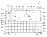
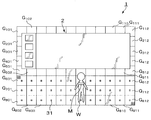
- FIG. 1 is a plan view showing the outline of the overall configuration of a monitoring system having a monitoring device according to the first embodiment.
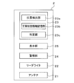
- FIG. 2 is a block diagram showing an outline of a configuration related to a monitoring process of the monitoring device according to the first embodiment.
- the monitoring system 1 of FIG. 1 monitors the floor constituted by the grating G in the clean room by a monitoring device.
- the substrate processing apparatus 2 On the floor to be monitored by the monitoring system 1, for example, the substrate processing apparatus 2 is placed.
- one of the four surfaces, for example, the back surface is located on the grating G 801 to the grating G 812 , and the front surface facing the one surface is on the G 501 to the grating G 512 .
- the substrate processing apparatus 2 On the floor, in the substrate processing apparatus 2, one of the four surfaces, for example, the back surface is located on the grating G 801 to the grating G 812 , and the front surface facing the one surface is on the G 501 to the grating G 512
- An RFID tag 31 as a communication unit that performs communication for detecting the position of the grating G is attached to each of the monitoring target gratings G.
- the RFID tag 31 is attached and attached to the center of the upper surface of the grating G, for example.
- the RFID tag 31 has a storage unit and an antenna (not shown), and the storage unit stores identification information unique to each RFID tag 31, that is, unique to each grating G.
- the RFID tag 31 configured as described above, when receiving a radio wave from an antenna 21 described later included in the substrate processing apparatus 2 that functions as a monitoring device, converts information such as identification information stored in the storage unit into a signal, The signal is transmitted from the antenna of the RFID tag 31.
- the antenna 21 emits a modulated wave (radio wave) to the RFID tag 31 for the purpose of reading the identification information of the RFID tag 31 or receives a signal wave from the RFID tag 31.
- one antenna 21 is attached to a top plate that forms a housing 2a that covers the substrate processing section of the substrate processing apparatus 2.
- a plurality of antennas 21 are provided.
- the grating G to be monitored is only on the front side of the substrate processing apparatus 2, but when the grating G around the entire substrate processing apparatus 2 is to be monitored, the grating G can be arranged in the front, rear, left, and right sides of the housing 2a.
- the reader/writer 22 is provided, for example, adjacent to the antenna 21, and drives the antenna 21.
- control unit 23 the position detection unit 23a, the normal state information storage unit 23b, and the determination unit 23c are mounted by the processing of the CPU according to the instruction of the program for realizing the monitoring processing.
- the normal state information storage unit 23b stores information regarding the position of the grating G in the normal state (hereinafter, may be referred to as "normal state information of the grating G").
- the normal state is a state in which the opening formed by removing the grating G does not exist on the floor of the monitoring target area.
- the determination unit 23c determines the floor monitoring target area based on the detection result of the current position of the grating G by the position detection unit 23a and the normal state information of the grating G stored in the normal state information storage unit 23b. Then, it is determined whether or not there is an opening due to the removal of the grating G.
- the alarm unit 24 and the display unit 25 are output units that output according to the determination result by the determination unit 23c as to whether or not the opening is present.
- the alarm unit 24 issues an alarm with at least one of light and sound.
- the audible alarm may be a form in which the audible alarm is violated or a form in which the warning message is read aloud.
- the alarm unit 24 is provided above the housing 2a of the substrate processing apparatus 2, for example.
- the display unit 25 displays various images, and is composed of, for example, a liquid crystal display, an organic EL display, or the like.
- the display unit 25 displays at least one of an image indicating the presence of the opening and an image indicating the position of the opening.
- the display unit 25 is provided on the front side of the substrate processing apparatus 2, for example.
- the normal state information of the grating G is acquired when the monitoring system 1 is installed.
- the position detection unit 23a controls the reader/writer 22 in a normal state in which neither of the gratings G has been removed and no opening is present.
- the position detection unit 23a changes the posture of the antenna 21 while transmitting radio waves through the antennas 21 for all RFID tags 31 and a signal wave including the above-described identification information that is a response wave to the radio waves. And receive.
- the position detection unit 23a detects the 3D position of each RFID tag 31 in the normal state based on the reception result, thereby detecting the 3D position of each grating G in the normal state.
- the information of these 3D positions is stored in the normal state information storage unit 23b as the normal state information of the grating G.
- the monitoring system 1 When the installation of the monitoring system 1 is completed, the monitoring system 1 operates as follows. That is, the position detection unit 23a controls the reader/writer 22 to change the attitude of the antenna 21 at regular intervals. As a result, the position detection unit 23a transmits the radio wave via the antenna 21 and the above-mentioned identification information, which is a response wave to the radio wave, for all the RFID tags 31 at regular intervals (for example, every one second). Reception of the signal wave containing it is performed. Then, the position detection unit 23a detects the current 3D position of each RFID tag 31 based on the reception result, thereby detecting the current 3D position of each grating G.
- the position detection unit 23a controls the reader/writer 22 to change the attitude of the antenna 21 at regular intervals.
- the position detection unit 23a transmits the radio wave via the antenna 21 and the above-mentioned identification information, which is a response wave to the radio wave, for all the RFID tags 31 at regular intervals (for example, every one second). Reception of
- the determination unit 23c determines whether the current position of each grating G matches the normal position based on the detection result of the position detection unit 23a and the normal state information stored in the normal state information storage unit 23b. Determine whether or not. Then, based on the determination result, the determination unit 23c determines the presence/absence of the opening.
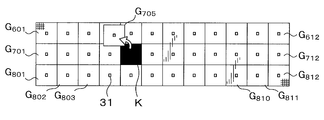
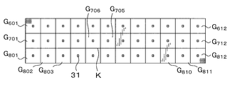
- the position detection unit 23a detects the current 3D position of each grating G at regular intervals, as described above.
- the determination unit 23c causes the current position of each grating G to coincide with the normal state position. To determine. Then, based on the determination result, the determination unit 23c determines whether or not the opening K is closed. For example, when the current positions of all the gratings G match the positions in the normal state, the determination unit 23c determines that the opening K is closed, and the alarm from the alarm unit 24 is stopped.
- the presence or absence of the opening is determined based on the detection result of the current position of the grating G using the communication result with the RFID tag 31 and the normal state information, and the output according to the determination result is performed. There is. Therefore, the worker on site can immediately know that the opening exists. Therefore, even during the work, it is possible to prevent the situation in which the user perceives that the opening exists while the alarm is being issued and performs the work, and accidentally falls from the opening. Further, the surveillance system of the present embodiment does not require expensive equipment such as a surveillance camera, and thus can be constructed at low cost.
- the construction of the monitoring system of the present embodiment can be performed by sequentially attaching the RFID tags 31 on the grating G to be monitored, and wiring work for connecting the RFID tags 31 and the monitoring device is not necessary. Is. Therefore, the monitoring system of the present embodiment can perform the construction work extremely easily and quickly. Of course, it is easy to monitor the existing grating.
- the method of determining the presence or absence of the opening by the determination unit 23c is not limited to the above example.
- the position detection unit 23a determines from the detection result that the grating G in the normal state is arranged in the horizontal plane ( Hereinafter, simply referred to as "array"). Further, the position detection unit 23a stores the information of this array in the normal state information storage unit 23b as the normal state information of the grating G.
- the position detection unit 23a calculates the current array of gratings G from the detection result. Based on the calculation result and the normal state information stored in the normal state information storage unit 23b, the determination unit 23c determines whether the current array of gratings G matches the array of gratings G in the normal state. Based on this determination result, the determination unit 23c determines the presence/absence of the opening. If the arrangement of the grating G in the normal state does not match, it is determined that there is an opening, and the alarm unit 24 issues an alarm, for example. Note that this method can also be used by the determination unit 23c to determine whether or not the opening has been closed.
- the method of determining the presence/absence of an opening by the determination unit 23c may be the following method.
- the position detection unit 23a calculates the interval of the grating G in the normal state from the detection result. .. For example, the distance between each grating G in the normal state and the three other gratings G closest to the grating G is calculated.
- the information on the interval in the normal state is stored in the normal state information storage unit 23b as the normal state information of the grating G.
- the position detection unit 23a calculates the interval of the grating G for each grating G from the detection result. Based on the calculation result and the normal state information stored in the normal state information storage unit 23b, the determination unit 23c determines, for each grating G, whether the current interval between the gratings G matches that in the normal state. Then, based on the determination result, the determination unit 23c determines the presence/absence of the opening. For example, in some of the gratings G, if the spacing of the gratings G does not match the normal state, it is determined that there is an opening, and the alarm unit 24 issues an alarm. Note that this method can also be used by the determination unit 23c to determine whether or not the opening has been closed.
- the determination as to whether or not the opening is closed is based on the determination result as to whether the current position in the height direction of the removed grating G matches the position in the normal height direction. You may go.
- the information on the position in the height direction of each grating G in the normal state is stored in the normal state information storage unit 23b. Further, in the case of this example, when it is determined that the opening is closed, the normal state information stored in the normal state information storage unit 23b may be updated to the information when it is determined that the opening is closed.
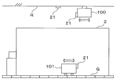
- FIG. 6 is a diagram for explaining another example of the mounting position of the antenna 21.
- the antenna 21 is attached to the housing 2a of the substrate processing apparatus 2.
- the mounting position of the antenna 21 is not limited to this example.
- the antenna 21 may be attached to the ceiling R of a clean room, for example.
- the antenna 21 may be attached to a moving body that moves in the clean room.
- the moving body is, for example, an OHT 100 that moves along a ceiling R or an AGV 101 that runs on a floor formed by a grating G in a clean room.
- the RFID tag 31 which is a passive wireless IC tag is used as a communication unit attached to each grating G to be monitored and performing communication for detecting the position of the grating G.
- the communication unit may be an active wireless IC tag that communicates using a wireless LAN, Bluetooth (registered trademark), ZigBee (registered trademark), or the like.
- a signal wave including the above-mentioned identification information is transmitted from the active wireless IC tag at regular intervals. Therefore, when the RFID tag 31 is used, it is unnecessary to radiate the modulated wave from the antenna 21, which is necessary to send the signal wave from the RFID tag 31.
- the position of the grating G is detected based on the intensity of the signal wave from the wireless IC tag attached to the grating G and the like.
- the method of detecting the position of the grating G is not limited to this method, and may be a method using an optical indoor GPS.
- an optical indoor GPS receiver is used as a communication unit that performs communication for detecting the position of the grating G.
- FIG. 7 is a plan view showing the outline of the overall configuration of the monitoring system 1 when the position of the grating G is detected using the optical indoor GPS.
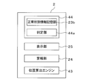
- FIG. 8 is a block diagram showing an outline of a configuration related to a monitoring process of the substrate processing apparatus 2 as a monitoring device when the position of the grating G is detected using the optical indoor GPS.
- a plurality of laser oscillators 41 for optical indoor GPS are used to monitor regions (grating G 601 to grating G 612 , grating G 701 to grating G 712 , It is provided so as to surround the grating G 801 to the grating G 812 .
- an optical sensor 42 as a receiver for an optical indoor GPS is attached to each of the gratings G to be monitored so that the light from the laser oscillator 41 can be received.
- Each laser oscillator 41 emits pulsed laser light at a predetermined timing, for example, under the control of the control unit 44 described later, and each optical sensor 42 A/D-converts the light reception result and outputs it.
- the substrate processing apparatus 2 as the monitoring apparatus of this example has a position calculation engine 43, a control unit 44, and the like.
- the position calculation engine 43 communicates with each optical sensor 42, and detects the position of each grating G by calculating the position of each optical sensor 42 based on the received light intensity at each optical sensor 42.
- the position calculation engine 43 and each optical sensor 42 are wirelessly connected.
- the position detection result of the position calculation engine 43 is used as the normal state information of the grating G, or used for the judgment by the judgment unit 44a described later.
- control unit 44 is a computer including, for example, a CPU and a memory. Further, the control unit 44 is mounted with the determination unit 44a and the like by the processing of the CPU according to the instruction of the program for realizing the monitoring processing.
- the alarm unit 24 and the display unit 25 output according to the determination result by the determination unit 44a.
- the normal state information is stored in the normal state information storage unit 23b of the control unit 23, and the determination unit 23c of the control unit 23 determines whether or not there is an opening.
- the reader/writer 22 is used to write and store the normal state information in each RFID tag 31, and the normal state information is acquired together with the identification information from each RFID tag 31 at the time of monitoring. May be performed by the reader/writer 22. As a result, the load on the control unit 23, which is the host controller, can be reduced.
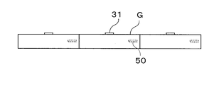
- FIG. 9 is a diagram for explaining the monitoring device according to the second embodiment, and shows the side surface of the grating G that constitutes the floor of the clean room.
- an active type wireless IC tag including an acceleration sensor and a gyro sensor as an operation detection unit is incorporated. 50 is attached.
- the active wireless IC tag 50 radiates a signal wave including a motion detection result for the grating G in the acceleration sensor and the gyro sensor at regular intervals, and the signal wave is received via the antenna of the monitoring device.
- the determination unit that is included in the monitoring device and determines whether or not there is an opening in the floor makes the above determination based on the following (A) to (C).
- the opening is present regardless of the result of motion detection of the grating G by the acceleration sensor and the gyro sensor. Further, when the motion for a part of the grating G is detected by the acceleration sensor and the gyro sensor, it is determined that the opening is present regardless of whether or not the position of the grating G matches the position in the normal state.
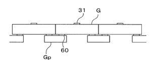
- FIG. 10 is a diagram illustrating another example of the motion detector.
- an active wireless IC tag 60 having a built-in weight sensor (pressure sensor) as an operation detection unit is attached to each mounting portion Gp of the grating G.
- FIG. 11 is a diagram for explaining the monitoring device according to the third embodiment.
- the substrate processing apparatus 2 also serves as the monitoring device.
- the portable terminal device M of the worker W functions as a monitoring device.
- the mobile terminal device M includes the antenna 21, the reader/writer 22, the control unit 23, the alarm unit 24, and the display unit 25 described with reference to FIG. Then, when it is determined that the opening is present based on the result received via the antenna 21 of the mobile terminal device M, for example, a warning is given by a sound from the alarm unit 24 or the position of the opening by the display unit 25 is indicated. The image is displayed.
- a vibrating vibrating unit may be provided in the mobile terminal device M, and when it is determined that the opening is present, the worker W may be warned by the vibration. Further, in the present embodiment, the functions related to the monitoring processing of the control unit 23, the alarm unit 24, and the display unit 25 may be provided in the substrate processing apparatus 2.
- the technology according to the present disclosure can be applied to a floor in a space other than a clean room, and can also be applied to a floor configured by floor members other than grating.
- a monitoring device for monitoring a floor configured by grating in a clean room Each grating is equipped with a communication unit that performs communication for detecting the position of the grating.
- the monitoring device is The presence or absence of the opening based on the detection result of the current position of the grating using the communication result with the communication unit and the information on the position of the grating in the normal state where the opening caused by the removal of the grating does not exist.
- the surveillance system according to (1) above can be constructed at low cost. Furthermore, the monitoring system according to (1) above can be constructed very easily and quickly.
- a motion detector that detects a motion for the grating is provided, The determination unit determines the presence or absence of the opening based on the detection result of the current grating position, information about the position of the grating in the normal state, and the detection result of the operation detecting unit.
- the monitoring device according to (1) above. According to the above (6), the safety can be further enhanced.
- the output unit is a display unit that displays at least one of an image indicating the presence of the opening and an image indicating the position of the opening when the opening is present,
- the monitoring device according to any one of (1) to (11).
- a monitoring method for monitoring a floor configured by grating in a clean room Each grating is equipped with a communication unit that performs communication for detecting the position of the grating.
- the monitoring method is A step of detecting the current position of the grating based on the communication result with the communication unit; Based on the result of the detection and the information about the position of the grating in a normal state in which the opening is not formed when the grating is removed, a step of determining the presence or absence of the opening, An output step of outputting according to the determination result of the presence or absence of the opening, the monitoring method.
- a substrate processing apparatus for processing a substrate comprising: The substrate processing apparatus is to be placed on a floor composed of grating in a clean room, Each grating is equipped with a communication unit that performs communication for detecting the position of the grating.
- the substrate processing apparatus is The presence or absence of the opening based on the detection result of the current position of the grating using the communication result with the communication unit and the information on the position of the grating in the normal state where the opening caused by the removal of the grating does not exist.
- a determination unit for determining comprising: an output unit that outputs according to a determination result of the presence or absence of the opening in the determination unit.
Landscapes
- Business, Economics & Management (AREA)
- Emergency Management (AREA)
- Physics & Mathematics (AREA)
- General Physics & Mathematics (AREA)
- Emergency Alarm Devices (AREA)
Abstract
L'invention concerne un dispositif de surveillance qui surveille un sol comprenant des grilles à l'intérieur d'une salle blanche. Des unités de communication sont fixées à chacune des grilles et réalisent des communications pour détecter les positions des grilles. Le dispositif de surveillance comprend : une unité de détermination qui, sur la base du résultat de la détection des positions actuelles des grilles à l'aide du résultat des communications avec les unités de communication et des informations concernant les positions des grilles dans un état normal lorsqu'il n'y a pas de parties d'ouverture présentes résultant du retrait des grilles, réalise une détermination de la présence des parties d'ouverture ; et une unité de sortie qui réalise une sortie en fonction du résultat de la détermination de la présence des parties d'ouverture par l'unité de détermination.
Priority Applications (1)
| Application Number | Priority Date | Filing Date | Title |
|---|---|---|---|
| JP2020559231A JP7105319B2 (ja) | 2018-12-13 | 2019-12-03 | 監視装置、監視方法及び基板処理装置 |
Applications Claiming Priority (2)
| Application Number | Priority Date | Filing Date | Title |
|---|---|---|---|
| JP2018233612 | 2018-12-13 | ||
| JP2018-233612 | 2018-12-13 |
Publications (1)
| Publication Number | Publication Date |
|---|---|
| WO2020121897A1 true WO2020121897A1 (fr) | 2020-06-18 |
Family
ID=71075304
Family Applications (1)
| Application Number | Title | Priority Date | Filing Date |
|---|---|---|---|
| PCT/JP2019/047258 Ceased WO2020121897A1 (fr) | 2018-12-13 | 2019-12-03 | Dispositif de surveillance, procédé de surveillance et dispositif de traitement de substrat |
Country Status (3)
| Country | Link |
|---|---|
| JP (1) | JP7105319B2 (fr) |
| TW (1) | TW202027044A (fr) |
| WO (1) | WO2020121897A1 (fr) |
Cited By (3)
| Publication number | Priority date | Publication date | Assignee | Title |
|---|---|---|---|---|
| WO2025110036A1 (fr) * | 2023-11-22 | 2025-05-30 | 東京エレクトロン株式会社 | Procédé de surveillance, dispositif de surveillance et support de stockage informatique |
| WO2025263371A1 (fr) * | 2024-06-21 | 2025-12-26 | 株式会社Screenホールディングス | Procédé d'aide au travail et système d'aide au travail |
| WO2025263227A1 (fr) * | 2024-06-21 | 2025-12-26 | 株式会社Screenホールディングス | Procédé d'aide au travail et système d'aide au travail |
Citations (2)
| Publication number | Priority date | Publication date | Assignee | Title |
|---|---|---|---|---|
| JP2014016799A (ja) * | 2012-07-09 | 2014-01-30 | Tokyo Electron Ltd | クリーンルームの監視装置及びクリーンルームの監視方法 |
| JP2017027306A (ja) * | 2015-07-21 | 2017-02-02 | 株式会社Iro | グレーチングおよび固定具 |
Family Cites Families (1)
| Publication number | Priority date | Publication date | Assignee | Title |
|---|---|---|---|---|
| JP7122187B2 (ja) * | 2018-07-26 | 2022-08-19 | 東京エレクトロン株式会社 | 基板処理装置周囲の監視システム |
-
2019
- 2019-12-03 TW TW108144077A patent/TW202027044A/zh unknown
- 2019-12-03 JP JP2020559231A patent/JP7105319B2/ja active Active
- 2019-12-03 WO PCT/JP2019/047258 patent/WO2020121897A1/fr not_active Ceased
Patent Citations (2)
| Publication number | Priority date | Publication date | Assignee | Title |
|---|---|---|---|---|
| JP2014016799A (ja) * | 2012-07-09 | 2014-01-30 | Tokyo Electron Ltd | クリーンルームの監視装置及びクリーンルームの監視方法 |
| JP2017027306A (ja) * | 2015-07-21 | 2017-02-02 | 株式会社Iro | グレーチングおよび固定具 |
Cited By (3)
| Publication number | Priority date | Publication date | Assignee | Title |
|---|---|---|---|---|
| WO2025110036A1 (fr) * | 2023-11-22 | 2025-05-30 | 東京エレクトロン株式会社 | Procédé de surveillance, dispositif de surveillance et support de stockage informatique |
| WO2025263371A1 (fr) * | 2024-06-21 | 2025-12-26 | 株式会社Screenホールディングス | Procédé d'aide au travail et système d'aide au travail |
| WO2025263227A1 (fr) * | 2024-06-21 | 2025-12-26 | 株式会社Screenホールディングス | Procédé d'aide au travail et système d'aide au travail |
Also Published As
| Publication number | Publication date |
|---|---|
| JP7105319B2 (ja) | 2022-07-22 |
| JPWO2020121897A1 (ja) | 2021-10-14 |
| TW202027044A (zh) | 2020-07-16 |
Similar Documents
| Publication | Publication Date | Title |
|---|---|---|
| US9269255B2 (en) | Worksite proximity warning | |
| AU2007317213B2 (en) | Protection, security and displacement-tracking luminous badge system | |
| CN102471040B (zh) | 升降装置高效装载物输送、装载监视、防撞以及装载避险 | |
| US9227820B2 (en) | Sensor unit system | |
| JP6501692B2 (ja) | 注意喚起情報提供システム | |
| JP7105319B2 (ja) | 監視装置、監視方法及び基板処理装置 | |
| KR101339928B1 (ko) | 위치기반의 통합형 무선 선박 관리 시스템 | |
| KR101774872B1 (ko) | 작업자 안전감시 시스템 | |
| JP2019131392A (ja) | 搬送装置、受信機能付き搬送装置、搬送システム、上位システム、搬送装置の制御方法、及びプログラム | |
| CN108137294A (zh) | 用于施工现场监控的方法,作业机器和用于施工现场监控的系统 | |
| TW201333842A (zh) | 具有實時增強實體板的資料中心基礎設施管理系統 | |
| KR101720857B1 (ko) | 안전 관제 시스템 | |
| KR20100050616A (ko) | 생체 신호 등을 기반으로 한 경계 근무 실시간 모니터링 시스템 | |
| KR20180011322A (ko) | 유압 회로의 밸브를 감시하기 위한 장비 및 방법, 연관된 유압 회로, 및 컴퓨터 프로그램 제품 | |
| KR20150083480A (ko) | 3차원 입체 영상을 활용한, 설비 통합 관리 시스템 | |
| JPWO2020100945A1 (ja) | 移動体 | |
| KR102439487B1 (ko) | 드론을 이용한 송전선로설비 상태점검 시스템 제공방법 | |
| JP2015005152A (ja) | クレーンの吊り荷と作業員の接近警告システム | |
| JP5961992B2 (ja) | 作業者管理システム | |
| JP2019209426A (ja) | ロボット状態監視システム及びロボット状態監視方法 | |
| KR101377706B1 (ko) | 위치기반의 무선 선박 관리 시스템 | |
| CN205943002U (zh) | 一种作业场所的rfid定位预警系统 | |
| KR102621097B1 (ko) | 물류센터 내에서의 위치 확인을 위한 gnss 연계 기반의 qr코드 생성장치 및 시스템 | |
| KR101744637B1 (ko) | 충돌 방지 장치 | |
| JP2007157032A (ja) | 監視システム |
Legal Events
| Date | Code | Title | Description |
|---|---|---|---|
| 121 | Ep: the epo has been informed by wipo that ep was designated in this application |
Ref document number: 19897401 Country of ref document: EP Kind code of ref document: A1 |
|
| ENP | Entry into the national phase |
Ref document number: 2020559231 Country of ref document: JP Kind code of ref document: A |
|
| NENP | Non-entry into the national phase |
Ref country code: DE |
|
| 122 | Ep: pct application non-entry in european phase |
Ref document number: 19897401 Country of ref document: EP Kind code of ref document: A1 |