WO2020122051A1 - Dispositif de pesage combiné - Google Patents
Dispositif de pesage combiné Download PDFInfo
- Publication number
- WO2020122051A1 WO2020122051A1 PCT/JP2019/048220 JP2019048220W WO2020122051A1 WO 2020122051 A1 WO2020122051 A1 WO 2020122051A1 JP 2019048220 W JP2019048220 W JP 2019048220W WO 2020122051 A1 WO2020122051 A1 WO 2020122051A1
- Authority
- WO
- WIPO (PCT)
- Prior art keywords
- article
- upstream
- feeder
- straight
- downstream
- Prior art date
- Legal status (The legal status is an assumption and is not a legal conclusion. Google has not performed a legal analysis and makes no representation as to the accuracy of the status listed.)
- Ceased
Links
Images


Classifications
-
- G—PHYSICS
- G01—MEASURING; TESTING
- G01G—WEIGHING
- G01G19/00—Weighing apparatus or methods adapted for special purposes not provided for in the preceding groups
- G01G19/387—Weighing apparatus or methods adapted for special purposes not provided for in the preceding groups for combinatorial weighing, i.e. selecting a combination of articles whose total weight or number is closest to a desired value
- G01G19/393—Weighing apparatus or methods adapted for special purposes not provided for in the preceding groups for combinatorial weighing, i.e. selecting a combination of articles whose total weight or number is closest to a desired value using two or more weighing units
-
- G—PHYSICS
- G01—MEASURING; TESTING
- G01G—WEIGHING
- G01G19/00—Weighing apparatus or methods adapted for special purposes not provided for in the preceding groups
- G01G19/387—Weighing apparatus or methods adapted for special purposes not provided for in the preceding groups for combinatorial weighing, i.e. selecting a combination of articles whose total weight or number is closest to a desired value
Definitions
- the present invention relates to a combination weighing device for combining and weighing various articles such as foods and confectionery in predetermined amounts, and particularly to a combination weighing device suitable for mixing and weighing small amounts of various kinds of articles.
- a weighing device suitable for mixing and weighing a plurality of types of articles for example, in Patent Document 1, a plurality of series of weighing units having a supply hopper and a weighing hopper in series in the vertical direction, and articles in each weighing unit are provided. There is disclosed a so-called horizontal arrangement combination weighing device in which supply units for supply are arranged in a line in a straight line.
- Patent Document 2 as a weighing device for mixing and weighing a plurality of types of articles, a weighing unit having a supply hopper and a weighing hopper is provided around a conical dispersion feeder that conveys the articles to be supplied to the outside.
- a so-called circular arrangement combination weighing device which is arranged along the circumferential direction is disclosed.
- the dispersion feeder when it is desired to increase the types of articles to be mixed and weighed, the dispersion feeder is made to have a large diameter, and a weighing hopper having a supply hopper and a weighing hopper arranged along the circumference thereof is provided. It is necessary to increase the number of units and expand the occupied space in all directions centering on the distributed feeder.
- the number of units of the weighing units arranged in a line and the supply unit may be linearly added.
- the circularly arranged combination scale there is an advantage that it can be configured compactly in a plane.
- the storage hopper of the supply unit supplies the article to the supply feeder, and the supply feeder conveys the article to the supply hopper of the measurement unit.
- the capacity of the storage hopper is increased to store a large amount of articles, depending on the type of the articles, the articles may be clogged near the supply port where the articles are supplied from the storage hopper to the supply feeder, or Items may become stagnant and jam in the hopper.
- a plurality of supply feeders are arranged in a stepwise manner from the upstream side to the downstream side in the conveying direction of the article, and the article is fed from the upstream side supply feeder located in the upper stage.
- it may be sequentially vibrated and conveyed to the downstream supply feeder located in the lower stage.
- the sensor detects that the article has been supplied from the end portion of the upstream supply feeder to the start portion of the downstream supply feeder, and performs control to stop the drive of the upstream supply feeder, The following problems may occur.
- the sensor detects the article at the start end of the downstream supply feeder, but as will be described later, when the article is, for example, an elongated article, from the end of the upstream supply feeder. However, a part of the article may jump out above the starting end of the downstream supply feeder. Then, the sensor detects a part of the popped-out article and stops the drive of the upstream side supply feeder on the assumption that the article is supplied from the upstream side supply feeder to the downstream side supply feeder. At this time, when the article in the balanced state in which a part of the upstream supply feeder protrudes above the starting end of the downstream supply feeder and remains in a balanced state, the sensor detects the article. It remains in the detection state. Therefore, although the article does not actually exist at the starting end of the downstream supply feeder, the upstream supply feeder supplies the article to the downstream supply feeder as if the article exists. The drive remains stopped as it is not necessary.
- the articles in a balanced state in which a part thereof jumps out from the end portion of the upstream supply feeder to above the start portion of the downstream supply feeder, and supplies the article in the balanced state from the upstream supply feeder to the downstream supply feeder.
- the product it may be erroneously detected that the product is a discharged product, and the driving of the supply feeder on the upstream side is stopped, which may interfere with the subsequent transportation of the product.
- the present invention has been made by paying attention to such a point, and it is an object of the present invention to make it possible to eliminate jamming of articles and obstruction of transportation of articles as much as possible.
- the present invention is configured as follows.
- a combination weighing device comprising: An upstream article detection means for detecting an article at an upstream end of the trough of the downstream rectilinear feeder in the transport direction is provided, and the control means controls the upstream rectilinear feeder when the article is not detected by the upstream article detection means.
- the upstream article detecting means drives the article until the article is detected, and when the predetermined time elapses after the driving of the upstream rectilinear feeder is started, the upstream rectilinear feeder is driven with increased vibration intensity.
- the upstream article detecting means for detecting the article at the upstream end of the trough of the downstream straight feeder, that is, when there is no article at the upstream end of the trough of the downstream straight feeder.
- the upstream linear feeder is driven until an article is detected by the upstream article detection means.
- the upstream linear feeder is Assuming that the articles are not supplied and the articles are jammed on the upstream side of the upstream rectilinear feeder, for example, in the vicinity of the supply port of the articles to the upstream rectilinear feeder, the driving is performed with the vibration intensity of the upstream rectilinear feeder increased.
- the strong vibration of the upstream linear feeder driven with this high vibration intensity makes it possible to break the clogging of the article and eliminate the clogging, and the operator does not have to manually eliminate the clogging of the article.
- a combination weighing device comprising: Upstream article detecting means for detecting an article at an upstream end of the trough of the downstream linear feeder in the carrying direction; and downstream article detecting means for detecting an article downstream in the carrying direction with respect to the upstream article detecting means.
- the control means when the article is not detected by the upstream article detection means, drives the upstream linear feeder until the article is detected by the upstream article detection means, and the control means,
- the downstream linear feeder is driven so as to convey the article to the downstream side
- the control means drives the upstream linear feeder until the article is detected by the upstream article detecting means, and the upstream
- the drive of the upstream straight advance feeder is started.
- the upstream straight feeder when the article is not detected by the upstream article detecting means for detecting the article at the upstream end of the trough of the downstream straight feeder, the upstream straight feeder is set to the upstream side of the trough of the downstream straight feeder by the upstream article detecting means. The drive is continued until the article at the side end is detected, and when the article is detected by the upstream article detecting means, the drive is stopped.
- the article when the article is, for example, an elongated article, a part of the article jumps out from the end portion of the upstream linear feeder to above the upstream end portion which is the starting end portion of the downstream linear feeder. , It may stand still in a balanced state.
- the upstream article detecting means jumps out from the terminal end portion of the upstream linear feeder to above the upstream end portion of the downstream linear feeder, and the article in a balanced state is supplied from the upstream linear feeder to the downstream linear feeder.
- an erroneous detection is made and the state where the drive of the upstream linear feeder is stopped is continued, which hinders the conveyance of the article.
- the upstream article detection means when the state where no article is detected by the downstream article detection means continues for a predetermined time after the driving of the upstream straight feeder is stopped, the upstream article detection means erroneously detects and conveys the article as described above. Assuming that there is a problem with the above, driving of the upstream straight feeder is started. As a result, a part of the article jumps above the upstream end of the downstream straight feeder from the terminal end of the upstream straight feeder, and the stationary article in a balanced state is supplied to the downstream straight feeder to Normal transport is resumed. Therefore, it is not necessary for the worker to feed the balanced articles that have jumped out from the end portion of the upstream linear feeder to the downstream linear feeder.
- a combination weighing device comprising: Upstream article detecting means for detecting an article at an upstream end of the trough of the downstream linear feeder in the carrying direction; and downstream article detecting means for detecting an article downstream in the carrying direction with respect to the upstream article detecting means.
- the control means drives the upstream linear feeder until the article is detected by the upstream article detection means, and drives the upstream linear feeder.
- the upstream straight advance feeder is driven so as to increase the vibration intensity, and the control means drives the downstream straight advance feeder to convey the article to the downstream side.
- the control means drives the upstream rectilinear feeder until the article is detected by the upstream article detecting means, and stops the driving of the upstream rectilinear feeder, and then the downstream article detecting means.
- the drive of the upstream linear feeder is started.
- the first predetermined time and the second predetermined time are preferably different, but may be the same.
- the upstream side of the upstream linear feeder for example, to the upstream linear feeder.
- driving is performed with the vibration strength of the upstream linear feeder increased.
- the strong vibration of the upstream linear feeder driven with this high vibration intensity makes it possible to break the clogging of the article and eliminate the clogging, and the operator does not have to manually eliminate the clogging of the article.
- the upstream article detection means when the state in which the article is not detected by the downstream article detection means continues for a second predetermined time after the driving of the upstream straight advance feeder is stopped, the upstream article detection means causes the upstream article detection means to terminate.
- the article in a balanced state that jumps out above the upstream end of the downstream straight-forward feeder is erroneously detected as the article being fed from the upstream straight-forward feeder to the downstream straight-forward feeder, and there is a problem in conveying the article.
- start driving the straight feeder As a result, the article jumping out from the end portion of the upstream linear feeder is supplied to the downstream linear feeder, and the normal conveyance of the article is restarted. Therefore, it is not necessary for the worker to feed the balanced articles that have jumped out from the end portion of the upstream linear feeder to the downstream linear feeder.
- a storage hopper that supplies the stored articles to the upstream end of the trough of the upstream linear feeder, and a storage hopper that is controlled by the control means and that travels straight upstream from the storage hopper.
- a notification means for notifying an abnormality in the supply of the article to the trough of the feeder the control means, by starting the drive in which the vibration intensity of the upstream rectilinear feeder is increased, by the upstream article detection means.
- the informing unit informs that the supply of the article is abnormal.
- the upstream side of the upstream straight feeder when the articles are not supplied to the upstream end of the trough of the downstream straight feeder even after a lapse of a predetermined time from the start of driving the upstream straight feeder, the upstream side of the upstream straight feeder, for example, to the upstream straight feeder.
- the driving is performed with the vibration strength of the upstream linear feeder increased.
- the notification means can notify that an abnormality has occurred in the supply of the article. Thereby, the operator who recognizes that the abnormality such as the clogging of the article occurs can take appropriate measures such as manually breaking the clogging of the article in order to eliminate the abnormality.
- an article sensor for detecting an article at a downstream end of a trough in the downstream straight feeder is provided, and the control means is configured to detect the article when the article sensor detects no article.
- the straight feeder is driven until an article is detected by the article sensor.
- the downstream straight feeder is driven until the article sensor detects the article. If the article is supplied from the straight advance feeder to the upstream end of the trough of the downstream straight feeder, the article is conveyed to the downstream end of the trough of the downstream straight feeder and can be detected by the article sensor.
- the downstream article detection means for detecting articles downstream of the upstream article detection means in the transport direction is downstream of the article sensor and the downstream linear feeder. It is at least one sensor of a weight sensor which weighs the weight of the article of the weighing hopper arranged on the side.
- an article sensor detects the article at the downstream end of the trough in the downstream straight feeder, or a weight sensor that weighs the weight of the article in the weighing hopper downstream of the downstream straight feeder. It is possible to detect whether or not it is supplied to the side.
- At least two straight advance feeders of the upstream straight advance feeder and the downstream straight advance feeder are set as a series, and a plurality of straight advance feeders are arranged in a line in a straight line.
- a plurality of units are arranged in a line in a straight line.
- a plurality of stations of the weighing units having a series of a supply hopper and a weighing hopper are arranged in a line in a straight line, and a plurality of straight feeders for supplying articles to the respective supply hoppers have a straight line. They are arranged in a line.
- the upstream straight feeder when there is no article at the upstream end of the trough of the downstream straight feeder, the upstream straight feeder is driven until the article is detected by the upstream article detecting means, and from the start of driving the upstream straight feeder. If no article is detected by the upstream article detection means even after a lapse of a predetermined time, the article is not supplied to the upstream rectilinear feeder, and the upstream side of the upstream rectilinear feeder, for example, the vicinity of the supply port of the article to the upstream rectilinear feeder. Assuming that the article is clogged with the like, the upstream straight feeder is driven by increasing the vibration intensity. Due to the strong vibration of the upstream linear feeder having high vibration strength, it is possible to break the clogging of the article and to smoothly supply the article to the upstream straight feeder, and the operator manually breaks the clogging of the article. No need.
- the upstream article detecting means for detecting the article at the upstream end of the trough of the downstream rectilinear feeder drives the upstream rectilinear feeder until the article is detected. Stop the drive of the feeder. At this time, a part of the article jumps out from the end of the upstream rectilinear feeder to the upper part of the downstream rectilinear feeder and stands still in a balanced state, and the upstream article detection means supplies the article from the upstream rectilinear feeder to the downstream rectilinear feeder. If it is falsely detected, the drive of the upstream straight feeder is started.
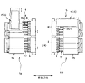
- FIG. 1 is a schematic side view of a combination weighing device according to an embodiment of the present invention.
- FIG. 2 is a schematic plan view of the combination weighing device of FIG.
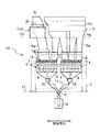
- FIG. 3 is a schematic front view of one of the weighing devices of FIG.
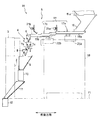
- FIG. 4 is a side view of a main part of the weighing device of FIG.
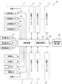
- FIG. 5 is a control block diagram of a main part of one weighing device 1A of FIG.
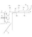
- FIG. 6 is a side view schematically showing a schematic configuration in the vicinity of the straight feeder and the weighing unit.
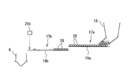
- FIG. 7A is a side view showing a part of FIG. 6 for explaining drive control of the straight feeder.
- FIG. 7B is a side view showing a part of FIG. 6 for explaining drive control of the straight feeder.
- FIG. 7A is a side view showing a part of FIG. 6 for explaining drive control of the straight feeder.
- FIG. 7B is a side view showing a part of FIG. 6 for explaining drive control of the
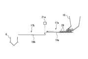
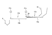
- FIG. 8A is a side view showing a part of FIG. 6 for explaining the abnormality in the supply of the articles in the straight feeder.
- FIG. 8B is a side view showing a part of FIG. 6 for explaining the abnormality in the supply of the articles in the straight feeder.
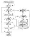
- FIG. 9 is a flowchart showing an example of control processing for the downstream straight feeder.
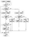
- FIG. 10 is a flowchart showing an example of control processing of the upstream straight feeder.
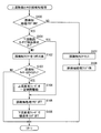
- FIG. 11 is a flowchart showing an example of the erroneous detection process of the upstream article sensor.
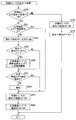
- FIG. 12 is a flowchart showing an example of a clogging process in the storage hopper.
- FIG. 13 is a side view schematically showing a schematic configuration in the vicinity of a linear feeder and a weighing unit according to another embodiment of the present invention.
- FIG. 1 is a side view of a combination weighing device according to an embodiment of the present invention
- FIG. 2 is a plan view thereof
- 3 is a schematic front view of one of the weighing devices of FIG. 1
- FIG. 4 is a schematic side view of a main part of one of the weighing devices of FIG.
- the combination weighing device of this embodiment is a device for combining and weighing various kinds of foods, confectionery, and the like, for example, eight kinds of articles in predetermined small amounts, and is, for example, nut, hail, bean confectionery, etc. It is suitable for a case where a snack set in which one or two small fish are mixed is mixed and weighed.
- This combination weighing device is installed on the first floor surface F1 and is used in a packaging line that puts the weighed articles into a packaging device (not shown) installed below the floor surface and packs them.
- the lateral direction in FIGS. 1, 2, and 4 and the front-back direction on the paper surface in FIG. 3 are referred to as the front-back direction.
- the front-back direction of the paper surface in FIGS. 1 and 4 and the lateral direction in FIG. 3 are referred to as the left-right direction.
- this combination weighing device has a structure in which a pair of weighing devices 1A and 1B are arranged face to face with a central passage R through which a worker can move left and right sandwiched.
- the weighing devices 1A and 1B are basically configured to have the same specifications, and the structure of the weighing devices 1A and 1B will be described below.
- each of the weighing devices 1A and 1B Inside of each of the weighing devices 1A and 1B (on the side of the central passage R), two bases 3 which are long in the left and right directions are installed at a predetermined height position via a support frame 2. On the outer side of the base body 3 (on the side opposite to the central passage R), a large number of weighing units 4 are installed in a line in the left and right.
- each weighing device 1A, 1B is equipped with 12 weighing units 4 in a row, and 24 weighing units 4 including both weighing devices 1A, 1B perform combined weighing of various kinds of articles. It has become.
- an article supply unit 5 for supplying various types of articles to be weighed to the upper portion of each weighing unit 4 is provided.
- the single weighing unit 4 is basically the same as the conventional one.
- the series of weighing units 4 stores the articles conveyed from the article supply section 5, and temporarily stores and discharges the articles, and a supply hopper 6 having an openable and closable gate, and the articles discharged from the supply hopper 6.
- the structure is arranged vertically in rows.
- the supply hopper 6, the weighing hopper 7, and the memory hopper 8 are detachably attached to the base body 3 in the same manner as in the conventional case.
- a gate drive mechanism for these hoppers 6, 7, and 8, a weight sensor for measuring the weight of the weighing hopper 6, and the like are housed in the base body 3.
- an outer gate 7a and an inner gate 7b that can be independently opened and closed are provided at the lower end of the weighing hopper 7.
- the weighed articles are discharged to the first collecting chute 9, and by swinging and opening only the inner gate 7b, the weighed articles are discharged to the memory hopper 8. It is designed to be temporarily stored.
- each weighing unit 4 is provided with the memory hopper 8
- the memory hopper 8 can also participate in the combination calculation in addition to the weighing hopper 7, and the number of hoppers (effective hoppers) that can participate in the combination calculation is increased. be able to.
- a plurality of weighing hoppers 7 selected by a combination calculation so that a predetermined weight is obtained, or a first set of four collecting the articles dropped from the memory hopper 8 and delivered.
- the chutes 9 are arranged in a line on the left and right.
- Two first collecting hoppers 10 that temporarily receive and store the articles collected by the first collecting chutes 9 are provided below the two first collecting chutes 9 that are adjacent to each other.
- a second collecting chute 11 that guides the articles dropped and discharged from each of the first collecting hoppers 10 by sliding down and collecting them.
- a second collecting hopper 12 for collecting and temporarily storing the articles weighed and collected using the twelve weighing units 4 is provided in each of the weighing devices 1A and 1B. One is arranged for each.
- a final collecting hopper 13 that collects the articles discharged from the second collecting hopper 12 provided in each of the weighing devices 1A and 1B, in one place.
- the final collecting hopper 13 installed is controlled to open and close based on a supply request command from the packaging device side.
- a metal detector 14 is provided in the guide path along which the articles flow from the second collecting hopper 12 to the final collecting hopper 13, and the mixture of metal foreign matters is finally monitored.
- the article supply unit 5 is provided with storage tanks 15 for storing articles and storage hoppers 16 connected to the lower ends of the storage tanks 15. Further, in the article supply section 5, twelve supply feeders 17 for vibrating and conveying the articles fed from the lower end of the storage hopper 16 toward the twelve stations of the weighing units 4 are arranged side by side on the upper side of the support table 18. Have been deployed.
- the storage tank 15 includes a lower-stage tank 15a that is dropped and supported in an opening of a second floor surface F2 that is installed further above the first floor surface F1, an intermediate-stage tank 15b that is removably positioned and connected to the lower tank 15a, and It is provided with an upper tank 15c.
- a storage tank 15 (C) having a different specification from the above is provided in order to supply articles that easily stick to each other such as small fish mirin and small light rice crackers. ..
- a belt conveyor 35 is used as shown in FIG. By rotating the belt conveyor 35, the articles stored in the upper tank 36 are conveyed, dropped, and sent out, and then sent to the storage hopper 16 through the lower tank 15a.
- the supply feeder 17 has two upstream straight feeders 17a and a downstream straight feeder 17b which are arranged in a row in a step-down manner. That is, the supply feeders 17 are arranged in a column so that the upstream linear feeder 17a is located in the upper stage and the downstream linear feeder 17b is located in the lower stage.
- Each of the linear feeders 17a and 17b includes trough-shaped troughs 19a and 19b having a groove-shaped cross-sectional shape, and vibrating mechanisms 20a and 20b installed above the support base 18.
- Articles fed from the storage hopper 16 to the upstream straight advance feeder 17a are vibrated and conveyed, transferred to the downstream straight advance feeder 17b, and sent little by little from the end of the downstream straight advance feeder 17b to the supply hopper 6 of the weighing unit 4.
- an upstream article sensor 21a and a downstream article sensor 21b that detect the stacking height of articles near the upstream start end and the downstream end of the lower linear feeder 17b, for example, with a laser are provided above the supply feeder 17, an upstream article sensor 21a and a downstream article sensor 21b that detect the stacking height of articles near the upstream start end and the downstream end of the lower linear feeder 17b, for example, with a laser are provided. Has been done. Based on the article detection information from the article sensors 21a and 21b, the drive of the linear feeders 17a and 17b is controlled as described later.
- FIG. 5 is a control block diagram of a main part of one weighing device 1A of the combination weighing device according to the present embodiment, and the other weighing device 1B basically has the same configuration. Representatively shown.
- the main configuration of the article supply unit 5 that supplies articles to the series of weighing units 4 is shown as a supply unit.
- a control device 25 that controls each unit is housed in the base body 3.
- the control device 25 is connected to an operation setting display device 26 that displays various settings such as operations on the weighing device 1A, operation parameters, and measurement values.
- the control device 25 is supplied with the detection outputs of the upstream article sensor 21a and the downstream article sensor 21b of the supply unit, and the weight signal from the weight sensor 22 that measures the weight of the weighing hopper 7.
- the control device 25 controls the driving of the upstream linear feeder 17a and the downstream linear feeder 17b of the supply unit, and also controls the opening and closing of the discharge gates of the hoppers 6, 7, 8, 10, 12, and 13.
- one weighing device 1A and the other weighing device 1B are connected by a LAN cable, and by operating the operation setting indicator 26, either weighing device 1A or 1B is the main weighing device. It can be set whether to use the device. For example, when the weighing device 1A is set as the main weighing device, the arithmetic control unit 27 of the control device 25 of the set weighing device 1A sets a total of 24 weighing hoppers 7 and memories of both weighing devices 1A and 1B. Based on the weight of the articles in the hopper 8, the combination calculation is performed so that the articles can be discharged from the hoppers 7 and 8 of the respective weighing devices 1A and 1B selected for the proper combination.
- FIG. 6 is a side view schematically showing a schematic configuration in the vicinity of the linear feeders 17a and 17b and the weighing unit 4.
- the laser-type upstream article sensor 21a for detecting articles supplied to the trough 19b is provided above the starting end portion of the downstream linear feeder 17b on the upstream side of the trough 19b. Further, a laser-type downstream article sensor 21b for detecting articles at the end section of the trough 19b is provided above the end section on the downstream side of the trough 19b of the downstream linear feeder 17b.
- the articles in the storage hopper 16 are discharged to the trough 19a of the upstream rectilinear feeder 17a and vibrated and conveyed downstream in the conveying direction as the upstream rectilinear feeder 17a vibrates, and from the end of the trough 19a of the upstream rectilinear feeder 17a. It is carried out and supplied to the starting end of the trough 19b of the downstream linear feeder 17b. Further, the articles supplied to the starting end of the trough 19b of the downstream straight feeder 17b are conveyed to the end of the trough 19b of the downstream straight feeder 17b, and when there is an instruction to convey the articles to the supply hopper 6, the supply hopper It is discharged to 6. Further, the articles supplied to the supply hopper 6 are supplied to the weighing hopper 7, weighed by the weight sensor 22, and then discharged from the weighing hopper 7 to the memory hopper 8 or the first collecting chute 9.
- the downstream linear feeder 17b detects that the downstream article sensor 21b does not detect the article 28 at the downstream end, which is the terminal end of the trough 19b of the downstream linear feeder 17b, that is, the downstream of the trough 19b.
- the article 28 is driven by the downstream article sensor 17b until the article 28 is detected, and the article 28 is conveyed to the downstream end of the trough 19b.
- downstream linear feeder 17b supplies the article 28 at the downstream end of the trough 19b, that is, when the article 28 is present at the downstream end of the trough 19b, by the downstream article sensor 21b.
- the downstream linear feeder 17b supplies the article 28 at the downstream end of the trough 19b, that is, when the article 28 is present at the downstream end of the trough 19b, by the downstream article sensor 21b.
- the upstream straight advance feeder 17a detects when the upstream article sensor 21a does not detect the article 28 at the upstream end, which is the starting end of the trough 19b of the downstream straight advance feeder 17b, that is, the downstream straight advance.
- the article 28 of the trough 19a of the upstream linear feeder 17a is driven by the upstream article sensor 21a until the article 28 is detected. Carry out to trough 19b.
- the upstream linear feeder 17a is stopped when the article 28 is supplied to the trough 19b of the downstream linear feeder 17b and the upstream article sensor 21a detects the article 28 at the upstream end of the trough 19b. ..
- the articles in the storage hopper 16 are sequentially conveyed from the upstream side to the downstream side by the both linear feeders 17a and 17b and are supplied to the supply hopper 6 of the weighing unit 4.
- the supply may not be performed normally.
- a slender article 28 such as a small fish
- the upstream linear feeder 17a is driven until the upstream article sensor 21a detects the article at the upstream end of the trough 19b of the downstream linear feeder 17b, and the upstream article sensor 21a detects the article. Then, the driving is stopped. Therefore, due to the erroneous detection by the upstream article sensor 21a, the drive of the upstream linear feeder 17a may remain stopped, and the article may not be supplied to the downstream linear feeder 7b.
- the upstream article sensor 21a may erroneously detect that a part of the article 28 that has jumped out has been supplied to the upstream end of the trough 19b, and the drive of the upstream linear feeder 17a may be stopped.
- the article 28 When the drive of the upstream linear feeder 17a is stopped, the article 28 is restrained by the succeeding article 28 and stands still in balance with a part of the article 28 protruding from the discharge end of the trough 19a of the upstream linear feeder 17a. Sometimes. Then, although the article 28 is not yet supplied to the upstream end of the trough 19b of the downstream linear feeder 7b, the upstream article sensor 21a incorrectly detects the article 28 that has jumped out from the downstream end of the trough 19a. The state continues. For this reason, the driving of the upstream linear feeder 17a remains stopped, and the supply of articles to the downstream linear feeder 17a is interrupted.
- the upstream article sensor 21a In order to prevent the upstream article sensor 21a from erroneously detecting the article 28 jumping out from the discharge end of the trough 19b of the upstream linear feeder 17b, it is conceivable to arrange the upstream article sensor 21a so as to be shifted downstream in the article conveyance direction. .. However, the upstream linear feeder 17a is started to be driven when the article is no longer detected by the upstream article sensor 21a. Therefore, when the upstream article sensor 21a is arranged so as to be shifted to the downstream side, the drive of the upstream rectilinear feeder 17a for supplying the article to the downstream rectilinear feeder 17b is performed by the upstream article detection sensor arranged to be shifted to the downstream side. Will not start until is no longer detected.
- the start timing of the drive of the upstream linear feeder 17a is delayed, the articles cannot be continuously supplied, and an interval occurs between the conveyed articles.
- a state in which there is no article at the downstream end of the downstream linear feeder 17b occurs the article cannot be supplied from the downstream linear feeder 17b to the supply hopper 6, and therefore the article cannot be supplied from the supply hopper 6 to the weighing hopper 7.
- a cycle occurs. For this reason, the number of hoppers that can participate in the combination calculation is reduced, the combination accuracy is reduced, or the combination is not established, and the production amount is reduced.
- the upstream article sensor 21a is arranged close to the upstream end of the trough 19b of the downstream straight feeder 17b so that the article supplied to the upstream end of the trough 19b of the downstream straight feeder 17b can be immediately detected. Is preferred.
- the upstream linear feeder 17a is configured such that when the upstream article sensor 21a does not detect an article at the upstream end of the trough 19b of the downstream linear feeder 17b, that is, the upstream end of the trough 19b of the downstream linear feeder 17b. When there is no article in the article, the article is driven by the upstream article sensor 21a until the article is detected.
- the upstream article sensor 21a continues to detect the article at the upstream end of the trough 19b of the downstream rectilinear feeder 17b even after the preset predetermined time has elapsed since the driving of the upstream rectilinear feeder 17a was started. In this case, for example, it is determined that the article has not been supplied to the upstream rectilinear feeder 17a because the article is stagnant near the supply port of the storage hopper 16 or in the storage hopper 16 and jams. In this case, the vibration intensity of the upstream linear feeder 17a is increased to a preset vibration intensity and driving is continued.
- the vibration intensity can be set in stages by operating the operation setting display 26, and how many stages the vibration intensity should be increased is preset according to the property of the article.
- the drive in which the vibration intensity of the upstream linear feeder 17a is increased is such that the article is cleared of clogging, the article is conveyed by the upstream linear feeder 17a, and is discharged to the upstream end of the trough 19b of the downstream linear feeder 17b.
- the processed article is continued until it is detected by the upstream article sensor 21a.
- the drive in which the vibration intensity of the upstream linear feeder 17a is increased is continued for a preset time. Further, even if a preset predetermined time elapses from the start of the drive in which the vibration intensity of the upstream linear feeder 17a is increased, the upstream article sensor 21a detects the articles on the upstream side end portion of the trough 19b of the downstream linear feeder 17b.
- the notification is not limited to the display by the operation setting display 26, and may be, for example, a notification by sound, a notification by a display lamp, or a combination thereof.
- the upstream article sensor 21a detects an article that has jumped out of the discharge end of the trough 19a of the upstream linear feeder 17a, it is determined that the article has been supplied to the upstream end of the trough 19b of the downstream linear feeder 17b. The driving of the linear feeder 17a is stopped.
- the downstream article sensor 21b does not detect the article at the downstream end of the trough 19b of the downstream rectilinear feeder 17b after the driving of the upstream rectilinear feeder 17 is stopped, when the upstream article sensor 21a continues for a predetermined time. However, even if the article is detected, it is determined to be a false detection. In this case, the driving of the upstream linear feeder 17a is started and is driven for a preset time.
- the preset time may be a time period in which the articles at the discharge end of the trough 19a of the upstream linear feeder 17a can be discharged to the trough 19b of the downstream linear feeder 17b.
- the balanced articles in a state of jumping out from the discharge end of the trough 19a of the upstream linear feeder 17a are dropped and discharged to the upstream end of the trough 19b of the downstream linear feeder 17b.
- the articles supplied to the upstream end of the trough 19b of the downstream linear feeder 17b are conveyed to the downstream end of the trough 19b of the downstream linear feeder 17b.
- the upstream rectilinear feeder 17a is started to drive when it continues for a preset time.
- a weight sensor 22 that detects the weight of the weighing hopper 7 to which the article is fed via the downstream linear feeder 17b and the supply hopper 6 is used to detect the empty state in which the article is not fed.
- the driving of the upstream linear feeder 17a may be started when the preset time has continued.
- FIG. 9 is a flowchart showing an example of a control process of the downstream straight advance feeder 17b
- FIG. 10 is a flowchart showing an example of a control process of the upstream straight advance feeder 17a. Both are programs executed at regular time intervals, for example, every 10 msec.
- step S1 when the operation switch is turned on (step S1), whether or not the “supplying hopper in-supply flag” indicating that the article is being supplied to the supply hopper 6 is turned on. It is determined (step S2). In step S2, when the "supplying hopper supply flag" is ON, the article is being supplied, so the count value of the supply timer that measures the supply time is decremented by 1 (step S3), It is determined whether or not the supply timer has timed out (step S4).
- step S4 when the supply timer has timed out, it is determined that the supply of the article to the supply hopper 6 is completed, and the "supply hopper supply flag" is turned off (step S5), and the driving of the downstream linear feeder 17b is stopped ( It turns off and moves to step S7 (step S6).
- step S7 it is determined whether the operation switch has been turned off. If the operation switch has not been turned off, the process returns to step S2 (step S7).
- step S2 when the "supplying hopper in-supply flag" is not turned on, it is determined whether or not an article is detected by the downstream article sensor 21b (step S8). When an article is detected in step S8, it is determined whether or not there is an instruction to convey the article to the supply hopper 6 (step S9). When there is no instruction to convey the article to the supply hopper 6, the procedure proceeds to step S6. ..
- step S9 when there is an instruction to convey the article to the supply hopper 6, since the article is supplied to the supply hopper 6, the "supplying hopper in-supply flag" is turned on and the process proceeds to step S11 (step S10).
- step S11 the supply timer is set, the driving of the downstream straight feeder 17b is started (ON) (step S12), and the process proceeds to step S7.
- step S8 when the downstream article sensor 21b does not detect the article, the process proceeds to step S12 to start driving the downstream rectilinear feeder 17b in order to convey the article to the downstream end of the trough 19b of the downstream rectilinear feeder 17b. To do.
- step S20 when the operation is turned on (step S20), it is determined whether or not the upstream article sensor 21a has detected an article (step S21).
- step S21 the drive of the upstream straight advance feeder 17a is stopped (OFF) (step S22), and the article is being conveyed by the downstream straight advance feeder 17b. It is determined whether or not is ON (step S23). In step S23, if the "downstream straight feeding feeder conveying flag" is not ON, the process proceeds to step S24.
- step S24 it is determined whether or not the downstream article sensor 21b has detected the article.
- the "downstream rectilinear feeder 17 conveying flag" indicating that the article is being conveyed by the downstream rectilinear feeder 17b. Is turned on (step S25) and the operation switch is not turned off, the process returns to step S21 (step S26).
- step S23 when the "transporting flag in the downstream straight feeder 17b" is ON, the process proceeds to the erroneous detection process of the upstream article sensor 21a (step S27), and the process proceeds to step S26.
- step S21 When the article is not detected by the upstream article sensor 21a in step S21, driving of the upstream rectilinear feeder 17a is started (ON) to supply the article to the upstream end of the trough 19b of the downstream rectilinear feeder 17b (step S28). ), and proceeds to step S29.
- step S29 it is determined whether or not the "upstream straight-forward feeder transporting flag" indicating that the article is being transported by the upstream straight-forward feeder 17a is ON.
- step S29 when the "upstream straight-forward feeder conveying flag" is not turned on, the "upstream straight-forward feeder conveying flag” is turned on, and the process proceeds to step S26 (step S30).
- step S29 when the "upstream straight feeding feeder conveying flag" is ON, the process proceeds to the clogging process in the storage hopper 16 (S step 31), and the process proceeds to step S26.
- FIG. 11 is a flowchart showing an example of an erroneous detection process (step S27) of the upstream article sensor 21a in FIG.
- step S100 it is determined whether the erroneous detection process flag is ON (step S100), and when it is not ON, the erroneous detection timer is set (step S107), the erroneous detection process flag is turned ON, and the process returns (step S108). ).
- step S100 when the erroneous detection processing flag is ON, it is determined whether or not the downstream article sensor 21b has detected an article (step S101). When no article is detected in step S101, the count value of the false detection timer is decremented by 1 (step S102), and it is determined whether or not the false detection timer has timed up (step S103). If the time is not up in step S103, the process returns. If the time is up, the process proceeds to step S104.
- step S104 it is determined that the upstream article sensor 21a has erroneous detection, and the upstream straight advance feeder 17a is driven for a certain period of time, and the article that is balanced in a state of jumping out from the discharge end of the trough 19a of the upstream straight advance feeder 17a is moved straight downstream. It is supplied to the upstream end of the trough 19b of the feeder 17b, and the process proceeds to step S105.
- step S105 the erroneous detection processing flag is turned off, the "transporting flag in downstream downstream feeder” is turned off, and the process returns (step S106).
- step S101 when an article is detected by the downstream article sensor 21b, the process proceeds to step S105.
- FIG. 12 is a flowchart showing an example of the clogging process (step S31) in the storage hopper 16 in FIG.
- step S200 it is determined whether or not the "clogging process flag in the storage hopper" is ON (step S200), and when the "clogging process flag in the storage hopper" is not ON, the "clogging process flag in the storage hopper” is determined. Is turned on (step S209), the clogging detection timer is set (step S210), and the process returns.
- step S200 when the "clogging processing flag in the storage hopper" is turned on, it is determined whether or not an article is detected by the upstream article sensor 21a (step S201). When no article is detected in step S201, the count value of the jam detection timer is decremented by 1 (step S202), and it is determined whether or not the jam detection timer has timed out (step S203). When the time is up in step S203, it is determined that the storage hopper 16 side is clogged with articles, and the vibration intensity of the upstream linear feeder 17a is increased to drive for a certain period of time (step S204), and the process proceeds to step S205.
- step S205 it is determined whether or not an article is detected by the upstream article sensor 21a. When no article is detected, it is determined that clogging of the article cannot be eliminated even by driving the upstream rectilinear feeder 17a with increased vibration intensity. It is notified that an abnormality has occurred in the supply of articles (step S206), and the process proceeds to step S207. When an article is detected in step S205, the process proceeds to step S207.
- step S207 the "clogging processing flag in the storage hopper” is turned off, the “transporting flag in upstream upstream feeder” is turned off, and the process returns (step S208).
- step S205 when an article is detected by the upstream article sensor 21a, the process proceeds to step S207.
- the vibration strength of the upstream straight advance feeder 17a is increased.
- the strong vibration of the upstream linear feeder 17a having a high vibration intensity it becomes possible to break the clogging of the article and smoothly supply the article to the upstream linear feeder 17a. This eliminates the need for the operator to manually break the jam of the article.
- the upstream article sensor 21a moves an article that is stationary in a balanced state in which a part of the article jumps out above the downstream rectilinear feeder 17b from the terminal end portion of the upstream rectilinear feeder 17a to the downstream rectilinear feeder 17a.
- the driving of the upstream linear feeder 17a is started.
- the balanced articles are supplied to the downstream straight-travel feeder and normal conveyance of the articles is resumed, so that the worker jumps out of the end portion of the upstream straight-travel feeder and balances the articles to the downstream straight-travel feeder. Need not be supplied to.
- two straight feeders are provided, but three or more straight feeders may be provided.
- three first to third linear feeders 17 1 to 17 3 are provided from the upstream side to the downstream side.
- the first article sensor 21 1 for detecting articles at the upstream end of the trough 19 2 of the second straight advance feeder 17 2 and the upstream and downstream ends of the trough 19 3 of the third straight advance feeder 17 3.
- Second and third article sensors 21 2 and 21 3 for detecting articles of the respective parts are provided.
- the first linear feeder 17 1 is the upstream linear feeder
- the second linear feeder 17 2 is the downstream linear feeder
- the first article sensor 21 1 is the upstream article sensor
- the storage hopper is the same as in the above embodiment. The clogging of the article at 16 is cleared.
- the first linear feeder 17 1 is an upstream linear feeder
- the second linear feeder 17 2 is a downstream linear feeder
- the first article sensor 21 1 is an upstream article sensor
- the second article sensor 21 2 is a downstream article sensor.
- the articles which are balanced in a state of protruding from the discharge end of the trough 19 1 of the first linear feeder 17 1 are supplied to the trough 19 2 of the second linear feeder 17 2 .
- the second linear feeder 17 2 is an upstream linear feeder
- the third linear feeder 17 3 is a downstream linear feeder
- the second article sensor 21 2 is an upstream article sensor
- the third article sensor 21 2 is a downstream article sensor.
- the balanced articles in the state of jumping out from the discharge end of the trough 19 2 of the second straight advance feeder 17 2 are supplied to the trough 19 3 of the third straight advance feeder 17 3 17 1 may be the upstream straight feeder and the third straight feeder 17 3 may be the downstream straight feeder.
- each weighing unit is equipped with a memory hopper to increase the number of valid hoppers that can participate in the combination calculation, but the memory hopper may be omitted.
Landscapes
- Physics & Mathematics (AREA)
- General Physics & Mathematics (AREA)
- Feeding Of Articles To Conveyors (AREA)
Abstract
Dans la présente invention, lorsqu'un article n'est pas présent dans la section terminale côté amont de l'auge d'un dispositif d'alimentation à avance rectiligne en aval, un dispositif d'alimentation à avance rectiligne en amont est activé jusqu'à ce qu'un article soit détecté par un capteur d'article en amont, et lorsqu'un article n'est pas détecté par le capteur d'article en amont même après qu'un temps prédéterminé se soit écoulé depuis le début de l'activation du dispositif d'alimentation à avance rectiligne en amont, il est supposé que l'article est bloqué en amont du dispositif d'alimentation à avance rectiligne en amont, et le dispositif d'alimentation à avance rectiligne en amont est activé avec une intensité de vibration accrue.
Priority Applications (3)
| Application Number | Priority Date | Filing Date | Title |
|---|---|---|---|
| US17/286,081 US11898897B2 (en) | 2018-12-14 | 2019-12-10 | Combination weighing device |
| EP19894981.0A EP3885719B1 (fr) | 2018-12-14 | 2019-12-10 | Dispositif de pesage combiné |
| CN201980070769.1A CN112997052B (zh) | 2018-12-14 | 2019-12-10 | 组合计量装置 |
Applications Claiming Priority (2)
| Application Number | Priority Date | Filing Date | Title |
|---|---|---|---|
| JP2018-233976 | 2018-12-14 | ||
| JP2018233976A JP7130335B2 (ja) | 2018-12-14 | 2018-12-14 | 組合せ計量装置 |
Publications (1)
| Publication Number | Publication Date |
|---|---|
| WO2020122051A1 true WO2020122051A1 (fr) | 2020-06-18 |
Family
ID=71077289
Family Applications (1)
| Application Number | Title | Priority Date | Filing Date |
|---|---|---|---|
| PCT/JP2019/048220 Ceased WO2020122051A1 (fr) | 2018-12-14 | 2019-12-10 | Dispositif de pesage combiné |
Country Status (5)
| Country | Link |
|---|---|
| US (1) | US11898897B2 (fr) |
| EP (1) | EP3885719B1 (fr) |
| JP (1) | JP7130335B2 (fr) |
| CN (1) | CN112997052B (fr) |
| WO (1) | WO2020122051A1 (fr) |
Cited By (1)
| Publication number | Priority date | Publication date | Assignee | Title |
|---|---|---|---|---|
| US20220289494A1 (en) * | 2021-03-12 | 2022-09-15 | Ishida Co., Ltd. | Article conveyance device and combination weighing device |
Families Citing this family (4)
| Publication number | Priority date | Publication date | Assignee | Title |
|---|---|---|---|---|
| JP7220952B2 (ja) * | 2018-12-14 | 2023-02-13 | 大和製衡株式会社 | 組合せ計量装置 |
| JP7114189B2 (ja) * | 2018-12-19 | 2022-08-08 | 大和製衡株式会社 | 組合せ計量装置 |
| US12263971B2 (en) * | 2023-02-23 | 2025-04-01 | Coastal Counting & Industrial Scale Company, Inc. | System and method for a product packaging assembly |
| JP2024131246A (ja) | 2023-03-15 | 2024-09-30 | 株式会社イシダ | 搬送装置 |
Citations (6)
| Publication number | Priority date | Publication date | Assignee | Title |
|---|---|---|---|---|
| JPH05330632A (ja) * | 1992-05-28 | 1993-12-14 | Yamato Scale Co Ltd | 物品供給装置 |
| WO2004042335A1 (fr) * | 2002-11-05 | 2004-05-21 | Cetech V/Claus Engelbrecht | Appareil de pesage automatique combine |
| JP2012237576A (ja) | 2011-05-10 | 2012-12-06 | Yamato Scale Co Ltd | 混合計量用組合せ秤 |
| JP2016148557A (ja) * | 2015-02-10 | 2016-08-18 | 株式会社イシダ | 組合せ計量装置 |
| JP2018077074A (ja) | 2016-11-08 | 2018-05-17 | 大和製衡株式会社 | 計量装置 |
| JP2018184260A (ja) * | 2017-04-26 | 2018-11-22 | 大和製衡株式会社 | 物品供給装置及びそれを備えた計量システム |
Family Cites Families (14)
| Publication number | Priority date | Publication date | Assignee | Title |
|---|---|---|---|---|
| JP3195089B2 (ja) * | 1992-05-22 | 2001-08-06 | 大和製衡株式会社 | 多段階重量選別機 |
| WO1995031702A1 (fr) * | 1994-05-13 | 1995-11-23 | Ishida Co., Ltd. | Appareil pour peser une combinaison d'objets |
| JP3756637B2 (ja) * | 1997-09-04 | 2006-03-15 | 株式会社イシダ | 組合せ計量装置とこれを備えた物品の充填装置 |
| JP5808957B2 (ja) * | 2011-06-15 | 2015-11-10 | 大和製衡株式会社 | 組合せ秤 |
| JP5785123B2 (ja) * | 2012-03-16 | 2015-09-24 | 株式会社イシダ | 組合せ計量装置 |
| DK3098580T3 (da) * | 2014-01-20 | 2020-04-20 | Ishida Seisakusho | Kombinationsvægtindretning |
| JP3198972U (ja) * | 2015-05-20 | 2015-07-30 | 株式会社イシダ | 搬送装置とそれを使用した組合せ計量装置 |
| JP6759060B2 (ja) * | 2016-11-08 | 2020-09-23 | 大和製衡株式会社 | 計量装置 |
| JP2018112429A (ja) * | 2017-01-10 | 2018-07-19 | 株式会社イシダ | 組合せ計量装置 |
| JP6935120B2 (ja) * | 2017-01-27 | 2021-09-15 | 大和製衡株式会社 | 物品供給装置及びそれを備えた計量システム |
| JP6858628B2 (ja) * | 2017-04-26 | 2021-04-14 | 大和製衡株式会社 | 物品振分け装置及びそれを備えた物品供給装置 |
| WO2019239498A1 (fr) * | 2018-06-12 | 2019-12-19 | 大和製衡株式会社 | Dispositif d'amenée d'articles |
| JP7220952B2 (ja) * | 2018-12-14 | 2023-02-13 | 大和製衡株式会社 | 組合せ計量装置 |
| GB201912242D0 (en) * | 2019-08-27 | 2019-10-09 | Ishida Europe Ltd | Slack seperation apparatus and method |
-
2018
- 2018-12-14 JP JP2018233976A patent/JP7130335B2/ja active Active
-
2019
- 2019-12-10 CN CN201980070769.1A patent/CN112997052B/zh active Active
- 2019-12-10 US US17/286,081 patent/US11898897B2/en active Active
- 2019-12-10 EP EP19894981.0A patent/EP3885719B1/fr active Active
- 2019-12-10 WO PCT/JP2019/048220 patent/WO2020122051A1/fr not_active Ceased
Patent Citations (6)
| Publication number | Priority date | Publication date | Assignee | Title |
|---|---|---|---|---|
| JPH05330632A (ja) * | 1992-05-28 | 1993-12-14 | Yamato Scale Co Ltd | 物品供給装置 |
| WO2004042335A1 (fr) * | 2002-11-05 | 2004-05-21 | Cetech V/Claus Engelbrecht | Appareil de pesage automatique combine |
| JP2012237576A (ja) | 2011-05-10 | 2012-12-06 | Yamato Scale Co Ltd | 混合計量用組合せ秤 |
| JP2016148557A (ja) * | 2015-02-10 | 2016-08-18 | 株式会社イシダ | 組合せ計量装置 |
| JP2018077074A (ja) | 2016-11-08 | 2018-05-17 | 大和製衡株式会社 | 計量装置 |
| JP2018184260A (ja) * | 2017-04-26 | 2018-11-22 | 大和製衡株式会社 | 物品供給装置及びそれを備えた計量システム |
Non-Patent Citations (1)
| Title |
|---|
| See also references of EP3885719A4 |
Cited By (2)
| Publication number | Priority date | Publication date | Assignee | Title |
|---|---|---|---|---|
| US20220289494A1 (en) * | 2021-03-12 | 2022-09-15 | Ishida Co., Ltd. | Article conveyance device and combination weighing device |
| US11866268B2 (en) * | 2021-03-12 | 2024-01-09 | Ishida Co., Ltd. | Article conveyance device and combination weighing device |
Also Published As
| Publication number | Publication date |
|---|---|
| JP7130335B2 (ja) | 2022-09-05 |
| CN112997052B (zh) | 2023-01-24 |
| EP3885719A1 (fr) | 2021-09-29 |
| JP2020094946A (ja) | 2020-06-18 |
| CN112997052A (zh) | 2021-06-18 |
| US20210381878A1 (en) | 2021-12-09 |
| EP3885719B1 (fr) | 2023-06-14 |
| US11898897B2 (en) | 2024-02-13 |
| EP3885719A4 (fr) | 2022-01-05 |
Similar Documents
| Publication | Publication Date | Title |
|---|---|---|
| WO2020122051A1 (fr) | Dispositif de pesage combiné | |
| US8525049B2 (en) | Combination weigher having reduced batch time and improved operational speed | |
| EP3617671B1 (fr) | Dispositif de pesage par combinaison | |
| WO2018139127A1 (fr) | Dispositif d'alimentation vibrant et dispositif d'alimentation d'article l'utilisant | |
| JP6935120B2 (ja) | 物品供給装置及びそれを備えた計量システム | |
| WO2020122052A1 (fr) | Dispositif de pesage combinatoire | |
| JP7009070B2 (ja) | 物品規制装置及びそれを備えた物品供給装置 | |
| JP6858628B2 (ja) | 物品振分け装置及びそれを備えた物品供給装置 | |
| JP2018184260A (ja) | 物品供給装置及びそれを備えた計量システム | |
| JP7023591B2 (ja) | 物品供給装置 | |
| JP6556010B2 (ja) | 計量装置 | |
| JP6925735B2 (ja) | 物品供給装置 | |
| JP2020132411A (ja) | 直進フィーダ用のトラフ及びこれを備えた組合せ秤 | |
| JP5825972B2 (ja) | 組合せ秤 | |
| JP5984634B2 (ja) | 組合せ秤 | |
| WO2023105571A1 (fr) | Dispositif de pesée par combinaison |
Legal Events
| Date | Code | Title | Description |
|---|---|---|---|
| 121 | Ep: the epo has been informed by wipo that ep was designated in this application |
Ref document number: 19894981 Country of ref document: EP Kind code of ref document: A1 |
|
| NENP | Non-entry into the national phase |
Ref country code: DE |
|
| ENP | Entry into the national phase |
Ref document number: 2019894981 Country of ref document: EP Effective date: 20210625 |