WO2020122099A1 - Dispositif de commande et procédé de détermination de défaillance - Google Patents
Dispositif de commande et procédé de détermination de défaillance Download PDFInfo
- Publication number
- WO2020122099A1 WO2020122099A1 PCT/JP2019/048397 JP2019048397W WO2020122099A1 WO 2020122099 A1 WO2020122099 A1 WO 2020122099A1 JP 2019048397 W JP2019048397 W JP 2019048397W WO 2020122099 A1 WO2020122099 A1 WO 2020122099A1
- Authority
- WO
- WIPO (PCT)
- Prior art keywords
- switching circuit
- voltage
- failure
- semiconductor switches
- control unit
- Prior art date
- Legal status (The legal status is an assumption and is not a legal conclusion. Google has not performed a legal analysis and makes no representation as to the accuracy of the status listed.)
- Ceased
Links
Images


Classifications
-
- H—ELECTRICITY
- H02—GENERATION; CONVERSION OR DISTRIBUTION OF ELECTRIC POWER
- H02H—EMERGENCY PROTECTIVE CIRCUIT ARRANGEMENTS
- H02H7/00—Emergency protective circuit arrangements specially adapted for specific types of electric machines or apparatus or for sectionalised protection of cable or line systems, and effecting automatic switching in the event of an undesired change from normal working conditions
- H02H7/20—Emergency protective circuit arrangements specially adapted for specific types of electric machines or apparatus or for sectionalised protection of cable or line systems, and effecting automatic switching in the event of an undesired change from normal working conditions for electronic equipment
-
- H—ELECTRICITY
- H02—GENERATION; CONVERSION OR DISTRIBUTION OF ELECTRIC POWER
- H02H—EMERGENCY PROTECTIVE CIRCUIT ARRANGEMENTS
- H02H7/00—Emergency protective circuit arrangements specially adapted for specific types of electric machines or apparatus or for sectionalised protection of cable or line systems, and effecting automatic switching in the event of an undesired change from normal working conditions
- H02H7/08—Emergency protective circuit arrangements specially adapted for specific types of electric machines or apparatus or for sectionalised protection of cable or line systems, and effecting automatic switching in the event of an undesired change from normal working conditions for dynamo-electric motors
- H02H7/0833—Emergency protective circuit arrangements specially adapted for specific types of electric machines or apparatus or for sectionalised protection of cable or line systems, and effecting automatic switching in the event of an undesired change from normal working conditions for dynamo-electric motors for electric motors with control arrangements
- H02H7/0844—Fail safe control, e.g. by comparing control signal and controlled current, isolating motor on commutation error
-
- F—MECHANICAL ENGINEERING; LIGHTING; HEATING; WEAPONS; BLASTING
- F02—COMBUSTION ENGINES; HOT-GAS OR COMBUSTION-PRODUCT ENGINE PLANTS
- F02N—STARTING OF COMBUSTION ENGINES; STARTING AIDS FOR SUCH ENGINES, NOT OTHERWISE PROVIDED FOR
- F02N11/00—Starting of engines by means of electric motors
- F02N11/08—Circuits specially adapted for starting of engines
-
- H—ELECTRICITY
- H02—GENERATION; CONVERSION OR DISTRIBUTION OF ELECTRIC POWER
- H02H—EMERGENCY PROTECTIVE CIRCUIT ARRANGEMENTS
- H02H1/00—Details of emergency protective circuit arrangements
- H02H1/0007—Details of emergency protective circuit arrangements concerning the detecting means
-
- H—ELECTRICITY
- H03—ELECTRONIC CIRCUITRY
- H03K—PULSE TECHNIQUE
- H03K17/00—Electronic switching or gating, i.e. not by contact-making and –breaking
-
- H—ELECTRICITY
- H03—ELECTRONIC CIRCUITRY
- H03K—PULSE TECHNIQUE
- H03K17/00—Electronic switching or gating, i.e. not by contact-making and –breaking
- H03K17/51—Electronic switching or gating, i.e. not by contact-making and –breaking characterised by the components used
- H03K17/56—Electronic switching or gating, i.e. not by contact-making and –breaking characterised by the components used by the use, as active elements, of semiconductor devices
- H03K17/687—Electronic switching or gating, i.e. not by contact-making and –breaking characterised by the components used by the use, as active elements, of semiconductor devices the devices being field-effect transistors
-
- B—PERFORMING OPERATIONS; TRANSPORTING
- B60—VEHICLES IN GENERAL
- B60R—VEHICLES, VEHICLE FITTINGS, OR VEHICLE PARTS, NOT OTHERWISE PROVIDED FOR
- B60R16/00—Electric or fluid circuits specially adapted for vehicles and not otherwise provided for; Arrangement of elements of electric or fluid circuits specially adapted for vehicles and not otherwise provided for
- B60R16/02—Electric or fluid circuits specially adapted for vehicles and not otherwise provided for; Arrangement of elements of electric or fluid circuits specially adapted for vehicles and not otherwise provided for electric constitutive elements
Definitions
- the present disclosure relates to a control device and a failure determination method.
- This application claims the priority based on Japanese application No. 2018-231892 filed on December 11, 2018, and incorporates all the contents described in the Japanese application.
- Patent Document 1 discloses a vehicle control device in which a failure diagnosis unit is provided in each semiconductor switch in a switching circuit in which a plurality of semiconductor switches are arranged in parallel to control a large current supplied to a load. ..
- the failure diagnosis unit diagnoses whether or not there is a malfunction in the semiconductor switch by determining the consistency between the ON/OFF control signal input to the semiconductor switch and the output level of the semiconductor switch.
- a control device includes a switching circuit, and a starter having a capacitor connected to one end of the switching circuit by controlling on/off of the switching circuit, and a starter having the other end of the switching circuit.
- a control device for a vehicle that opens and closes between an on-vehicle battery and a voltage detection unit that detects a voltage at the one end, and controls the switching circuit from on to off, thereby switching the switching circuit from on to off.
- a control unit that determines whether or not there is a failure in the switching circuit based on the voltage detected by the voltage detection unit when a predetermined time has elapsed after the control.
- a failure determination method includes a switching circuit, and a starter having a capacitor connected to one end of the switching circuit by controlling ON/OFF of the switching circuit, and a starter having the other end of the switching circuit.
- FIG. 1 is a circuit block diagram illustrating a configuration example of a vehicle current control system according to a first embodiment. It is a block diagram which shows the structural example of a control apparatus.
- 3 is a timing chart showing a failure determination method according to the first embodiment. It is explanatory drawing which shows the diagnostic method of a short circuit failure. It is a timing chart which shows the diagnostic method of a short circuit failure. It is explanatory drawing which shows the diagnosing method of an open failure.
- 6 is a timing chart showing a method of diagnosing an open failure. 6 is a flowchart showing a processing procedure of the failure determination method according to the first embodiment.
- 7 is a timing chart showing a method of diagnosing a short circuit failure according to the second embodiment.
- 9 is a timing chart showing a method of diagnosing an open failure according to the second embodiment.
- 9 is a flowchart showing a processing procedure of a failure determination method according to the second embodiment.
- 9 is a flowchart showing a processing procedure of a failure determination method according to the second embodiment.
- 9 is a flowchart showing a processing procedure of a failure determination method according to the third embodiment.
- An object of the present disclosure is to provide a control device capable of promptly determining the presence/absence of a failure in a switching circuit when a capacitor is connected to a circuit to be controlled to be switched, without waiting for the capacitor to be completely discharged. And to provide a failure determination method.
- a control device includes a switching circuit, a starter having a capacitor connected to one end of the switching circuit by controlling ON/OFF of the switching circuit, and the other end of the switching circuit.
- a control device for a vehicle that opens and closes between a vehicle-mounted battery that is connected to, a voltage detection unit that detects a voltage at the one end, and a switching circuit that controls the switching circuit from on to off, thereby turning on the switching circuit.
- a control unit that determines whether or not there is a failure in the switching circuit based on the voltage detected by the voltage detection unit when a predetermined time has elapsed after the control from OFF to OFF.
- the control unit can determine whether or not there is a failure in the switching circuit in a short time. For example, by setting the predetermined time to a time shorter than the time required to complete the discharge of the capacitor charged by the vehicle-mounted battery, the control unit completely discharges the capacitor charged by the vehicle-mounted battery. Therefore, it is possible to determine whether or not there is a failure in the switching circuit in a time shorter than the time required for this.
- the control unit controls the switching circuit from on to off. When the switching circuit is on, the capacitor and the vehicle-mounted battery are connected and the capacitor is in a charged state.
- the control unit determines whether or not there is a failure in the switching circuit based on the voltage at the one end of the switching circuit when a predetermined time has elapsed after controlling the switching circuit from ON to OFF. judge.
- the predetermined time is shorter than the time required to completely discharge the capacitor charged by the vehicle-mounted battery.
- the threshold value is, for example, the voltage of the capacitor when a predetermined time has elapsed after the switching circuit was controlled from ON to OFF, and is a numerical value for determining whether the switching circuit normally turned from ON to OFF. Therefore, the control unit can determine whether or not there is a failure in the switching circuit before a predetermined time elapses, that is, before the discharge of the capacitor is completed.
- the switching circuit has a plurality of semiconductor switches connected in parallel, and the control unit opens and closes the starter and the vehicle-mounted battery by simultaneously turning on and off the plurality of semiconductor switches.
- the control unit controls all or part of the plurality of semiconductor switches from on to off while the switching circuit is on, and turns all or part of the plurality of semiconductor switches from on to off. It is preferable that the presence/absence of a failure of the plurality of semiconductor switches is determined based on the voltage detected by the voltage detection unit when the predetermined time has elapsed after the control.
- the switching circuit has a plurality of semiconductor switches connected in parallel. Therefore, the control device can open and close a circuit through which a large current that cannot be controlled by one semiconductor switch flows.
- the control unit can determine whether or not there is a failure in the plurality of semiconductor switches.
- the control unit controls the plurality of semiconductor switches to be off while the switching circuit is on, and controls the plurality of semiconductor switches to be off when the predetermined time has elapsed.
- the voltage detected by the detection unit is larger than a predetermined threshold value, it is preferable to determine that the semiconductor switch is short-circuited and has a short circuit failure.
- the control unit controls the voltage detected by the voltage detection unit when the switching circuit is on and the semiconductor switches to be off when the switching circuit is on.
- a short-circuit failure in which the semiconductor switch is short-circuited A configuration that determines that there is is preferable.
- the control unit controls one of the semiconductor switches to be turned on and another of the plurality of semiconductor switches to be turned off, and the control unit controls the one semiconductor switch to be turned on when the predetermined time has elapsed.
- the voltage detected by the voltage detection unit is less than a predetermined threshold value, it is preferable to determine that the semiconductor switch is an open failure in which the one semiconductor switch is not turned on.
- the control unit controls the voltage detected by the voltage detection unit when the switching circuit is on, one semiconductor switch to be turned on, and a plurality of other semiconductor switches to be turned off.
- the difference from the voltage detected by the voltage detection unit when the predetermined time has elapsed after controlling one semiconductor switch to be turned on is equal to or higher than a predetermined threshold voltage, the one semiconductor switch is turned on.
- a configuration in which it is determined that the open failure does not occur is preferable.
- control unit determines the open failure of each of the plurality of semiconductor switches by selectively turning on each of the plurality of semiconductor switches.
- control unit sets the length of the predetermined time based on the voltage detected by the voltage detection unit when the switching circuit is in the ON state.
- control unit sets the length of the predetermined time to be shorter as the voltage detected by the voltage detection unit is higher when the switching circuit is in the ON state.
- the failure determination method includes a starter having a switching circuit, the starter having a capacitor connected to one end of the switching circuit by controlling ON/OFF of the switching circuit, and the other end of the switching circuit.
- a failure determination method for determining a failure of a vehicle control device that opens and closes a vehicle-mounted battery connected to a vehicle part comprising: controlling the switching circuit from ON to OFF; and turning the switching circuit from ON to OFF. The step of detecting the voltage of the one end when a predetermined time has elapsed after the control is performed, and the step of determining the presence or absence of a failure of the switching circuit based on the detected voltage.
- the control unit controls the voltage detected by the voltage detection unit in a state where the switching circuit is on, and all or a part of the plurality of semiconductor switches from on to off for the predetermined time. It is preferable that the presence/absence of a failure of the plurality of semiconductor switches be determined by comparing a difference between the voltage detected by the voltage detection unit and the predetermined threshold voltage when is passed.
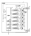
- FIG. 1 is a circuit block diagram illustrating a configuration example of a vehicle current control system according to the first embodiment.
- the vehicle current control system according to the first embodiment includes a vehicle control device 1, a starter generator 2, an in-vehicle battery 3, and a load 4.
- the control device 1 includes a control unit 10, a switching circuit 11, a drive unit 12, and a voltage detection unit 13.
- the first terminal 1a is connected to one end of the switching circuit 11, and the second terminal 1b is connected to the other end of the switching circuit 11.
- the first terminal 1a is connected to one end of the starter generator 2 and the other end of the starter generator 2 is grounded.
- the starter generator 2 has a power generating function in addition to a starter function for starting the vehicle engine, and includes a motor 21 for starting the engine and a capacitor 22.
- One end of the capacitor 22 is connected to the first terminal 1a, and the other end of the capacitor 22 is grounded.
- the positive terminal of the vehicle-mounted battery 3 is connected to the second terminal 1b, and the negative electrode of the vehicle-mounted battery 3 is grounded.
- one end of the load 4 is connected to the second terminal 1b, and the other end of the load 4 is grounded.
- the load 4 is an in-vehicle device such as an interior light, an air conditioner, a car navigation device, or the like.
- the starter generator 2 is connected to the vehicle-mounted battery 3 and the load 4 via the control device 1.
- the control device 1 opens and closes between the starter generator 2 and the vehicle-mounted battery 3.
- the starter generator 2 including the capacitor 22 and the vehicle battery 3 are connected.
- the vehicle-mounted battery 3 and the capacitor 22 are charged by the power generation of the starter generator 2.
- the capacitor 22 is charged by the on-vehicle battery 3 when the capacitor 22 and the on-vehicle battery 3 are connected.
- the control device 1 opens the circuit and disconnects the starter generator 2 and the vehicle-mounted battery 3.
- the motor 21 When the engine is started in this state, the motor 21 is driven by the starter battery (not shown) connected to the starter generator 2, and the engine is started. Although a large amount of electric power is required to drive the motor 21, the starter generator 2 and the vehicle-mounted battery 3 and the load 4 are disconnected, so it is possible to avoid problems such as a drop in the voltage on the load 4 side.
- the control device 1 closes the circuit, and the starter generator 2 and the vehicle-mounted battery 3 are connected.
- FIG. 2 is a block diagram showing a configuration example of the control device 1.
- the switching circuit 11 has first to sixth semiconductor switches 11a, 11b, 11c, 11d, 11e, 11f connected in parallel. .., 11f are preferably MOSFETs (Metal-Oxide-Semiconductor Field-Effect Transistors), IGBTs (Insulated Gate Bipolar Transistors), and the like.
- MOSFETs Metal-Oxide-Semiconductor Field-Effect Transistors
- IGBTs Insulated Gate Bipolar Transistors
- description will be made assuming that the first to sixth semiconductor switches 11a,..., 11f are N-channel MOSFETs.
- the drains of the first to sixth semiconductor switches 11a,..., 11f are connected to the second terminal 1b, and the sources are connected to the first terminal 1a.
- the switching circuit 11 in which six semiconductor switches are connected in parallel is described, but the number of semiconductor switches is not particularly limited to six.
- the driving unit 12 includes first to sixth driving circuits 12a, 12b, 12c, 12d, 12e, and 12f for turning on/off the first to sixth semiconductor switches 11a,..., 11f, the operation of which is controlled by the control unit 10. Controlled.
- the output terminals of the first to sixth drive circuits 12a,..., 12f are connected to the gates of the first to sixth semiconductor switches 11a,..., 11f, and the first to sixth drive circuits 12a,. By applying the drive voltage to the gate, the first to sixth semiconductor switches 11a,..., 11f are turned on and off.
- the first drive circuit 12a includes, for example, a first transistor and a second transistor connected in series, and the gate of the first semiconductor switch 11a is connected to the connection point of the first transistor and the second transistor.
- the control unit 10 is a computer having a CPU, a storage unit 10a, a clock unit 10b, an input/output unit 10c, and the like, which are not shown.
- the storage unit 10a stores information for determining whether or not there is a failure in the first to sixth semiconductor switches 11a,..., 11f. Details of the information will be described later.
- the storage unit 10a also stores the failure diagnosis results of the first to sixth semiconductor switches 11a,..., 11f.
- the input/output unit 10c externally outputs a signal or data indicating a failure of the first to sixth semiconductor switches 11a,..., 11f or the presence/absence of a failure.
- the voltage detection unit 13 includes a transistor switch 13a and voltage dividing resistors 13b and 13c connected in series.
- the control unit 10 can detect the voltage of the first terminal 1a, that is, the first terminal 1a of the switching circuit 11, by turning on the transistor switch 13a and acquiring the divided voltage.
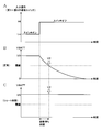
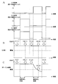
- FIG. 3 is a timing chart showing the failure determination method according to the first embodiment.
- the horizontal axis represents time.
- the vertical axis in FIG. 3A indicates the on/off state of the first to sixth semiconductor switches 11a,..., 11f, and the vertical axis in FIG. 3B indicates the voltage VBATT of the first terminal 1a detected by the voltage detection unit 13. ing.
- the voltage V0 indicates a predetermined voltage of the vehicle-mounted battery 3.
- the predetermined voltage is a rated voltage, which is a constant that does not change depending on the state of the vehicle-mounted battery 3.
- the voltage of the first terminal 1a is the predetermined voltage V0 of the vehicle-mounted battery 3 and the voltage of the capacitor 22 is also the voltage V0.
- the capacitor 22 is discharged (see the white arrow in FIG. 1), and the voltage VBATT at the first terminal 1a exponentially decreases. ..
- the predetermined time is shorter than the time required to complete the discharge of the capacitor 22 charged by the vehicle-mounted battery 3.
- the threshold voltage is the difference between the voltage V0 and the voltage VBATT of the first terminal 1a detected when the fully charged capacitor 22 starts discharging and a predetermined diagnosis waiting time (predetermined time) elapses.
- a value obtained by subtracting the threshold voltage from the voltage V0 is called a threshold.
- the storage unit 10a of the control unit 10 stores the threshold voltage and the diagnostic waiting time.
- FIG. 4 is an explanatory diagram showing a method of diagnosing a short circuit failure
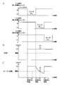
- FIG. 5 is a timing chart showing a method of diagnosing a short circuit failure.
- the horizontal axis represents time.
- the vertical axis in FIG. 5A represents the voltage level of the input signal output from the control unit 10 to the first to sixth drive circuits 12a,..., 12f
- the vertical axis in FIGS. 5B and 5C represents the first terminal 1a.
- the voltage VBATT is shown.
- 5B shows changes in the voltage VBATT when the first to sixth semiconductor switches 11a,..., 11f are normal
- FIG. 5C shows a short-circuit failure in any of the first to sixth semiconductor switches 11a,.
- the change in the voltage VBATT during the operation is shown.
- the control unit 10 controls all the first to sixth semiconductor switches 11a,..., 11f from on to off.
- the switching circuit 11 is turned off. Therefore, the capacitor 22 and the vehicle-mounted battery 3 are disconnected, the capacitor 22 is discharged, and the voltage of the capacitor 22 decreases as shown in FIG. 5B.
- control unit 10 uses the voltage V2 of the first terminal 1a when a predetermined diagnostic waiting time has elapsed after controlling the first to sixth semiconductor switches 11a,..., 11f from ON to OFF, It is possible to determine whether or not there is a short circuit failure in the first to sixth semiconductor switches 11a,..., 11f.
- FIG. 6 is an explanatory diagram showing a method of diagnosing an open fault
- FIG. 7 is a timing chart showing a method of diagnosing an open fault.
- the vertical axis in FIG. 7A represents the voltage level of the input signal output from the control unit 10 to the first to third drive circuits 12c
- the vertical axis in FIGS. 7B and 7C represents the voltage VBATT of the first terminal 1a.
- 7B shows a change in the voltage VBATT when the first to third semiconductor switches 11a, 11b, 11c are normal
- FIG. 7C shows a change in the voltage VBATT when the second semiconductor switch 11b has an open failure. Shows.
- the control unit 10 controls any one of the first to sixth semiconductor switches 11a,..., 11f to be turned on. For example, as shown in FIG. 7A, only the first semiconductor switch 11a is controlled to be turned on. The other second to sixth semiconductor switches 11b, 11c, 11d, 11e and 11f are off.
- the first semiconductor switch 11a is normally turned on, the capacitor 22 and the vehicle-mounted battery 3 are connected and the capacitor 22 is charged. The charging of the capacitor 22 is completed in a short time, and the battery of the capacitor 22 becomes the voltage of the vehicle-mounted battery 3. Therefore, as shown in FIG. 7B, the voltage of the first terminal 1a becomes the voltage V0.
- the second semiconductor switch 11b is controlled to be turned on.
- the switching circuit 11 does not turn on. Therefore, the capacitor 22 and the vehicle-mounted battery 3 are disconnected, the capacitor 22 is discharged, and the voltage of the capacitor 22 decreases as shown in FIG. 7C.
- the control unit 10 uses the voltage V2 of the first terminal 1a at the time when a predetermined diagnostic waiting time has elapsed after controlling the second semiconductor switch 11b to be turned on, and short-circuits the second semiconductor switch 11b. The presence or absence of can be determined. Similarly, the control unit 10 uses the voltage V2 of the first terminal 1a when a predetermined diagnostic waiting time has elapsed after controlling one of the first to sixth semiconductor switches 11a,..., 11f to be turned on. , 1 to 6 semiconductor switches 11a,...
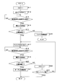
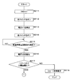
- FIG. 8 is a flowchart showing the processing procedure of the failure determination method according to the first embodiment.
- the control unit 10 substitutes 1 into the variable IND (step S11).
- the variable IND indicates one of the first to sixth semiconductor switches 11a,..., 11f by a numerical value.
- control unit 10 controls the first to sixth semiconductor switches 11a,..., 11f from on to off (step S12).
- the control unit 10 determines whether or not the elapsed time after controlling the first to sixth semiconductor switches 11a,..., 11f from on to off is equal to or longer than a predetermined diagnostic waiting time (step S13). When it is determined that the elapsed time is not longer than the diagnosis waiting time (step S13: NO), the control unit 10 returns the process to step S13 and continues the diagnosis process.
- the control unit 10 causes the voltage detection unit 13 to detect the voltage V2 (step S14).
- the voltage V2 indicates the voltage VBATT of the first terminal 1a detected when the elapsed time for waiting for diagnosis has elapsed as shown in FIG.
- the control unit 10 determines whether the absolute value of the difference between the voltage V0 of the vehicle-mounted battery 3 and the voltage V2 detected in step S14 is equal to or higher than the threshold voltage (step S15). When it is determined that the absolute value is less than the threshold voltage (step S15: NO), the control unit 10 definitely diagnoses that the first to sixth semiconductor switches 11a,..., 11f have a short circuit failure (step S16). ), processing is completed. When it is determined that the absolute value is equal to or higher than the threshold voltage (step S15: YES), the control unit 10 controls one of the first to sixth semiconductor switches 11a,..., 11f indicated by the variable IND from off to on.
- Step S17 it is determined whether or not the elapsed time after the ON control is longer than or equal to a predetermined diagnostic waiting time (step S18).
- a predetermined diagnostic waiting time step S18: NO
- the control unit 10 returns the process to step S18 and continues the diagnosis process.
- step S18 When it is determined that the elapsed time is equal to or longer than the diagnostic waiting time (step S18: YES), the control unit 10 causes the voltage detection unit 13 to detect the voltage V2 (step S19).
- control unit 10 determines whether the absolute value of the difference between the voltage V0 of the vehicle-mounted battery 3 and the voltage V2 detected in step S19 is equal to or higher than the threshold voltage (step S20). When it is determined that the absolute value is equal to or higher than the threshold voltage (step S20: YES), the control unit 10 determines that one of the first to sixth semiconductor switches 11a,..., 11f indicated by the variable IND has an open failure. Diagnosis is made (step S21), and the process ends.
- step S20 When it is determined in step S20 that the absolute value is less than the threshold voltage (step S20: NO), the control unit 10 increments the variable IND by 1 (step S22). Then, the control unit 10 determines whether or not the variable IND is larger than the number of the first to sixth semiconductor switches 11a,..., 11f (step S23). When it is determined that the variable IND is equal to or less than the number of switches (step S23: NO), the control unit 10 returns the process to step S17 and diagnoses the open failure of the other first to sixth semiconductor switches 11a,..., 11f. continue. When it is determined that the variable IND is larger than the number of switches (step S23: YES), the control unit 10 ends the process.
- the control unit 10 may store the failure determination result shown in FIG. 8 in the storage unit 10a. Further, the control unit 10 may be configured to externally output the failure determination result via the input/output unit 10c. Further, in the first embodiment, an example in which the absolute value of the difference between the voltage V0 of the vehicle-mounted battery 3 and the voltage V2 detected in step S14 or step S19 is greater than or equal to the threshold voltage has been described. It may be configured to determine whether or not the voltage V2 detected in step S14 is less than or equal to the threshold value (see FIG. 3).
- the control unit 10 that executes the process of step S15 causes a short-circuit failure in the first to sixth semiconductor switches 11a,..., 11f. If it is determined that the voltage V2 is equal to or lower than a predetermined threshold value, it is possible to determine that the first to sixth semiconductor switches 11a,..., 11f are not short-circuited.
- the control unit 10 that executes the process of step S20 opens one of the first to sixth semiconductor switches 11a,..., 11f indicated by the variable IND.
- the voltage V2 is higher than the threshold value, it may be determined that one of the first to sixth semiconductor switches 11a,..., 11f indicated by the variable IND does not have an open failure. ..
- the control device 1 and the failure determination method according to the first embodiment configured as described above when the capacitor 22 is connected to the circuit to be controlled to be switched, it is not necessary to wait until the capacitor 22 is completely discharged. Also, it is possible to quickly determine whether or not the switching circuit 11 has a failure.
- the switching circuit 11 can open and close a circuit through which a large current that cannot be controlled by one semiconductor switch flows. it can.
- FIG. 9 is a timing chart showing a method of diagnosing a short circuit failure according to the second embodiment.
- 9A to 9C are views similar to FIGS. 5A to 5C.
- the control unit 10 When determining the presence or absence of a short circuit failure, the control unit 10 first detects the voltage V1 of the first terminal 1a. That is, the current voltage of the vehicle-mounted battery 3 is detected.
- the control device 1 according to the second embodiment determines whether or not there is a failure in the switching circuit 11 by using not the rated voltage V0 of the vehicle-mounted battery 3 but the current voltage V1 of the vehicle-mounted battery 3.
- the control unit 10 controls all the first to sixth semiconductor switches 11a,..., 11f from on to off.
- the capacitor 22 and the vehicle-mounted battery 3 are disconnected, the capacitor 22 is discharged, and the voltage of the capacitor 22 is changed as shown in FIG. 9B. That is, the voltage VBATT at the first terminal 1a decreases.
- the voltage of the capacitor 22 that is, the voltage VBATT of the first terminal 1a does not decrease as shown in FIG. 9C.
- the control unit 10 controls the voltage V1 of the first terminal 1a before switching control, and controls the first to sixth semiconductor switches 11a,..., 11f from ON to OFF when a predetermined diagnostic waiting time elapses. Whether or not there is a short circuit failure in the first to sixth semiconductor switches 11a,..., 11f can be determined using the magnitude of the difference from the voltage V2 at the 1-terminal 1a.
- FIG. 10 is a timing chart showing a method of diagnosing an open failure according to the second embodiment.
- 10A, 10B, and 10C are views similar to FIG. 7.
- the presence or absence of the open failure is determined in the same manner as in the first embodiment, but the voltage V1 of the first terminal 1a immediately before turning on the first to sixth semiconductor switches 11a,..., 11f is detected. The points are different.
- the control unit 10 Immediately before turning on each of the first to sixth semiconductor switches 11a,..., 11f one by one, the control unit 10 temporarily sets all the first to sixth semiconductor switches 11a,..., 11f as shown in FIG. 10A. Is turned on (the input signal is at the low level Lo), and the voltage V1 of the first terminal 1a is detected.
- the control unit 10 controls the voltage V1 of the first terminal 1a before the switching control and one of the first to sixth semiconductor switches 11a,... Whether or not there is an open failure in each of the first to sixth semiconductor switches 11a,..., 11f can be determined using the magnitude of the difference from the voltage V2 at the first terminal 1a.
- 11 and 12 are flowcharts showing the processing procedure of the failure determination method according to the second embodiment.
- the control unit 10 substitutes 1 into the variable IND (step S211). Then, the controller 10 turns on the first to sixth semiconductor switches 11a,..., 11f (step S212), and causes the voltage detector 13 to detect the voltage V1 of the first terminal 1a (step S213). Next, the control unit 10 detects the voltage of the first terminal 1a after the elapse of a predetermined diagnostic waiting time by executing the same processing as Steps S12 to 14 of the first embodiment in Steps S214 to S216.
- the control unit 10 determines whether the absolute value of the difference between the voltage V1 detected in step S213 and the voltage V2 detected in step S216 is equal to or more than the threshold voltage (step S217). When it is determined that the absolute value is less than the threshold voltage (step S217: NO), the control unit 10 definitely diagnoses that the first to sixth semiconductor switches 11a,..., 11f have a short circuit failure (step S218). ), processing is completed. When it is determined that the absolute value is equal to or higher than the threshold voltage (step S217: YES), the control unit 10 turns on the first to sixth semiconductor switches 11a,..., 11f (step S219), and causes the voltage detection unit 13 to operate. The voltage V1 of the first terminal 1a is detected (step S220).
- control unit 10 controls the switches other than one of the first to sixth semiconductor switches 11a,..., 11f indicated by the variable IND to be turned off, and the elapsed time after performing the switching control waits for a predetermined diagnosis. It is determined whether it is time or more (step S222). When it is determined that the elapsed time is not longer than the diagnosis waiting time (step S222: NO), the control unit 10 returns the process to step S222 and continues the diagnosis process.
- control unit 10 When it is determined that the elapsed time is equal to or longer than the diagnostic waiting time (step S222: YES), the control unit 10 causes the voltage detection unit 13 to detect the voltage V2 (step S223).
- the control unit 10 determines whether the absolute value of the difference between the voltage V1 detected in step S220 and the voltage V2 detected in step S223 is equal to or more than the threshold voltage (step S224).
- step S224 YES
- processing is completed.
- the processing of steps S226 and S227 when the absolute value is less than the threshold voltage is the same as the processing of steps S22 and S23 of the first embodiment.
- control device 1 and the failure determination method according to the second embodiment configured as described above have the same effects as those of the first embodiment, and further, the failure of the switching circuit 11 can be detected without depending on the voltage level of the vehicle-mounted battery 3. The presence or absence can be determined.
- FIG. 13 is a flowchart showing the processing procedure of the failure determination method according to the third embodiment.
- the control unit 10 substitutes 1 into the variable IND (step S310). Then, the controller 10 turns on the first to sixth semiconductor switches 11a,..., 11f (step S311), and causes the voltage detector 13 to detect the voltage V1 of the first terminal 1a (step S312). Next, the control unit 10 determines the diagnostic waiting time based on the detected voltage V1 (step S313). For example, the control unit 10 determines the threshold voltage so that the diagnosis waiting time becomes shorter as the voltage V1 is higher. Then, the control unit 10 controls the first to sixth semiconductor switches 11a,..., 11f from on to off (step S314). The subsequent processing is the same as steps S13 to S23 of the first embodiment.
- the presence or absence of the failure of the switching circuit 11 can be determined more quickly by using the diagnostic waiting time according to the voltage level of the vehicle-mounted battery 3. can do.
- the threshold voltage may be changed based on the voltage V1 detected in step S312, or both the threshold voltage and the diagnosis waiting time may be changed. May be.
- Control device 1a 1st terminal 1b 2nd terminal 2 Starter generator 3 Vehicle-mounted battery 4 Load 10 Control part 10a Storage part 10b Timing part 10c Input/output part 11 Switching circuit 11a 1st semiconductor switch 11b 2nd semiconductor switch 11c 3rd semiconductor Switch 11d Fourth semiconductor switch 11e Fifth semiconductor switch 11f Sixth semiconductor switch 12 Driving unit 12a First driving circuit 12b Second driving circuit 12c Third driving circuit 12d Fourth driving circuit 12e Fifth driving circuit 12f Sixth driving circuit 13 Voltage detector 13b, 13c Voltage dividing resistor 21 Motor 22 Capacitor
Landscapes
- Engineering & Computer Science (AREA)
- Mechanical Engineering (AREA)
- Power Engineering (AREA)
- Chemical & Material Sciences (AREA)
- Combustion & Propulsion (AREA)
- General Engineering & Computer Science (AREA)
- Electronic Switches (AREA)
- Testing Of Short-Circuits, Discontinuities, Leakage, Or Incorrect Line Connections (AREA)
Abstract
L'invention concerne un dispositif de commande d'un véhicule pourvu d'un circuit de commutation et qui, par commande de la mise en marche et en arrêt du circuit de commutation, ouvre et ferme une connexion entre un démarreur ayant un condensateur, connecté à une partie d'extrémité du circuit de commutation, et une batterie montée sur véhicule connectée à une autre partie d'extrémité du circuit de commutation. Le dispositif de commande comprend : une unité de détection de tension pour détecter la tension de ladite partie d'extrémité ; et une unité de commande qui commande la mise en marche ou en arrêt du circuit de commutation et détermine la présence ou l'absence d'une défaillance dans le circuit de commutation sur la base de la tension détectée par l'unité de détection de tension lorsqu'une durée prescrite s'est écoulée après que le circuit de commutation a été commandé de l'état de marche à l'état d'arrêt.
Priority Applications (3)
| Application Number | Priority Date | Filing Date | Title |
|---|---|---|---|
| JP2020559270A JP7042425B2 (ja) | 2018-12-11 | 2019-12-11 | 制御装置及び故障判定方法 |
| US17/413,016 US11855448B2 (en) | 2018-12-11 | 2019-12-11 | Control device and failure determination method for determining a failure in a switching circuit |
| CN201980077565.0A CN113167204B (zh) | 2018-12-11 | 2019-12-11 | 控制装置及故障判定方法 |
Applications Claiming Priority (2)
| Application Number | Priority Date | Filing Date | Title |
|---|---|---|---|
| JP2018-231892 | 2018-12-11 | ||
| JP2018231892 | 2018-12-11 |
Publications (1)
| Publication Number | Publication Date |
|---|---|
| WO2020122099A1 true WO2020122099A1 (fr) | 2020-06-18 |
Family
ID=71077359
Family Applications (1)
| Application Number | Title | Priority Date | Filing Date |
|---|---|---|---|
| PCT/JP2019/048397 Ceased WO2020122099A1 (fr) | 2018-12-11 | 2019-12-11 | Dispositif de commande et procédé de détermination de défaillance |
Country Status (4)
| Country | Link |
|---|---|
| US (1) | US11855448B2 (fr) |
| JP (1) | JP7042425B2 (fr) |
| CN (1) | CN113167204B (fr) |
| WO (1) | WO2020122099A1 (fr) |
Cited By (2)
| Publication number | Priority date | Publication date | Assignee | Title |
|---|---|---|---|---|
| JP2020182357A (ja) * | 2019-04-26 | 2020-11-05 | 株式会社オートネットワーク技術研究所 | 制御装置 |
| WO2025169893A1 (fr) * | 2024-02-08 | 2025-08-14 | 株式会社Gsユアサ | Dispositif de stockage d'énergie et procédé de diagnostic de défaillance de disjoncteur |
Citations (4)
| Publication number | Priority date | Publication date | Assignee | Title |
|---|---|---|---|---|
| US20090096285A1 (en) * | 2007-10-11 | 2009-04-16 | Lear Corporation | Dual energy-storage for a vehicle system |
| WO2014068883A1 (fr) * | 2012-10-29 | 2014-05-08 | 三洋電機株式会社 | Dispositif d'alimentation électrique de véhicule |
| JP2015009742A (ja) * | 2013-07-01 | 2015-01-19 | 本田技研工業株式会社 | 車両用電源装置 |
| JP2017183764A (ja) * | 2016-03-28 | 2017-10-05 | 矢崎総業株式会社 | 電源遮断装置 |
Family Cites Families (9)
| Publication number | Priority date | Publication date | Assignee | Title |
|---|---|---|---|---|
| JP2005039385A (ja) | 2003-07-16 | 2005-02-10 | Bosch Automotive Systems Corp | 車両用制御装置 |
| JP4728303B2 (ja) * | 2007-08-31 | 2011-07-20 | パナソニック株式会社 | 充電回路、及びこれを備えた電池パック、充電システム |
| JP5910172B2 (ja) * | 2012-03-01 | 2016-04-27 | 株式会社Gsユアサ | スイッチ故障診断装置、電池パックおよびスイッチ故障診断プログラム、スイッチ故障診断方法 |
| JP5983171B2 (ja) * | 2012-08-10 | 2016-08-31 | 株式会社Gsユアサ | スイッチ故障診断装置、蓄電装置 |
| JP5859490B2 (ja) * | 2013-07-01 | 2016-02-10 | 本田技研工業株式会社 | 車両用電源装置 |
| CN104276044B (zh) * | 2013-07-01 | 2017-11-03 | 本田技研工业株式会社 | 车辆用电源装置 |
| JP6209917B2 (ja) | 2013-09-19 | 2017-10-11 | 株式会社豊田自動織機 | 電源装置 |
| JP2017050999A (ja) * | 2015-09-02 | 2017-03-09 | 株式会社オートネットワーク技術研究所 | 電源装置 |
| JP7151613B2 (ja) * | 2019-04-26 | 2022-10-12 | 株式会社オートネットワーク技術研究所 | 制御装置 |
-
2019
- 2019-12-11 WO PCT/JP2019/048397 patent/WO2020122099A1/fr not_active Ceased
- 2019-12-11 JP JP2020559270A patent/JP7042425B2/ja active Active
- 2019-12-11 US US17/413,016 patent/US11855448B2/en active Active
- 2019-12-11 CN CN201980077565.0A patent/CN113167204B/zh active Active
Patent Citations (4)
| Publication number | Priority date | Publication date | Assignee | Title |
|---|---|---|---|---|
| US20090096285A1 (en) * | 2007-10-11 | 2009-04-16 | Lear Corporation | Dual energy-storage for a vehicle system |
| WO2014068883A1 (fr) * | 2012-10-29 | 2014-05-08 | 三洋電機株式会社 | Dispositif d'alimentation électrique de véhicule |
| JP2015009742A (ja) * | 2013-07-01 | 2015-01-19 | 本田技研工業株式会社 | 車両用電源装置 |
| JP2017183764A (ja) * | 2016-03-28 | 2017-10-05 | 矢崎総業株式会社 | 電源遮断装置 |
Cited By (3)
| Publication number | Priority date | Publication date | Assignee | Title |
|---|---|---|---|---|
| JP2020182357A (ja) * | 2019-04-26 | 2020-11-05 | 株式会社オートネットワーク技術研究所 | 制御装置 |
| JP7151613B2 (ja) | 2019-04-26 | 2022-10-12 | 株式会社オートネットワーク技術研究所 | 制御装置 |
| WO2025169893A1 (fr) * | 2024-02-08 | 2025-08-14 | 株式会社Gsユアサ | Dispositif de stockage d'énergie et procédé de diagnostic de défaillance de disjoncteur |
Also Published As
| Publication number | Publication date |
|---|---|
| JPWO2020122099A1 (ja) | 2021-12-02 |
| US11855448B2 (en) | 2023-12-26 |
| JP7042425B2 (ja) | 2022-03-28 |
| CN113167204B (zh) | 2022-07-15 |
| CN113167204A (zh) | 2021-07-23 |
| US20220294209A1 (en) | 2022-09-15 |
Similar Documents
| Publication | Publication Date | Title |
|---|---|---|
| KR101637768B1 (ko) | 차량 배터리 관리 시스템의 절연파괴 고장 부품 진단 및 안내 방법 | |
| JP5751282B2 (ja) | 制御装置 | |
| JP2019164897A (ja) | 電池監視装置、電池監視システム、および電池監視方法 | |
| US9744926B2 (en) | Vehicular power supply apparatus | |
| JP2011078165A (ja) | 電圧監視装置 | |
| JP7221193B2 (ja) | 二次電池システム | |
| KR20150025428A (ko) | 셀 밸런싱 스위치의 고장 진단 장치 및 방법 | |
| US20200108731A1 (en) | Control device and control method | |
| JP7042425B2 (ja) | 制御装置及び故障判定方法 | |
| JP2006320176A (ja) | インバータの診断方法及び装置 | |
| WO2022097452A1 (fr) | Dispositif de détection de défaillance pour élément de commutation | |
| KR20160148933A (ko) | 스마트 pra의 진단 방법 | |
| JP2006185685A (ja) | 断線検出装置および断線検出方法 | |
| CN109690333B (zh) | 电子控制装置和电子控制装置的连接状态的诊断方法 | |
| CN111656636A (zh) | 供电控制装置、供电控制方法及计算机程序 | |
| JP2000245054A (ja) | 通電不良判定装置 | |
| KR102030827B1 (ko) | 스타터 모터 드라이버 및 그것의 진단 방법 | |
| CN113785491B (zh) | 控制装置 | |
| CN119511057A (zh) | 一种电池系统中继电器的工作状态检测方法及检测电路 | |
| JP2621481B2 (ja) | 駆動回路の診断方式 | |
| WO2020209132A1 (fr) | Dispositif de commande destiné à un dispositif d'alimentation électrique | |
| WO2020195365A1 (fr) | Système d'alimentation électrique de corps mobile | |
| JP2024077944A (ja) | 車載用電源装置 | |
| US20220024514A1 (en) | Auxiliary power supply apparatus and electric power steering system | |
| JP2001297954A (ja) | 電気二重層コンデンサの劣化検出装置 |
Legal Events
| Date | Code | Title | Description |
|---|---|---|---|
| 121 | Ep: the epo has been informed by wipo that ep was designated in this application |
Ref document number: 19894414 Country of ref document: EP Kind code of ref document: A1 |
|
| ENP | Entry into the national phase |
Ref document number: 2020559270 Country of ref document: JP Kind code of ref document: A |
|
| NENP | Non-entry into the national phase |
Ref country code: DE |
|
| 122 | Ep: pct application non-entry in european phase |
Ref document number: 19894414 Country of ref document: EP Kind code of ref document: A1 |