WO2020129322A1 - 物品搬送車(article transport vehicle) - Google Patents
物品搬送車(article transport vehicle) Download PDFInfo
- Publication number
- WO2020129322A1 WO2020129322A1 PCT/JP2019/034149 JP2019034149W WO2020129322A1 WO 2020129322 A1 WO2020129322 A1 WO 2020129322A1 JP 2019034149 W JP2019034149 W JP 2019034149W WO 2020129322 A1 WO2020129322 A1 WO 2020129322A1
- Authority
- WO
- WIPO (PCT)
- Prior art keywords
- article
- axis
- unit
- arm
- drive
- Prior art date
- Legal status (The legal status is an assumption and is not a legal conclusion. Google has not performed a legal analysis and makes no representation as to the accuracy of the status listed.)
- Ceased
Links
Images




Classifications
-
- B—PERFORMING OPERATIONS; TRANSPORTING
- B60—VEHICLES IN GENERAL
- B60P—VEHICLES ADAPTED FOR LOAD TRANSPORTATION OR TO TRANSPORT, TO CARRY, OR TO COMPRISE SPECIAL LOADS OR OBJECTS
- B60P1/00—Vehicles predominantly for transporting loads and modified to facilitate loading, consolidating the load, or unloading
- B60P1/04—Vehicles predominantly for transporting loads and modified to facilitate loading, consolidating the load, or unloading with a tipping movement of load-transporting element
- B60P1/16—Vehicles predominantly for transporting loads and modified to facilitate loading, consolidating the load, or unloading with a tipping movement of load-transporting element actuated by fluid-operated mechanisms
- B60P1/165—Vehicles predominantly for transporting loads and modified to facilitate loading, consolidating the load, or unloading with a tipping movement of load-transporting element actuated by fluid-operated mechanisms tipping movement about a fore and aft axis
-
- B—PERFORMING OPERATIONS; TRANSPORTING
- B65—CONVEYING; PACKING; STORING; HANDLING THIN OR FILAMENTARY MATERIAL
- B65G—TRANSPORT OR STORAGE DEVICES, e.g. CONVEYORS FOR LOADING OR TIPPING, SHOP CONVEYOR SYSTEMS OR PNEUMATIC TUBE CONVEYORS
- B65G47/00—Article or material-handling devices associated with conveyors; Methods employing such devices
- B65G47/74—Feeding, transfer, or discharging devices of particular kinds or types
- B65G47/94—Devices for flexing or tilting travelling structures; Throw-off carriages
- B65G47/96—Devices for tilting links or platform
- B65G47/962—Devices for tilting links or platform tilting about an axis substantially parallel to the conveying direction
- B65G47/965—Devices for tilting links or platform tilting about an axis substantially parallel to the conveying direction tilting about a sided-axis, i.e. the axis is not located near the center-line of the load-carrier
-
- B—PERFORMING OPERATIONS; TRANSPORTING
- B60—VEHICLES IN GENERAL
- B60P—VEHICLES ADAPTED FOR LOAD TRANSPORTATION OR TO TRANSPORT, TO CARRY, OR TO COMPRISE SPECIAL LOADS OR OBJECTS
- B60P1/00—Vehicles predominantly for transporting loads and modified to facilitate loading, consolidating the load, or unloading
- B60P1/04—Vehicles predominantly for transporting loads and modified to facilitate loading, consolidating the load, or unloading with a tipping movement of load-transporting element
- B60P1/28—Tipping body constructions
- B60P1/283—Elements of tipping devices
-
- B—PERFORMING OPERATIONS; TRANSPORTING
- B60—VEHICLES IN GENERAL
- B60P—VEHICLES ADAPTED FOR LOAD TRANSPORTATION OR TO TRANSPORT, TO CARRY, OR TO COMPRISE SPECIAL LOADS OR OBJECTS
- B60P1/00—Vehicles predominantly for transporting loads and modified to facilitate loading, consolidating the load, or unloading
- B60P1/04—Vehicles predominantly for transporting loads and modified to facilitate loading, consolidating the load, or unloading with a tipping movement of load-transporting element
-
- B—PERFORMING OPERATIONS; TRANSPORTING
- B60—VEHICLES IN GENERAL
- B60P—VEHICLES ADAPTED FOR LOAD TRANSPORTATION OR TO TRANSPORT, TO CARRY, OR TO COMPRISE SPECIAL LOADS OR OBJECTS
- B60P1/00—Vehicles predominantly for transporting loads and modified to facilitate loading, consolidating the load, or unloading
- B60P1/04—Vehicles predominantly for transporting loads and modified to facilitate loading, consolidating the load, or unloading with a tipping movement of load-transporting element
- B60P1/28—Tipping body constructions
-
- B—PERFORMING OPERATIONS; TRANSPORTING
- B60—VEHICLES IN GENERAL
- B60P—VEHICLES ADAPTED FOR LOAD TRANSPORTATION OR TO TRANSPORT, TO CARRY, OR TO COMPRISE SPECIAL LOADS OR OBJECTS
- B60P9/00—Other vehicles predominantly for carrying loads, e.g. load carrying vehicles convertible for an intended purpose
-
- B—PERFORMING OPERATIONS; TRANSPORTING
- B65—CONVEYING; PACKING; STORING; HANDLING THIN OR FILAMENTARY MATERIAL
- B65G—TRANSPORT OR STORAGE DEVICES, e.g. CONVEYORS FOR LOADING OR TIPPING, SHOP CONVEYOR SYSTEMS OR PNEUMATIC TUBE CONVEYORS
- B65G1/00—Storing articles, individually or in orderly arrangement, in warehouses or magazines
- B65G1/02—Storage devices
- B65G1/04—Storage devices mechanical
- B65G1/137—Storage devices mechanical with arrangements or automatic control means for selecting which articles are to be removed
- B65G1/1373—Storage devices mechanical with arrangements or automatic control means for selecting which articles are to be removed for fulfilling orders in warehouses
- B65G1/1378—Storage devices mechanical with arrangements or automatic control means for selecting which articles are to be removed for fulfilling orders in warehouses the orders being assembled on fixed commissioning areas remote from the storage areas
Definitions
- the present invention relates to an article transport vehicle including a trolley body and a transfer device mounted on the trolley body to transfer articles.
- Patent Document 1 discloses a facility for transporting articles and sorting articles according to sorting destinations.
- the reference numerals in parentheses in the description of the background art are those of Patent Document 1 below.
- Patent Document 1 The equipment described in Patent Document 1 is equipped with a carrier (1) having a load platform (13) that can be tilted around a shaft member (17).
- the carrier (1) travels along the track (2) while supporting the luggage (4) by the cargo bed (13) and reaches the luggage unloading device (7) corresponding to the sorting destination. Is configured to carry.
- a tilt guide (14) guided by a guide groove (22a) installed along the traveling track (19) of the carrier (1) is attached to one end of the loading platform (13) in the traveling direction. ing.
- the tilt guide (14) is guided downward by the guide groove (22a) at a position where the transport vehicle (1) is adjacent to the luggage unloading device (7) on the traveling track (19), so that the cargo bed ( 13) is configured to incline toward the luggage unloading device (7).
- the carrier (1) of Patent Document 1 can transfer the luggage (4) supported by the luggage carrier (13) to the luggage unloading device (7).
- the transport vehicle (1) described in Patent Document 1 is configured to transfer the article only to one side in the direction orthogonal to the traveling direction, that is, one side. Further, in the transport vehicle (1) described in Patent Document 1, since the guide groove (22a) for guiding the tilt guide (14) needs to be installed over the entire traveling track (19), The degree of freedom in setting the traveling route of the vehicle (1) is low, and the cost of the entire facility is likely to be high.
- An article transporting vehicle comprising: a trolley body; and a transfer device that is mounted on the trolley body to transfer an article, wherein the transfer apparatus includes an article support portion that supports the article from below, and the article.
- the connection support part includes a connection support part that connects the support part and the trolley body, and a drive part that performs an inclination drive to incline the article support part, and the connection support part is one direction along the horizontal direction as a reference axis direction.
- Has a first shaft support portion swingably connected to the carriage main body around a first axis along the reference axis direction, and the article support portion is provided with respect to the connection support portion.
- the drive unit includes a first drive unit and a second drive unit, and the first drive unit transmits a driving force to the connection support unit to thereby connect the connection support unit. And swinging the article support section connected to the connection support section around the first axis to incline the article support section in the first tilt direction, and the second drive section is configured to move the article support section to the article support section.
- the first drive section can swing the article support section around the first axis through the connection support section to tilt the article support section in the first inclination direction
- the second The drive section can swing the article support section around the second axis to incline the article support section in the second inclination direction. Therefore, according to this configuration, the article support portion can be tilted in two different directions, and the article supported by the article support portion can be slid down and transferred in two different directions.
- the tilting drive of the article support unit can be performed by the driving unit included in the article transport vehicle, a mechanism for tilting the article support unit is separately installed along the traveling route of the article transport vehicle. You don't have to. Therefore, there is a high degree of freedom in setting the travel route of the article transport vehicle, and the cost of equipment equipped with this article transport vehicle can be kept low.
- the top view which shows typically article conveyance equipment Conceptual diagram of goods transport vehicle Explanatory drawing which shows the state in which the article support part is inclined in the first inclination direction.
- Explanatory drawing which shows the state in which the article support part is inclined in the second inclination direction.
- Explanatory drawing which shows operation
- Explanatory drawing which shows operation
- the article transport facility F includes an article transport vehicle V that transports the article W, and an article loading unit 80 into which the article W transported by the article transport vehicle V is loaded.
- the articles W are loaded into the article loading unit 80 designated based on the specific information such as the type of the articles W and the shipping destination, so that the types of the plurality of articles W and the shipping destination are Are sorted according to specific information.
- a plurality of article input units 80 are provided on the floor surface 70 of the facility, and the traveling route of the article transport vehicle V is set on the floor surface 70. Then, each of the plurality of article transport vehicles V is configured to travel along the travel route and transport the article W to the article loading unit 80 designated based on the specific information such as the type and the shipping destination. There is.
- the article transport facility F controls the article supply unit 90 that supplies the article W to be transported to the article transport vehicle V and the transport destination of the article W by the plurality of article transport vehicles V. And are equipped with.
- an article W for which a specific article input section 80 (conveyance destination) is designated based on specific information such as a type and a shipping destination is supplied to the article conveyance vehicle V by an automatic supply device. ..
- the central control device Cf controls the automatic supply device so as to supply the article W whose destination is designated to the article transport vehicle V, and also conveys the article W to the destination. Command the transport vehicle V.
- the worker may supply the article W whose destination is specified to the article transport vehicle V.
- the overall control device Cf specifies the transport destination for the article W and the article transport vehicle V corresponding to the transport destination. Then, the worker supplies the article W to the article transport vehicle V corresponding to the article W whose destination is specified.
- the article transporting vehicle V that has been supplied with the article W transports the article W to the transport destination (specific article loading unit 80).
- a position information storage unit Sf that stores position information indicating the position corresponding to each article input unit 80 is provided around each of the plurality of item input units 80.
- the article transport vehicle V travels to a specific article loading unit 80 designated as a transport destination, and the position information stored in the position information storage unit Sf corresponding to the article loading unit 80 is used as the position information detection unit Sv (FIG. 2).
- the article W is loaded into the article loading unit 80 while being stopped at that position (or in a low-speed traveling state).
- the position information storage unit Sf is configured as, for example, a bar code (for example, a two-dimensional bar code) that stores position information, an RFID tag (radio frequency identifier tag), or the like.
- the position information detection unit Sv is configured as a bar code reader, and when the position information storage unit Sf is an RFID tag, the position information detection unit Sv is an RFID reader. Composed.
- the loading of the article W into the article loading unit 80 by the article transporting vehicle V is performed by transfer by the transfer device 3 described later (see FIG. 2 ).
- the reference axial direction A is a reference direction in which first to fourth axes A1 to A4, which will be described later, are arranged, and is a direction along the traveling direction of the article transport vehicle V in the present embodiment.
- the reference axis direction A is a direction orthogonal to the paper surface.
- the reference axis direction A may be a direction that intersects the traveling direction of the article transporting vehicle V in a vertical direction.
- the article transport vehicle V includes a carriage main body 1 and a transfer device 3 mounted on the carriage main body 1 to transfer the articles W.
- the transfer device 3 includes an article support portion 32 that supports the article W from below, a connection support portion 31 that connects the article support portion 32 and the trolley body 1, and a transfer operation that tilts the article support portion 32.
- a drive unit D (corresponding to a drive unit).
- the article transport vehicle V includes a plurality of wheels 2 and a traveling drive unit 2D (travel motor) that rotationally drives at least one of the plurality of wheels 2.
- the article transport vehicle V includes an individual control device Cv that controls each functional unit of the article transport vehicle V.
- the individual control device Cv is configured to control the traveling drive unit 2D and the transfer drive unit D. As a result, the traveling operation and the transfer operation by the article transport vehicle V are controlled.
- the article transport vehicle V is stored in the storage unit Mv that stores the position information of the article input unit 80 designated as the transfer destination and the position information storage unit Sf that is provided around the item input unit 80. And a position information detector Sv that detects the position information. In the case where the position information of the position information storage unit Sf detected by the position information detection unit Sv matches the position information of the product input unit 80 designated as the transfer destination, the product transfer vehicle V is the product input unit.
- the article W is loaded (transferred) in the 80.
- connection support portion 31 is swingably connected to the carriage body 1 around the first axis A1 along the reference axis direction A.
- the article support portion 32 is connected to the connection support portion 31 so as to be swingable around a second axis A2 along the reference axis direction A.
- the first axis A1 and the second axis A2 are arranged in parallel with each other.
- the first axis A1 and the second axis A2 are arranged at different positions in the reference axial direction A view along the reference axial direction A.
- the position of the first axis A1 with respect to the trolley body 1 is fixed.
- the second axis A2 pivots around the first axis A1 with the swing of the connection support portion 31, so that the position with respect to the carriage main body 1 moves.
- the transfer drive unit D has a first drive unit 33D and a second drive unit 34D.
- the first drive part 33D transmits a driving force to the connection support part 31 to swing the connection support part 31 around the first axis A1.
- the first drive portion 33D swings the connection support portion 31 upward from the center side of the carriage main body 1 in the reference axis orthogonal direction C with respect to the first axis A1.
- the first drive unit 33D swings the connection support unit 31 counterclockwise in FIG. 2 about the first axis A1 (see FIG. 5).
- the second drive unit 34D transmits the driving force to the article support unit 32 and swings the article support unit 32 around the second axis A2.
- the second drive section 34D swings the article support section 32 upward from the center side of the carriage main body 1 in the reference axis orthogonal direction C with respect to the second axis A2.
- the second drive unit 34D swings the article support unit 32 clockwise around the second axis A2 in FIG. 2 (see FIG. 6).
- the second driving unit 34D transmits the driving force to the article supporting unit 32, thereby swinging only the article supporting unit 32 around the second axis A2 to move the article supporting unit 32. It is tilted in the second tilt direction T2.
- the first drive unit 33D transmits the driving force to the connection support unit 31 to swing both the connection support unit 31 and the article support unit 32 connected to the connection support unit 31 around the first axis A1. Then, the article support portion 32 is tilted in the first tilt direction T1 (see FIG. 3).
- the “second inclination direction T2” is a direction in which one end of the article support part 32 in the reference axis orthogonal direction C is arranged below the other end.
- the connection end portion (one end portion: fixed end portion) of the article support portion 32 on the second axis A2 side is arranged below the tip end portion (the other end portion: free end portion) on the opposite side.
- This state is the state in which the article support portion 32 is inclined in the second inclination direction T2, and is shown as the state in which the article support portion 32 is inclined downward to the right in FIG.
- the “first tilt direction T1” is a direction in which the other end of the article support 32 in the direction C orthogonal to the reference axis is placed below the one end.
- the state in which the tip end portion (the other end portion: the free end portion) of the article support portion 32 is arranged below the connecting end portion (one end portion: the fixed end portion) on the second axis A2 side is the article.
- the support portion 32 is in a state of being inclined in the first inclination direction T1, and is shown as a state of descending to the left in FIG.
- the article input unit 80 includes an input port 81 into which an item W is input, and a guide unit 82 provided around the input port 81 and inclined downward toward the center of the input port 81.
- the guide portion 82 can appropriately guide the article W slipping from the article support portion 32 to the insertion port 81.
- the transfer device 3 is configured to transfer the article W by inclining the article support portion 32 in the first inclination direction T1 or the second inclination direction T2.
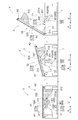
- 3 shows a state in which the article support portion 32 is inclined in the first inclination direction T1
- FIG. 4 shows a state in which the article support portion 32 is inclined in the second inclination direction T2.
- the transfer device 3 includes the article support portion 32 that supports the article W from below, the connection support portion 31 that connects the article support portion 32 and the trolley body 1, and the inclination that inclines the article support portion 32. And a transfer driving unit D (corresponding to a driving unit) that performs driving.
- the connection support portion 31 has a first shaft support portion 311 that is swingably connected to the carriage body 1 around a first axis A1 along the reference axis direction A. ing.
- the connection support portion 31 has a pressed portion that is pressed by the first pressing portion 332 of the first drive portion 33D.
- the pressed portion is the first sliding portion 312 on which the first pressing portion 332 can slide while being pressed by the first pressing portion 332.
- the first sliding portion 312 is formed with a first bulging portion 313 that bulges downward as it approaches the first shaft support portion 311. It should be noted that in this case, "to bulge downward" is based on the state where the article support portion 32 is not tilted (not driven). The same applies to the following description.
- the first bulging portion 313 has a first arcuate portion 313a having an upwardly convex arcuate shape and a downwardly convex arcuate shape when viewed in the reference axial direction A. And a second arc-shaped portion 313b which is These are arranged in the order of the first arc-shaped portion 313a and the second arc-shaped portion 313b from the side farther from the first shaft support portion 311, and form a curved surface that is continuous in an S shape.
- connection support portion 31 has a horizontal surface in a non-inclined state.
- the first pressing portion 332 of the first driving portion 33D is connected and supported while sliding the first sliding portion 312 including the first arc-shaped portion 313a and the second arc-shaped portion 313b. It is configured to press the portion 31.
- the article support portion 32 has a second shaft support portion 321 that is swingably connected to the connection support portion 31 about a second axis A2 along the reference axis direction A. doing.
- the article support portion 32 has a pressed portion that is pressed by the second pressing portion 342 of the second drive portion 34D.
- this pressed portion is a second sliding portion 322 on which the second pressing portion 342 can slide while being pressed by the second pressing portion 342.
- the second sliding portion 322 is arranged on the outer side of the trolley body 1 in the reference axial direction A than the first sliding portion 312.
- the second sliding portion 322 is formed with a second bulging portion 323 that bulges downward as it approaches the second shaft support portion 321.
- the second bulging portion 323 has a third arcuate portion 323a that is an upwardly convex arcuate shape and a downwardly convex arcuate shape when viewed in the reference axial direction A. And a fourth arc-shaped portion 323b which is These are arranged in order of the third arcuate portion 323a and the fourth arcuate portion 323b from the side distant from the second shaft support portion 321, and form a continuous curved surface in an S shape.
- the end of the third arcuate portion 323a farther from the second shaft support 321 and the end of the fourth arcuate portion 323b closer to the second shaft support 321 are both Also has a horizontal surface in a state where the article support portion 32 is not inclined.
- the second pressing portion 342 of the second drive portion 34D supports the article while sliding on the second sliding portion 322 including the third arc-shaped portion 323a and the fourth arc-shaped portion 323b. It is configured to press the portion 32.
- the article support unit 32 has a support base 324 that supports the article W.
- the support base 324 in this example is configured by a plate-shaped member that spreads in a plane along the reference axis direction A, and the carriage main body 1 is in a state where the article support portion 32 is not inclined. Is formed so as to cover the upper surface of the.
- the support base 324 does not have a protruding portion protruding upward at least at both ends (or in the vicinity thereof) in the direction C orthogonal to the reference axis. As a result, it is possible to properly slide the article W supported by the support base 324 onto the article input section 80 when the article support section 32 is in the inclined state.
- the support base 324 is formed in a rectangular plate shape, but the support base 324 is not limited to such an example, and the support base 324 may be a circular plate shape, an octagonal plate shape, or the like. It may have a variety of shapes that can be supported.
- the article support portion 32 is arranged above the connection support portion 31 and across the connection support portion 31 in the reference axial direction A. That is, when the article support portion 32 is not swinging around the second axis A2, the article support portion 32 is configured to contact the connection support portion 31 from above. As a result, the article support portion 32 is restricted from swinging below the connection support portion 31 by the connection support portion 31. Therefore, when the connection support part 31 swings upward around the first axis A1, the article support part 32 is pushed from below by the connection support part 31 and rotates around the first axis A1 together with the connection support part 31. Rock upwards.
- connection support portion 31 is configured so as to come into contact with a part (abutted portion (not shown)) of the bogie body 1 from above in a state where it is not swinging around the first axis A1 (horizontal state in this example). Is configured. As a result, the swing of the connection support portion 31 from the horizontal state to the lower side is restricted by the abutted portion of the carriage body 1.
- the first drive unit 33D transmits the driving force to the connection support unit 31 to move the connection support unit 31 and the article support unit 32 connected to the connection support unit 31 into the first drive unit 33D.
- the article support section 32 is configured to be tilted in the first tilt direction T1 by swinging about the axis A1.
- the first driving unit 33D transmits the driving force upward from the center side of the bogie body 1 in the direction C orthogonal to the first axis A1 in the reference axis orthogonal direction C to the coupling support unit 31.
- the coupling support portion 31 is swung upward and in the direction C orthogonal to the reference axis from the center of the bogie body 1 toward the first axis A1.
- the first drive section 33D swings the connection support section 31 counterclockwise about the first axis A1. As described above, since the article support portion 32 is restricted from swinging downward from the connection support portion 31, the article support portion 32 also moves upward as the connection support portion 31 swings upward. Rock. Thereby, the first drive unit 33D tilts the article support unit 32 in the first tilt direction T1.
- the first drive part 33D includes a first arm part 331 connected to the carriage body 1 and a first pressing part 332 connected to the first arm part 331 and pressing the connection support part 31 from below. , And a first drive source M1 for driving the first arm portion 331.
- the first arm portion 331 is rotatably connected to the carriage main body 1 around the third axis A3 along the reference axis direction A.
- the first arm portion 331 includes the first pressing portion 332 and the third shaft A3 between the third axis A3 side and the first pressing portion 332 side. It has the 1st bending part 331a bent so that it may go toward the connection support part 31 side toward it. Accordingly, a part of the load applied to the first arm portion 331 as a bending stress when the first support portion 332 is pressed by the first pressing portion 332 can be a compressive stress, and the durability of the first arm portion 331 can be improved. Can be improved.
- the first pressing portion 332 is connected to the first arm portion 331 at a position away from the third axis A3, and slides with respect to the connection support portion 31 while rotating around the third axis A3 together with the first arm portion 331.
- the connection support portion 31 is configured to be pressed.
- the first pressing portion 332 is configured to slide along the first sliding portion 312 of the connection support portion 31.
- the first pressing portion 332 includes a roller that rotates around an axis along the reference axis direction A.
- the first drive source M1 is configured as an electric motor, and drives the first arm portion 331 to rotate about the third axis A3.
- the first drive source M1 operates according to a command from the individual control device Cv.
- the third axis A3 which is the center of rotation of the first arm portion 331, is arranged closer to the center of the trolley body 1 in the direction C orthogonal to the reference axis than the first axis A1. Further, the third axis A3 is also arranged on the center side of the carriage main body 1 in the direction C orthogonal to the reference axis with respect to the second axis A2. However, without being limited to the above configuration, the third axis A3 may be arranged outside the trolley body 1 in the direction C orthogonal to the reference axis with respect to the first axis A1, or the second axis A3. It may be arranged outside the trolley body 1 in the direction C orthogonal to the reference axis with respect to the axis A2.
- the second driving section 34D transmits the driving force to the article supporting section 32, thereby swinging the article supporting section 32 around the second axis A2 to move the article supporting section 32. It is configured to be tilted in a second tilt direction T2 different from the first tilt direction T1.
- the second drive unit 34D transmits the drive force upward from the center side of the trolley body 1 in the direction C orthogonal to the second axis A2 in the reference axis orthogonal direction C to the article support unit 32.
- the article support portion 32 is swung upward and in the direction C orthogonal to the reference axis from the center of the carriage body 1 toward the second axis A2.
- FIG. 1 the example shown in FIG.
- the second drive section 34D swings the article support section 32 clockwise around the second axis A2.
- the article support portion 32 is only in contact with the connection support portion 31 from above, and therefore swings around the second axis A2.
- the second drive unit 34D tilts only the article support unit 32 in the second tilt direction T2 without tilting (swinging) the connection support unit 31.
- the second drive unit 34D includes a second arm unit 341 connected to the carriage main body 1 and a second pressing unit 342 connected to the second arm unit 341 and pressing the article support unit 32 from below. , And a second drive source M2 for driving the second arm portion 341.
- the second arm portion 341 is rotatably connected to the carriage main body 1 around the fourth axis A4 along the reference axis direction A.
- the second arm portion 341 is arranged between the second pressing portion 342 and the fourth shaft A4 from the fourth shaft A4 side to the second pressing portion 342 side. It has the 2nd bending part 341a which bends so that it may go toward the article support part 32 side toward it.
- a part of the load applied to the second arm portion 341 as a bending stress when the second pressing portion 342 presses the article support portion 32 can be a compressive stress, and the durability of the second arm portion 341 can be improved. Can be improved.
- the second pressing portion 342 is connected to the second arm portion 341 at a position apart from the fourth axis A4, and slides with respect to the article support portion 32 while rotating around the fourth axis A4 together with the second arm portion 341. As a result, the article support section 32 is configured to be pressed. As described above, the second pressing portion 342 is configured to slide along the second sliding portion 322 of the article support portion 32.
- the second pressing portion 342 includes a roller that rotates around an axis along the reference axis direction A.
- the second drive source M2 is configured as an electric motor, and drives the second arm portion 341 to rotate about the fourth axis A4.
- the second drive source M2 operates according to a command from the individual control device Cv.
- the fourth axis A4 which is the center of rotation of the second arm portion 341, is arranged closer to the center of the bogie body 1 in the direction C orthogonal to the reference axis than the second axis A2. Further, the fourth axis A4 is also arranged on the center side of the carriage main body 1 in the reference axis orthogonal direction C with respect to the first axis A1. However, without being limited to the above configuration, the fourth axis A4 may be arranged outside the trolley body 1 in the direction C orthogonal to the reference axis with respect to the second axis A2, or the first axis A4. It may be arranged outside the trolley body 1 in the direction C orthogonal to the reference axis with respect to the axis A1.
- the third axis A3 and the fourth axis A4 are the common axis AS.
- the common axis AS is arranged between the first axis A1 and the second axis A2 when viewed in the vertical direction.
- the common axis AS is arranged at an intermediate position between the first axis A1 and the second axis A2 when viewed in the vertical direction.
- first arm portion 331 and the second arm portion 341 are connected so as to integrally rotate about the common axis AS, and extend in different directions from the common axis AS. It is arranged. In the present embodiment, the first arm portion 331 and the second arm portion 341 are arranged so as to extend in opposite directions (directions different by 180°) when viewed in the reference axis direction A. The first arm portion 331 and the second arm portion 341 are integrally formed by one member.
- the second sliding portion 322 of the article support portion 32 is arranged outside the first sliding portion 312 of the connection support portion 31 on the outside of the carriage main body 1 in the reference axis direction A.
- the first pressing portion 332 connected to the first arm portion 331 is configured to slide on the first sliding portion 312, and the second pressing portion connected to the second arm portion 341.
- the 342 is configured to slide with respect to the second sliding portion 322. Therefore, in this example, as shown in FIGS. 3 and 4, the first pressing portion 332 that contacts (slides) the first sliding portion 312 and the second pressing portion 332 that contacts (slides) the second sliding portion 322.
- the first pressing portion 332 side of the first arm portion 331 is located inside the bogie body 1 in the reference axis direction A with respect to the common axis AS side of the first arm portion 331.
- the first arm portion 331 is bent so as to be located at.
- the first arm portion 331 and the second arm portion 341 are connected to the common axis AS
- the first pressing portion 332 slides with respect to the first sliding portion 312, and
- the second pressing portion 342 is configured to slide on the second sliding portion 322.
- the first drive source M1 and the second drive source M2 are common drive sources MS.
- the common drive source MS applies a rotational force to the common axis AS, the first arm section 331 and the second arm section 341 connected to the common axis AS rotate.
- the common drive source MS is configured as an electric motor.
- FIG. 5 shows the operation when the article support unit 32 is tilted in the first tilt direction T1.
- the driving force is transmitted to the connection support portion 31 by the first drive portion 33D, and the article support portion 32 is tilted together with the connection support portion 31.
- the first drive portion 33D is connected to the connection support portion 31 in the direction in which the first pressing portion 332 approaches the first shaft support portion 311.
- the first drive source M1 rotationally drives the first arm portion 331 so as to slide.
- the common drive source MS rotationally drives the first arm portion 331 and the second arm portion 341 around the common axis AS.
- the first arm portion 331 is swung around the third axis A3 (common axis AS)
- the connection support portion 31 is pressed from below by the first pressing portion 332, and the connection support portion 31 and the article support portion 32. Is lifted upward (see the central view of FIG. 5).
- the first pressing portion 332 sequentially moves the first arc-shaped portion 313a and the second arc-shaped portion 313b of the first bulging portion 313.
- the connection support 31 is pressed while sliding.
- the article support portion 32 is tilted in the first tilt direction T1 (see the right diagram in FIG. 5). Therefore, the article W supported by the support base 324 of the article support section 32 can be slid down onto the article input section 80 (see FIG. 1), and as a result, the article W is transferred to the article input section 80. Can be posted.
- the first bulging portion 313 by forming the first bulging portion 313 on the first sliding portion 312, it is possible to secure a large inclination angle of the article support portion 32 with respect to the length of the first arm portion 331. Further, since the first bulging portion 313 has the first arcuate portion 313a and the second arcuate portion 313b, the inclination speed during the inclination of the article support portion 32 in the first inclination direction T1 is It is configured to change appropriately. That is, while the first pressing portion 332 slides on the first arcuate portion 313a having an upward convex arcuate shape, the inclination speed of the article support portion 32 gradually increases.
- the inclination speed of the article support portion 32 gradually decreases. This makes it possible to maintain a high average tilting speed when tilting the article support portion 32 in the first tilting direction T1, while suppressing the tilting speed at the start and end of the change in the tilt angle to be low. Therefore, the cycle time when transferring the article W can be shortened, and the article W supported by the article supporting portion 32 can be prevented from being lifted from the article supporting portion 32 to appropriately transfer the article W. It is possible to do.
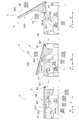
- FIG. 6 shows the operation when the article support portion 32 is tilted in the second tilt direction T2.
- the driving force is transmitted to the article support portion 32 by the second driving portion 34D to tilt the article support portion 32.
- the second driving unit 34D is configured to move the second supporting unit 342 from the horizontal state where the product supporting unit 32 is not tilted (see the left diagram in FIG. 6) in the direction in which the second pressing unit 342 approaches the second shaft supporting unit 321 with respect to the product supporting unit 32.
- the second arm portion 341 is rotationally driven by the second drive source M2 so as to slide.
- the common drive source MS rotationally drives the first arm portion 331 and the second arm portion 341 around the common axis AS.
- the second arm portion 341 is swung around the fourth axis A4 (common axis AS), and the article support portion 32 is pressed from below by the second pressing portion 342 and lifted upward (see the central view of FIG. 6). ).
- the second pressing portion 342 sequentially moves the third arc-shaped portion 323a and the fourth arc-shaped portion 323b of the second bulging portion 323.
- the article support portion 32 is pressed while sliding.
- the article support portion 32 is tilted in the second tilt direction T2 (see the right diagram in FIG. 6). Therefore, the article W supported by the support base 324 of the article support section 32 can be slid down onto the article input section 80 (see FIG. 1), and as a result, the article W is transferred to the article input section 80. Can be posted.
- the second swelling portion 323 is formed on the second sliding portion 322, a large inclination angle of the article support portion 32 can be secured with respect to the length of the second arm portion 341.
- the second bulging portion 323 has the third arc-shaped portion 323a and the fourth arc-shaped portion 323b, the inclination speed during the inclination of the article support portion 32 in the second inclination direction T2 is It is configured to change appropriately. That is, while the second pressing portion 342 slides on the upwardly convex third arcuate portion 323a, the inclination speed of the article support portion 32 gradually increases.
- the inclination speed of the article support portion 32 gradually decreases.
- the cycle time when transferring the article W can be shortened, and the article W supported by the article supporting portion 32 can be prevented from being lifted from the article supporting portion 32 to appropriately transfer the article W. It is possible to do.
- the common drive source MS rotationally drives the first arm portion 331 in the first rotation direction (counterclockwise direction in FIG. 5) to move the article support portion 32 in the first tilt direction T1. It can be tilted, and the common drive source MS rotationally drives the second arm portion 341 in the second rotation direction (clockwise direction in FIG. 6) opposite to the first rotation direction to move the article support portion 32 to the first rotation direction. It can be tilted in two tilt directions T2. That is, in the present embodiment, the common drive source MS causes the connection support portion 31 to swing about the first axis A1 to incline the article support portion 32 in the first inclination direction T1 and the case where the article support portion 32 is moved to the second inclination direction.
- the article transporting vehicle V as a whole can be downsized by sharing the configuration of swinging the connection support portion 31 and the configuration of swinging the article support portion 32.
- the third axis A3, which is the rotation center of the first arm portion 331, and the fourth axis A4, which is the rotation center of the second arm portion 341, are common axes AS that are common to each other.
- the first drive source M1 that rotationally drives the first arm portion 331 and the second drive source M2 that rotationally drives the second arm portion 341 are common drive sources MS that are common to each other.
- the third axis A3 and the fourth axis A4 may be axes different from each other, and the first drive source M1 and the second drive source M1 may be different from each other.
- the driving source M2 may be provided as a driving force source independent of each other.
- the first drive unit 33D is configured to have the first arm unit 331 that rotates about the third axis A3, and the second drive unit 34D rotates about the fourth axis A4.
- the example in which the second arm portion 341 is provided is described.
- the first drive unit 33D and the second drive unit 34D may be configured as linear motion actuators that perform expansion/contraction drive.
- a linear motion actuator for example, an electric motor that operates by receiving power supply from a battery mounted on the article transport vehicle V, and a rotational driving force of the electric motor is converted into a linear driving force of a cylinder shaft.
- a direct-acting cylinder type actuator provided with a conversion mechanism such as a ball screw or a worm gear can be preferably used.
- one end of the first linear motion actuator (first drive unit 33D) that swings the connection support portion 31 around the first axis A1 has a center CC in the connection support portion 31 in the direction C orthogonal to the reference axis. It is better to be swingably connected to the connection support portion 31 on the second axis A2 side. Further, the other end of the first linear motion actuator (first drive portion 33D) may be swingably connected to the carriage main body 1.
- the driving force transmitted to the connection support portion 31 by the first linear motion actuator is appropriately transmitted as the drive force for swinging the connection support portion 31 around the first axis A1.
- the second linear motion actuator (second drive unit 34D) that swings the article support unit 32 around the second axis A2 has one end portion thereof located closer to the center CC of the article support unit 32 in the direction C orthogonal to the reference axis.
- the first axis A1 side is preferably swingably connected to the article support portion 32.
- the other end of the second linear motion actuator may be swingably connected to the trolley body 1.
- the driving force transmitted to the article supporting unit 32 by the second linear motion actuator (second driving unit 34D) is appropriately transmitted as the driving force for swinging the article supporting unit 32 around the second axis A2.
- FIG. 8 shows an example in which both the first drive unit 33D and the second drive unit 34D are configured as linear actuators, the first drive unit 33D and the second drive unit 34D are different. It may be a drive unit of a type.
- the width of the support base 324 in the direction C orthogonal to the reference axis is the same as the width of the carriage main body 1 in the direction C orthogonal to the reference axis has been described as an example in FIG. 2.
- the width of the support base 324 in the reference axis orthogonal direction C is configured to be larger than the width of the carriage main body 1 in the reference axis orthogonal direction C.
- the lower end of the support base 324 in a state where the article support section 32 is inclined can be brought close to the floor surface 70 and the article input section 80. Therefore, it is possible to directly insert the article W into the insertion port 81 of the article insertion section 80 without using the guide section 82 as shown in FIG.
- first bulging portion 313 is formed on the first sliding portion 312 and the second bulging portion 323 is formed on the second sliding portion 322 has been described.
- first sliding portion 312 and the second sliding portion 322 may be formed in a linear shape when viewed in the reference axis direction A.
- An article transporting vehicle comprising: a trolley body; and a transfer device that is mounted on the trolley body to transfer an article, wherein the transfer apparatus includes an article support portion that supports the article from below, and the article.
- the connection support part includes a connection support part that connects the support part and the trolley body, and a drive part that performs an inclination drive to incline the article support part, and the connection support part is one direction along the horizontal direction as a reference axis direction.
- Has a first shaft support portion swingably connected to the carriage main body around a first axis along the reference axis direction, and the article support portion is provided with respect to the connection support portion.
- the drive unit has a first drive unit and a second drive unit, and the first drive unit transmits a driving force to the connection support unit to thereby provide the connection support unit. And swinging the article support section connected to the connection support section around the first axis to incline the article support section in the first tilt direction, and the second drive section is configured to move the article support section to the article support section.
- the first drive section can swing the article support section around the first axis through the connection support section to tilt the article support section in the first inclination direction
- the second The drive section can swing the article support section around the second axis to incline the article support section in the second inclination direction. Therefore, according to this configuration, the article support portion can be tilted in two different directions, and the article supported by the article support portion can be slid down and transferred in two different directions.
- the tilting drive of the article support unit can be performed by the driving unit included in the article transport vehicle, a mechanism for tilting the article support unit is separately installed along the traveling route of the article transport vehicle. You don't have to. Therefore, there is a high degree of freedom in setting the travel route of the article transport vehicle, and the cost of equipment equipped with this article transport vehicle can be kept low.
- the first driving unit includes a first arm unit connected to the carriage main body, a first pressing unit connected to the first arm unit and pressing the connection support unit from below, and the first arm unit.
- a first drive source for driving the second drive section wherein the second drive section is connected to the trolley body and a second arm section, and is connected to the second arm section to press the article support section from below. It is preferable to have a second pressing portion and a second drive source that drives the second arm portion.
- the article support section is moved around the first axis or the second axis by the first drive source that drives the first arm section and the second drive source that drives the second arm section, respectively. It can be tilted in different directions. Therefore, it is possible to appropriately realize a configuration in which the article supported by the article support section can be transferred in two different directions.
- the first arm portion is rotatably connected to the carriage main body around a third axis along the reference axis direction
- the second arm portion is rotatably around a fourth axis along the reference axis direction.
- the first pressing portion is connected to the trolley body, the first pressing portion is connected to a position apart from the third axis in the first arm portion, and the connection support portion is rotated together with the first arm portion around the third axis. It is configured to press the connection support part by sliding with respect to the second support part.
- the second press part is connected to a position of the second arm part away from the fourth axis, and the second arm part is connected to the second arm part.
- the first drive source rotationally drives the first arm portion so as to slide in the direction relative to the connection support portion, and the second pressing portion approaches the second shaft support portion in the direction to support the article. It is preferable that the second drive source rotationally drives the second arm portion so as to slide with respect to the portion.
- the driving force transmitted to the coupling support portion via the first pressing portion can be appropriately transmitted as the driving force required to rotate the coupling support portion around the first axis.
- the driving force transmitted to the article supporting portion via the second pressing portion can be appropriately transmitted as the driving force required to rotate the article supporting portion around the second axis.
- the third shaft and the fourth shaft are a common shaft that is common, and the common shaft is disposed between the first shaft and the second shaft when viewed in the up-down direction.
- the second arm portion is connected so as to integrally rotate around the common axis, and is arranged so as to extend in different directions from the common axis.
- Two drive sources are a common common drive source, and the common drive source swings the connection support portion around the first axis and swings the article support portion around the second axis. It is preferable that the first arm portion and the second arm portion are rotationally driven in opposite directions around the common axis.
- the configuration of swinging the connection support portion around the first axis and the configuration of swinging the article support portion around the second axis can be made common, and the article transport vehicle as a whole can be downsized. it can.
- a first swelling portion that bulges downward as it approaches the first shaft support portion is formed in a first sliding portion on which the first pressing portion of the connection support portion slides; It is preferable that the second sliding portion on which the second pressing portion of the article support portion slides is provided with a second bulging portion that bulges downward as it approaches the second shaft support portion.
- the article support portion of the article support portion can be compared with a case where the first bulge portion is not provided.
- the length of the first arm portion can be set short while ensuring the inclination angle.
- the second pressing portion can press the article support portion via the second bulge portion, so that the inclination angle of the article support portion can be reduced as compared with the case where the second bulge portion is not provided.
- the length of the second arm portion can be set short while ensuring the length. Therefore, according to this configuration, the lengths of the first arm portion and the second arm portion can be set to be relatively short, so that it is possible to prevent the article transport vehicle from increasing in size.
- the technology according to the present disclosure can be used for an article transport vehicle including a trolley body and a transfer device that is mounted on the trolley body to transfer articles.
- V article transport vehicle
- D transfer drive unit (drive unit)
- W article 1: carriage main body 3: transfer device 31: connection support section 32: article support section 33D: first drive section 34D: second drive section 311: first shaft support section 312: first sliding section 313: first 1 bulge part 321: 2nd shaft support part 322: 2nd sliding part 323: 2nd bulge part 331: 1st arm part 332: 1st press part 341: 2nd arm part 342: 2nd press part M1: First drive source M2: Second drive source MS: Common drive source A1: First axis A2: Second axis A3: Third axis A4: Fourth axis AS: Common axis A: Reference axis direction C: Reference axis orthogonal direction T1: First tilt direction T2: Second tilt direction
Landscapes
- Engineering & Computer Science (AREA)
- Mechanical Engineering (AREA)
- Transportation (AREA)
- Warehouses Or Storage Devices (AREA)
- Discharge Of Articles From Conveyors (AREA)
- Intermediate Stations On Conveyors (AREA)
- Chain Conveyers (AREA)
- Handcart (AREA)
- Aviation & Aerospace Engineering (AREA)
Abstract
Description
台車本体と、前記台車本体に搭載されて物品を移載する移載装置と、を備えた物品搬送車であって、前記移載装置は、物品を下方から支持する物品支持部と、前記物品支持部と前記台車本体とを連結する連結支持部と、前記物品支持部を傾斜させる傾斜駆動を行う駆動部と、を有し、水平方向に沿う一方向を基準軸方向として、前記連結支持部は、前記台車本体に対して、前記基準軸方向に沿う第1軸周りに揺動可能に連結された第1軸支部を有し、前記物品支持部は、前記連結支持部に対して、前記基準軸方向に沿う第2軸周りに揺動可能に連結された第2軸支部を有し、前記第1軸と前記第2軸とは、前記基準軸方向に沿う基準軸方向視において互いに異なる位置に配置され、前記駆動部は、第1駆動部と第2駆動部とを有し、前記第1駆動部は、前記連結支持部に対して駆動力を伝達することで、前記連結支持部および当該連結支持部に連結された前記物品支持部を前記第1軸周りに揺動させて、前記物品支持部を第1傾斜方向に傾斜させ、前記第2駆動部は、前記物品支持部に対して駆動力を伝達することで、前記物品支持部を前記第2軸周りに揺動させて、前記物品支持部を前記第1傾斜方向とは異なる第2傾斜方向に傾斜させる。
第1実施形態に係る物品搬送車について図面を参照して説明する。以下では、物品搬送車が、物品の搬送及び仕分けを行う物品搬送設備に適用される場合を例に説明する。
図1に示すように、物品搬送設備Fは、物品Wを搬送する物品搬送車Vと、物品搬送車Vによって搬送された物品Wが投入される物品投入部80と、を備えている。この物品搬送設備Fでは、例えば、物品Wの種類や出荷先などの特定情報に基づいて指定された物品投入部80に物品Wが投入されることによって、複数の物品Wが種類や出荷先などの特定情報ごとに仕分けられる。図示の例では、複数の物品投入部80が設備の床面70に設けられていると共に、床面70上に物品搬送車Vの走行経路が設定されている。そして、複数の物品搬送車Vのそれぞれが、走行経路に沿って走行して、種類や出荷先などの特定情報に基づいて指定された物品投入部80に物品Wを搬送するように構成されている。
次に、物品搬送車Vの概略的構成について、物品搬送車Vの構成を概念的に示した図2を参照して説明する。
次に、移載装置3の具体的構成について説明する。移載装置3は、物品支持部32を第1傾斜方向T1又は第2傾斜方向T2に傾斜させることによって、物品Wを移載するように構成されている。図3は、物品支持部32が第1傾斜方向T1に傾斜している状態を示しており、図4は、物品支持部32が第2傾斜方向T2に傾斜している状態を示している。
次に、物品支持部32の動作について、図5及び図6を参照して説明する。
次に、物品搬送車のその他の実施形態について説明する。
しかし、このような例に限定されることなく、例えば図7に示すように、第3軸A3と第4軸A4とは、互いに別軸であってもよく、第1駆動源M1と第2駆動源M2とは、互いに独立の駆動力源として設けられていてもよい。
以下、上記において説明した物品搬送車について説明する。
台車本体と、前記台車本体に搭載されて物品を移載する移載装置と、を備えた物品搬送車であって、前記移載装置は、物品を下方から支持する物品支持部と、前記物品支持部と前記台車本体とを連結する連結支持部と、前記物品支持部を傾斜させる傾斜駆動を行う駆動部と、を有し、水平方向に沿う一方向を基準軸方向として、前記連結支持部は、前記台車本体に対して、前記基準軸方向に沿う第1軸周りに揺動可能に連結された第1軸支部を有し、前記物品支持部は、前記連結支持部に対して、前記基準軸方向に沿う第2軸周りに揺動可能に連結された第2軸支部を有し、前記第1軸と前記第2軸とは、前記基準軸方向に沿う基準軸方向視において互いに異なる位置に配置され、前記駆動部は、第1駆動部と第2駆動部とを有し、前記第1駆動部は、前記連結支持部に対して駆動力を伝達することで、前記連結支持部および当該連結支持部に連結された前記物品支持部を前記第1軸周りに揺動させて、前記物品支持部を第1傾斜方向に傾斜させ、前記第2駆動部は、前記物品支持部に対して駆動力を伝達することで、前記物品支持部を前記第2軸周りに揺動させて、前記物品支持部を前記第1傾斜方向とは異なる第2傾斜方向に傾斜させる。
前記第1駆動部は、前記台車本体に連結された第1アーム部と、前記第1アーム部に連結されて前記連結支持部を下方から押圧する第1押圧部と、前記第1アーム部を駆動する第1駆動源と、を有し、前記第2駆動部は、前記台車本体に連結された第2アーム部と、前記第2アーム部に連結されて前記物品支持部を下方から押圧する第2押圧部と、前記第2アーム部を駆動する第2駆動源と、を有していると好適である。
前記第1アーム部は、前記基準軸方向に沿う第3軸周りに回転可能に前記台車本体に連結され、前記第2アーム部は、前記基準軸方向に沿う第4軸周りに回転可能に前記台車本体に連結され、前記第1押圧部は、前記第1アーム部における前記第3軸から離れた位置に連結され、前記第1アーム部と共に前記第3軸周りに回転しつつ前記連結支持部に対して摺動することにより、前記連結支持部を押圧するように構成され、前記第2押圧部は、前記第2アーム部における前記第4軸から離れた位置に連結され、前記第2アーム部と共に前記第4軸周りに回転しつつ前記物品支持部に対して摺動することにより、前記物品支持部を押圧するように構成され、前記第1押圧部が前記第1軸支部に接近する方向に前記連結支持部に対して摺動するように、前記第1駆動源が前記第1アーム部を回転駆動し、前記第2押圧部が前記第2軸支部に接近する方向に前記物品支持部に対して摺動するように、前記第2駆動源が前記第2アーム部を回転駆動すると好適である。
前記第3軸と前記第4軸とが共通の共通軸とされ、前記共通軸は、上下方向視で、前記第1軸と前記第2軸との間に配置され、前記第1アーム部と前記第2アーム部とが、前記共通軸周りに一体的に回転するように連結されていると共に、前記共通軸から互いに異なる方向に延在するように配置され、前記第1駆動源と前記第2駆動源とが共通の共通駆動源であり、前記共通駆動源は、前記連結支持部を前記第1軸周りに揺動させる場合と前記物品支持部を前記第2軸周りに揺動させる場合とで、前記第1アーム部及び前記第2アーム部を前記共通軸周りの互いに反対方向に回転駆動すると好適である。
前記連結支持部における前記第1押圧部が摺動する第1摺動部に、前記第1軸支部に接近するに従って下方に膨出する第1膨出部が形成され、
前記物品支持部における前記第2押圧部が摺動する第2摺動部に、前記第2軸支部に接近するに従って下方に膨出する第2膨出部が形成されていると好適である。
D :移載駆動部(駆動部)
W :物品
1 :台車本体
3 :移載装置
31 :連結支持部
32 :物品支持部
33D :第1駆動部
34D :第2駆動部
311 :第1軸支部
312 :第1摺動部
313 :第1膨出部
321 :第2軸支部
322 :第2摺動部
323 :第2膨出部
331 :第1アーム部
332 :第1押圧部
341 :第2アーム部
342 :第2押圧部
M1 :第1駆動源
M2 :第2駆動源
MS :共通駆動源
A1 :第1軸
A2 :第2軸
A3 :第3軸
A4 :第4軸
AS :共通軸
A :基準軸方向
C :基準軸直交方向
T1 :第1傾斜方向
T2 :第2傾斜方向
Claims (5)
- 台車本体と、前記台車本体に搭載されて物品を移載する移載装置と、を備えた物品搬送車であって、
前記移載装置は、物品を下方から支持する物品支持部と、前記物品支持部と前記台車本体とを連結する連結支持部と、前記物品支持部を傾斜させる傾斜駆動を行う駆動部と、を有し、
水平方向に沿う一方向を基準軸方向として、
前記連結支持部は、前記台車本体に対して、前記基準軸方向に沿う第1軸周りに揺動可能に連結された第1軸支部を有し、
前記物品支持部は、前記連結支持部に対して、前記基準軸方向に沿う第2軸周りに揺動可能に連結された第2軸支部を有し、
前記第1軸と前記第2軸とは、前記基準軸方向に沿う基準軸方向視において互いに異なる位置に配置され、
前記駆動部は、第1駆動部と第2駆動部とを有し、
前記第1駆動部は、前記連結支持部に対して駆動力を伝達することで、前記連結支持部および当該連結支持部に連結された前記物品支持部を前記第1軸周りに揺動させて、前記物品支持部を第1傾斜方向に傾斜させ、
前記第2駆動部は、前記物品支持部に対して駆動力を伝達することで、前記物品支持部を前記第2軸周りに揺動させて、前記物品支持部を前記第1傾斜方向とは異なる第2傾斜方向に傾斜させる、物品搬送車。 - 前記第1駆動部は、前記台車本体に連結された第1アーム部と、前記第1アーム部に連結されて前記連結支持部を下方から押圧する第1押圧部と、前記第1アーム部を駆動する第1駆動源と、を有し、
前記第2駆動部は、前記台車本体に連結された第2アーム部と、前記第2アーム部に連結されて前記物品支持部を下方から押圧する第2押圧部と、前記第2アーム部を駆動する第2駆動源と、を有している、請求項1に記載の物品搬送車。 - 前記第1アーム部は、前記基準軸方向に沿う第3軸周りに回転可能に前記台車本体に連結され、
前記第2アーム部は、前記基準軸方向に沿う第4軸周りに回転可能に前記台車本体に連結され、
前記第1押圧部は、前記第1アーム部における前記第3軸から離れた位置に連結され、前記第1アーム部と共に前記第3軸周りに回転しつつ前記連結支持部に対して摺動することにより、前記連結支持部を押圧するように構成され、
前記第2押圧部は、前記第2アーム部における前記第4軸から離れた位置に連結され、前記第2アーム部と共に前記第4軸周りに回転しつつ前記物品支持部に対して摺動することにより、前記物品支持部を押圧するように構成され、
前記第1押圧部が前記第1軸支部に接近する方向に前記連結支持部に対して摺動するように、前記第1駆動源が前記第1アーム部を回転駆動し、
前記第2押圧部が前記第2軸支部に接近する方向に前記物品支持部に対して摺動するように、前記第2駆動源が前記第2アーム部を回転駆動する、請求項2に記載の物品搬送車。 - 前記第3軸と前記第4軸とが共通の共通軸とされ、
前記共通軸は、上下方向視で、前記第1軸と前記第2軸との間に配置され、
前記第1アーム部と前記第2アーム部とが、前記共通軸周りに一体的に回転するように連結されていると共に、前記共通軸から互いに異なる方向に延在するように配置され、
前記第1駆動源と前記第2駆動源とが共通の共通駆動源であり、
前記共通駆動源は、前記連結支持部を前記第1軸周りに揺動させる場合と前記物品支持部を前記第2軸周りに揺動させる場合とで、前記第1アーム部及び前記第2アーム部を前記共通軸周りの互いに反対方向に回転駆動する、請求項3に記載の物品搬送車。 - 前記連結支持部における前記第1押圧部が摺動する第1摺動部に、前記第1軸支部に接近するに従って下方に膨出する第1膨出部が形成され、
前記物品支持部における前記第2押圧部が摺動する第2摺動部に、前記第2軸支部に接近するに従って下方に膨出する第2膨出部が形成されている、請求項3又は4に記載の物品搬送車。
Priority Applications (12)
| Application Number | Priority Date | Filing Date | Title |
|---|---|---|---|
| SG11202106440UA SG11202106440UA (en) | 2018-12-21 | 2019-08-30 | Article transport vehicle |
| CA3123532A CA3123532A1 (en) | 2018-12-21 | 2019-08-30 | Article transport vehicle |
| KR1020217020045A KR102636126B1 (ko) | 2018-12-21 | 2019-08-30 | 물품 반송차 |
| AU2019404982A AU2019404982B2 (en) | 2018-12-21 | 2019-08-30 | Article transport vehicle |
| MYPI2021003125A MY207789A (en) | 2018-12-21 | 2019-08-30 | Article transport vehicle |
| CN201980083735.6A CN113242812B (zh) | 2018-12-21 | 2019-08-30 | 物品搬运车 |
| CN202310240080.7A CN116022050B (zh) | 2018-12-21 | 2019-08-30 | 物品搬运车 |
| EP19898892.5A EP3885189A4 (en) | 2018-12-21 | 2019-08-30 | ARTICLE TRANSPORT VEHICLE |
| KR1020247004470A KR102748731B1 (ko) | 2018-12-21 | 2019-08-30 | 물품 반송차 |
| US17/414,575 US11673500B2 (en) | 2018-12-21 | 2019-08-30 | Article transport vehicle |
| US18/137,178 US12077084B2 (en) | 2018-12-21 | 2023-04-20 | Article transport vehicle |
| AU2025202286A AU2025202286A1 (en) | 2018-12-21 | 2025-03-31 | Article transport vehicle |
Applications Claiming Priority (2)
| Application Number | Priority Date | Filing Date | Title |
|---|---|---|---|
| JP2018240328A JP7014147B2 (ja) | 2018-12-21 | 2018-12-21 | 物品搬送車 |
| JP2018-240328 | 2018-12-21 |
Related Child Applications (2)
| Application Number | Title | Priority Date | Filing Date |
|---|---|---|---|
| US17/414,575 A-371-Of-International US11673500B2 (en) | 2018-12-21 | 2019-08-30 | Article transport vehicle |
| US18/137,178 Continuation US12077084B2 (en) | 2018-12-21 | 2023-04-20 | Article transport vehicle |
Publications (1)
| Publication Number | Publication Date |
|---|---|
| WO2020129322A1 true WO2020129322A1 (ja) | 2020-06-25 |
Family
ID=71101416
Family Applications (1)
| Application Number | Title | Priority Date | Filing Date |
|---|---|---|---|
| PCT/JP2019/034149 Ceased WO2020129322A1 (ja) | 2018-12-21 | 2019-08-30 | 物品搬送車(article transport vehicle) |
Country Status (11)
| Country | Link |
|---|---|
| US (2) | US11673500B2 (ja) |
| EP (1) | EP3885189A4 (ja) |
| JP (1) | JP7014147B2 (ja) |
| KR (2) | KR102748731B1 (ja) |
| CN (2) | CN113242812B (ja) |
| AU (2) | AU2019404982B2 (ja) |
| CA (1) | CA3123532A1 (ja) |
| MY (1) | MY207789A (ja) |
| SG (1) | SG11202106440UA (ja) |
| TW (2) | TWI852729B (ja) |
| WO (1) | WO2020129322A1 (ja) |
Cited By (4)
| Publication number | Priority date | Publication date | Assignee | Title |
|---|---|---|---|---|
| US20220105853A1 (en) * | 2020-10-06 | 2022-04-07 | Hyundai Motor Company | Delivery Package Loading Structure and Method in Cargo Container |
| EP4144671A1 (en) * | 2021-09-03 | 2023-03-08 | Daifuku Co., Ltd. | Article transport vehicle |
| EP4144672A1 (en) * | 2021-09-03 | 2023-03-08 | Daifuku Co., Ltd. | Article transport vehicle |
| EP4148003A1 (en) | 2021-09-03 | 2023-03-15 | Daifuku Co., Ltd. | Article transport vehicle |
Families Citing this family (7)
| Publication number | Priority date | Publication date | Assignee | Title |
|---|---|---|---|---|
| DE102020121883A1 (de) * | 2020-08-20 | 2022-02-24 | Fraunhofer-Gesellschaft zur Förderung der angewandten Forschung eingetragener Verein | Fahrzeug mit Ladegutaufnahme |
| JP7567706B2 (ja) * | 2021-07-21 | 2024-10-16 | 株式会社ダイフク | 架台ユニット |
| JP7559779B2 (ja) * | 2022-01-31 | 2024-10-02 | 株式会社ダイフク | 物品仕分け設備 |
| JP7822828B2 (ja) * | 2022-02-28 | 2026-03-03 | 株式会社東芝 | システム |
| JP7816222B2 (ja) * | 2023-03-06 | 2026-02-18 | 株式会社ダイフク | 物品搬送車 |
| JP7806776B2 (ja) * | 2023-10-24 | 2026-01-27 | 株式会社ダイフク | 物品仕分け設備 |
| JP2025082023A (ja) * | 2023-11-16 | 2025-05-28 | 株式会社ダイフク | 物品仕分け設備 |
Citations (5)
| Publication number | Priority date | Publication date | Assignee | Title |
|---|---|---|---|---|
| JPH06298348A (ja) | 1993-04-19 | 1994-10-25 | Kawasaki Heavy Ind Ltd | 荷物搬送仕分け設備 |
| US8100623B2 (en) * | 2009-08-07 | 2012-01-24 | Rogers Ralph R | Recycle container transfer vehicle |
| JP2012126238A (ja) * | 2010-12-15 | 2012-07-05 | Nippon Yusoki Co Ltd | 自動搬送車 |
| KR20180079692A (ko) * | 2017-01-02 | 2018-07-11 | 곽미영 | 무인 운반차 |
| JP2018520967A (ja) * | 2015-06-25 | 2018-08-02 | アマゾン テクノロジーズ インコーポレイテッド | 安定性制御のための傾斜プラットフォーム |
Family Cites Families (33)
| Publication number | Priority date | Publication date | Assignee | Title |
|---|---|---|---|---|
| US10441A (en) * | 1854-01-24 | Dumpih g-cail | ||
| US822360A (en) * | 1905-06-22 | 1906-06-05 | Robert F Gilchrist | Beet-rack. |
| US858364A (en) * | 1906-09-08 | 1907-07-02 | Edwin Henry Armatage | Dumping-vehicle. |
| US1831489A (en) * | 1928-02-09 | 1931-11-10 | Flowers Henry Fort | Three way dump vehicle |
| US3386563A (en) | 1966-12-19 | 1968-06-04 | Spra Con Co | Machine for the sortation of mail and other packages |
| US3848728A (en) | 1973-02-01 | 1974-11-19 | Butz Eng Corp | Conveyor and sorting system |
| SE414744B (sv) * | 1977-03-17 | 1980-08-18 | Jan Erik Lindholm | Anordning for sidotippning av en lastbehallare vid lastbilar |
| IT8520636U1 (it) * | 1985-01-29 | 1986-07-29 | Canziani Francesco | Carrello in particolare per smistatrici a piattelli ribaltabili |
| US4672014A (en) | 1985-10-08 | 1987-06-09 | The Mead Corporation | Exposure of imaging sheets utilizing a light valve as a wavelength transformer |
| DE3538296A1 (de) * | 1985-10-29 | 1987-04-30 | Friedrich Steinkuhle Kg Friste | Dreiseitenkippfahrzeug |
| JPS6457124A (en) | 1987-08-28 | 1989-03-03 | Power Reactor & Nuclear Fuel | Liquid level flowmeter |
| JPH02145124A (ja) * | 1988-11-25 | 1990-06-04 | Sochi Shikenjo | ロールベーラの放出位置制御装置 |
| NL9200766A (nl) * | 1992-04-28 | 1993-11-16 | Vanderlande Ind Nederland | Transportinrichting. |
| DE4314802A1 (de) * | 1993-05-05 | 1994-11-17 | Dautel Ratio Gmbh | Transportfahrzeug zum Transport von Wechselbehältern |
| CN1167056A (zh) * | 1996-06-05 | 1997-12-10 | 马尔科·贝蒂尼 | 机动车辆的调平系统 |
| US6082827A (en) * | 1999-10-18 | 2000-07-04 | Mcfall; Robert M. | Multidirectional dumping apparatus for a conveying system |
| US6578925B1 (en) * | 2002-01-15 | 2003-06-17 | Modular Mining Systems, Inc. | Bi-directional autonomous truck |
| NL1022682C2 (nl) * | 2003-02-14 | 2004-08-17 | Vanderlande Ind Nederland | Inrichting en werkwijze voor het sorteren van producten. |
| JP4125346B1 (ja) * | 2007-01-31 | 2008-07-30 | 日本トレクス株式会社 | コンテナ積載用セミトレーラ |
| US7992942B2 (en) * | 2008-06-02 | 2011-08-09 | Heider Dale J | Dump device for side dump trailer |
| US8177304B2 (en) * | 2010-09-22 | 2012-05-15 | Rogers Ralph R | Side dump body |
| JP2013256327A (ja) * | 2012-06-13 | 2013-12-26 | Rokko Engineering Co Ltd | 貨物用ラック |
| EP2933147A4 (en) * | 2012-12-11 | 2016-09-28 | Honda Motor Co Ltd | MOUNTING DEVICE FOR AN OBJECT TO BE MOUNTED |
| JP6102759B2 (ja) * | 2014-01-16 | 2017-03-29 | 株式会社ダイフク | 物品搬送台車 |
| CN205972852U (zh) * | 2016-04-26 | 2017-02-22 | 马鞍山市天钧机械制造有限公司 | 一种车轮组垛式翻转运输车 |
| CN107458828A (zh) * | 2016-06-06 | 2017-12-12 | 北京物资学院 | 一种包裹拣选agv系统 |
| CN206615698U (zh) * | 2016-12-27 | 2017-11-07 | 博克瑞科技(常州)有限公司 | 行走式自卸装置 |
| CN206938560U (zh) * | 2017-03-31 | 2018-01-30 | 深圳市誉盛机器设备有限公司 | 装卸机构及装卸车 |
| CN206764142U (zh) | 2017-04-01 | 2017-12-19 | 江西众城环保设备有限公司 | 一种激光切割机 |
| CN206734142U (zh) * | 2017-05-23 | 2017-12-12 | 北京京东尚科信息技术有限公司 | 分拣型自动导引运输车 |
| CN107117087A (zh) * | 2017-05-23 | 2017-09-01 | 北京京东尚科信息技术有限公司 | 分拣型自动导引运输车 |
| CN207726343U (zh) * | 2017-12-26 | 2018-08-14 | 河北视窗玻璃有限公司 | 一种玻璃落板辊道运输装置 |
| CN108455204A (zh) * | 2018-04-08 | 2018-08-28 | 长兴超达特种耐火材料有限公司 | 一种运输耐火材料的轨道车 |
-
2018
- 2018-12-21 JP JP2018240328A patent/JP7014147B2/ja active Active
-
2019
- 2019-08-30 SG SG11202106440UA patent/SG11202106440UA/en unknown
- 2019-08-30 EP EP19898892.5A patent/EP3885189A4/en active Pending
- 2019-08-30 MY MYPI2021003125A patent/MY207789A/en unknown
- 2019-08-30 US US17/414,575 patent/US11673500B2/en active Active
- 2019-08-30 CN CN201980083735.6A patent/CN113242812B/zh active Active
- 2019-08-30 AU AU2019404982A patent/AU2019404982B2/en active Active
- 2019-08-30 KR KR1020247004470A patent/KR102748731B1/ko active Active
- 2019-08-30 WO PCT/JP2019/034149 patent/WO2020129322A1/ja not_active Ceased
- 2019-08-30 KR KR1020217020045A patent/KR102636126B1/ko active Active
- 2019-08-30 CA CA3123532A patent/CA3123532A1/en active Pending
- 2019-08-30 CN CN202310240080.7A patent/CN116022050B/zh active Active
- 2019-09-04 TW TW112130761A patent/TWI852729B/zh active
- 2019-09-04 TW TW108131905A patent/TWI827661B/zh active
-
2023
- 2023-04-20 US US18/137,178 patent/US12077084B2/en active Active
-
2025
- 2025-03-31 AU AU2025202286A patent/AU2025202286A1/en active Pending
Patent Citations (5)
| Publication number | Priority date | Publication date | Assignee | Title |
|---|---|---|---|---|
| JPH06298348A (ja) | 1993-04-19 | 1994-10-25 | Kawasaki Heavy Ind Ltd | 荷物搬送仕分け設備 |
| US8100623B2 (en) * | 2009-08-07 | 2012-01-24 | Rogers Ralph R | Recycle container transfer vehicle |
| JP2012126238A (ja) * | 2010-12-15 | 2012-07-05 | Nippon Yusoki Co Ltd | 自動搬送車 |
| JP2018520967A (ja) * | 2015-06-25 | 2018-08-02 | アマゾン テクノロジーズ インコーポレイテッド | 安定性制御のための傾斜プラットフォーム |
| KR20180079692A (ko) * | 2017-01-02 | 2018-07-11 | 곽미영 | 무인 운반차 |
Cited By (8)
| Publication number | Priority date | Publication date | Assignee | Title |
|---|---|---|---|---|
| US20220105853A1 (en) * | 2020-10-06 | 2022-04-07 | Hyundai Motor Company | Delivery Package Loading Structure and Method in Cargo Container |
| EP4144671A1 (en) * | 2021-09-03 | 2023-03-08 | Daifuku Co., Ltd. | Article transport vehicle |
| EP4144672A1 (en) * | 2021-09-03 | 2023-03-08 | Daifuku Co., Ltd. | Article transport vehicle |
| US20230072839A1 (en) * | 2021-09-03 | 2023-03-09 | Daifuku Co., Ltd. | Article Transport Vehicle |
| EP4148003A1 (en) | 2021-09-03 | 2023-03-15 | Daifuku Co., Ltd. | Article transport vehicle |
| US11834278B2 (en) | 2021-09-03 | 2023-12-05 | Daifuku Co., Ltd. | Article transport vehicle |
| JP7468482B2 (ja) | 2021-09-03 | 2024-04-16 | 株式会社ダイフク | 物品搬送車 |
| US12084283B2 (en) * | 2021-09-03 | 2024-09-10 | Daifuku Co., Ltd. | Article transport vehicle |
Also Published As
| Publication number | Publication date |
|---|---|
| TW202023927A (zh) | 2020-07-01 |
| AU2025202286A1 (en) | 2025-04-17 |
| US12077084B2 (en) | 2024-09-03 |
| CA3123532A1 (en) | 2020-06-25 |
| EP3885189A1 (en) | 2021-09-29 |
| CN113242812B (zh) | 2023-05-23 |
| JP7014147B2 (ja) | 2022-02-01 |
| JP2020100482A (ja) | 2020-07-02 |
| MY207789A (en) | 2025-03-19 |
| SG11202106440UA (en) | 2021-07-29 |
| CN113242812A (zh) | 2021-08-10 |
| TWI852729B (zh) | 2024-08-11 |
| AU2019404982B2 (en) | 2025-04-17 |
| CN116022050A (zh) | 2023-04-28 |
| EP3885189A4 (en) | 2022-08-24 |
| TWI827661B (zh) | 2024-01-01 |
| US20220009396A1 (en) | 2022-01-13 |
| KR102636126B1 (ko) | 2024-02-08 |
| CN116022050B (zh) | 2025-07-04 |
| AU2019404982A1 (en) | 2021-07-01 |
| US20230256882A1 (en) | 2023-08-17 |
| TW202348524A (zh) | 2023-12-16 |
| US11673500B2 (en) | 2023-06-13 |
| KR20210103489A (ko) | 2021-08-23 |
| KR102748731B1 (ko) | 2024-12-30 |
| KR20240023689A (ko) | 2024-02-22 |
Similar Documents
| Publication | Publication Date | Title |
|---|---|---|
| WO2020129322A1 (ja) | 物品搬送車(article transport vehicle) | |
| CN112407819B (zh) | 用于悬挂运输系统的传输袋 | |
| JP7470209B2 (ja) | 仕分け車両、荷物仕分けシステムおよび荷物仕分け方法 | |
| KR102490492B1 (ko) | 자동 화물 운반장치 | |
| KR102802492B1 (ko) | 물품 반송 설비 | |
| JP7401003B2 (ja) | 物品搬送車 | |
| KR20230090818A (ko) | 화물 자동 운반 장치 | |
| JP2002500145A (ja) | コンベア | |
| TW202325631A (zh) | 物品搬送車 | |
| KR102660373B1 (ko) | 화물 자동 운반 장치 | |
| CN114194817B (zh) | 一种物流自动装卸机器人 | |
| JP6380451B2 (ja) | コンベア装置、および、自動倉庫 | |
| JP7729447B1 (ja) | 搬送設備 | |
| JP7063236B2 (ja) | 物品移載設備 | |
| JPH0441328A (ja) | ローラコンベア間の被搬送物移載装置 | |
| JP2023037279A (ja) | 物品搬送車 | |
| JP2017007860A (ja) | 昇降搬送装置 | |
| JPH0891554A (ja) | 高架式小物物品高速搬送装置 |
Legal Events
| Date | Code | Title | Description |
|---|---|---|---|
| 121 | Ep: the epo has been informed by wipo that ep was designated in this application |
Ref document number: 19898892 Country of ref document: EP Kind code of ref document: A1 |
|
| ENP | Entry into the national phase |
Ref document number: 3123532 Country of ref document: CA |
|
| NENP | Non-entry into the national phase |
Ref country code: DE |
|
| ENP | Entry into the national phase |
Ref document number: 20217020045 Country of ref document: KR Kind code of ref document: A |
|
| ENP | Entry into the national phase |
Ref document number: 2019404982 Country of ref document: AU Date of ref document: 20190830 Kind code of ref document: A |
|
| ENP | Entry into the national phase |
Ref document number: 2019898892 Country of ref document: EP Effective date: 20210621 |