WO2020136737A1 - Dispositif de connexion des barre omnibus - Google Patents
Dispositif de connexion des barre omnibus Download PDFInfo
- Publication number
- WO2020136737A1 WO2020136737A1 PCT/JP2018/047718 JP2018047718W WO2020136737A1 WO 2020136737 A1 WO2020136737 A1 WO 2020136737A1 JP 2018047718 W JP2018047718 W JP 2018047718W WO 2020136737 A1 WO2020136737 A1 WO 2020136737A1
- Authority
- WO
- WIPO (PCT)
- Prior art keywords
- busbar
- bushing
- connecting device
- hole
- insulating
- Prior art date
- Legal status (The legal status is an assumption and is not a legal conclusion. Google has not performed a legal analysis and makes no representation as to the accuracy of the status listed.)
- Ceased
Links
Images


Classifications
-
- H—ELECTRICITY
- H02—GENERATION; CONVERSION OR DISTRIBUTION OF ELECTRIC POWER
- H02B—BOARDS, SUBSTATIONS OR SWITCHING ARRANGEMENTS FOR THE SUPPLY OR DISTRIBUTION OF ELECTRIC POWER
- H02B1/00—Frameworks, boards, panels, desks, casings; Details of substations or switching arrangements
- H02B1/20—Bus-bar or other wiring layouts, e.g. in cubicles, in switchyards
-
- H—ELECTRICITY
- H02—GENERATION; CONVERSION OR DISTRIBUTION OF ELECTRIC POWER
- H02B—BOARDS, SUBSTATIONS OR SWITCHING ARRANGEMENTS FOR THE SUPPLY OR DISTRIBUTION OF ELECTRIC POWER
- H02B13/00—Arrangement of switchgear in which switches are enclosed in, or structurally associated with, a casing, e.g. cubicle
- H02B13/005—Electrical connection between switchgear cells
-
- H—ELECTRICITY
- H02—GENERATION; CONVERSION OR DISTRIBUTION OF ELECTRIC POWER
- H02B—BOARDS, SUBSTATIONS OR SWITCHING ARRANGEMENTS FOR THE SUPPLY OR DISTRIBUTION OF ELECTRIC POWER
- H02B13/00—Arrangement of switchgear in which switches are enclosed in, or structurally associated with, a casing, e.g. cubicle
- H02B13/02—Arrangement of switchgear in which switches are enclosed in, or structurally associated with, a casing, e.g. cubicle with metal casing
- H02B13/035—Gas-insulated switchgear
- H02B13/045—Details of casing, e.g. gas tightness
-
- H—ELECTRICITY
- H02—GENERATION; CONVERSION OR DISTRIBUTION OF ELECTRIC POWER
- H02G—INSTALLATION OF ELECTRIC CABLES OR LINES, OR OF COMBINED OPTICAL AND ELECTRIC CABLES OR LINES
- H02G1/00—Methods or apparatus specially adapted for installing, maintaining, repairing or dismantling electric cables or lines
- H02G1/14—Methods or apparatus specially adapted for installing, maintaining, repairing or dismantling electric cables or lines for joining or terminating cables
-
- H—ELECTRICITY
- H02—GENERATION; CONVERSION OR DISTRIBUTION OF ELECTRIC POWER
- H02G—INSTALLATION OF ELECTRIC CABLES OR LINES, OR OF COMBINED OPTICAL AND ELECTRIC CABLES OR LINES
- H02G5/00—Installations of bus-bars
- H02G5/06—Totally-enclosed installations, e.g. in metal casings
- H02G5/08—Connection boxes therefor
-
- H—ELECTRICITY
- H01—ELECTRIC ELEMENTS
- H01R—ELECTRICALLY-CONDUCTIVE CONNECTIONS; STRUCTURAL ASSOCIATIONS OF A PLURALITY OF MUTUALLY-INSULATED ELECTRICAL CONNECTING ELEMENTS; COUPLING DEVICES; CURRENT COLLECTORS
- H01R13/00—Details of coupling devices of the kinds covered by groups H01R12/70 or H01R24/00 - H01R33/00
- H01R13/46—Bases; Cases
- H01R13/52—Dustproof, splashproof, drip-proof, waterproof, or flameproof cases
- H01R13/521—Sealing between contact members and housing, e.g. sealing insert
-
- H—ELECTRICITY
- H01—ELECTRIC ELEMENTS
- H01R—ELECTRICALLY-CONDUCTIVE CONNECTIONS; STRUCTURAL ASSOCIATIONS OF A PLURALITY OF MUTUALLY-INSULATED ELECTRICAL CONNECTING ELEMENTS; COUPLING DEVICES; CURRENT COLLECTORS
- H01R13/00—Details of coupling devices of the kinds covered by groups H01R12/70 or H01R24/00 - H01R33/00
- H01R13/46—Bases; Cases
- H01R13/53—Bases or cases for heavy duty; Bases or cases for high voltage with means for preventing corona or arcing
-
- H—ELECTRICITY
- H02—GENERATION; CONVERSION OR DISTRIBUTION OF ELECTRIC POWER
- H02G—INSTALLATION OF ELECTRIC CABLES OR LINES, OR OF COMBINED OPTICAL AND ELECTRIC CABLES OR LINES
- H02G15/00—Cable fittings
- H02G15/02—Cable terminations
- H02G15/04—Cable-end sealings
- H02G15/043—Cable-end sealings with end caps, e.g. sleeve closed at one end
-
- Y—GENERAL TAGGING OF NEW TECHNOLOGICAL DEVELOPMENTS; GENERAL TAGGING OF CROSS-SECTIONAL TECHNOLOGIES SPANNING OVER SEVERAL SECTIONS OF THE IPC; TECHNICAL SUBJECTS COVERED BY FORMER USPC CROSS-REFERENCE ART COLLECTIONS [XRACs] AND DIGESTS
- Y02—TECHNOLOGIES OR APPLICATIONS FOR MITIGATION OR ADAPTATION AGAINST CLIMATE CHANGE
- Y02E—REDUCTION OF GREENHOUSE GAS [GHG] EMISSIONS, RELATED TO ENERGY GENERATION, TRANSMISSION OR DISTRIBUTION
- Y02E60/00—Enabling technologies; Technologies with a potential or indirect contribution to GHG emissions mitigation
- Y02E60/10—Energy storage using batteries
Definitions
- the present application relates to a busbar connecting device.
- a busbar connecting device used for electric devices such as a circuit breaker, a disconnector, and a switch is covered with an insulating busbar connector formed of a flexible insulating material, and holes are formed mainly in three directions. ..
- a bushing made of epoxy resin and an insulating plug, a solid insulating busbar made of insulating rubber or epoxy resin are inserted in these holes.
- the bushings and insulation plugs are frustoconical with a narrow tip, and in order to insert these into the hole gap and attach them stably, the insulating busbar connector has a frustoconical hole with a narrower depth. A gap is formed.
- this busbar connecting device In the assembly work of this busbar connecting device, of the three holes formed in the insulating busbar connector, the bushing and the solid insulating busbar are inserted from two directions, and from the working hole for inserting the insulating plug, to the tip of the bushing. Fix the protruding stud bolt and the solid insulated busbar. After that, a truncated cone type insulating plug corresponding to the shape of the working hole is press-fitted and fixed into the truncated cone type working hole of the insulating busbar connector to obtain a busbar connecting device (for example, Reference 1). ..
- the present application has been made in order to solve the above problems, and is highly reliable because air bubbles are not included between the outer peripheral surface of the insulating plug and the inner peripheral surface of the working hole, and the insulating plug is press-fitted. It is an object of the present invention to obtain a busbar connecting device which is excellent in workability at the time.
- the busbar connecting device of the present application includes a connecting portion in which the busbar conductor and the current-carrying conductor of the bushing are connected, an insulating busbar connector that covers the connecting portion, a working hole that communicates from the outside of the insulating busbar connector to the connecting portion, and a working hole.
- An insulating plug that is inserted and seals the insulating busbar connector is provided, and the surface pressure between the inner peripheral surface of the working hole and the outer peripheral surface of the insulating plug is greater in the deep portion than in the shallow portion of the working hole.
- the busbar connecting device of the present application can simultaneously obtain excellent workability and high reliability.
- FIG. 3 is a cross-sectional view showing the structure of the busbar connecting device of the first embodiment.
- FIG. 3 is a cross-sectional view showing a work hole portion of the busbar connecting device of the first embodiment.
- FIG. 3 is a cross-sectional view showing an assembled state of the busbar connecting device of the first embodiment. It is sectional drawing explaining the protrusion part of the bus bar connection apparatus of Embodiments 2 and 3.
- FIG. It is sectional drawing which shows the structure of the bus bar connection apparatus of Embodiment 4.
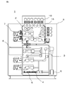
- FIG. 1 shows a usage example of a busbar connecting device, and shows a side sectional view of a switchgear to which the busbar connecting device is applied as an example.
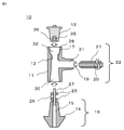
- 2 to 4 show the structure of the busbar connecting device shown in the first embodiment, FIG. 2 shows a state in which the parts are disassembled, and FIG. 3 shows a state in which the work hole portion is enlarged.
- FIG. 4 shows the assembled state, and the arrow on the right side of FIG. 4 schematically shows the pressure between the surfaces of the insulating bus connector and the insulating plug and between the insulating bus connector and the bushing.
- FIG. 1 shows a side sectional view of a switchgear 1 using a busbar connecting device 10.
- the left side of FIG. 1 is the front surface of the switchgear 1 and shows the surface on which the operating device is arranged.
- a disconnector 2 and its operating mechanism 7 In the housing 9 of the switch gear 1, a disconnector 2 and its operating mechanism 7, a vacuum circuit breaker 3 and its electromagnetic operating mechanism 8, a grounding switch 4, a lightning arrester 5, and a current transformer 6 are arranged.
- Busbar connecting devices 10 are arranged on the upper surface and the back surface of the switchgear 1.
- three systems of three-phase busbars are used, and a bushing 16 is used in a housing accommodating the disconnector 2. Installed.
- Each busbar connecting device 10 is arranged by connecting a busbar to the adjacent switchgear 1 on the front side or the back side of the paper surface of FIG.
- FIG. 2 is a cross-sectional view showing the structure of the busbar connecting device used in the present embodiment by disassembling it into main parts.
- the insulating plug 12, the insulating busbar connector 11, the bushing 16 and the solid insulating busbar 22 are shown in FIG. It can be roughly divided into two.
- the arrow 19 described between each indicates the insertion direction into the insulated bus connector 11 when assembling each component.
- the busbar connecting device 10 shown here is the busbar connecting device 10 connected to the terminal of the solid insulated busbar 22, and the insulated busbar connector 11 has only one busbar mounting hole 31.
- the busbar connecting device 10 for continuously connecting the solid insulated busbars 22 can be used.
- the insulating plug 12 shown in the upper part of the drawing has a metal portion 36 on the lower surface, and this metal portion 36 has an engagement hole 35 for engaging with the stud bolt 27 in the assembly process. Has been formed.
- the tip of the stud bolt 27 and the engagement hole 35 are threaded, and the stud bolt 27 is inserted into the engagement hole 35 in the step of inserting the insulating plug 12. By rotating, it can be inserted deeper along the screw.
- the bus bar conductor 20 is exposed at the left and right ends.
- a central portion other than the end portions is covered with an insulating shield 21 made of resin to prevent a short circuit or the like.
- a bushing 16 is shown at the bottom of FIG.
- a metal conducting conductor 15 is arranged in the center of the bushing 16, and the periphery of the conducting conductor 15 is covered with a resin bushing mold 14.
- a stud bolt 27 is attached to the current-carrying conductor 15, and a split terminal 25 for pressing and holding the end of the busbar conductor 20 from above and below and a contact conductor 26 for holding the busbar conductor 20 from the side surface are attached. There is.
- the insulating busbar connector 11 described in the center has a bushing mounting hole 30 on the lower surface, a busbar mounting hole 31 for mounting the solid insulating busbar 22 on the right side, and a work for fixing the busbar conductor 20 to the stud bolt 27 on the upper surface.
- a working hole 32 for inserting the insulating plug 12 after that is formed.
- the bushing mounting hole 30 Corresponding to the shape of the portion of the bushing 16 to be inserted into the insulating busbar connector 11 is frustoconical, the bushing mounting hole 30 also has a frustoconical shape with the depth gradually decreasing.
- the insulating plug 12 to be inserted into the working hole 32 has a truncated cone shape like the bushing 16.
- the working hole 32 is basically of a truncated cone shape that is gradually tapered downward at a certain rate in accordance with the insulating plug 12 to be inserted. is there.
- FIG. 3 shows an enlarged view of the work hole 32 and the insulating plug 12.
- the shape shown by the broken line 38 shows a general frustoconical working hole 32 corresponding to the frustoconical insulating plug 12.
- the work hole 32 of the present embodiment has a frusto-conical shape as a basic shape like the conventional general work hole 32, and gradually becomes thinner as the work hole 32 progresses from the shallow portion to the deep portion. ..
- the diameter of the opening 17 is added, and the insulation is It is larger than the diameter of a general working hole 32 corresponding to the plug 12.
- the work hole 32 when compared with a general frustoconical work hole 32 in the deep part of the work hole 32, the work hole 32 has a protrusion 13 opposite to the opening 17, and has a diameter larger than that of the work hole 32 corresponding to the insulating plug 12. Is getting smaller.
- the diameter is large in the shallow portion near the outside of the work hole 32 and conversely in the deep portion as compared with the conventional general work hole 32.
- ⁇ Assembling the busbar connecting device> 2 and 3 show a state in which the respective parts are separated in order to explain the structure of the busbar connecting device 10, and FIG. 4 shows a state after assembly. The outline of the assembling procedure will be described with reference to FIGS.
- the bushing 16 and the solid insulating busbar 22 are inserted into the bushing mounting hole 30 and the busbar mounting hole 31 of the insulating busbar connector 11, respectively.
- the current-carrying conductor 15 of the bushing 16 and the busbar conductor 20 of the solid insulating busbar 22 form a connecting portion as follows.
- the two split terminals 25 and the contact conductors 26 are attached to the stud bolts 27 inserted into the current-carrying conductors 15 of the bushing 16, and the busbar conductor 20 of the solid insulating busbar 22 is sandwiched between the split terminals 25 from above and below as shown in FIG. Then, the contact conductors 26 are sandwiched and fixed from the back surface. This connection work is performed from the work hole 32 provided in the insulated bus connector 11.
- the working hole 32 of the insulated bus connector 11 of the present embodiment As shown in FIG. 3, an opening 17 is formed in a shallow portion near the outside and a protrusion 13 is formed in a deep portion. Therefore, the working hole 32 of the present embodiment has a large diameter in the shallow portion near the outside and a small diameter in the deep portion, as compared with the case of a general frustoconical shape. Therefore, when the insulating plug 12 is inserted into the working hole 32, it can be very easily advanced by inserting it into the hole having a large diameter at the beginning of the inserting step. As shown in FIG.
- the surface pressure increases, and the surface pressure between the outer peripheral surface of the insulating plug 12 and the inner peripheral surface of the working hole 32 is In the shallow part near the outside, the diameter is large and low, and in the deep part, the diameter is small and high.
- the distribution of the surface pressure between the outer peripheral surface of the insulating plug 12 and the inner peripheral surface of the working hole 32 will be described in more detail with reference to FIG.
- the length of the plurality of arrows 39 shown on the right side of the cross-sectional view of the busbar connecting device of FIG. 4 is such that the magnitude of the surface pressure between the outer peripheral surface of the insulating plug 12 and the inner peripheral surface of the working hole 32 is simulated.
- the vertical alignment of the arrows 39 indicates the position within the busbar connecting device 10.
- a group of arrows 44 described on the lower side shows the surface pressure distribution when the bushing 16 is attached to the bushing attachment hole 30.
- all the arrows 44 have the same length, and indicate that the entire surface has the same surface pressure. That is, since the bushing attachment hole 30 is a truncated cone type similar to the truncated cone type bushing 16, the surface pressure does not have an in-plane distribution.
- a group of arrows 45 described on the upper side shows the surface pressure distribution when the insulating plug 12 is inserted into the working hole 32. That is, since the opening 17 is formed in the shallow portion near the outside of the work hole 32 and the work hole 32 is large, the surface pressure becomes lower than that in the case of the general frustoconical work hole 32. At the deep portion, the work hole 32 is made smaller by the protrusion 13, so that the surface pressure is higher.
- an air layer 37 is formed in the central portion of the insulating bus connector 11 as shown in FIG.
- the internal pressure of the air layer 37 increases as the insertion of the insulating plug 12 progresses.
- the diameter of the work hole 32 can be reduced uniformly without distinguishing the shallow portion and the deep portion close to the outside, so that the inner peripheral surface of the work hole 32 and the insulating plug
- the surface pressure with the outer peripheral surface of 12 can be increased, and as described in the present embodiment, the interface between the working hole 32 and the insulating plug 12 does not contain air, so that discharge can be prevented.
- the busbar connecting device 10 shown in the present embodiment it is possible to increase the surface pressure in the deep portion of the work hole 32 and prevent discharge, and at the same time, open the shallow hole near the outside of the work hole 32. 17 can be formed to increase the diameter of the working hole 32 and lower the surface pressure than usual. Therefore, the force for inserting the insulating plug 12 into the working hole 32 does not exceed that in the case where the working hole 32 has a general frustoconical shape, and does not cause a problem in the assembly process of the busbar connecting device 10.
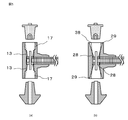
- Embodiment 2 The busbar connecting device 10 of the present embodiment will be described mainly with reference to FIG.
- the basic configuration of the busbar connecting device 10 is the same as that of the first embodiment, and the shape of the bushing mounting hole 30 is different in the present embodiment.
- FIG. 5A is a cross-sectional view of the busbar connecting device 10 according to the present embodiment, showing the structure and shape of the upper insulating plug 12 and the working hole 32 as compared with a general frustoconical type. Similar to the first embodiment, an opening 17 is provided at a shallow portion close to, and a projecting portion 13 is provided at a deep portion, and a step is provided on the way. Further, as a result, the surface pressure in the deep portion of the working hole 32 becomes high, so that it is difficult to contain air, it is possible to prevent electric discharge and the like, and the surface pressure in the shallow portion near the outside is not low. This is also the same as the first embodiment in that no problem occurs.
- the relationship between the working hole 32 and the insulating plug 12 is applied to the relationship between the bushing mounting hole 30 of the insulating busbar connector 11 and the bushing 16 so that the bushing mounting hole 30 has a shallow portion near the outside.
- the opening 17 is provided with the protrusion 13 in the deep portion.
- Embodiment 3 The busbar connecting device 10 of the present embodiment will be described mainly with reference to FIG.
- the basic configuration of the busbar connecting device 10 is the same as in the first and second embodiments.
- the opening 17 and the bushing attachment hole 30 formed inside the working hole 32 and The shape of the projecting portion 13 is not stepwise as shown in FIG. 5A, etc., but the size of the working hole 32 and the bushing mounting hole changes gently from the opening 29 to the projecting portion 28. ing.
- FIG. 5B is a cross-sectional view of the busbar connecting device 10 according to the present embodiment, in which the working hole 32 and the bushing mounting hole 30 have a hole size deeper than that of a general frustoconical type. Similar to the second embodiment, the protrusion 28 is made smaller and the opening 29 is provided at a shallow portion near the outside.
- a broken line 38 shows a sectional shape of a general frustoconical work hole 32 and a bushing mounting hole 30.
- the size of the diameter of the working hole 32 and the bushing mounting hole 30 is smaller in the deep portion than in the case of a general truncated cone type, It is enlarged in the shallow part near the outside. That is, it can be said that the inclination angle of the side surface of the truncated cone is reduced.
- a high surface pressure can be achieved at a deep portion at any interface between the working hole 32 and the insulating plug 12 and between the bushing attachment hole 30 and the bushing 16, and the interface does not contain air. Therefore, no discharge occurs even in the high voltage part. Further, the surface pressure can be reduced in the shallow portion near the outside of the working hole 32 and the bushing mounting hole 30, and there is no problem in workability. As described above, in the present embodiment, it is possible to obtain a good busbar connecting device 10 having excellent workability and reliability.
- FIG. 6 shows a state in which the busbar connecting device 10 is assembled and attached to the housing 9 via the bushing 16.
- the present embodiment differs from Embodiment 1 in that a hollow bus bar 41 having a hollow portion 40 at the center of solid insulation bus bar 22 is used.
- the volume of the air layer 37 can be increased, and the pressure increase of the air layer 37 when the insulating plug 12 is inserted into the working hole 32 can be reduced. Therefore, it is possible to prevent air from entering the interface between the insulating plug 12 and the working hole 32 and the bushing 16 and the bushing mounting hole 30.
- the busbar connecting device 10 of the present embodiment prevents electric discharge by preventing air from entering the interface between the insulating plug 12 and the working hole 32 and the bushing 16 and the bushing mounting hole 30. It is possible to obtain the busbar connecting device 10 which is excellent in workability and reliability without causing a problem in the workability.
Landscapes
- Engineering & Computer Science (AREA)
- Power Engineering (AREA)
- Patch Boards (AREA)
- Installation Of Bus-Bars (AREA)
Abstract
L'invention concerne un dispositif de connexion de barre omnibus (10) qui peut simultanément permettre une excellente aptitude au façonnage et une fiabilité élevée. Le dispositif de connexion de barre omnibus est caractérisé en ce qu'il comprend : une section de connexion à laquelle sont connectés un conducteur de barre omnibus (20) et un corps électroconducteur (15) d'une douille (16); un connecteur de barre omnibus isolant (11) qui recouvre la section de connexion ; un trou de travail (32) qui permet la communication depuis l'extérieur du connecteur de barre omnibus isolant (11) jusqu'à la section de connexion ; et une fiche isolante (12) qui est insérée dans le trou de travail (32) pour sceller le connecteur de barre omnibus isolant. La pression de surface entre la surface périphérique interne du trou de travail (32) et la surface périphérique externe de la fiche isolante (12) est supérieure à une partie profonde qu'une partie peu profonde du trou de travail (32).
Priority Applications (5)
| Application Number | Priority Date | Filing Date | Title |
|---|---|---|---|
| EP18944515.8A EP3905460A4 (fr) | 2018-12-26 | 2018-12-26 | Dispositif de connexion des barre omnibus |
| JP2019525920A JP6563160B1 (ja) | 2018-12-26 | 2018-12-26 | 母線接続装置 |
| CN201880099871.XA CN113169529B (zh) | 2018-12-26 | 2018-12-26 | 母线连接装置 |
| PCT/JP2018/047718 WO2020136737A1 (fr) | 2018-12-26 | 2018-12-26 | Dispositif de connexion des barre omnibus |
| US17/293,497 US11658467B2 (en) | 2018-12-26 | 2018-12-26 | Busbar connecting device |
Applications Claiming Priority (1)
| Application Number | Priority Date | Filing Date | Title |
|---|---|---|---|
| PCT/JP2018/047718 WO2020136737A1 (fr) | 2018-12-26 | 2018-12-26 | Dispositif de connexion des barre omnibus |
Publications (1)
| Publication Number | Publication Date |
|---|---|
| WO2020136737A1 true WO2020136737A1 (fr) | 2020-07-02 |
Family
ID=67695607
Family Applications (1)
| Application Number | Title | Priority Date | Filing Date |
|---|---|---|---|
| PCT/JP2018/047718 Ceased WO2020136737A1 (fr) | 2018-12-26 | 2018-12-26 | Dispositif de connexion des barre omnibus |
Country Status (5)
| Country | Link |
|---|---|
| US (1) | US11658467B2 (fr) |
| EP (1) | EP3905460A4 (fr) |
| JP (1) | JP6563160B1 (fr) |
| CN (1) | CN113169529B (fr) |
| WO (1) | WO2020136737A1 (fr) |
Families Citing this family (4)
| Publication number | Priority date | Publication date | Assignee | Title |
|---|---|---|---|---|
| US11056862B2 (en) * | 2017-06-20 | 2021-07-06 | Mitsubishi Electric Corporation | Electrical device connector and switchgear |
| EP4160835A4 (fr) * | 2020-05-29 | 2023-07-19 | Mitsubishi Electric Corporation | Dispositif de connexion par bus |
| DE112020007460T5 (de) * | 2020-07-27 | 2023-05-17 | Mitsubishi Electric Corporation | Sammelschienen-verbindungsvorrichtung |
| CN116613569B (zh) * | 2023-04-25 | 2025-05-06 | 东莞市江涵电子有限公司 | 一种光伏使用多通道横向组合连接器 |
Citations (6)
| Publication number | Priority date | Publication date | Assignee | Title |
|---|---|---|---|---|
| JPS54145988A (en) * | 1978-05-09 | 1979-11-14 | Mitsubishi Electric Corp | Bus connection apparatus for enclosed switchboard |
| JPH0556541A (ja) | 1991-06-28 | 1993-03-05 | Fuji Electric Co Ltd | 絶縁母線の接続器具 |
| JPH09261836A (ja) * | 1996-03-18 | 1997-10-03 | Inoue Seisakusho:Kk | 機器直結形ケーブル接続部 |
| JP2003016881A (ja) * | 2001-07-05 | 2003-01-17 | Toshiba Corp | 電気機器の接続装置 |
| JP2014033562A (ja) * | 2012-08-06 | 2014-02-20 | Mitsubishi Electric Corp | ケーブル接続装置 |
| WO2016189956A1 (fr) * | 2015-05-26 | 2016-12-01 | 三菱電機株式会社 | Dispositif à semiconducteur et procédé de fabrication de dispositif à semiconducteur |
Family Cites Families (34)
| Publication number | Priority date | Publication date | Assignee | Title |
|---|---|---|---|---|
| US3747048A (en) * | 1971-08-19 | 1973-07-17 | Amp Inc | High voltage connector |
| DE3722955A1 (de) | 1987-07-09 | 1989-01-19 | Siemens Ag | Steckverbindung fuer ein geschirmtes starkstromkabel |
| JP2613404B2 (ja) * | 1987-11-24 | 1997-05-28 | 株式会社東芝 | 絶縁母線の接続方法 |
| DE19502048A1 (de) * | 1995-01-13 | 1996-07-18 | Siemens Ag | Anschlußvorrichtung für feststoffisolierte Leiter von Mittelspannungs-Schaltanlagen |
| JP2683788B2 (ja) * | 1995-01-30 | 1997-12-03 | 株式会社東芝 | ブッシングの取付部 |
| JP2683787B2 (ja) * | 1995-01-30 | 1997-12-03 | 株式会社東芝 | ケーブル終端接続部 |
| JP3078483B2 (ja) * | 1995-09-29 | 2000-08-21 | 昭和電線電纜株式会社 | ケーブル終端接続部 |
| JP3280264B2 (ja) * | 1997-03-04 | 2002-04-30 | 昭和電線電纜株式会社 | 絶縁ブッシング用ケーブル接続部 |
| CA2207287C (fr) * | 1997-06-09 | 2002-08-27 | Cabletel Communications Corp. | Connecteur de cable coaxial avec bague exterieure de pincement du cable |
| JP4313881B2 (ja) * | 1999-03-25 | 2009-08-12 | 昭和電線ケーブルシステム株式会社 | 絶縁母線接続構造 |
| JP4376400B2 (ja) * | 2000-01-20 | 2009-12-02 | 三菱電機株式会社 | 絶縁ガス封入閉鎖配電盤間の母線接続装置 |
| JP2002345131A (ja) * | 2001-05-15 | 2002-11-29 | Mitsubishi Electric Corp | ガス絶縁開閉装置用母線接続装置 |
| US6520795B1 (en) * | 2001-08-02 | 2003-02-18 | Hubbell Incorporated | Load reducing electrical device |
| CN100448125C (zh) * | 2002-11-22 | 2008-12-31 | 三菱电机株式会社 | 开闭装置的设备的连接装置 |
| US7568927B2 (en) | 2007-04-23 | 2009-08-04 | Cooper Technologies Company | Separable insulated connector system |
| CN101340035B (zh) * | 2007-07-02 | 2010-08-25 | 3M创新有限公司 | 适配器、具有该适配器的电缆连接器和电缆连接器组件 |
| DE102007063478A1 (de) * | 2007-12-20 | 2009-02-19 | Siemens Ag | Anordnung mit einer Sammelschiene |
| CN201413951Y (zh) * | 2009-03-04 | 2010-02-24 | 宁波电业局 | 碳纤维复合芯导线芯卡 |
| FR2953977B1 (fr) * | 2009-12-14 | 2012-05-04 | Schneider Electric Ind Sas | Dispositif de raccordement electrique d'une barre appartenant a un jeu de barres a une traversee electrique appartenant a l'enveloppe isolante d'un appareil electrique de coupure |
| JP5761108B2 (ja) * | 2012-04-06 | 2015-08-12 | 日立金属株式会社 | 固体絶縁母線の終端接続部 |
| CN102683911A (zh) * | 2012-05-19 | 2012-09-19 | 林锐涛 | 管母线锥形紧压器 |
| US9124050B2 (en) * | 2012-07-19 | 2015-09-01 | Thomas & Betts International Llc | Electrical connector having grounding mechanism |
| US9350103B2 (en) * | 2012-07-19 | 2016-05-24 | Thomas & Betts International, Llc | Electrical connector having grounding mechanism |
| US9112322B2 (en) * | 2012-08-27 | 2015-08-18 | Thomas & Betts International, Llc | Electrical connector with multiple interfaces |
| CN203552917U (zh) * | 2013-11-26 | 2014-04-16 | 江苏科兴电器有限公司 | 一种固体绝缘环网柜用电流互感器 |
| CN203757255U (zh) * | 2013-12-31 | 2014-08-06 | 重庆前卫海洋石油工程设备有限责任公司 | 深水多回路快速连接母接头 |
| DE102014105179A1 (de) * | 2014-04-11 | 2015-10-15 | Schneider Electric Industries Sas | Verfahren zum Betreiben einer Schaltanlage |
| JP2015204260A (ja) * | 2014-04-16 | 2015-11-16 | 矢崎総業株式会社 | ゴム栓固定構造 |
| CN205304199U (zh) * | 2015-12-28 | 2016-06-08 | 浠水深博电气有限公司 | 一种冷缩可分离式电缆终端 |
| CN206116121U (zh) * | 2016-08-28 | 2017-04-19 | 威腾电气集团股份有限公司 | 一种管型母线接头绝缘结构 |
| US11056862B2 (en) * | 2017-06-20 | 2021-07-06 | Mitsubishi Electric Corporation | Electrical device connector and switchgear |
| CN207052945U (zh) * | 2017-09-21 | 2018-02-27 | 深圳市惠程电气股份有限公司 | 一种t形连接器、十字形连接器、母线和并柜母线系统 |
| CN114026754B (zh) * | 2019-06-27 | 2024-07-19 | 三菱电机株式会社 | 排气工具以及使用排气工具的开关装置的制造方法 |
| DE112020007460T5 (de) * | 2020-07-27 | 2023-05-17 | Mitsubishi Electric Corporation | Sammelschienen-verbindungsvorrichtung |
-
2018
- 2018-12-26 WO PCT/JP2018/047718 patent/WO2020136737A1/fr not_active Ceased
- 2018-12-26 JP JP2019525920A patent/JP6563160B1/ja active Active
- 2018-12-26 CN CN201880099871.XA patent/CN113169529B/zh active Active
- 2018-12-26 EP EP18944515.8A patent/EP3905460A4/fr active Pending
- 2018-12-26 US US17/293,497 patent/US11658467B2/en active Active
Patent Citations (6)
| Publication number | Priority date | Publication date | Assignee | Title |
|---|---|---|---|---|
| JPS54145988A (en) * | 1978-05-09 | 1979-11-14 | Mitsubishi Electric Corp | Bus connection apparatus for enclosed switchboard |
| JPH0556541A (ja) | 1991-06-28 | 1993-03-05 | Fuji Electric Co Ltd | 絶縁母線の接続器具 |
| JPH09261836A (ja) * | 1996-03-18 | 1997-10-03 | Inoue Seisakusho:Kk | 機器直結形ケーブル接続部 |
| JP2003016881A (ja) * | 2001-07-05 | 2003-01-17 | Toshiba Corp | 電気機器の接続装置 |
| JP2014033562A (ja) * | 2012-08-06 | 2014-02-20 | Mitsubishi Electric Corp | ケーブル接続装置 |
| WO2016189956A1 (fr) * | 2015-05-26 | 2016-12-01 | 三菱電機株式会社 | Dispositif à semiconducteur et procédé de fabrication de dispositif à semiconducteur |
Non-Patent Citations (1)
| Title |
|---|
| See also references of EP3905460A4 |
Also Published As
| Publication number | Publication date |
|---|---|
| JP6563160B1 (ja) | 2019-08-21 |
| EP3905460A1 (fr) | 2021-11-03 |
| US11658467B2 (en) | 2023-05-23 |
| CN113169529B (zh) | 2023-04-11 |
| JPWO2020136737A1 (ja) | 2021-02-15 |
| EP3905460A4 (fr) | 2021-12-08 |
| CN113169529A (zh) | 2021-07-23 |
| US20220006270A1 (en) | 2022-01-06 |
Similar Documents
| Publication | Publication Date | Title |
|---|---|---|
| WO2020136737A1 (fr) | Dispositif de connexion des barre omnibus | |
| US3376541A (en) | Safe break terminator | |
| US11201437B2 (en) | Insulating connector for an electrical cable | |
| KR102386790B1 (ko) | 절연 부싱을 포함한 고전류 커넥터 | |
| EP2806510B1 (fr) | Matériau diélectrique gélatineux pour connecteur haute tension | |
| CN106663507B (zh) | 电连接器 | |
| CN105529663B (zh) | 母线组件及使用该母线组件的气体绝缘金属封闭开关设备 | |
| JP2009022115A (ja) | 固体絶縁スイッチギヤおよびその試験方法 | |
| CN210607856U (zh) | 通讯用接插件 | |
| KR20180121399A (ko) | 변압기 저압부싱 어셈블리 | |
| CN108711690B (zh) | 一种印制板连接器 | |
| JP4690378B2 (ja) | コネクタ | |
| JP5337770B2 (ja) | 電力ケーブル接続部 | |
| US20240162667A1 (en) | Electronics jack | |
| HK40050175B (en) | Busbar connecting device | |
| HK40050175A (en) | Busbar connecting device | |
| CN116134687A (zh) | 母线连接装置 | |
| EP3499537B1 (fr) | Système de fixation à utiliser pour la commutation de pôles à tension moyenne ou élevée | |
| JP5548567B2 (ja) | エポキシブッシング | |
| CN219226755U (zh) | 可分离连接器及具有其的开关设备 | |
| JP5191474B2 (ja) | ブッシング及びブッシングの接続部 | |
| KR20140005965U (ko) | 초고압 기기용 컨덕터 결합구조 | |
| KR20260016514A (ko) | 커넥터용 피팅 요소 | |
| JP5238016B2 (ja) | 接続母線 | |
| CN118712817A (zh) | 一种可分离式电缆连接器 |
Legal Events
| Date | Code | Title | Description |
|---|---|---|---|
| ENP | Entry into the national phase |
Ref document number: 2019525920 Country of ref document: JP Kind code of ref document: A |
|
| 121 | Ep: the epo has been informed by wipo that ep was designated in this application |
Ref document number: 18944515 Country of ref document: EP Kind code of ref document: A1 |
|
| NENP | Non-entry into the national phase |
Ref country code: DE |
|
| ENP | Entry into the national phase |
Ref document number: 2018944515 Country of ref document: EP Effective date: 20210726 |