WO2020137036A1 - Transducteur électrostatique et son procédé de fabrication - Google Patents
Transducteur électrostatique et son procédé de fabrication Download PDFInfo
- Publication number
- WO2020137036A1 WO2020137036A1 PCT/JP2019/036661 JP2019036661W WO2020137036A1 WO 2020137036 A1 WO2020137036 A1 WO 2020137036A1 JP 2019036661 W JP2019036661 W JP 2019036661W WO 2020137036 A1 WO2020137036 A1 WO 2020137036A1
- Authority
- WO
- WIPO (PCT)
- Prior art keywords
- insulating layer
- electrode
- layer
- electrode sheet
- heater
- Prior art date
- Legal status (The legal status is an assumption and is not a legal conclusion. Google has not performed a legal analysis and makes no representation as to the accuracy of the status listed.)
- Ceased
Links
Images


Classifications
-
- H—ELECTRICITY
- H05—ELECTRIC TECHNIQUES NOT OTHERWISE PROVIDED FOR
- H05B—ELECTRIC HEATING; ELECTRIC LIGHT SOURCES NOT OTHERWISE PROVIDED FOR; CIRCUIT ARRANGEMENTS FOR ELECTRIC LIGHT SOURCES, IN GENERAL
- H05B3/00—Ohmic-resistance heating
- H05B3/20—Heating elements having extended surface area substantially in a two-dimensional [2D] plane, e.g. plate-heater
- H05B3/22—Heating elements having extended surface area substantially in a two-dimensional [2D] plane, e.g. plate-heater non-flexible
- H05B3/28—Heating elements having extended surface area substantially in a two-dimensional [2D] plane, e.g. plate-heater non-flexible heating conductor embedded in insulating material
- H05B3/286—Heating elements having extended surface area substantially in a two-dimensional [2D] plane, e.g. plate-heater non-flexible heating conductor embedded in insulating material the insulating material being an organic material, e.g. plastic
-
- H—ELECTRICITY
- H05—ELECTRIC TECHNIQUES NOT OTHERWISE PROVIDED FOR
- H05B—ELECTRIC HEATING; ELECTRIC LIGHT SOURCES NOT OTHERWISE PROVIDED FOR; CIRCUIT ARRANGEMENTS FOR ELECTRIC LIGHT SOURCES, IN GENERAL
- H05B3/00—Ohmic-resistance heating
- H05B3/10—Heating elements characterised by the composition or nature of the materials or by the arrangement of the conductor
- H05B3/12—Heating elements characterised by the composition or nature of the materials or by the arrangement of the conductor characterised by the composition or nature of the conductive material
- H05B3/14—Heating elements characterised by the composition or nature of the materials or by the arrangement of the conductor characterised by the composition or nature of the conductive material the material being non-metallic
- H05B3/141—Conductive ceramics, e.g. metal oxides, metal carbides, barium titanate, ferrites, zirconia, vitrous compounds
-
- H—ELECTRICITY
- H05—ELECTRIC TECHNIQUES NOT OTHERWISE PROVIDED FOR
- H05B—ELECTRIC HEATING; ELECTRIC LIGHT SOURCES NOT OTHERWISE PROVIDED FOR; CIRCUIT ARRANGEMENTS FOR ELECTRIC LIGHT SOURCES, IN GENERAL
- H05B3/00—Ohmic-resistance heating
- H05B3/20—Heating elements having extended surface area substantially in a two-dimensional [2D] plane, e.g. plate-heater
- H05B3/34—Heating elements having extended surface area substantially in a two-dimensional [2D] plane, e.g. plate-heater flexible, e.g. heating nets or webs
- H05B3/36—Heating elements having extended surface area substantially in a two-dimensional [2D] plane, e.g. plate-heater flexible, e.g. heating nets or webs heating conductor embedded in insulating material
-
- H—ELECTRICITY
- H05—ELECTRIC TECHNIQUES NOT OTHERWISE PROVIDED FOR
- H05B—ELECTRIC HEATING; ELECTRIC LIGHT SOURCES NOT OTHERWISE PROVIDED FOR; CIRCUIT ARRANGEMENTS FOR ELECTRIC LIGHT SOURCES, IN GENERAL
- H05B2203/00—Aspects relating to Ohmic resistive heating covered by group H05B3/00
- H05B2203/017—Manufacturing methods or apparatus for heaters
Definitions
- the present invention relates to an electrostatic transducer and a method for manufacturing the same.
- Patent Documents 1 and 2 describe a steering wheel including an electrostatic sensor that detects that the driver's hand is released and a heater.
- the steering wheel described in Patent Document 1 is manufactured by winding a heater wire in a coil shape on the outer peripheral side of the axis of the steering wheel and disposing an electrostatic sensor on the outer peripheral side of the heater wire.
- a manufacturing method in which a heater wire is attached to a base material such as the axis of a steering wheel and then an electrostatic sheet is attached requires a great number of manufacturing steps. That is, a heater wire attaching step and an electrostatic sheet attaching step are required. Further, when the base material mounting surface on which the heater wire and the electrostatic sheet are mounted is a curved surface such as the axis of a steering wheel, and has a complicated shape rather than a simple plane, the above two steps are included. Therefore, a large number of manufacturing steps are required. Therefore, it is required to reduce the number of manufacturing steps.
- the transducer when the transducer includes a flexible base material, a heater attached to the base material, and an electrostatic sensor, it is required to reduce the number of manufacturing steps. Further, even when the transducer is configured to include the heater and the electrostatic sensor without including the base material, it is required to reduce the number of manufacturing steps.
- VOC volatile organic compounds
- An object of the present invention is to provide an electrostatic transducer having a heater function, which can be manufactured without using a volatile adhesive and an organic solvent, and which can reduce the number of manufacturing steps, and a manufacturing method thereof.
- An electrostatic transducer having a heater function includes an electrode sheet, a heater formed in a sheet shape and arranged to face the electrode sheet, the electrode sheet formed in a sheet shape, and the heater.
- An insulating layer sandwiched between and, which is formed of a fusion material, is configured as a part of at least one of the electrode sheet and the insulating layer or joined to the electrode sheet and the insulating layer as a separate member, An electrode fusion layer that joins the electrode sheet and the insulating layer by fusion of itself is provided.
- each of the above-mentioned constituent members of the electrostatic transducer having the heater function is formed in a sheet shape
- the electrode sheet, the insulating layer and the heater which form the electrostatic transducer are integrally formed in a sheet shape as a whole. .. Therefore, it is possible to reduce the number of manufacturing steps of the electrostatic transducer regardless of whether the electrostatic transducer includes the base material or not.
- the mounting step on the mounting surface is not required. It can be one step. Therefore, the number of manufacturing steps can be reduced. Further, since the mounting step can be performed in one step with respect to the mounting surface, the more complicated the mounting surface is, the more effective the manufacturing process can be reduced. The number of manufacturing steps can be reduced also when the above-mentioned constituent members of the electrostatic transducer are attached to a flexible base material.
- a method of manufacturing an electrostatic transducer having a heater function according to the present invention manufactures the electrostatic transducer by heating and pressing a laminated body including at least the electrode sheet, the insulating layer, and the heater. To do. That is, the electrode sheet and the insulating layer are joined by a fusion material that is fused by heating and pressurization. Therefore, an electrostatic transducer having a heater function can be manufactured without using a volatile adhesive and an organic solvent. That is, it is possible to manufacture an environment-friendly electrostatic transducer.
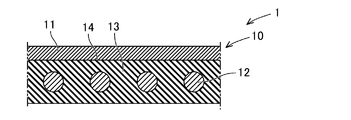
- FIG. 3 is a cross-sectional view of the basic configuration of the transducer 1.
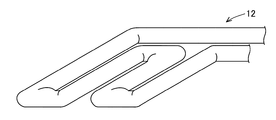
- FIG. It is a perspective view showing the heater 12.
- the electrostatic transducer (hereinafter referred to as “transducer”) includes an electrostatic sheet having a heater function.
- the transducer includes, for example, a base material and the electrostatic sheet attached to the attachment surface of the base material.
- the base material is an arbitrary member and is made of metal, resin, or other material.
- the mounting surface of the base material may be formed into a three-dimensional shape such as a curved surface, a composite flat surface (a shape formed by a plurality of flat surfaces), or a composite shape of a flat surface and a curved surface. You may form in planar shape.
- the electrostatic sheet can be attached to the attachment surface of the base material.
- the transducer can be used as the electrostatic sheet alone without the base material.
- the electrostatic sheet is placed on the mounting surface (front surface) of the base material.
- the electrostatic sheet as a whole is flexible. Flexible means having flexibility and being stretchable in the plane direction. Therefore, even if the mounting surface of the base material has a three-dimensional shape, the electrostatic sheet can be mounted along the mounting surface of the base material. In particular, wrinkling of the electrostatic sheet can be suppressed by mounting the electrostatic sheet on the mounting surface of the base material while stretching the electrostatic sheet in the surface direction.
- the electrostatic sheet can function as an actuator or a sensor by utilizing the change in electrostatic capacitance between a pair of electrodes.
- the electrostatic sheet may include at least one of the pair of electrodes, and is not limited to the configuration including the pair of electrodes. Of course, the electrostatic sheet may include a pair of electrodes.
- the electrostatic sheet can function as an actuator that generates vibration, sound, etc. by utilizing the change in electrostatic capacitance between the electrodes. Further, the electrostatic sheet can function as a sensor that detects a pushing force or the like from the outside or a sensor that detects contact or approach of a conductor having a potential by utilizing a change in capacitance between the electrodes. ..
- the electrostatic sheet functions as an actuator, when a voltage is applied to the electrodes, the dielectric body is deformed according to the potential between the electrodes, and the deformation of the dielectric body causes vibration.
- the electrostatic sheet functions as a sensor that detects the pressing force, the dielectric is deformed due to the input of external pressing force, vibration, sound, etc. (hereinafter, external pressing force, etc.).
- external pressing force etc.
- the electrostatic capacitance between the electrodes changes, and by detecting the voltage corresponding to the electrostatic capacitance between the electrodes, the pushing force or the like from the outside is detected.
- the electrostatic sheet functions as a sensor that detects contact or approach
- the capacitance between the electrodes changes due to the contact or approach of a conductor having a potential, and the changed capacitance between the electrodes is detected.
- the contact or approach of the conductor is detected by detecting the corresponding voltage.
- the transducer can be applied to, for example, the surface of a pointing device such as a mouse or joystick, or the surface of a vehicle part.
- vehicle parts include a steering wheel, a door knob, a shift lever, an armrest, a door trim, a center trim and a center console.
- the base material is formed of a non-flexible material such as metal or resin. That is, the transducer can apply heat to the target person in addition to detecting the state (operation, etc.) of the target person and applying vibration to the target person.
- the transducer may be arranged on the surface layer side of the seat seat surface or the surface layer side of the backrest surface.
- the transducer may be configured such that an electrostatic sheet having a heater function is attached to a base material formed of a flexible material such as a resin film.
- the transducer may be configured by an electrostatic sheet having a heater function without including the base material.
- the transducer 1 includes an electrostatic sheet 10 having a heater function, as shown in FIG.
- the electrostatic sheet 10 is formed in a sheet shape as a whole and is flexible.
- the term “flexible” means that it has flexibility and can be stretched in the plane direction.
- the electrostatic sheet 10 is attached to the attachment surface of the above-mentioned base material (not shown in FIG. 1). As shown in FIG. 1, the electrostatic sheet 10 includes at least an electrode sheet 11, a heater 12, and an insulating layer 13. The electrostatic sheet 10 may have a configuration other than the electrode sheet 11, the heater 12, and the insulating layer 13.
- the electrode sheet 11 has conductivity. Furthermore, the electrode sheet 11 is flexible.
- the electrode sheet 11 is formed of, for example, a conductive elastomer, a conductive cloth, a metal foil, or the like.
- the electrode sheet 11 is made of a conductive elastomer
- the electrode sheet 11 is formed of an elastomer containing a conductive filler. That is, the electrode sheet 11 is formed by using an elastomer as a base material and containing a conductive filler.
- the electrode sheet 11 is made of, for example, a thermoplastic elastomer.
- the electrode sheet 11 may be formed of the thermoplastic elastomer itself, or may be formed of an elastomer crosslinked by heating the thermoplastic elastomer as a raw material.
- the electrode sheet 11 can be selected from one or more of styrene-based, olefin-based, vinyl chloride-based, urethane-based, ester-based, amide-based, and other elastomers.
- examples of the styrene elastomer include SBS, SEBS, SEPS and the like.
- examples of the olefin elastomer include EEA, EMA, EMMA and the like, as well as a copolymer of ethylene and ⁇ -olefin (ethylene-octene copolymer) and the like.
- the electrode sheet 11 may contain rubber or resin other than the thermoplastic elastomer.
- rubber such as ethylene-propylene rubber (EPM, EPDM)
- EPM ethylene-propylene rubber
- the electrode sheet 11 may contain a flexibility-imparting component such as a plasticizer.
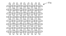
- the conductive cloth is a woven or non-woven fabric formed of conductive fibers.
- the conductive fiber is formed by coating the surface of the flexible fiber with a conductive material.
- the conductive fiber is formed, for example, by plating the surface of a resin fiber such as polyethylene with copper or nickel.
- the metal foil has a plurality of through holes similarly to the conductive cloth. Therefore, the electrode sheet 11 has flexibility and can be expanded in the surface direction as the through holes are deformed.
- the metal foil may be any conductive metal material, and for example, a copper foil, an aluminum foil or the like can be applied.
- the heater 12 is formed into a sheet shape (planar shape) by a heater wire.
- the heater 12 is arranged to face one surface of the electrode sheet 11.
- the heater wire is a metal alloy-based material, and for example, nickel chrome, iron chrome, or the like is applied.
- the insulating layer 13 is formed in a sheet shape and is sandwiched at least between the electrode sheet 11 and the heater 12.
- the insulating layer 13 may be formed so as to cover both surfaces (the upper and lower surfaces of FIG. 1) of the heater 12. Note that FIG. 1 illustrates the case where the insulating layer 13 covers both surfaces of the heater 12.
- the insulating layer 13 is made of a flexible material.
- the insulating layer 13 is formed of, for example, a thermoplastic material, particularly a thermoplastic elastomer. Further, the insulating layer 13 may be made of a non-thermoplastic elastomer foam material, a non-woven fabric, a woven fabric, or the like.
- the insulating layer 13 can also function as a dielectric layer in the electrostatic sheet 10.
- the electrostatic sheet 10 further includes an electrode fusion layer 14.
- the electrode fusion layer 14 is made of a fusion material.
- the electrode fusing layer 14 joins the electrode sheet 11 and the insulating layer 13 by fusing (thermal fusion) of the electrode fusing layer 14 itself.
- the electrode fusing layer 14 may be configured as a part of the electrode sheet 11 or may be configured as a part of the insulating layer 13.
- the electrode fusing layer 14 may be formed as a part of the electrode sheet 11 and also as a part of the insulating layer 13.
- the electrode fusion bonding layer 14 may be joined to the electrode sheet 11 and the insulating layer 13 as a separate member.
- a method of manufacturing the above-described basic configuration of the transducer 1 will be described.
- a laminated body in which the electrode sheet 11, the insulating layer 13, and the heater 12 are laminated in this order, which are components of the electrostatic sheet 10, is prepared (preparation step).
- the insulating layer 13 may be formed integrally with the heater 12 in advance, or may be formed separately from the electrode sheet 11 and the heater 12.
- the laminate is heated and pressed (heating and pressing step). Then, the electrode fusion layer 14 joins the electrode sheet 11 and the insulating layer 13. As described above, the electrode fusing layer 14 is a part of the electrode sheet 11, a part of the insulating layer 13, or a material different from the electrode sheet 11 and the insulating layer 13. In this way, the electrostatic sheet 10 is manufactured. Then, the electrostatic sheet 10 is attached to a base material (not shown). When the substrate is not present, the transducer 1 is completed by manufacturing the electrostatic sheet 10.
- the electrostatic sheet 10 forming the transducer 1 is integrally formed in a sheet shape as a whole. Therefore, the number of manufacturing steps of the transducer 1 can be reduced regardless of whether the transducer 1 is provided with a base material or not.
- the constituent members 11, 12, and 13 of the transducer 1 are integrally formed, when the constituent members 11, 12, and 13 of the transducer 1 are mounted on the mounting surface of the base material, mounting on the mounting surface is performed.
- the process can be one process. Therefore, the number of manufacturing steps can be reduced.
- the mounting step can be performed in one step with respect to the mounting surface, the more complicated the mounting surface is, the more effective the manufacturing process can be reduced.
- the number of manufacturing steps can be reduced also when the constituent members 11, 12, and 13 of the transducer 1 are attached to a flexible base material.
- the bonding between the electrode sheet 11 and the insulating layer 13 is performed by a fusion material that can be softened by heat. Therefore, the electrostatic sheet 10 having a heater function can be manufactured without using the volatile adhesive and the organic solvent. That is, the environment-friendly transducer 1 can be manufactured.
- the electrode fusing layer 14 is composed of a part of the electrode sheet 11 or a part of the insulating layer 13, no special member is required as the electrode fusing layer 14. As a result, it is possible to further reduce the cost.
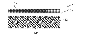
- the configuration of the electrostatic sheet 10a of the first example will be described with reference to FIGS. 3 and 4.
- the electrode sheet 11a that constitutes the electrostatic sheet 10a is formed by including a thermoplastic material.
- the electrode sheet 11a is made of a thermoplastic elastomer. That is, the electrode sheet 11a can be softened by heating and pressurizing and fused to the mating member.
- the insulating layer 13a is made of a thermoplastic material, for example, a thermoplastic elastomer.
- the thermoplastic material of the insulating layer 13a has a higher softening point than the thermoplastic material of the electrode sheet 11a.
- the insulating layer 13a has irregularities on the joint surface with the electrode sheet 11a. For example, by forming an uneven surface on a mold for molding the insulating layer 13a, it is possible to form unevenness on the bonding surface of the insulating layer 13a with the electrode sheet 11a.
- the electrostatic sheet 10a is manufactured by laminating the electrode sheet 11a and the insulating layer 13a and heating and pressing the laminated body.
- the electrode sheet 11a is formed of a thermoplastic material having a softening point lower than that of the insulating layer 13a. Therefore, when the laminated body is heated and pressed, the thermoplastic material of the electrode sheet 11a is first softened and enters the concave portion of the insulating layer 13a.
- a part of the electrode sheet 11a functions as an electrode fusion layer 14 that joins the electrode sheet 11a and the uneven surface of the insulating layer 13a by fusion of itself.
- a part of the electrode sheet 11a enters the concave portion of the insulating layer 13a, thereby exerting an anchor effect and increasing the bonding force between the electrode sheet 11a and the insulating layer 13a.
- the insulating layer 13a is made of a thermoplastic material, but a non-thermoplastic material may be applied. In this case, naturally, when the laminated body is heated and pressed, the thermoplastic material of the electrode sheet 11a is softened before the insulating layer 13a.
- the insulating layer 13a is a non-woven fabric or a woven fabric formed of fibers of a non-thermoplastic material. Since the non-woven fabric or the woven fabric is formed of fibers, at least the joint surface of the insulating layer 13a with the electrode sheet 11a has irregularities as shown in FIG. Specifically, the joint surface of the insulating layer 13a has fibers and irregularities formed by spaces between the fibers. That is, the insulating layer 13a has an uneven surface in which fibers are convex portions and concave portions are between adjacent fibers.
- the electrode sheet 11a and the insulating layer 13a are laminated, and the laminated body is heated and pressed to manufacture the electrostatic sheet 10a. That is, when the laminated body is heated and pressed, the thermoplastic material of the electrode sheet 11a is softened and enters the concave portion of the insulating layer 13a. And a part of electrode sheet 11a functions as electrode fusion layer 14 which joins electrode sheet 11a and the uneven surface of insulating layer 13a by fusion of itself.
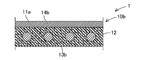
- Electrostatic sheet 10b of the fourth example The configuration of the electrostatic sheet 10b of the fourth example will be described with reference to FIGS.
- the electrode sheet 11a forming the electrostatic sheet 10b is formed by including a thermoplastic material, as in the first example.
- the insulating layer 13b is formed of a non-thermoplastic foam material. As shown in FIG. 5, the insulating layer 13b has unevenness formed by bubbles on at least the surface. Of course, the insulating layer 13b has recesses (air bubbles) inside.
- the electrostatic sheet 10a is manufactured. That is, when the laminated body is heated and pressed, the thermoplastic material of the electrode sheet 11a is softened and enters the concave portion of the insulating layer 13b. And a part of electrode sheet 11a functions as electrode fusion layer 14 which joins electrode sheet 11a and the uneven surface of insulating layer 13b by fusion of itself.
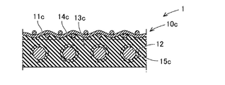
- Electrostatic sheet 10c of the fifth example The configuration of the electrostatic sheet 10c of the fifth example will be described with reference to FIGS. 7 and 8.
- the electrostatic sheet 10 includes at least an electrode sheet 11c, a heater 12, an insulating layer 13c, an electrode fusion layer 14c, and a heater fusion layer 15c.
- the electrode sheet 11c has conductivity and flexibility and stretchability in the plane direction.
- the electrode sheet 11c is, for example, a conductive cloth.
- the insulating layer 13c is formed of, for example, a thermoplastic material, particularly a thermoplastic elastomer.
- the electrode fusing layer 14c may be configured as a part of the insulating layer 13c or may be joined to the insulating layer 13c as a separate member.
- the heater fusion layer 15c is made of a fusion material.
- the heater fusing layer 15c joins the heater 12 and the insulating layer 13c by fusing (heat fusing) the heater fusing layer 15c itself.
- the heater 12 is joined by the heater fusion layer 15c while being embedded in the insulating layer 13c.
- the heater fusion bonding layer 15c may be configured as a part of the insulating layer 13c or may be joined to the insulating layer 13c as a separate member.
- the heater fusion bonding layer 15c is formed of a thermoplastic material that is a fusion bonding material, and is configured as a part of the insulating layer 13c.
- the heater fusing layer 15c as a part of the insulating layer 13c joins the heater 12 and the insulating layer 13c by fusing themselves.
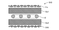
- a method of manufacturing the electrostatic sheet 10c will be described with reference to FIG.
- the material of the insulating layer 13c is assumed to be formed of a thermoplastic material.
- a laminated body is prepared in which the electrode sheet 11c, the first material 13c1 of the insulating layer 13c, the heater 12, and the second material 13c2 of the insulating layer 13c are laminated in this order (preparation step). Then, the laminated body is heated and pressed (heating and pressing step). Then, the first material 13c1 of the insulating layer 13c softens and functions as a fusion material, and is bonded to the electrode sheet 11c. The portion fused to the electrode sheet 11c becomes the electrode fusion layer 14c.
- first material 13c1 and the second material 13c2 of the insulating layer 13c are softened to function as a fusion material and are bonded to the heater 12.
- the portion fused to the heater 12 becomes the heater fusion layer 15c.
- the first material 13c1 and the second material 13c2 of the insulating layer 13c are integrated to form the insulating layer 13c.
- the heater 12 is embedded in the insulating layer 13c. In this way, the electrostatic sheet 10c of the transducer 1 is manufactured.
- the insulating layer 13c is formed of a thermoplastic material, and the electrode fusing layer 14c and the heater fusing layer 15c are formed as a part of the insulating layer 13c. Therefore, dedicated members are not required for the electrode fusion layer 14c and the heater fusion layer 15c. As a result, it is possible to further reduce the cost.
- the electrode fusing layer 14c and the heater fusing layer 15c are arranged as separate members from the insulating layer 13c, the electrode sheet 11c, the material of the electrode fusing layer 14c, the insulating layer 13c, the heater fusing layer A laminated body in which the material of 15c and the heater 12 are laminated in this order is prepared (preparation step). Then, the laminated body is heated and pressed (heating and pressing step). Then, the material of the electrode fusion layer 14c softens and functions as a fusion material to bond the electrode sheet 11c and the insulating layer 13c. Further, the material of the heater fusion bonding layer 15c softens and functions as a fusion bonding material to bond the heater 12 and the insulating layer 13c.
- Example of transducer 1 A plurality of examples will be given to describe the transducer 1 having the basic configuration of the transducer 1 described above and including other elements.
- the electrostatic sheet 10 of the transducer 1 is configured to have a pair of electrode sheets.
- the configuration of the transducer 100 of the first example will be described with reference to FIG.
- the transducer 100 includes an electrostatic sheet 110 having a heater function.
- the electrostatic sheet 110 is flexible as a whole.
- the electrostatic sheet 110 has a configuration using the electrostatic sheet 10a or 10b of any one of the first to fourth examples.
- the same components as those of the electrostatic sheets 10a and 10b are designated by the same reference numerals and detailed description thereof will be omitted.
- the electrostatic sheet 110 includes at least the first electrode sheet 116, the second electrode sheet 11a, the heater 12, the interelectrode insulating layer 117, the back surface side insulating layers 13a and 13b, and the back surface side fusion bonding layers 14a and 14b.
- the first electrode sheet 116 has the same configuration as the electrode sheet 11a in the electrostatic sheet 10a, 10b of any one of the first to fourth examples.
- the first electrode sheet 116 is arranged on the surface layer side.
- the second electrode sheet 11a corresponds to a portion functioning as the electrode sheet 11a in any one of the electrostatic sheets 10a and 10b of the first to fourth examples.
- the second electrode sheet 11a is arranged to face the back surface of the first electrode sheet 116.
- the heater 12 corresponds to a portion functioning as the heater 12 in any one of the electrostatic sheets 10a and 10b of the first to fourth examples.
- the heater 12 is arranged to face the back surface of the second electrode sheet 11a.
- the inter-electrode insulating layer 117 is formed in a sheet shape and is sandwiched between the first electrode sheet 116 and the second electrode sheet 11a.
- the interelectrode insulating layer 117 is made of an elastically deformable material.
- the inter-electrode insulating layer 117 is formed of, for example, a thermoplastic material, particularly a thermoplastic elastomer. Further, the inter-electrode insulating layer 117 may be made of a non-thermoplastic elastomer foam material, a non-woven fabric or the like.
- the interelectrode insulating layer 117 functions as a dielectric layer in the electrostatic sheet.
- the back side insulating layers 13a and 13b are formed in a sheet shape and are sandwiched between the second electrode sheet 11a and the heater 12.
- the back surface side insulating layers 13a and 13b correspond to the portions functioning as the insulating layers 13a and 13b in the electrostatic sheets 10a and 10b of any one of the first to fourth examples.
- the back surface side insulating layers 13a and 13b are formed of the same material as the interelectrode insulating layer 117. Since both are made of the same material, the cost can be reduced.
- the back side fusion layers 14a and 14b are formed of a fusion material.
- the back side fusion layers 14a and 14b join the second electrode sheet 11a and the back side insulation layers 13a and 13b, and function as the electrode fusion layers 14a and 14b in the electrostatic sheets 10a and 10b of the first example. Corresponding to.
- the first electrode sheet 116, the inter-electrode insulating layer 117, and the second electrode sheet 11a are integrally formed in a pre-laminated state (preparation step). Further, the heater 12 and the back surface side insulating layers 13a and 13b are integrally formed in advance (preparation step). And the laminated body which laminated
- the second electrode sheet 11a is softened and fused to the uneven surfaces of the back surface side insulating layers 13a and 13b. That is, a part of the second electrode sheet 11a forms the back surface side fusion bonding layers 14a and 14b. In this way, the electrostatic sheet 110 of the transducer 100 of the first example is manufactured.
- the first electrode sheet 116, the second electrode sheet 11a, and the inter-electrode insulating layer 117 are located on the front side of the heater 12. That is, the heater 12 is not located between the first electrode sheet 116 and the second electrode sheet 11a and on the surface side of the first electrode sheet 116. As a result, it is possible to suppress the influence of the heater 12 on the detection performance or the driving performance, so that the high detection performance or the driving performance can be exhibited.
- the interelectrode insulating layer 117 can sufficiently function as a heater by using a material having good thermal conductivity.
- the back surface side insulating layers 13a and 13b that are in direct contact with the heater 12 are formed of a material having good thermal conductivity, sufficient heat is diffused before the heat becomes sufficiently high, so that sufficient heat is generated on the surface layer. Hard to be transmitted to. Therefore, by forming the back side insulating layers 13a and 13b with a material having a poor thermal conductivity to some extent, heat can be effectively transferred to the surface layer.
- the back surface side insulating layers 13a and 13b are made of a foam material, a non-woven fabric, a woven fabric or the like having pores formed therein, heat can be more effectively transferred to the surface layer.
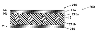
- the configuration of the transducer 200 of the second example will be described with reference to FIG.
- the transducer 200 includes an electrostatic sheet 210 having a heater function.
- the electrostatic sheet 110 is flexible as a whole.
- the electrostatic sheet 210 has a configuration using any one of the electrostatic sheets 10a and 10b of the first to fourth examples. In this example, the same components as those of the electrostatic sheets 10a and 10b are designated by the same reference numerals and detailed description thereof will be omitted.
- the electrostatic sheet 210 includes at least a first electrode sheet 11a, a heater 12, a second electrode sheet 216, a first insulating layer 213a (13a, 13b), a second insulating layer 213b (13a, 13b), and a first electrode fusion bonding.
- the layers 14a and 14b and the second electrode fusion layer 217 are provided.
- the first electrode sheet 11a has the same structure as the electrode sheet 11a in the electrostatic sheet 10a, 10b of any one of the first to fourth examples.
- the first electrode sheet 11a is arranged on the surface layer side.
- the heater 12 is arranged to face the back surface of the first electrode sheet 11a.
- the second electrode sheet 216 has the same structure as the first electrode sheet 11a.
- the second electrode sheet 216 is arranged to face the back surface side of the heater 12. That is, the heater 12 is interposed between the first electrode sheet 11a and the second electrode sheet 216.
- the first insulating layer 213a is formed in a sheet shape and is sandwiched between the first electrode sheet 11a and the heater 12.
- the first insulating layer 213a functions as a part of the insulating layers 13a and 13b in the electrostatic sheets 10a and 10b of any one of the first to fourth examples.
- the second insulating layer 213b is formed in a sheet shape and is sandwiched between the heater 12 and the second electrode sheet 216.
- the second insulating layer 213b functions as another part of the insulating layers 13a and 13b in the electrostatic sheets 10a and 10b of the first to fourth examples. That is, the first insulating layer 213a and the second insulating layer 213b are made of the same material.
- the first electrode fusion layers 14a and 14b are made of a fusion material.
- the first electrode fusing layers 14a and 14b join the first electrode sheet 11a and the first insulating layer 213a.
- the first electrode fusing layers 14a and 14b function as the electrode fusing layers 14a and 14b in any one of the electrostatic sheets 10a and 10b of the first to fourth examples.
- the second electrode fusion layer 217 is made of a fusion material.
- the second electrode fusing layer 217 joins the second electrode sheet 216 and the second insulating layer 213b.
- the second electrode fusing layer 217 has the same configuration as the first electrode fusing layers 14a and 14b.
- a method of manufacturing the second example transducer 200 will be described.
- the first insulating layer 213a, the heater 12, and the second insulating layer 213b are integrally formed in advance.
- a laminated body in which the first electrode sheet 11a, the integrally molded product, and the second electrode sheet 216 are laminated in this order is prepared (preparation step).
- the first electrode sheet 11a is softened and fused to the uneven surface of the first insulating layer 213a. That is, a part of the first electrode sheet 11a forms the first electrode fusing layers 14a and 14b.
- the second electrode sheet 216 is softened and fused to the uneven surface of the second insulating layer 213b. That is, a part of the second electrode sheet 216 forms the second electrode fusing layer 217. In this way, the electrostatic sheet 210 of the transducer 200 of the second example is manufactured.
- the heater 12 is sandwiched between the first electrode sheet 11a and the second electrode sheet 216. Therefore, the thickness of the electrostatic sheet 210 can be reduced. Therefore, a small electrostatic sheet 210 can be manufactured.
- the configuration of the transducer 300 of the third example will be described with reference to FIG.
- the transducer 300 includes an electrostatic sheet 310 having a heater function.
- the electrostatic sheet 310 is flexible as a whole.
- the electrostatic sheet 310 has a configuration using one of the electrostatic sheets 10a and 10b of the first to fourth examples.
- the same components as those of the electrostatic sheets 10a and 10b are designated by the same reference numerals, and detailed description thereof will be omitted.
- the electrostatic sheet 310 includes at least the heater 12, the first electrode sheet 11a, the second electrode sheet 316, the surface side insulating layers 13a and 13b, the inter-electrode insulating layer 317, and the surface side fusion layers 14a and 14b.
- the first electrode sheet 11a has the same configuration as the electrode sheet 11a in the electrostatic sheets 10a and 10b of any one of the first to fourth examples.
- the first electrode sheet 116 is arranged on the surface layer side.
- the heater 12 is arranged on the surface side.
- the heater 12 corresponds to a portion functioning as the heater 12 in any one of the electrostatic sheets 10a and 10b of the first to fourth examples.
- the first electrode sheet 11a is arranged to face the back surface of the heater 12.
- the 1st electrode sheet 11a respond
- the second electrode sheet 316 is arranged to face the back surface of the first electrode sheet 11a.
- the second electrode sheet 316 has the same configuration as the first electrode sheet 11a.
- the front-side insulating layers 13a and 13b are formed in a sheet shape and sandwiched between the heater 12 and the first electrode sheet 11a.
- the front surface side insulating layers 13a and 13b correspond to the portions functioning as the insulating layers 13a and 13b in the electrostatic sheets 10a and 10b of any one of the first to fourth examples.
- the interelectrode insulating layer 317 is formed in a sheet shape, and is sandwiched between the first electrode sheet 11a and the second electrode sheet 316.
- the inter-electrode insulating layer 317 is made of an elastically deformable material.
- the inter-electrode insulating layer 317 is formed of, for example, a thermoplastic material, particularly a thermoplastic elastomer. Further, the inter-electrode insulating layer 317 may be made of a non-thermoplastic elastomer foam material, a non-woven fabric, or the like.
- the interelectrode insulating layer 317 functions as a dielectric layer in the electrostatic sheet.
- the surface-side insulating layers 13a and 13b and the inter-electrode insulating layer 317 are made of different materials.
- the surface side insulating layers 13a and 13b are formed of a material having a higher thermal conductivity than the interelectrode insulating layer 317.
- the interelectrode insulating layer 317 does not need to be a material having high thermal conductivity. By forming the interelectrode insulating layer 317 from a material that effectively exhibits a dielectric, the detection performance or drive performance of the electrostatic sheet 310 can be improved.
- the first electrode sheet 11a, the inter-electrode insulating layer 317, and the second electrode sheet 316 are integrally formed in a previously laminated state (preparation step). Further, the heater 12 and the front surface side insulating layers 13a and 13b are integrally formed in advance (preparation step). And the laminated body which laminated
- the first electrode sheet 11a is softened and fused to the uneven surfaces of the surface-side insulating layers 13a and 13b. That is, a part of the first electrode sheet 11a forms the surface-side fusion bonding layers 14a and 14b. In this way, the electrostatic sheet 310 of the transducer 300 of the third example is manufactured.
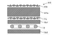
- the transducer 400 includes a base material 430 and an electrostatic sheet 410 attached to the attachment surface of the base material 430.
- the electrostatic sheet 410 has a heater function.
- the electrostatic sheet 410 is flexible as a whole.
- the electrostatic sheet 410 has a configuration using the electrostatic sheet 10c of the fifth example.
- parts having the same configurations as those of the electrostatic sheet 10c of the fifth example are designated by the same reference numerals, and detailed description thereof will be omitted.
- the electrostatic sheet 410 includes at least the first electrode sheet 416, the second electrode sheet 11c, the heater 12, the inter-electrode insulating layer 417, the back side insulating layer 13c, the inter-electrode first fusion layer 418, and the inter-electrode second fusion layer.
- a layer 419, a backside fusion layer 14c, and a heater fusion layer 15c are provided.
- the electrostatic sheet 410 further includes a surface protective layer 420, a protective fusion bonding layer 421, and a base material fusion bonding layer 422.
- the electrostatic sheet 410 may be configured without the surface protective layer 420, the protective fusion bonding layer 421, and the base material fusion bonding layer 422.
- the first electrode sheet 416 has the same configuration as the electrode sheet 11c in the electrostatic sheet 10c of the fifth example.
- the first electrode sheet 416 is arranged on the surface layer side.
- the second electrode sheet 11c corresponds to a portion that functions as the electrode sheet 11c in the electrostatic sheet 10c of the fifth example.
- the second electrode sheet 11c is arranged to face the back surface of the first electrode sheet 416.
- the heater 12 corresponds to a portion that functions as the heater 12 in the electrostatic sheet 10c of the fifth example.
- the heater 12 is arranged to face the back surface of the second electrode sheet 11c.
- the inter-electrode insulating layer 417 is formed in a sheet shape and is sandwiched between the first electrode sheet 416 and the second electrode sheet 11c.
- the interelectrode insulating layer 417 is made of an elastically deformable material.
- the inter-electrode insulating layer 417 is formed of, for example, a thermoplastic material, particularly a thermoplastic elastomer. Further, the inter-electrode insulating layer 417 can also be made of a non-thermoplastic elastomer foam material, non-woven fabric, or the like.
- the interelectrode insulating layer 417 functions as a dielectric layer in the electrostatic sheet.
- the back side insulating layer 13c is formed in a sheet shape and is sandwiched between the second electrode sheet 11c and the heater 12.
- the back surface side insulating layer 13c corresponds to a portion functioning as the insulating layer 13c in the electrostatic sheet 10c of the fifth example.
- the back surface side insulating layer 13c is formed of the same material as the interelectrode insulating layer 417. Since both are made of the same material, the cost can be reduced.
- the first inter-electrode fusion layer 418 is made of a fusion material. That is, the inter-electrode first fusion-bonding layer 418 exerts a bonding force by being subjected to heat treatment. For example, the inter-electrode first fusion bonding layer 418 exerts a bonding force by being heated and pressed.
- the inter-electrode first fusion bonding layer 418 joins the first electrode sheet 416 and the inter-electrode insulating layer 417.
- the first inter-electrode fusion layer 418 may be configured as a part of the inter-electrode insulating layer 417, or may be joined to the inter-electrode insulating layer 417 as a separate member.
- the inter-electrode first fusion-bonding layer 418 is formed of a thermoplastic material that is a fusion-bonding material, and is configured as a part of the inter-electrode insulating layer 417.
- the inter-electrode first fusion-bonding layer 418 as a part of the inter-electrode insulation layer 417 joins the first electrode sheet 416 and the inter-electrode insulation layer 417 by fusion (thermal fusion).
- the second inter-electrode fusion layer 419 is made of a fusion material.
- the inter-electrode second fusing layer 419 is similar to the inter-electrode first fusing layer 418.
- the inter-electrode second fusion bonding layer 419 joins the inter-electrode insulating layer 417 and the second electrode sheet 11c.
- the inter-electrode second fusion bonding layer 419 may be configured as a part of the inter-electrode insulating layer 417 or may be joined to the inter-electrode insulating layer 417 as a separate member.
- the inter-electrode second fusion-bonding layer 419 is formed of a thermoplastic material that is a fusion-bonding material, and is configured as a part of the inter-electrode insulating layer 417.
- the inter-electrode second fusion bonding layer 419 as a part of the inter-electrode insulation layer 417 joins the inter-electrode insulation layer 417 and the second electrode sheet 11c by fusion (thermal fusion).
- the backside fusion layer 14c is formed of a fusion material.
- the back surface side fusion layer 14c corresponds to a portion which joins the second electrode sheet 11c and the back surface side insulation layer 13c and functions as the electrode fusion layer 14c in the electrostatic sheet 10c of the fifth example.
- the heater fusion layer 15c is made of a fusion material.
- the heater fusion bonding layer 15c joins the back surface side insulating layer 13c and the heater 12 and corresponds to a portion functioning as the heater fusion bonding layer 15c in the electrostatic sheet 10c of the fifth example.
- the heater 12 is bonded by the heater fusion bonding layer 15c on the back surface side of the second electrode sheet 11c while being embedded in the back surface side insulating layer 13c.
- the surface protection layer 420 is formed in a sheet shape and covers the surface side of the first electrode sheet 416.
- the surface protection layer 420 may be formed of a thermoplastic material, particularly a thermoplastic elastomer.
- the surface protection layer 420 may be formed of a part of the material of the inter-electrode insulating layer 417, or may be formed as a separate member from the inter-electrode insulating layer 417.
- a resin insulating sheet having an adhesive layer or an adhesive layer may be used instead of the thermoplastic material.
- the protective fusion bonding layer 421 is made of a fusion bonding material.
- the protective fusion bonding layer 421 joins the first electrode sheet 416 and the surface protective layer 420 together.
- the protective fusion bonding layer 421 may be configured as a part of the surface protective layer 420, or may be joined to the surface protective layer 420 as a separate member. Further, the protective fusion bonding layer 421 may be formed of a part of the material of the interelectrode insulating layer 417. However, when the surface protective layer 420 is an insulating sheet, the protective fusion bonding layer 421 becomes unnecessary.
- the base material fusion layer 422 is made of a fusion material, and joins the back surface side insulating layer 13c and the mounting surface of the base material 430.
- the base material fusion bonding layer 422 may be configured as a part of the back surface side insulating layer 13c, or may be joined to the back surface side insulating layer 13c as a separate member.
- the first electrode sheet 416, the material 417a of the inter-electrode insulating layer 417, the second electrode sheet 11c, the first material 13c1 of the back side insulating layer 13c, the heater 12, and the second material 13c2 of the back side insulating layer 13c were laminated in this order.
- a laminated body is prepared (preparation process). Then, the laminated body is heated and pressed (heating and pressing step).
- the material 417a of the interelectrode insulating layer 417 softens and functions as a fusion material, and is bonded to the first electrode sheet 416.
- the portion fused to the first electrode sheet 416 becomes the inter-electrode first fusion layer 418.
- the material 417a of the inter-electrode insulating layer 417 passes through the through hole of the first electrode sheet 416 and moves to the surface layer side of the first electrode sheet 416.
- the surface protection layer 420 is formed of the material 417a of the interelectrode insulating layer 417.
- the portion fused to the surface protective layer 420 and the first electrode sheet 416 becomes the protective fused layer 421.
- the material 417a of the interelectrode insulating layer 417 softens and functions as a fusion material, and is bonded to the second electrode sheet 11c.
- the portion fused to the second electrode sheet 11c becomes the inter-electrode second fused layer 419.
- the material 417a of the inter-electrode insulating layer 417 passes through the through hole of the second electrode sheet 11c and moves to the back surface side of the second electrode sheet 11c. Then, the material 417a that has moved to the back surface side of the second electrode sheet 11c is joined to the first material 13c1 of the back surface side insulating layer 13c.
- the first material 13c1 of the back surface side insulating layer 13c softens and functions as a fusion material, and is bonded to the back surface side of the second electrode sheet 11c. That is, a part of the material 417a of the interelectrode insulating layer 417 and a part of the first material 13c1 of the back surface side insulating layer 13c become the back surface side fusion layer 14c.
- the first material 13c1 and the second material 13c2 of the back surface side insulating layer 13c are softened to function as a fusion material and are bonded to the heater 12.
- the portion fused to the heater 12 becomes the heater fusion layer 15c.
- the back surface side insulating layer 13c is formed by integrating the first material 13c1 and the second material 13c2 of the back surface side insulating layer 13c.
- the heater 12 is in a state of being embedded in the back side insulating layer 13c. In this way, the electrostatic sheet 410 of the transducer 400 is manufactured.
- the base material fusion layer 422 can be formed by heating the back surface side insulating layer 13c and applying pressure to the base material 430. In this way, the transducer 400 is manufactured.
- the surface protection layer 420 is formed of the material 417a of the inter-electrode insulating layer 417, but an insulating sheet made of resin different from the material 417a of the inter-electrode insulating layer 417 is used. You can also
- a first laminated body in which the first electrode sheet 416, the material 417a of the interelectrode insulating layer 417, and the second electrode sheet 11c are laminated in this order is prepared (first laminated body preparing step), and the first laminated body is heated and heated. By pressing, the first molded body is molded (first molded body molding step). Then, a second laminated body is prepared by laminating the first material 13c1 of the back side insulating layer 13c, the heater 12, and the second material 13c2 of the back side insulating layer 13c in this order (second laminated body preparing step). The second molded body is molded by heating and pressing the laminated body (second molded body molding step).
- final laminate preparation step the final laminate in which the first compact and the second compact are laminated is prepared (final laminate preparation step), and the final laminate is heated and pressed to manufacture the electrostatic sheet 410 ( Final heat and pressure step).
- the first electrode sheet 416, the second electrode sheet 11c, and the inter-electrode insulating layer 417 are located on the surface side of the heater 12. That is, the heater 12 is not located between the first electrode sheet 416 and the second electrode sheet 11c and on the front surface side of the first electrode sheet 416. As a result, it is possible to suppress the influence of the heater 12 on the detection performance or the driving performance, so that the high detection performance or the driving performance can be exhibited.
- the inter-electrode insulating layer 417 and the back surface insulating layer 13c are made of a material having good thermal conductivity, so that the heater 12 sufficiently functions as a heater. can do.
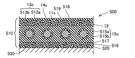
- the transducer 500 includes a base material 530 and an electrostatic sheet 510 attached to an attachment surface of the base material 530.
- the electrostatic sheet 510 has a heater function.
- the electrostatic sheet 510 is flexible as a whole.
- the electrostatic sheet 510 has a configuration using the electrostatic sheet 10c of the fifth example. Therefore, in this example, parts having the same configurations as those of the electrostatic sheet 10c of the fifth example are designated by the same reference numerals, and detailed description thereof will be omitted.
- the electrostatic sheet 510 includes at least the first electrode sheet 11c, the heater 12, the second electrode sheet 516, the first insulating layer 513a, the second insulating layer 513b, the first electrode fusion layer 14c, and the first heater fusion layer 515a.
- the electrostatic sheet 510 further includes a surface protective layer 518, a protective fusion bonding layer 519, and a base material fusion bonding layer 520.
- the electrostatic sheet 510 may be configured without the surface protective layer 518, the protective fusion bonding layer 519, and the base material fusion bonding layer 520.
- the first electrode sheet 11c is arranged on the surface side.
- the first electrode sheet 11c corresponds to a portion that functions as the electrode sheet 11c in the electrostatic sheet 10c of the fifth example.
- the heater 12 is arranged to face the back surface of the first electrode sheet 11c.
- the heater 12 corresponds to a portion that functions as the heater 12 in the electrostatic sheet 10c of the fifth example.
- the second electrode sheet 516 has the same structure as the first electrode sheet 11c.
- the second electrode sheet 516 is arranged to face the back surface side of the heater 12. That is, the heater 12 is interposed between the first electrode sheet 11c and the second electrode sheet 516.
- the first insulating layer 513a is formed in a sheet shape and is sandwiched between the first electrode sheet 11c and the heater 12.
- the first insulating layer 513a functions as a part of the insulating layer 13c in the electrostatic sheet 10c of the fifth example.
- the second insulating layer 513b is formed in a sheet shape and is sandwiched between the heater 12 and the second electrode sheet 516.
- the second insulating layer 513b functions as another part of the insulating layer 13c in the electrostatic sheet 10c of the fifth example. That is, the first insulating layer 513a and the second insulating layer 513b are formed of the same material.
- the first electrode fusion layer 14c is formed of a fusion material.
- the first electrode fusing layer 14c joins the first electrode sheet 11c and the first insulating layer 513a.
- the first electrode fusing layer 14c may be configured as a part of the first insulating layer 513a or may be joined to the first insulating layer 513a as a separate member.
- the first heater fusion layer 515a is made of a fusion material.
- the first heater fusion bonding layer 515a bonds the first insulating layer 513a and the heater 12. That is, the first heater fusion bonding layer 515a is a portion that is fused to the front surface side of the heater 12.
- the first heater fusion bonding layer 515a may be configured as a part of the first insulating layer 513a, or may be joined to the first insulating layer 513a as a separate member.
- the second heater fusion layer 515b is made of a fusion material.
- the second heater fusion bonding layer 515b joins the heater 12 and the second insulating layer 513b. That is, the second heater fusion bonding layer 515b is a portion that is fused to the back surface side of the heater 12.
- the second heater fusion bonding layer 515b may be configured as a part of the second insulating layer 513b, or may be joined to the second insulating layer 513b as a separate member.
- the first heater fusing layer 515a and the second heater fusing layer 515b function as the heater fusing layer 15c in the electrostatic sheet 10c of the fifth example.
- the heater 12 is embedded in the first insulating layer 513a and the second insulating layer 513b between the first electrode sheet 11c and the second electrode sheet 516, and is embedded in the first heater fusion layer 515a and the second heater layer 515a. They are joined by a heater fusion layer 515b.
- the second electrode fusion layer 517 is made of a fusion material.
- the second electrode fusing layer 517 joins the second insulating layer 513b and the second electrode sheet 516 together.
- the second electrode fusing layer 517 may be configured as a part of the second insulating layer 513b, or may be joined to the second insulating layer 513b as a separate member.
- the surface protective layer 518 is formed in a sheet shape and covers the surface side of the first electrode sheet 11c.
- the surface protective layer 518 may be formed of a thermoplastic material, particularly a thermoplastic elastomer.
- the surface protection layer 518 may be formed of a part of the material of the first insulating layer 513a, or may be formed as a separate member from the first insulating layer 513a. Further, as the surface protective layer 518, a resin insulating sheet having an adhesive layer or an adhesive layer may be applied instead of the thermoplastic material.
- the protective fusing layer 519 is configured similarly to the protective fusing layer 421 in the transducer 400 of the fourth example.
- the base material fusion bonding layer 520 is formed of a fusion bonding material, and joins the second insulating layer 513b and the mounting surface of the base material 530.
- the base material fusion bonding layer 520 may be configured as a part of the second insulating layer 513b or may be joined to the second insulating layer 513b as a separate member.
- the material 13c1 of the first insulating layer 513a softens and functions as a fusion material, and is bonded to the first electrode sheet 11c.
- the portion fused to the first electrode sheet 11c becomes the first electrode fusion layer 14c.
- the material 13c1 of the first insulating layer 513a passes through the through holes of the first electrode sheet 11c to form the surface protective layer 518 and the protective fusion bonding layer 519. This point is the same as the surface protective layer 420 and the protective fusion bonding layer 421 in the transducer 400 of the fourth example.
- the material 13c1 of the first insulating layer 513a and the material 13c2 of the second insulating layer 513b are softened to function as a fusion material and are bonded to the heater 12.
- the portions fused to the heater 12 become the first heater fusion layer 515a and the second heater fusion layer 515b.
- the material 13c1 of the first insulating layer 513a and the material 13c2 of the second insulating layer 513b are integrated to form the insulating layer 13c.
- the heater 12 is embedded in the insulating layer 13c.
- the material 13c2 of the second insulating layer 513b softens and functions as a fusion material, and is bonded to the second electrode sheet 516.
- the portion fused to the second electrode sheet 516 becomes the second electrode fusion layer 517.
- the material 13c2 of the second insulating layer 513b passes through the through holes of the second electrode sheet 516 and moves to the back surface side of the second electrode sheet 516.
- the material 13c2 that has moved to the back surface side of the second electrode sheet 516 is joined to the back surface side of the second electrode sheet 516. That is, the material 13c2 of the second insulating layer 513b becomes the base material fusion bonding layer 520. In this way, the electrostatic sheet 510 of the transducer 500 is manufactured.
- the base material fusion layer 520 heats the base material fusion layer 520 and pressurizes it against the base material 530 when the electrostatic sheet 510 is attached to the base material 530. 520 is fused to substrate 530. In this way, the transducer 500 is manufactured.
- first laminated body preparing step By preparing a first laminated body in which the first insulating layer 513a, the heater 12, and the second insulating layer 513b are laminated in this order (first laminated body preparing step), and heating and pressurizing the first laminated body, The first molded body is molded (first molded body molding step).
- stacked the 1st electrode sheet 11c, the said 1st molded object, and the 2nd electrode sheet 516 in order was prepared (2nd laminated body preparation process), and the said 2nd laminated body was heated and added.
- the electrostatic sheet 510 of the transducer 500 is manufactured (heating and pressing step).
- the heater 12 is sandwiched between the first electrode sheet 11c and the second electrode sheet 516. Therefore, the thickness of the electrostatic sheet 510 can be reduced. Therefore, a small electrostatic sheet 510 can be manufactured.
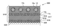
- the transducer 600 includes a base material 630 and an electrostatic sheet 610 attached to an attachment surface of the base material 630.
- the heater 12 is arranged on the back surface side of the second electrode sheet 11c, whereas in the electrostatic sheet 610 of the present example, the heater 12 is arranged on the first electrode sheet 11c. They are different in that they are arranged on the surface side of.
- the electrostatic sheet 610 of this example has a heater function and is flexible as a whole. Further, the electrostatic sheet 610 has a configuration using the electrostatic sheet 10c of the fifth example. In this example, parts having the same configurations as those of the electrostatic sheet 10c of the fifth example are designated by the same reference numerals, and detailed description thereof will be omitted.
- the electrostatic sheet 610 includes at least the heater 12, the first electrode sheet 11c, the second electrode sheet 616, the surface-side insulating layer 13c, the inter-electrode insulating layer 617, the heater fusion layer 15c, the surface-side fusion layer 14c, and the inter-electrode space.
- the first fusion bonding layer 618 and the inter-electrode second fusion bonding layer 619 are provided.
- the electrostatic sheet 610 further includes a base material fusion bonding layer 620.
- the heater 12 is arranged on the surface side.
- the heater 12 corresponds to a portion that functions as the heater 12 in the electrostatic sheet 10c of the fifth example.
- the first electrode sheet 11c is arranged to face the back surface of the heater 12.
- the first electrode sheet 11c corresponds to a portion that functions as the electrode sheet 11c in the electrostatic sheet 10c of the fifth example.
- the second electrode sheet 616 is arranged to face the back surface of the first electrode sheet 11c.
- the second electrode sheet 616 has the same configuration as the first electrode sheet 11c.
- the front-side insulating layer 13c is formed in a sheet shape and is sandwiched between the heater 12 and the first electrode sheet 11c.
- the front surface side insulating layer 13c corresponds to a portion functioning as the insulating layer 13c in the electrostatic sheet 10c of the fifth example.
- the inter-electrode insulating layer 617 is formed in a sheet shape and is sandwiched between the first electrode sheet 11c and the second electrode sheet 616.
- the inter-electrode insulating layer 617 is made of an elastically deformable material.
- the inter-electrode insulating layer 617 is formed of, for example, a thermoplastic material, particularly a thermoplastic elastomer.
- the inter-electrode insulating layer 617 may be formed of a non-thermoplastic elastomer foam material, a non-woven fabric, or the like.
- the interelectrode insulating layer 617 functions as a dielectric layer in the electrostatic sheet.
- the surface-side insulating layer 13c and the inter-electrode insulating layer 617 are made of different materials.
- the surface-side insulating layer 13c is made of a material having a higher thermal conductivity than the interelectrode insulating layer 617.
- the interelectrode insulating layer 617 does not need to be a material having high thermal conductivity. By forming the interelectrode insulating layer 617 from a material that effectively exhibits a dielectric, the detection performance or drive performance of the electrostatic sheet 610 can be improved.
- the heater fusing layer 15c is made of a fusing material, and joins the heater 12 and the front side insulating layer 13c.
- the heater fusing layer 15c corresponds to a portion that functions as the heater fusing layer 15c in the electrostatic sheet 10c of the fifth example.
- the heater 12 is joined to the first electrode sheet 11c by the heater fusion layer 15c while being embedded in the front-side insulating layer 13c on the front side.
- the front-side fusion layer 14c is formed of a fusion material, and joins the front-side insulating layer 13c and the first electrode sheet 11c.
- the front-side fusion-bonding layer 14c corresponds to a portion functioning as the electrode fusion-bonding layer 14c in the electrostatic sheet 10c of the fifth example.
- the first inter-electrode fusion layer 618 is made of a fusion material and joins the first electrode sheet 11c and the inter-electrode insulating layer 617.
- the inter-electrode first fusion-bonding layer 618 may be configured as a part of the inter-electrode insulating layer 617, or may be joined to the inter-electrode insulating layer 617 as a separate member.
- the inter-electrode first fusion-bonding layer 618 corresponds to the inter-electrode first fusion-bonding layer 418 in the transducer 400 of the fourth example.
- the inter-electrode second fusion-bonding layer 619 is made of a fusion-bonding material, and joins the inter-electrode insulating layer 617 and the second electrode sheet 616.
- the inter-electrode second fusion bonding layer 619 may be configured as a part of the inter-electrode insulating layer 617, or may be joined to the inter-electrode insulating layer 617 as a separate member.
- the inter-electrode second fusing layer 619 corresponds to the inter-electrode second fusing layer 419 in the transducer 400 of the fourth example.
- the base material fusion layer 620 is made of a fusion material, and joins the interelectrode insulating layer 617 and the mounting surface of the base material 630.
- the base material fusion bonding layer 620 may be configured as a part of the interelectrode insulating layer 617, or may be joined to the interelectrode insulating layer 617 as a separate member.
- the first material 13c1 of the front-side insulating layer 13c, the heater 12, the second material 13c2 of the front-side insulating layer 13c, the first electrode sheet 11c, the material 617a of the inter-electrode insulating layer 617, and the second electrode sheet 616 were laminated in this order.
- a laminated body is prepared (preparation process). Then, the laminated body is heated and pressed (heating and pressing step).
- the first material 13c1 and the second material 13c2 of the surface-side insulating layer 13c are softened to function as a fusion material and are bonded to the heater 12.
- the portion fused to the heater 12 becomes the heater fusion layer 15c.
- the first material 13c1 and the second material 13c2 of the front surface side insulating layer 13c are integrated to form the front surface side insulating layer 13c.
- the heater 12 is in a state of being embedded in the front insulating layer 13c.
- the material 617a of the inter-electrode insulating layer 617 softens and functions as a fusion material, and is bonded to the first electrode sheet 11c.
- the portion fused to the first electrode sheet 11c becomes the inter-electrode first fusion layer 618.
- the material 617a of the inter-electrode insulating layer 617 passes through the through hole of the first electrode sheet 11c and moves to the surface layer side of the first electrode sheet 11c. Then, the material 617a that has moved to the front surface side of the first electrode sheet 11c is joined to the second material 13c2 of the front surface side insulating layer 13c.
- the second material 13c2 of the surface-side insulating layer 13c softens and functions as a fusion material, and is bonded to the surface side of the first electrode sheet 11c. That is, a part of the material 617a of the inter-electrode insulating layer 617 and a part of the second material 13c2 of the surface-side insulating layer 13c become the surface-side fusion bonding layer 14c.
- the material 617a of the inter-electrode insulating layer 617 softens and functions as a fusion material, and is bonded to the second electrode sheet 616.
- the portion fused to the second electrode sheet 616 becomes the inter-electrode second fused layer 619.
- the material 617a of the inter-electrode insulating layer 617 passes through the through hole of the second electrode sheet 616 and moves to the back surface side of the second electrode sheet 616.
- the material 617a that has moved to the back surface side of the second electrode sheet 616 is joined to the back surface side of the second electrode sheet 616. That is, the material 617a of the inter-electrode insulating layer 617 becomes the base material fusion layer 620. In this way, the electrostatic sheet 610 of the transducer 600 is manufactured.
- the base material fusion layer 620 is heated by applying pressure to the base material 630 while heating the base material fusion layer 620. 620 is fused to the substrate 630. In this way, the transducer 600 is manufactured.
- a first laminated body in which the first electrode sheet 11c, the material 617a of the inter-electrode insulating layer 617, and the second electrode sheet 616 are laminated in this order is prepared (first laminated body preparing step), and the first laminated body is heated and heated. By pressing, the first molded body is molded (first molded body molding step).
- second laminated body preparing step a second laminated body in which the first material 13c1 of the front surface side insulating layer 13c, the heater 12, and the second material 13c2 of the front surface side insulating layer 13c are laminated in this order is prepared (second laminated body preparing step), and the second The second molded body is molded by heating and pressing the laminated body (second molded body molding step).
- the final laminated body in which the first molded body and the second molded body are laminated is prepared (final laminated body preparing step), and the final laminated body is heated and pressed to manufacture the electrostatic sheet 610 ( Final heat and pressure step).
- the heater 12 is arranged on the surface layer. Therefore, the transducer 600 can have a high heater function.
- the transducer 600 can have a high heater function.
- by using different materials for the surface-side insulating layer 13c and the inter-electrode insulating layer 617 it is possible to achieve both a high heater function and high detection performance or drive performance.
Landscapes
- Chemical & Material Sciences (AREA)
- Engineering & Computer Science (AREA)
- Ceramic Engineering (AREA)
- Surface Heating Bodies (AREA)
- Control Of Resistance Heating (AREA)
Abstract
L'invention concerne un transducteur électrostatique ayant une fonction de chauffage de telle sorte que le transducteur électrostatique peut être fabriqué sans utiliser d'adhésif volatil et un solvant organique et du temps de travail peuvent être réduits. Un transducteur électrostatique (1) comprend une feuille d'électrode (11) ; un dispositif de chauffage (12) en forme de feuille étant disposé à l'opposé de la feuille d'électrode (11) ; une couche isolante (13) en forme de feuille étant intercalée entre la feuille d'électrode (11) et le dispositif de chauffage (12) ; et une couche de fusion d'électrode (14), constituée d'un matériau de soudage, constitue une partie entre au moins l'une de la feuille d'électrode (11) et de la couche isolante (13) ou est liée à la feuille d'électrode (11) et à la couche isolante (13) en tant qu'élément séparé, et lie la feuille d'électrode (11) à la couche isolante (13) par fusion.
Priority Applications (3)
| Application Number | Priority Date | Filing Date | Title |
|---|---|---|---|
| JP2020562355A JP7364596B2 (ja) | 2018-12-24 | 2019-09-19 | 静電型トランスデューサ |
| CN201980083508.3A CN113196868B (zh) | 2018-12-24 | 2019-09-19 | 静电型换能器 |
| DE112019006387.1T DE112019006387T5 (de) | 2018-12-24 | 2019-09-19 | Elektrostatischer wandler und verfahren zu seiner herstellung |
Applications Claiming Priority (2)
| Application Number | Priority Date | Filing Date | Title |
|---|---|---|---|
| JP2018-240423 | 2018-12-24 | ||
| JP2018240423 | 2018-12-24 |
Publications (1)
| Publication Number | Publication Date |
|---|---|
| WO2020137036A1 true WO2020137036A1 (fr) | 2020-07-02 |
Family
ID=71128405
Family Applications (1)
| Application Number | Title | Priority Date | Filing Date |
|---|---|---|---|
| PCT/JP2019/036661 Ceased WO2020137036A1 (fr) | 2018-12-24 | 2019-09-19 | Transducteur électrostatique et son procédé de fabrication |
Country Status (4)
| Country | Link |
|---|---|
| JP (1) | JP7364596B2 (fr) |
| CN (1) | CN113196868B (fr) |
| DE (1) | DE112019006387T5 (fr) |
| WO (1) | WO2020137036A1 (fr) |
Cited By (2)
| Publication number | Priority date | Publication date | Assignee | Title |
|---|---|---|---|---|
| CN115698660A (zh) * | 2020-11-30 | 2023-02-03 | 住友理工株式会社 | 静电型换能器 |
| JPWO2024228311A1 (fr) * | 2023-05-01 | 2024-11-07 |
Families Citing this family (1)
| Publication number | Priority date | Publication date | Assignee | Title |
|---|---|---|---|---|
| JP7573503B2 (ja) * | 2021-09-27 | 2024-10-25 | 株式会社東海理化電機製作所 | 検出機構 |
Citations (8)
| Publication number | Priority date | Publication date | Assignee | Title |
|---|---|---|---|---|
| JPS5040252B1 (fr) * | 1970-06-13 | 1975-12-23 | ||
| JPS5212291U (fr) * | 1975-07-08 | 1977-01-28 | ||
| JP2003163070A (ja) * | 2001-11-27 | 2003-06-06 | Misawa Shokai:Kk | 発熱装置 |
| US20040178069A1 (en) * | 2003-03-14 | 2004-09-16 | Wang Da Yu | Compact ceramic sensor for fuel volatility and oxygenate concentration |
| US20120247641A1 (en) * | 2009-10-22 | 2012-10-04 | Datec Coating Corporation | Method of melt bonding high-temperature thermoplastic based heating element to a substrate |
| US20130213950A1 (en) * | 2008-12-03 | 2013-08-22 | Illinois Tool Works | Combination seat heater and occupant sensor antenna |
| JP2015046073A (ja) * | 2013-08-28 | 2015-03-12 | 住友電気工業株式会社 | タッチセンサパネル及びその製造方法 |
| JP2017010909A (ja) * | 2015-06-26 | 2017-01-12 | 株式会社クラベ | ヒータユニット及びステアリングホイール |
Family Cites Families (6)
| Publication number | Priority date | Publication date | Assignee | Title |
|---|---|---|---|---|
| JP2010519528A (ja) | 2007-02-23 | 2010-06-03 | コーニンクレッカ フィリップス エレクトロニクス エヌ ヴィ | 衣料用繊維製品内での剪断力及び圧力の測定 |
| GB2477337B (en) * | 2010-01-29 | 2011-12-07 | Gkn Aerospace Services Ltd | Electrical apparatus |
| JP2012181084A (ja) | 2011-03-01 | 2012-09-20 | Tokai Rubber Ind Ltd | 静電容量型面状センサおよびその製造方法 |
| WO2016158425A1 (fr) | 2015-03-30 | 2016-10-06 | 株式会社 イマック | Appareil de mesure de charge |
| US10067008B2 (en) | 2015-04-22 | 2018-09-04 | Vorbeck Materials Corp. | Capacitive sensor |
| US11461368B2 (en) * | 2015-06-23 | 2022-10-04 | Micro Focus Llc | Recommending analytic tasks based on similarity of datasets |
-
2019
- 2019-09-19 CN CN201980083508.3A patent/CN113196868B/zh active Active
- 2019-09-19 WO PCT/JP2019/036661 patent/WO2020137036A1/fr not_active Ceased
- 2019-09-19 JP JP2020562355A patent/JP7364596B2/ja active Active
- 2019-09-19 DE DE112019006387.1T patent/DE112019006387T5/de active Pending
Patent Citations (8)
| Publication number | Priority date | Publication date | Assignee | Title |
|---|---|---|---|---|
| JPS5040252B1 (fr) * | 1970-06-13 | 1975-12-23 | ||
| JPS5212291U (fr) * | 1975-07-08 | 1977-01-28 | ||
| JP2003163070A (ja) * | 2001-11-27 | 2003-06-06 | Misawa Shokai:Kk | 発熱装置 |
| US20040178069A1 (en) * | 2003-03-14 | 2004-09-16 | Wang Da Yu | Compact ceramic sensor for fuel volatility and oxygenate concentration |
| US20130213950A1 (en) * | 2008-12-03 | 2013-08-22 | Illinois Tool Works | Combination seat heater and occupant sensor antenna |
| US20120247641A1 (en) * | 2009-10-22 | 2012-10-04 | Datec Coating Corporation | Method of melt bonding high-temperature thermoplastic based heating element to a substrate |
| JP2015046073A (ja) * | 2013-08-28 | 2015-03-12 | 住友電気工業株式会社 | タッチセンサパネル及びその製造方法 |
| JP2017010909A (ja) * | 2015-06-26 | 2017-01-12 | 株式会社クラベ | ヒータユニット及びステアリングホイール |
Cited By (2)
| Publication number | Priority date | Publication date | Assignee | Title |
|---|---|---|---|---|
| CN115698660A (zh) * | 2020-11-30 | 2023-02-03 | 住友理工株式会社 | 静电型换能器 |
| JPWO2024228311A1 (fr) * | 2023-05-01 | 2024-11-07 |
Also Published As
| Publication number | Publication date |
|---|---|
| CN113196868A (zh) | 2021-07-30 |
| CN113196868B (zh) | 2023-09-19 |
| JP7364596B2 (ja) | 2023-10-18 |
| DE112019006387T5 (de) | 2021-10-21 |
| JPWO2020137036A1 (ja) | 2021-11-11 |
Similar Documents
| Publication | Publication Date | Title |
|---|---|---|
| CN110959295B (zh) | 换能器及其制造方法 | |
| JP7543255B2 (ja) | 静電型トランスデューサおよび静電型トランスデューサユニット | |
| CN112020635B (zh) | 静电型换能器及其制造方法 | |
| JP2008041298A (ja) | 柔軟性ptc発熱体 | |
| JP7364596B2 (ja) | 静電型トランスデューサ | |
| JP6874225B2 (ja) | 静電容量結合方式センサ | |
| JP2023093739A (ja) | トランスデューサ及びその製造方法 | |
| US12007520B2 (en) | Electrostatic transducer and electrostatic transducer unit | |
| EP4002868B1 (fr) | Transducteur électrostatique et procédé de fabrication correspondant | |
| JP2007227280A (ja) | 柔軟性ptc発熱体 | |
| JP7693572B2 (ja) | 静電型トランスデューサ | |
| KR102953264B1 (ko) | 전기매트 및 그 제조방법 | |
| JP2007227281A (ja) | 柔軟性ptc発熱体 | |
| JP7724725B2 (ja) | 静電型トランスデューサ | |
| JP2020053553A (ja) | トランスデューサ及びその製造方法 | |
| JP2013201512A (ja) | 静電型スピーカ | |
| CN116890755A (zh) | 包括碳材料制成的离散加热元件的装饰元件 | |
| JP2023056943A (ja) | 検出装置及びステアリングホイール |
Legal Events
| Date | Code | Title | Description |
|---|---|---|---|
| 121 | Ep: the epo has been informed by wipo that ep was designated in this application |
Ref document number: 19902088 Country of ref document: EP Kind code of ref document: A1 |
|
| ENP | Entry into the national phase |
Ref document number: 2020562355 Country of ref document: JP Kind code of ref document: A |
|
| 122 | Ep: pct application non-entry in european phase |
Ref document number: 19902088 Country of ref document: EP Kind code of ref document: A1 |