WO2020137324A1 - Véhicule de chantier - Google Patents
Véhicule de chantier Download PDFInfo
- Publication number
- WO2020137324A1 WO2020137324A1 PCT/JP2019/046398 JP2019046398W WO2020137324A1 WO 2020137324 A1 WO2020137324 A1 WO 2020137324A1 JP 2019046398 W JP2019046398 W JP 2019046398W WO 2020137324 A1 WO2020137324 A1 WO 2020137324A1
- Authority
- WO
- WIPO (PCT)
- Prior art keywords
- driver
- cab
- seat
- operator
- switch box
- Prior art date
- Legal status (The legal status is an assumption and is not a legal conclusion. Google has not performed a legal analysis and makes no representation as to the accuracy of the status listed.)
- Ceased
Links
Images




Classifications
-
- E—FIXED CONSTRUCTIONS
- E02—HYDRAULIC ENGINEERING; FOUNDATIONS; SOIL SHIFTING
- E02F—DREDGING; SOIL-SHIFTING
- E02F9/00—Component parts of dredgers or soil-shifting machines, not restricted to one of the kinds covered by groups E02F3/00 - E02F7/00
- E02F9/16—Cabins, platforms, or the like, for drivers
-
- E—FIXED CONSTRUCTIONS
- E02—HYDRAULIC ENGINEERING; FOUNDATIONS; SOIL SHIFTING
- E02F—DREDGING; SOIL-SHIFTING
- E02F9/00—Component parts of dredgers or soil-shifting machines, not restricted to one of the kinds covered by groups E02F3/00 - E02F7/00
- E02F9/20—Drives; Control devices
- E02F9/2004—Control mechanisms, e.g. control levers
Definitions
- the present invention relates to a work vehicle provided with a switch box equipped with various operation switches in a driver's cab.
- Patent Document 1 discloses a combine in which a work operation panel is attached to one front pillar of a pair of left and right front pillars provided in the front in a driving cabin. This work operation panel is designed so that it will be in a position overlapping the one front pillar in the projection direction from the center position of the seat surface of the driver seat to the one front pillar, and that the operation surface will face the driver seat side. It is attached to the front pillar of.
- Patent Document 1 The layout of the work operation panel in the combine described in Patent Document 1 can be applied to a work vehicle such as a wheel loader that performs cargo handling work.
- a work vehicle such as a wheel loader that performs cargo handling work.
- a work vehicle often travels on a road surface having large unevenness. Since the vehicle is likely to vibrate greatly during traveling, the position of the operator's hand is difficult to set on the operation switch to be operated due to the influence of vibration or the like. Therefore, it is difficult for the operator to operate the operation switch, and there is a possibility that the operator accidentally operates another operation switch or the like.
- an object of the present invention is to provide a work vehicle in which the operation switches can be easily operated even when the vehicle is vibrating.
- the present invention comprises a working machine attached to a frame constituting a vehicle body, and a driver's cab mounted on the frame, wherein the driver's cab is on a floor plate portion.
- a driver's seat placed on the vehicle, a pair of pillars extending in the up-down direction between the ceiling portion and the floor plate portion on the front left and right sides of the driver's seat, an operating lever for operating the working machine, and a plurality of And a switch box having an operation surface on which the operation switch of (1) is provided, and the operation lever includes one of the pair of pillars and the driver seat in the left-right direction of the driver's cab.
- the switch box is attached to the one pillar with the long side direction in the extending direction thereof, and the operation surface is a virtual line that passes through the center of the short side direction and is orthogonal.
- the lines are oriented in a direction intersecting with the backrest of the driver's seat and the center line of the driver's cab in the left-right direction, and a guide projecting outward is provided on one side of the switch box in the short side direction. It is characterized in that it is formed along the long side direction.
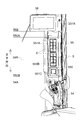
- FIG. 7 is a sectional view taken along line VII-VII in FIG. 6.
- FIG. 1 is a side view showing an external appearance of a wheel loader 1 according to an embodiment of the present invention.
- the wheel loader 1 includes a front frame 1A forming a front portion of a vehicle body, a rear frame 1B forming a rear portion of the vehicle body, a work machine 2 attached to the front frame 1A, and an operation mounted on the rear frame 1B.
- the chamber 3 is provided.
- the wheel loader 1 is an articulated work vehicle that is steered by bending the vehicle body around the center.
- the front frame 1A and the rear frame 1B are connected by a center joint 10 so as to be rotatable in the left-right direction, and the front frame 1A is bent in the left-right direction with respect to the rear frame 1B.
- the front frame 1A is provided with a pair of left and right front wheels 11A
- the rear frame 1B is provided with a pair of left and right rear wheels 11B. It should be noted that FIG. 1 shows only the left front wheel 11A and rear wheel 11B among the pair of left and right front wheels 11A and rear wheels 11B.
- the work machine 2 is attached to the front end of the lift arm 21, a lift arm 21 attached to the front frame 1A, a pair of lift arm cylinders 22 for vertically rotating the lift arm 21 with respect to the front frame 1A.
- It has a crank 25 and a plurality of pipes (not shown) for guiding pressure oil to the pair of lift arm cylinders 22 and bucket cylinders 24.
- FIG. 1 only the lift arm cylinder 22 arranged on the left side of the pair of lift arm cylinders 22 is shown by a broken line.
- the lift arm 21 rotates upward as each rod 220 of the pair of lift arm cylinders 22 extends, and rotates downward as each rod 220 contracts.
- the bucket 23 tilts (rotates upward with respect to the lift arm 21) when the rod 240 of the bucket cylinder 24 extends, and dumps (rotates downward with respect to the lift arm 21) when the rod 240 contracts. To do.
- a machine room 4 for accommodating various devices such as an engine and a hydraulic pump therein, and a counterweight 5 for maintaining a balance between the working machine 2 and the vehicle body not to tilt. And are provided.
- the cab 3 is arranged in the front part
- the counterweight 5 is arranged in the rear part
- the machine room 4 is arranged between the cab 3 and the counterweight 5.
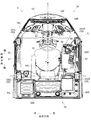
- FIG. 2 is a diagram showing the inside of the cab 3 as seen from the ceiling portion 32 side.
- FIG. 3 is a diagram when the diagonally right front side in the cab 3 is viewed along the imaginary line IL.
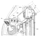
- FIG. 4 is a diagram showing the periphery of the right front pillar 331R viewed from the ceiling portion 32 side.
- FIG. 5 is an enlarged view in which the periphery of the right front pillar 331R in FIG. 3 is enlarged.
- the cab 3 includes a floor plate portion 31 mounted on the rear frame 1B, a ceiling portion 32 (see FIG. 1) that covers the floor plate portion 31 from above, and the floor plate portion 31 and the ceiling portion 32.
- a plurality of pillars 33 extending in the up-down direction between them form a frame structure in which a space for an operator to ride is formed.
- a driver's seat 51 placed on the floor plate portion 31 and a driver's seat 51 disposed in front of the driver's seat 51 are arranged in the left and right traveling directions.
- the plurality of pillars 33 are arranged on the left and right sides of the backrest 511 of the driver seat 51 and the pair of front pillars 331L and 331R arranged on the front left and right sides of the driver seat 51.
- the rear pillars 332L and 332R have a total of four pillars.
- the pair of front pillars 331L and 331R correspond to a pair of pillars that extend in the up-down direction between the ceiling portion 32 and the floor plate portion 31 in the left and right front of the driver's seat 51.
- the operator's left hand direction facing forward (front) with respect to the driver seat 51 is “left direction”, and the right hand direction is “right side”.
- Direction Further, in the following, the “horizontal direction of the vehicle body” may be simply referred to as the “horizontal direction”, and the “front-back direction of the vehicle body” may be simply referred to as the “front-back direction”.
- a front window glass 34 is provided between the pair of front pillars 331L and 331R so as to project to the working machine 2 side.
- the front window glass 34 includes a front face portion 34F located in front of the operator, a left front face portion 34L located in front of the operator's left hand, and a right front face portion 34R located in front of the operator's right hand. There is.
- the width of the front surface portion 34F in the left-right direction is smaller than the distance between the pair of front pillars 331L and 331R.
- the left front surface portion 34L faces the left front pillar 331L toward the front surface portion 34F, and the right front surface portion 34R extends from the right front pillar 331R. They are inclined toward the front portion 34F. That is, the left front surface portion 34L and the right front surface portion 34R are provided so as to be inclined from the outside in the left-right direction toward the center front.
- a rear window glass 35 is provided between the pair of rear pillars 332L and 332R so as to project toward the machine room 4 side.
- the rear window glass 35 includes a back surface portion 35B located on the back surface of the operator, a left side surface portion 35L located on the rear left side of the operator, and a right side surface portion 35R located on the rear right side of the operator.
- the width of the back surface portion 35B in the left-right direction is the same as the distance between the left side surface portion 35L and the right side surface portion 35R. Therefore, the left side surface portion 35L and the right side surface portion 35R are arranged along the front-rear direction of the vehicle body. It is provided in parallel.
- opening/closing doors 36L, 36R for allowing an operator, a worker, etc. to access the inside of the operator's cab 3 are provided.
- the left opening/closing door 36L is openable and the operator gets into the operator's cab 3 from the left opening/closing door 36L, but depending on the specifications of the wheel loader 1, the right opening/closing door 36R is opened/closed. It may be possible.
- the front panel 53 is configured to include, for example, various operation buttons related to traveling of the vehicle body, a main monitor that displays the traveling state of the vehicle body, and the like.
- the operation lever 54 is arranged between the right front pillar 331R and the driver's seat 51 in the left-right direction of the cab 3.
- the operation lever 54 is a multi-axis lever that can be operated in the front-rear, left-right, and 360-degree directions, and is used when the working machine 2 is operated and when the forward/backward traveling direction of the vehicle body is switched. Is also used.
- the switch box 55 is attached to the right front pillar 331R with its long side extending in the extending direction.
- an imaginary line IL shown by a chain double-dashed line in FIG. 2 that is orthogonal to the operation surface 550 of the backrest 511 of the driver's seat 51 and the operator's cab 3 is shown. It is oriented in the direction intersecting with the center line C in the left-right direction (shown by the alternate long and short dash line in FIG. 2).
- the operator's eye point is the upward extension of the intersection P of the virtual line IL and the center line C.
- the switch box 55 is attached to the right front pillar 331R so that the operation surface 550 faces the operator seated in the driver's seat 51, the operator can move the front face without changing the posture or the face direction. It is possible to operate the operation switch S while facing, and the operability is good.
- a pair of switch panels 551A and 551B are respectively formed by a total of eight operation switches S in which four operation switches S arranged in the longitudinal direction (vertical direction) of the operation surface 550 are arranged in two rows in the lateral direction. It is configured. As shown in FIGS. 3 and 5, the pair of switch panels 551A and 551B are provided side by side with a gap in the longitudinal direction of the operation surface 550. Of the pair of switch panels 551A and 551B, the switch panel 551A arranged on the upper side is referred to as an upper switch panel 551A, and the switch panel 551B arranged on the lower side is referred to as a lower switch panel 551B.
- the 16 operation switches S are switches for driving each device mounted on the wheel loader 1, such as activation of a wiper or washer, manual regeneration of an exhaust gas treatment device, and the like. Further, on the operation surface 550, an adjusting unit 551C for adjusting the angle of an electric mirror (not shown) mounted on the vehicle body is provided below the lower switch panel 551B.
- the width W2 of the switch box 55 is the width of the right front pillar 331R. It is smaller than W1 (W2 ⁇ W1). This makes it possible to secure a wide field of view for the operator sitting in the driver's seat 51. Further, the operator normally holds the operation lever 54 with his right hand, but since the switch box 55 is attached to the right front pillar 331R, which is the front pillar on the side where the operation lever 54 is arranged, the operation lever 54 with his right hand. The switch box 55 can be easily accessed from the state where the switch box 55 is being gripped.
- the sub-monitor 56 is one mode of the display device, and in addition to the contents captured by the back camera attached to the rear of the vehicle body, for example, the current setting status of the vehicle body regarding the tuning of the vehicle body. Etc. are also displayed. Note that the tuning of the vehicle body is performed using a dial type operation unit 57 (see FIGS. 2 and 3) arranged on the right rear side of the operation lever 54.
- the sub monitor 56 is provided above the right front pillar 331R side, and the operation surface 550 of the switch box 55 is arranged between the sub monitor 56 and the operation lever 54 in the vertical direction.
- the upper end 550A of the operation surface 550 is located below the lower end 56B of the sub monitor 56, and the lower end 550B of the operation surface 550 is the uppermost position of the operation lever 54 in the upright state. It is located above 54A.
- the operation lever 54 is in the neutral position when it is in the forward tilted posture (shown by the broken line in FIG. 4 ).
- the operation surface 550 of the switch box 55 is provided at a position where it does not overlap with the operation lever 54 and the sub monitor 56 as seen from the operator seated in the driver's seat 51, the operator operates the switch box 55. At this time, since it is difficult for the hand to touch the operation lever 54 and the sub monitor 56, it is easy to operate the switch box 55.
- FIG. 6 is a perspective view showing the configuration of the switch box 55.
- FIG. 7 is a sectional view taken along line VII-VII in FIG.
- the switch box 55 is a box body elongated along the extending direction of the right front pillar 331R. And a guide 553 projecting outward in the right side surface portion).
- the switch box 55 is formed by injection molding of resin or the like, and the main body 552 and the guide 553 are integrally formed.
- the main body 552 includes a front plate portion 552A including an operation surface 550 to which a pair of switch panels 551A and 551B and an adjustment portion 551C are attached, and operation surfaces 550 from both end portions (upper and lower end portions) in the long side direction of the front plate portion 552A. And an upper plate portion 552B and a lower plate portion 552C extending toward the opposite side, and standing from both ends in the short side direction of the front plate portion 552A in the extending direction of the upper plate portion 552B and the lower plate portion 552C.
- the pair of side plate portions 552L and 552R are provided.
- an internal space 552S is formed in a portion surrounded by the front plate portion 552A, the upper plate portion 552B, the lower plate portion 552C, and the pair of side plate portions 552L and 552R. There is.
- the upper plate portion 552B follows the shape of the corner portion of the right front pillar 331R, as shown in FIG. A cutout 552D is formed. Although not shown in FIG. 6, notches 552D are formed in the lower plate portion 552C as well as the upper plate portion 552B.
- the guide 553 is continuously formed along the extending direction of the upper plate portion 552B, the long side direction of the front plate portion 552A, and the extending direction of the lower plate portion 552C. It has a projecting part 553A projecting from the plate part 552B, the front plate part 552A, and the lower plate part 552C, and an extending part 553B extending from the projecting part 553A along one side plate part 552R.
- the switch box 55 When the operator operates the switch box 55, for example, four fingers other than the thumb are hooked on the guide 553, and the desired operation switch S on the operation surface 550 is pushed with the thumb. In this way, the operator can hook four fingers other than the thumb on the guide 553, so that the operator can press the operation switch S in a stable state. Therefore, even when the switch box 55 is operated in a situation where the vehicle body is vibrating greatly, the operator can easily press the desired operation switch S, and it is possible to prevent malfunction of other devices due to wrong pressing.
- the guide 553 is formed in a continuous shape along the long side direction of the main body 552 (operation surface 550), for example, the operation switch S of the upper switch panel 551A is pressed. Even if the operator wants to press the operation switch S of the lower switch panel 551B later, the operator can easily move the position of the hand by sliding the hand in the up-down direction (long-side direction) without grasping the guide 553. be able to.
- the guide 553 is formed continuously not only in the long side direction of the front plate portion 552A but also over the upper plate portion 552B and the lower plate portion 552C, but the present invention is not limited to this.
- the guide 553 may be provided only in a portion along the long side direction of the portion 552A.
- a grip 553C is attached to the guide 553 over the entire end of the extending portion 553B. Therefore, the grip 553C has a function of preventing slipping, the operator can easily catch his/her finger on the guide 553, and the hand can be more stable, and the operation switch S can be operated more easily. It is preferable that the grip 553C is attached to the guide 553, but it is not always necessary.
- the guide 553 is formed integrally with the main body 552, but the present invention is not limited to this, and the main body 552 and the guide 553 formed of separate members may be joined by, for example, welding or an adhesive agent. Good.
- the guide 553 may extend outward from at least one side portion in the short side direction of the front plate portion 552A.
- a bent side of a pipe or the like may be used as a guide for the short side of the front plate portion 552A. It may be provided so as to project outward from one side portion in the direction.
- the guide 553 is formed in a continuous shape along the long side direction of the switch box 55, but the present invention is not limited to this, and may be formed by a plurality of members lined up along the long side direction of the switch box 55. A guide may be formed.
- the operation surface 550 of the switch box 55 is arranged between the sub monitor 56 and the operation lever 54 in the vertical direction, but the arrangement is not necessarily required. ..
- the operation lever 54 and the switch box 55 are arranged on the right front side of the driver's seat 51.
- the invention is not limited to this. It may have been done.
Landscapes
- Engineering & Computer Science (AREA)
- Mining & Mineral Resources (AREA)
- Civil Engineering (AREA)
- General Engineering & Computer Science (AREA)
- Structural Engineering (AREA)
- Component Parts Of Construction Machinery (AREA)
Abstract
L'invention concerne un véhicule de chantier dont les opérations de commutation de fonctionnement sont faciles même lorsque le véhicule vibre. L'invention concerne une chargeuse sur roues 1 qui comprend un véhicule de chantier 2 et une cabine d'opérateur 3, la cabine d'opérateur 3 étant pourvue d'un siège d'opérateur 51, d'une paire de montants avant 331L, 331R, d'un levier d'actionnement 54 pour faire fonctionner le véhicule de chantier 2, et d'un boîtier de commutation 55 ayant une face de fonctionnement 550 sur laquelle une pluralité de commutateurs de fonctionnement S sont disposés. Le levier d'actionnement 54 est disposé entre le montant avant gauche 331R et le siège d'opérateur 51, le boîtier de commutation 55 est monté sur le montant avant droit 331R ayant une direction latérale longue dans la direction d'extension du montant, la face de fonctionnement 550 a une ligne virtuelle IL qui passe à travers et est orthogonale au centre dans la direction latérale courte de la face de fonctionnement et qui fait face dans une direction croisant les lignes centrales C de chacun du dossier du siège d'opérateur 51 et de la cabine d'opérateur 3 dans la direction droite à gauche, et un guide 553 faisant saillie vers l'extérieur formé sur un côté dans la direction du côté court de la boîte de commutation 55 le long de la direction du côté long.
Priority Applications (3)
| Application Number | Priority Date | Filing Date | Title |
|---|---|---|---|
| CN201980055770.7A CN112639217B (zh) | 2018-12-27 | 2019-11-27 | 作业车辆 |
| US17/274,211 US11982069B2 (en) | 2018-12-27 | 2019-11-27 | Work vehicle |
| EP19905751.4A EP3835491B1 (fr) | 2018-12-27 | 2019-11-27 | Véhicule de chantier |
Applications Claiming Priority (2)
| Application Number | Priority Date | Filing Date | Title |
|---|---|---|---|
| JP2018245676A JP7117238B2 (ja) | 2018-12-27 | 2018-12-27 | 作業車両 |
| JP2018-245676 | 2018-12-27 |
Publications (1)
| Publication Number | Publication Date |
|---|---|
| WO2020137324A1 true WO2020137324A1 (fr) | 2020-07-02 |
Family
ID=71126004
Family Applications (1)
| Application Number | Title | Priority Date | Filing Date |
|---|---|---|---|
| PCT/JP2019/046398 Ceased WO2020137324A1 (fr) | 2018-12-27 | 2019-11-27 | Véhicule de chantier |
Country Status (5)
| Country | Link |
|---|---|
| US (1) | US11982069B2 (fr) |
| EP (1) | EP3835491B1 (fr) |
| JP (1) | JP7117238B2 (fr) |
| CN (1) | CN112639217B (fr) |
| WO (1) | WO2020137324A1 (fr) |
Families Citing this family (3)
| Publication number | Priority date | Publication date | Assignee | Title |
|---|---|---|---|---|
| JP7262240B2 (ja) * | 2019-02-15 | 2023-04-21 | 株式会社小松製作所 | 作業機械の操作装置、および作業機械 |
| US11866909B2 (en) * | 2020-11-04 | 2024-01-09 | Caterpillar Inc. | Machine control component with input device to control machine display |
| DE202022106231U1 (de) * | 2022-11-07 | 2024-03-04 | Liebherr-Hydraulikbagger Gmbh | Mobile Arbeitsmaschine |
Citations (7)
| Publication number | Priority date | Publication date | Assignee | Title |
|---|---|---|---|---|
| JPH0633875U (ja) * | 1992-10-12 | 1994-05-06 | 株式会社竹中工務店 | エレベータのかご操作盤 |
| JPH06155347A (ja) * | 1992-11-24 | 1994-06-03 | Shibaura Eng Works Co Ltd | 操作ボックス |
| JPH082042Y2 (ja) * | 1989-10-30 | 1996-01-24 | 三菱農機株式会社 | 乗用車両における操作盤 |
| JP3447736B2 (ja) * | 1992-10-16 | 2003-09-16 | キャタピラー インコーポレイティド | 指先コントロールを有する自動車用制御コンソール |
| JP2013021975A (ja) | 2011-07-21 | 2013-02-04 | Kubota Corp | コンバイン |
| JP2016003136A (ja) * | 2014-06-19 | 2016-01-12 | 東芝エレベータ株式会社 | エレベータのかご |
| JP2018117565A (ja) * | 2017-01-24 | 2018-08-02 | 株式会社クボタ | 収穫機 |
Family Cites Families (12)
| Publication number | Priority date | Publication date | Assignee | Title |
|---|---|---|---|---|
| JP3798572B2 (ja) * | 1999-04-19 | 2006-07-19 | 日立建機株式会社 | 建設機械用キャブ |
| JP2003291865A (ja) * | 2002-04-05 | 2003-10-15 | Mitsubishi Agricult Mach Co Ltd | クローラ型作業車輛 |
| JP5386473B2 (ja) * | 2010-12-24 | 2014-01-15 | 日立建機株式会社 | 建設機械 |
| JP5841008B2 (ja) * | 2012-05-28 | 2016-01-06 | ヤンマー株式会社 | 旋回作業車 |
| JP5624101B2 (ja) * | 2012-10-05 | 2014-11-12 | 株式会社小松製作所 | 掘削機械の表示システム、掘削機械及び掘削機械の表示用コンピュータプログラム |
| JP5465345B1 (ja) * | 2013-01-18 | 2014-04-09 | 株式会社小松製作所 | 油圧ショベル |
| CN203558131U (zh) * | 2013-10-12 | 2014-04-23 | 宁波如意股份有限公司 | 四向行驶叉车驾驶室 |
| JP6391474B2 (ja) * | 2015-01-13 | 2018-09-19 | 株式会社クボタ | 運転支援情報表示装置 |
| US9663917B2 (en) * | 2015-10-16 | 2017-05-30 | Komatsu Ltd. | Work vehicle, bucket device, and method for obtaining tilt angle |
| US10422111B2 (en) * | 2017-07-13 | 2019-09-24 | Komatsu Ltd. | Hydraulic excavator and hydraulic excavator calibration method |
| US12006663B2 (en) * | 2021-08-05 | 2024-06-11 | Deere & Company | Calibrating mounting misalignments of sensors on an implement of a work machine using swing motion |
| KR20230114531A (ko) * | 2022-01-25 | 2023-08-01 | 볼보 컨스트럭션 이큅먼트 에이비 | 유압기계 |
-
2018
- 2018-12-27 JP JP2018245676A patent/JP7117238B2/ja active Active
-
2019
- 2019-11-27 EP EP19905751.4A patent/EP3835491B1/fr active Active
- 2019-11-27 CN CN201980055770.7A patent/CN112639217B/zh active Active
- 2019-11-27 US US17/274,211 patent/US11982069B2/en active Active
- 2019-11-27 WO PCT/JP2019/046398 patent/WO2020137324A1/fr not_active Ceased
Patent Citations (7)
| Publication number | Priority date | Publication date | Assignee | Title |
|---|---|---|---|---|
| JPH082042Y2 (ja) * | 1989-10-30 | 1996-01-24 | 三菱農機株式会社 | 乗用車両における操作盤 |
| JPH0633875U (ja) * | 1992-10-12 | 1994-05-06 | 株式会社竹中工務店 | エレベータのかご操作盤 |
| JP3447736B2 (ja) * | 1992-10-16 | 2003-09-16 | キャタピラー インコーポレイティド | 指先コントロールを有する自動車用制御コンソール |
| JPH06155347A (ja) * | 1992-11-24 | 1994-06-03 | Shibaura Eng Works Co Ltd | 操作ボックス |
| JP2013021975A (ja) | 2011-07-21 | 2013-02-04 | Kubota Corp | コンバイン |
| JP2016003136A (ja) * | 2014-06-19 | 2016-01-12 | 東芝エレベータ株式会社 | エレベータのかご |
| JP2018117565A (ja) * | 2017-01-24 | 2018-08-02 | 株式会社クボタ | 収穫機 |
Non-Patent Citations (1)
| Title |
|---|
| See also references of EP3835491A4 |
Also Published As
| Publication number | Publication date |
|---|---|
| CN112639217B (zh) | 2022-10-04 |
| US11982069B2 (en) | 2024-05-14 |
| EP3835491B1 (fr) | 2024-02-28 |
| EP3835491A1 (fr) | 2021-06-16 |
| JP7117238B2 (ja) | 2022-08-12 |
| US20210355655A1 (en) | 2021-11-18 |
| EP3835491A4 (fr) | 2022-05-11 |
| JP2020105814A (ja) | 2020-07-09 |
| CN112639217A (zh) | 2021-04-09 |
Similar Documents
| Publication | Publication Date | Title |
|---|---|---|
| KR101553200B1 (ko) | 유압 셔블 | |
| WO2020137324A1 (fr) | Véhicule de chantier | |
| WO2009157238A1 (fr) | Chargeuse | |
| US11801794B2 (en) | Display position for cab with overhead door | |
| JP7592785B2 (ja) | キャブおよび作業車両 | |
| JP5803984B2 (ja) | 作業機械 | |
| JP7105645B2 (ja) | キャブおよび作業機械 | |
| JP2014198936A (ja) | 作業機の上部構造 | |
| JP2008063812A (ja) | 建設機械のコンソールボックスの取付け構造 | |
| JP2024105160A (ja) | 建設機械 | |
| JP7236942B2 (ja) | 作業車両 | |
| JP2020084651A (ja) | 作業車両 | |
| WO2020137326A1 (fr) | Véhicule de travail de chargement | |
| JP2001182098A (ja) | 建設機械用キャブ | |
| JP4555188B2 (ja) | 建設機械 | |
| KR20170112976A (ko) | 자탈형 콤바인 | |
| JP7195805B2 (ja) | 作業機械 | |
| JP2010059681A5 (fr) | ||
| JPH11269928A (ja) | バックホー並びにバックホーのキャビン装置 | |
| JP2002115267A (ja) | 旋回式建設機械 | |
| JP2004238122A (ja) | 建設機械用キャブ | |
| JP2001140283A (ja) | 建設機械用キャブ | |
| JP2015031115A (ja) | 作業機の上部構造 | |
| JP2002235340A (ja) | 建設機械 |
Legal Events
| Date | Code | Title | Description |
|---|---|---|---|
| 121 | Ep: the epo has been informed by wipo that ep was designated in this application |
Ref document number: 19905751 Country of ref document: EP Kind code of ref document: A1 |
|
| ENP | Entry into the national phase |
Ref document number: 2019905751 Country of ref document: EP Effective date: 20210308 |
|
| NENP | Non-entry into the national phase |
Ref country code: DE |