WO2020137571A1 - チップ保持部材、面取り機、および切削チップ - Google Patents
チップ保持部材、面取り機、および切削チップ Download PDFInfo
- Publication number
- WO2020137571A1 WO2020137571A1 PCT/JP2019/048630 JP2019048630W WO2020137571A1 WO 2020137571 A1 WO2020137571 A1 WO 2020137571A1 JP 2019048630 W JP2019048630 W JP 2019048630W WO 2020137571 A1 WO2020137571 A1 WO 2020137571A1
- Authority
- WO
- WIPO (PCT)
- Prior art keywords
- tip
- cutting
- cutting tip
- holding member
- top surface
- Prior art date
- Legal status (The legal status is an assumption and is not a legal conclusion. Google has not performed a legal analysis and makes no representation as to the accuracy of the status listed.)
- Ceased
Links
Images





Classifications
-
- B—PERFORMING OPERATIONS; TRANSPORTING
- B23—MACHINE TOOLS; METAL-WORKING NOT OTHERWISE PROVIDED FOR
- B23C—MILLING
- B23C3/00—Milling particular work; Special milling operations; Machines therefor
- B23C3/12—Trimming or finishing edges, e.g. deburring welded corners
-
- B—PERFORMING OPERATIONS; TRANSPORTING
- B23—MACHINE TOOLS; METAL-WORKING NOT OTHERWISE PROVIDED FOR
- B23C—MILLING
- B23C5/00—Milling-cutters
- B23C5/02—Milling-cutters characterised by the shape of the cutter
- B23C5/10—Shank-type cutters, i.e. with an integral shaft
Definitions
- the present invention relates to a chamfering machine for chamfering a corner by a cutting tip by guiding a tool body in parallel to a corner of a work material while rotating the cutting tip.
- the present invention relates to a chip holding member that holds and rotates and a cutting chip held by the chip holding member.
- a chamfering machine has a tool main body containing a motor, a chip holding member (blade support) rotationally driven by being connected to the motor, and mounted on a work material.
- a predetermined cutting tip is fixed to the tip holding member, and the tip holding member is rotationally driven about the rotation center axis line, whereby the cutting tip is also rotated about the rotation center axis line.
- Such a chamfering machine guides the tool body in parallel to the corner of the work material while rotating the cutting tip, so that the cutting tip cuts the corner of the work material to perform chamfering. It is like this.
- the cutting tip has a cutting edge between the top surface and the inclined peripheral surface, and the angle of the top surface with respect to the work material when the cutting edge hits the work material at the deepest position (hereinafter, the cutting edge. It is known that the contact angle) greatly affects the life of the cutting edge. For example, the optimum blade contact angle when chamfering an iron material is smaller than the optimum blade contact angle when chamfering a stainless material. Therefore, it is desirable to change the blade tip contact angle of the cutting tip according to the material of the work material.
- the cutting edge contact angle of the cutting tip is determined by the position and orientation of the cutting tip mounted on the tip holding member. That is, it depends on the shape of the chip fixing recess provided in the chip holding member. Therefore, in the conventional chamfering machine, it was necessary to replace the tip holding member in order to change the blade contact angle. However, in order to replace the tip holding member, it is necessary to disassemble a part of the tool body, and the replacement work is complicated.
- the present invention provides a chamfering machine capable of changing the blade contact angle without exchanging the chip holding member, a chip holding member in the chamfering machine, and a cutting chip fixed to the chip holding member. With the goal.
- the present invention is In a chamfering machine configured to perform chamfering of the corner portion by the cutting tip by guiding the tool body along the corner portion of the work material while rotating the cutting tip, the cutting tip is held, and the tool is A chip holding member that is drivingly connected to a rotation driving unit of a main body and is driven to rotate about a rotation center axis line, A chamfering machine, a base portion that is drivingly connected to the rotary drive portion; and a tip portion that is opposite to the base portion in the direction of the rotation center axis.
- At least a part of the cutting edge has a first cutting tip having a cutting edge at the peripheral edge of the top surface and a second cutting tip having a cutting edge at the peripheral edge of the top surface and thinner than the first cutting tip.
- the tip fixing recess is a seating surface that faces the rotation direction of the tip holding member and that engages with the bottom surfaces of the first and second cutting tips, and a seating surface that engages with the peripheral surface of the first cutting tip.
- a chip holding member wherein the second side surface is formed so as to project from the first side surface on a side where at least a part of the cutting edge projects to the outside of the tip portion.
- the first cutting tip and the second cutting tip having different thicknesses can be selectively fixed, and the position of the cutting edge is changed before and after in the rotation direction by exchanging the cutting tips. It is like this. As a result, it is possible to change the angle at which the cutting edge comes into contact with the work material (cutting edge contact angle).
- cutting edge contact angle when a cutting tip having a different thickness is simply replaced, not only the position of the cutting edge in the rotation direction but also the distance from the central axis of rotation to the cutting edge is changed, and thereby the chamfering amount is greatly changed.
- the thick first cutting tip and the thin second cutting tip are positioned by different side surfaces, and the second cutting tip has a cutting edge as compared with the thick first cutting tip. Is fixed at a position displaced to the side projecting outward of the tip. This makes it possible to reduce the amount of change in the distance from the central axis of rotation to the cutting edge when exchanging the cutting tip, and to reduce the deviation of the chamfering amount when exchanging the cutting tip.
- the tip holding member when the tip holding member is rotated, a circular locus drawn by a portion of the cutting edge protruding outside the tip portion of the first cutting tip fixed in the tip fixing concave portion, and the tip fixing concave portion
- the first and second side surfaces are shaped so that the circular locus drawn by the portion of the cutting edge protruding to the outside of the tip portion of the second cutting tip fixed to be able to.
- the chamfering amount does not change even if the cutting tip is replaced, and it is not necessary to adjust the chamfering amount again when exchanging the cutting tip.
- each of the first and second cutting tips has an insertion hole penetrating from the top surface to the bottom surface
- the seating surface has a screw hole into which the fixing screw passed through the insertion hole of the first and second cutting tips is screwed, and the fixing screw is screwed into the screw hole through the insertion hole.
- the first and second cutting tips can be fixed to the tip fixing recessed portions while being pressed against the first and second side surfaces by the fixing screw.
- the top surface and the bottom surface of the first and second cutting tips have a regular polygonal shape, and the first and second cuttings are performed so that the central axis of the insertion hole passes through the centers of the top surface and the bottom surface.
- the insertion hole of the chip is formed,
- the center axis of the insertion hole of the second cutting tip when fixed in the tip fixing recess is more than the center axis of the insertion hole of the first cutting tip when fixed in the tip fixing recess.
- the first and second side surfaces may be shaped so as to be at a position that is largely deviated from the central axis of the fixing screw on the side of the cutting edge portion that protrudes to the outside of the tip portion.
- peripheral surfaces of the first and second cutting tips have a regular polygonal cross section and a plurality of flat surface portions
- the first and second side surfaces of the tip fixing recess may be engaged with at least two flat surface portions of the peripheral surface of the first and second cutting tips.
- Another object of the present invention is to provide a chamfering machine including any of the above chip holding members.
- the present invention is a cutting tip fixed to any one of the above-mentioned tip holding members, the bottom surface engaging with the seating surface, the top surface parallel to the bottom surface, and from the bottom surface toward the top surface.
- An abutting surface portion that has a peripheral surface that extends to the outside of the cutting tip to form a cutting edge with the top surface and that abuts the first side surface of the chip holding member;
- a cutting tip having a concave portion that is recessed so as not to contact the second side surface at a position facing the second side surface of the chip holding member.
- the present invention provides a set of cutting tips including first and second cutting tips fixed to any of the above-mentioned tip holding members,
- the first cutting tip has a first bottom surface that engages with the seating surface, a first top surface parallel to the first bottom surface, and the first cutting tip from the first bottom surface toward the first top surface. It has a first peripheral surface that extends outwardly and forms a cutting edge with the first top surface, and the first peripheral surface is in contact with the first side surface of the tip holding member.
- the second cutting tip has a second bottom surface engaging with the seating surface, a second top surface parallel to the second bottom surface, and a second cutting tip of the second cutting tip from the second bottom surface toward the second top surface. It has a second peripheral surface that extends outwardly and forms a cutting edge with the second top surface, and the second peripheral surface is substantially the same as the first contact surface portion of the first cutting tip.
- a second contact surface portion that is inclined at an angle and contacts the second side surface of the chip holding member, Providing a set of cutting tips in which the second cutting tip is thinner than the first cutting tip and the second top surface is smaller than the first top surface.
- FIG. 5 is a sectional view taken along the line AA of FIG. 4.
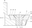
- FIG. 6 is a sectional view taken along line BB of FIG. 5.
- a chamfering machine 1 includes a tool body 10, an L-shaped guide 12 attached to the tool body 10, and a built-in tool body 10.
- a tip holding member 16 which is drivingly connected to the rotation driving unit 14 and is rotatable around a rotation center axis line R.
- the rotation driving unit 14 is an electric motor (not shown) built in the tool body 10, a first bevel gear 20 attached to an output shaft 18 of the electric motor, and a first bevel gear 20 fixed to the tip holding member 16.
- a second bevel gear 22 that meshes with.
- Cutting chips 30, 32 having different thicknesses can be selectively fixed to the chip holding member 16 as described later.
- the cutting tips 30 and 32 are held by the tip holding member 16 so that a part thereof protrudes inside the guide 12. As shown in FIG. 2, while the guide 12 is pressed against the work material W, the tip holding member 16 is rotationally driven to guide the tool body 10 in parallel with the corner E of the work material W, thereby rotating the work piece 10. The corners E are chamfered by the cutting tips 30 and 32.
- the guide 12 is attached to the tool body 10 via an eccentric ring 24 for position adjustment.
- the eccentric ring 24 is attached to the tool body 10 so as to be rotatable about the rotation center axis line R.
- the outer peripheral surface 24a of the eccentric ring 24 is eccentric with respect to the rotation center axis R, and the guide 12 is rotatably attached to the eccentric outer peripheral surface 24a. Therefore, by rotating the guide 12 with respect to the eccentric ring 24, the guide 12 is eccentric with respect to the rotation center axis R, and the position of the guide 12 with respect to the rotation center axis R can be adjusted. Thereby, the chamfering amount can be adjusted by adjusting the amount by which the cutting tips 30 and 32 project inside the guide 12.
- the guide 12 and the eccentric ring 24 can adjust the chamfering amount by the cutting tips 30 and 32 and the orientation of the tool body 10 with respect to the workpiece W.
- the chip holding member 16 is on the opposite side of the base 26 in the direction of the rotation center axis R from the shaft-shaped base 26 fixed to the second bevel gear 22 of the rotation drive unit 14. And a tip portion 28.
- a thick cutting tip (first cutting tip) 30 shown in FIGS. 4 and 5 and a thin cutting tip (second cutting tip) 32 shown in FIGS. 6 and 7 can be selectively fixed to the tip portion 28.
- the chip fixing recess 34 is provided.
- the chip fixing recess 34 is formed so as to face the rotation direction of the chip holding member 16, and has a shape that is open to the radially outer side and the tip side.
- the tip fixing recess 34 includes a seating surface 36 that engages the bottom surface (first bottom surface) 30a of the thick cutting tip 30 and the bottom surface (second bottom surface) 32a of the thin cutting tip 32, and the peripheral surface (first surface) of the thick cutting tip 30.
- the first side surface 38 engages with the peripheral surface 30b and the second side surface 40 engages with the peripheral surface (second peripheral surface) 32b of the thin cutting tip 32.
- the second side surface 40 is formed at a position projecting inside the chip fixing recess 34 with respect to the first side surface 38.
- the chip holding member 16 is provided with two chip fixing recesses 34 so that two cutting chips 30 and 32 can be attached.
- the thick cutting tip 30 has a regular pentagonal thin plate shape as a whole. More specifically, as shown in FIGS. 4 and 5, a regular pentagonal bottom surface 30a, a regular pentagonal top surface (first top surface) 30c parallel to the bottom surface 30a and larger than the bottom surface 30a, and a bottom surface 30a has a peripheral surface 30b extending outwardly from each side of the top surface 30c toward each side of the top surface 30c, and a cutting edge 30d is formed on each of the five sides between the peripheral surface 30b and the top surface 30c. ing. In addition, an insertion hole 30e that penetrates from the top surface 30c to the bottom surface 30a is formed.
- the insertion hole 30e is formed such that its central axis C1 passes through the centers of the top surface 30c and the bottom surface 30a.
- a threaded hole 41 is formed in the seating surface 36 of the chip holding member 16, and a thick cutting chip 30 is formed by screwing a flat head screw (fixing screw) 42 into the screw hole 41 through the insertion hole 30e. It is fixed in the chip fixing recess 34 of the chip holding member 16.
- a part of the cutting edge 30d formed on the peripheral edge of the top surface 30c is radially outward of the tip portion 28 and outward of the tip portion 28 toward the tip side. It will be in a protruding position.
- a part of the cutting edge 30d passes through the inside of the guide 12 when the chip holding member 16 rotates, and cuts the corner E of the work material W.
- the peripheral surface 30b of the thick cutting tip 30 has an abutting surface portion (first abutting surface portion) 30f that abuts the first side surface 38 of the tip fixing recess 34, and an inner side of the abutting surface portion 30f. It has a recessed portion 30g.
- the recess 30g is located at a position facing the second side surface 40 of the chip fixing recess 34, and has a shape adjacent to the second side surface 40 but not in contact with it. Therefore, the peripheral surface 30b of the thick cutting tip 30 contacts only the first side surface 38 of the tip fixing recess 34 and does not contact the second side surface 40 at the contact surface portion 30f.
- the peripheral surface 30b of the thick cutting tip 30 has a regular pentagonal cross section and has five plane portions 30h.
- the first side surface 38 of the tip fixing recess 34 is composed of two surfaces, and these two surfaces engage two adjacent flat surface portions 30h of the peripheral surface 30b of the thick cutting tip 30.
- the thick cutting tip 30 is fixed to the first side surface 38 by the fixing flat head screw 42 so that the peripheral surface 30b contacts the first side surface 38 of the chip fixing recess 34 when fixed by the fixing flat head screw 42. Is pressed by. Therefore, the fixed thick cutting tip 30 is in a state in which the contact surface portion 30f of the peripheral surface 30b thereof is pressed against the first side surface 38, and the first side surface 38 performs positioning in a direction parallel to the seating surface 36.
- the thin cutting tip 32 shown in FIGS. 6 and 7 also has a regular pentagonal thin plate shape as a whole. More specifically, a regular pentagonal bottom surface 32a, a regular pentagonal top surface (second top surface) 32c parallel to the bottom surface 32a and larger than the bottom surface 32a, and each side of the bottom surface 32a to the top surface 32c. It has a peripheral surface 32b that is inclined outward toward the side, and a cutting edge 32d is formed on each of the five sides between the peripheral surface 32b and the top surface 32c. An insertion hole 32e is formed so as to penetrate from the top surface 32c to the bottom surface 32a.
- the insertion hole 32e is formed so that its central axis C2 passes through the centers of the top surface 32c and the bottom surface 32a.
- the thin cutting tip 32 is also fixed to the tip fixing recess 34 of the tip holding member 16 by the fixing flat head screw 42. Since the thin cutting tip 32 is thinner than the thick cutting tip 30, the top surface 32c of the thin cutting tip 32 is smaller than the top surface 30c of the thick cutting tip 30.
- the peripheral surface 32b of the thin cutting tip 32 forms a contact surface portion (second contact surface portion) 32f that extends straight from the bottom surface 32a to the top surface 32c.
- the contact surface portion 32f of the thin cutting tip 32 is inclined at substantially the same angle as the contact surface portion 32f of the thick cutting tip 30. Since the second side surface 40 of the chip fixing recess 34 protrudes with respect to the first side surface 38, the peripheral surface 32b of the thin cutting tip 32 contacts only the second side surface 40 of the chip fixing recess 34 at the contact surface portion 32f. , Does not contact the first side surface 38.
- the peripheral surface 32b of the thin cutting tip 32 has a regular pentagonal cross section and has five plane portions 32h.
- the second side surface 40 of the tip fixing recess 34 is composed of two surfaces, and these two surfaces engage with two adjacent flat surface portions 32h of the peripheral surface 32b of the thin cutting tip 32.
- the thin cutting tip 32 is fixed to the second side surface 40 by the fixing flat head screw 42 so that the peripheral surface 32b contacts the second side surface 40 of the chip fixing recess 34 when fixed by the fixing flat head screw 42. Is pressed by. Therefore, the peripheral surface 32b of the fixed thin cutting tip 32 is pressed against the second side surface 40, and the second side surface 40 positions the thin cutting tip 32 in a direction parallel to the seating surface 36.
- the center axis C2 of the thin cutting tip 32 is Is further deviated to the side of the blade edge 32d from the central axis C3 of the fixing flat head screw 42. That is, the thin cutting tip 32 as a whole is fixed to the thick cutting tip 30 while being displaced to the side of the cutting edge 32 d protruding to the outside of the tip portion 28.
- the cutting edge 32d of the thin cutting tip 32 is thicker. It is located rearward of the blade edge 30d of 30 in the rotational direction. Since the positions of the cutting edges 30d and 32d in the rotation direction are different, the angles of the cutting edges 30d and 32d when the cutting edges 30d and 32d hit the work material W at the deepest position, that is, the cutting edge contact angles are different. Become.
- the thick cutting tip 30 having the cutting edge 30d in the front in the rotation direction is the position where the cutting edge 30d most deeply hits the work material W with a smaller rotation amount, and has the thin cutting edge 32d in the rear in the rotation direction.
- the cutting tip 32 reaches a position where the cutting edge 32d hits the work W most deeply with a larger amount of rotation. Therefore, the blade tip contact angle ⁇ of the thick cutting tip 30 becomes smaller than the blade tip contact angle ⁇ of the thin cutting tip 32. That is, the blade contact angle can be changed by using cutting tips having different thicknesses.
- the chamfering amount adjusted by the eccentric ring 24 is changed by exchanging the cutting tip.
- the thin cutting tip 32 is positioned by the second side surface 40 located at a position projecting toward the cutting edge 32d side from the first side surface 38 as described above.
- the thin cutting tip 32 has a central axis C2 protruding to the outside of the tip end portion 28 with respect to the central axis C1 of the thick cutting tip 30 by an amount corresponding to the second side surface 40 protruding from the first side surface 38. It is fixed at a position displaced to the side of the cutting edge 32d that is present. That is, the cutting edge 32d of the thin cutting tip 32 is displaced to the side of the corner E of the workpiece W by the amount that the second side surface 40 projects toward the cutting edge 32d side with respect to the first side surface 38. Become.
- the circular trajectory T1 drawn by the cutting edge 30d of the thick cutting tip 30 and the circular trajectory T2 drawn by the thin cutting tip 32 are substantially coincident with each other. It is supposed to do.
- the first side surface 38 and the second side surface 40 are shaped so that the circular locus T1 drawn by the cutting edge 30d of the thick cutting tip 30 and the circular locus T2 drawn by the cutting edge 32d of the thin cutting tip 32 substantially match. It is attached.
- the blade tip contact angle can be changed by simply exchanging the cutting tips 30 and 32. Furthermore, even if the thick cutting tip 30 and the thin cutting tip 32 are exchanged, the trajectories T1 and T2 drawn by the respective cutting edges 30d and 32d are substantially the same, so the cutting tips 30 and 32 are exchanged. Sometimes it is not necessary to readjust the chamfering amount by the eccentric ring 24.
- an inclined surface 130i inclined from the cutting edge 130d toward the center of the top surface 130c on the opposite side of the bottom surface 130a is formed.
- the shape of the cutting tip is not limited to a regular pentagon, and may be another regular polygon such as a regular triangle or a square.
- a regular polygonal shape By forming the cutting tip into a regular polygonal shape, a plurality of cutting edges are formed, and even if one cutting edge is worn, another cutting edge can be used by rotating the cutting tip and reattaching it Many chamfering operations can be performed on the tip.
- the shape of the cutting tip may be other than a regular polygon, such as a parallelogram.
- the cutting edge of the cutting tip is linearly formed so as to chamfer the corner portion of the work material at 45°, but the chamfering is performed at an angle other than 45°.
- the angle of the cutting edge may be changed or the fixing angle of the cutting tip may be changed, or the cutting edge may be curved so as to perform a rounded R chamfer.
- two types of cutting tips having different thicknesses can be used, but more cutting tips having different thicknesses can be used by forming the side surface of the tip fixing recessed portion into three or more steps. You can also allow it.
- the seating surface of the tip fixing recess may be a surface inclined with respect to the rotation center axis so that the cutting tip is attached obliquely with respect to the rotation center axis.
- the tool body is guided by the L-shaped guide in parallel with the linearly extending corners of the work material, but other types of guides such as guide rollers are used. Then, the tool body is guided along the curved extending corners such as the corners of the curved groove and the inner circumference of the hole, and the chamfering of the curved corners is performed. It may be a machine.
Landscapes
- Engineering & Computer Science (AREA)
- Mechanical Engineering (AREA)
- Milling Processes (AREA)
Abstract
【課題】チップ保持部材を交換することなく刃先接触角を変更することを可能とする面取り機を提供する。 【解決手段】当該面取り機1におけるチップ保持部材16は、その先端部28に厚い切削チップ30と薄い切削チップ32とを選択的に固定可能なチップ固定凹部34を有する。チップ固定凹部34は、厚い切削チップ30の周面30bに係合する第1側面38と、薄い切削チップ32の周面32bに係合する第2側面40を有する。第2側面40は、薄い切削チップ32の刃先32dが先端部28の外側に突出する側に、第1側面38に対して突出して形成されている。厚さの異なる切削チップ30、32に交換することによって回転方向での刃先の位置が変わり刃先接触角を変更できる。また薄い切削チップ32は第2側面40により刃先32dの側にずれた位置で固定されて、その刃先32dの軌跡T2と厚い切削チップ30の刃先30dの軌跡T2を略同一となる。
Description
本発明は、切削チップを回転させながら工具本体を被削材の角部に並行して案内することで切削チップにより角部の面取りを行うようにした面取り機、そのような面取り機において切削チップを保持して回転駆動されるチップ保持部材、およびチップ保持部材に保持される切削チップに関する。
例えば特許文献1に示されるように、面取り機は、モータを内蔵する工具本体と、モータに駆動連結されて回転駆動されるチップ保持部材(刃物支持体)と、被削材上に載せられて被削材に対する工具本体の相対位置を保持するためのガイドと、を備える。チップ保持部材には所定の切削チップが固定され、チップ保持部材が回転中心軸線を中心として回転駆動されることにより、切削チップも回転中心軸線を中心に回転される。このような面取り機は、切削チップを回転させながら、工具本体を被削材の角部に並行して案内することにより、切削チップが被削材の角部を切削して面取り加工が行われるようになっている。
切削チップは、頂面と傾斜した周面との間に刃先を有しており、この刃先が被削材に対して最も深い位置で当たるときの被削材に対する頂面の角度(以下、刃先接触角という)が刃先の寿命に大きく影響することが知られている。例えば、鉄材を面取りするときに最適な刃先接触角は、ステンレス材を面取りするときに最適な刃先接触角よりも小さい。そのため、被削材の材質に合わせて切削チップの刃先接触角を変えることが望ましい。
切削チップの刃先接触角は、切削チップがチップ保持部材上にどのような位置と姿勢で取り付けられるのかによって決まる。すなわち、チップ保持部材に設けられたチップ固定凹部の形状によって決まる。そのため、従来の面取り機においては、刃先接触角を変更するためには、チップ保持部材を交換する必要があった。しかしながら、チップ保持部材を交換するためには工具本体の一部を分解する必要があり、その交換作業は繁雑であった。
そこで本発明は、チップ保持部材を交換することなく刃先接触角を変更することが可能となる面取り機、該面取り機におけるチップ保持部材、及び該チップ保持部材に固定される切削チップを提供することを目的とする。
すなわち本発明は、
切削チップを回転させながら工具本体を被削材の角部に沿って案内することで前記切削チップにより前記角部の面取りを行うようにされた面取り機において、前記切削チップを保持し、前記工具本体の回転駆動部に駆動連結されて回転中心軸線を中心に回転駆動されるチップ保持部材であって、
面取り機の回転駆動部に駆動連結される基部と、前記回転中心軸線の方向で前記基部の反対側にある先端部とを備え、
前記先端部が、頂面の周縁に刃先を有する第1切削チップと、頂面の周縁に刃先を有し前記第1切削チップよりも薄い第2切削チップとを、前記刃先の少なくとも一部が当該先端部の外側に突出して被削材の角部に係合可能となるように、選択的に固定するチップ固定凹部を有し、
前記チップ固定凹部は、当該チップ保持部材の回転方向に面して前記第1及び第2切削チップの底面と係合する着座面と、前記第1切削チップの周面に係合して前記着座面に平行な方向での前記第1切削チップの位置決めを行う第1側面と、前記第2切削チップの周面に係合して前記着座面に平行な方向での前記第2切削チップの位置決めを行う第2側面とを有し、前記チップ固定凹部に固定されたときの、前記第2切削チップの刃先が、前記第1切削チップの刃先よりも前記回転方向での後方に位置するようにされ、
前記第2側面が、前記刃先の前記少なくとも一部が前記先端部の外側に突出する側に、前記第1側面に対して突出して形成されている、チップ保持部材を提供する。
切削チップを回転させながら工具本体を被削材の角部に沿って案内することで前記切削チップにより前記角部の面取りを行うようにされた面取り機において、前記切削チップを保持し、前記工具本体の回転駆動部に駆動連結されて回転中心軸線を中心に回転駆動されるチップ保持部材であって、
面取り機の回転駆動部に駆動連結される基部と、前記回転中心軸線の方向で前記基部の反対側にある先端部とを備え、
前記先端部が、頂面の周縁に刃先を有する第1切削チップと、頂面の周縁に刃先を有し前記第1切削チップよりも薄い第2切削チップとを、前記刃先の少なくとも一部が当該先端部の外側に突出して被削材の角部に係合可能となるように、選択的に固定するチップ固定凹部を有し、
前記チップ固定凹部は、当該チップ保持部材の回転方向に面して前記第1及び第2切削チップの底面と係合する着座面と、前記第1切削チップの周面に係合して前記着座面に平行な方向での前記第1切削チップの位置決めを行う第1側面と、前記第2切削チップの周面に係合して前記着座面に平行な方向での前記第2切削チップの位置決めを行う第2側面とを有し、前記チップ固定凹部に固定されたときの、前記第2切削チップの刃先が、前記第1切削チップの刃先よりも前記回転方向での後方に位置するようにされ、
前記第2側面が、前記刃先の前記少なくとも一部が前記先端部の外側に突出する側に、前記第1側面に対して突出して形成されている、チップ保持部材を提供する。
当該チップ保持部材においては、厚さの異なる第1切削チップと第2切削チップとを選択的に固定可能となっており、切削チップを交換することによって刃先の位置が回転方向での前後で変わるようになっている。これにより、刃先が被削材に接触するときの角度(刃先接触角)を変更することができる。ここで、単に厚さの異なる切削チップに交換した場合には、回転方向での刃先の位置だけでなく回転中心軸線から刃先までの距離も変わってしまい、それによって面取り量も大きく変わってしまう。これに対して当該チップ保持部材においては、厚い第1切削チップと薄い第2切削チップがそれぞれ異なる側面により位置決めされるようになっており、第2切削チップは厚い第1切削チップに比べて刃先が先端部の外側に突出する側にずれた位置で固定されるようになっている。これにより、切削チップを交換した際の回転中心軸線から刃先までの距離の変化量を小さくして、切削チップを交換したときの面取り量のずれを小さくすることが可能となる。
好ましくは、当該チップ保持部材が回転されたときに、前記チップ固定凹部に固定された前記第1切削チップの前記先端部の外側に突出した刃先の部分が描く円形の軌跡と、前記チップ固定凹部に固定された前記第2切削チップの前記先端部の外側に突出した刃先の部分が描く円形の軌跡とが略一致するように、前記第1及び第2側面が形状付けられているようにすることができる。
このような構成により、切削チップを交換しても面取り量が変わらなくなり、切削チップの交換時に面取り量の調整を再度行う必要がなくなる。
また、前記第1及び第2切削チップのそれぞれが前記頂面から前記底面に貫通する挿通孔を有しており、
前記着座面は前記第1及び第2切削チップの前記挿通孔を通された固定用ネジが螺合されるネジ穴を有し、前記固定用ネジが前記挿通孔を通して前記ネジ穴に螺合されたときに、前記固定用ネジによって前記第1及び第2切削チップがそれぞれ前記第1及び第2側面に押圧された状態で前記チップ固定凹部に固定されるようにすることができる。
前記着座面は前記第1及び第2切削チップの前記挿通孔を通された固定用ネジが螺合されるネジ穴を有し、前記固定用ネジが前記挿通孔を通して前記ネジ穴に螺合されたときに、前記固定用ネジによって前記第1及び第2切削チップがそれぞれ前記第1及び第2側面に押圧された状態で前記チップ固定凹部に固定されるようにすることができる。
また、前記第1及び第2切削チップの前記頂面と前記底面が正多角形状であり、前記挿通孔の中心軸線が前記頂面と前記底面の中心を通るように前記第1及び第2切削チップの前記挿通孔が形成されており、
前記チップ固定凹部に固定されたときの前記第2切削チップの前記挿通孔の中心軸線が、前記チップ固定凹部に固定されたときの前記第1切削チップの前記挿通孔の中心軸線よりも、前記先端部の外側に突出した刃先の部分の側に前記固定用ネジの中心軸線から大きくずれた位置となるように、前記第1及び第2側面が形状付けられているようにすることができる。
前記チップ固定凹部に固定されたときの前記第2切削チップの前記挿通孔の中心軸線が、前記チップ固定凹部に固定されたときの前記第1切削チップの前記挿通孔の中心軸線よりも、前記先端部の外側に突出した刃先の部分の側に前記固定用ネジの中心軸線から大きくずれた位置となるように、前記第1及び第2側面が形状付けられているようにすることができる。
このような構成とすることにより、1つの切削チップで複数の刃先を得られ、切削チップを回転させて取り付けることにより、刃先の位置を変えずに新たな刃先で面取り加工を行うことが可能となる。
さらには、前記第1及び第2切削チップの周面が、正多角形状の横断面を有し、且つ複数の平面部分を有しており、
前記チップ固定凹部の前記第1及び第2側面は、前記第1及び第2切削チップの前記周面における少なくとも2つの平面部分に係合するようにすることができる。
前記チップ固定凹部の前記第1及び第2側面は、前記第1及び第2切削チップの前記周面における少なくとも2つの平面部分に係合するようにすることができる。
このような構成により、切削チップの着座面に平行な方向での位置決めをより安定して行うことが可能となる。
また本発明は、上述のいずれかのチップ保持部材を備える面取り機を提供することを目的とする。
さらに本発明は、上述のいずれかのチップ保持部材に固定される切削チップであって、前記着座面に係合する底面、前記底面と平行な頂面、及び前記底面から前記頂面に向かって当該切削チップの外側に傾斜して延びて前記頂面との間に刃先を形成する周面を有し、前記周面が、前記チップ保持部材の前記第1側面に当接する当接面部、及び前記チップ保持部材の前記第2側面に面する位置で前記第2側面に接触しないように窪んだ凹部を有する、切削チップを提供する。
さらに本発明は、上述のいずれかのチップ保持部材に固定される第1及び第2切削チップを含む一組の切削チップであって、
前記第1切削チップが、前記着座面に係合する第1底面、前記第1底面と平行な第1頂面、及び前記第1底面から前記第1頂面に向かって当該第1切削チップの外側に傾斜して延びて前記第1頂面との間に刃先を形成する第1周面を有し、前記第1周面が、前記チップ保持部材の前記第1側面に当接する第1当接面部、及び前記チップ保持部材の前記第2側面に面する位置で前記第2側面に接触しないように窪んだ凹部を有し、
前記第2切削チップが、前記着座面に係合する第2底面、前記第2底面と平行な第2頂面、及び前記第2底面から前記第2頂面に向かって当該第2切削チップの外側に傾斜して延びて前記第2頂面との間に刃先を形成する第2周面を有し、前記第2周面が、前記第1切削チップの前記第1当接面部と略同角度で傾斜して前記チップ保持部材の前記第2側面に当接する第2当接面部を有し、
前記第2切削チップが前記第1切削チップよりも薄く、前記第2頂面が前記第1頂面よりも小さい、一組の切削チップを提供する。
前記第1切削チップが、前記着座面に係合する第1底面、前記第1底面と平行な第1頂面、及び前記第1底面から前記第1頂面に向かって当該第1切削チップの外側に傾斜して延びて前記第1頂面との間に刃先を形成する第1周面を有し、前記第1周面が、前記チップ保持部材の前記第1側面に当接する第1当接面部、及び前記チップ保持部材の前記第2側面に面する位置で前記第2側面に接触しないように窪んだ凹部を有し、
前記第2切削チップが、前記着座面に係合する第2底面、前記第2底面と平行な第2頂面、及び前記第2底面から前記第2頂面に向かって当該第2切削チップの外側に傾斜して延びて前記第2頂面との間に刃先を形成する第2周面を有し、前記第2周面が、前記第1切削チップの前記第1当接面部と略同角度で傾斜して前記チップ保持部材の前記第2側面に当接する第2当接面部を有し、
前記第2切削チップが前記第1切削チップよりも薄く、前記第2頂面が前記第1頂面よりも小さい、一組の切削チップを提供する。
以下、本発明に係る面取り機の実施形態を添付図面に基づき説明する。
本発明の一実施形態に係る面取り機1は、図1及び図2に示すように、工具本体10と、工具本体10に取り付けられたL字状のガイド12と、工具本体10に内蔵された回転駆動部14に駆動連結されて回転中心軸線Rを中心に回転可能とされたチップ保持部材16と、を備える。回転駆動部14は、工具本体10内に内蔵された(図示しない)電動モータと、電動モータの出力軸18に取り付けられた第1ベベルギア20と、チップ保持部材16に固定されて第1ベベルギア20と噛み合う第2ベベルギア22とを有する。チップ保持部材16には、後述するように厚さの異なる切削チップ30、32を選択的に固定できるようになっている。切削チップ30、32は、その一部がガイド12の内側に突出するようにしてチップ保持部材16に保持される。図2に示すようにガイド12を被削材Wに押し当てた状態でチップ保持部材16を回転駆動して工具本体10を被削材Wの角部Eに並行して案内することによって、回転する切削チップ30、32により角部Eの面取り加工が行われるようになっている。
図1に示すように、ガイド12は位置調整用の偏心リング24を介して工具本体10に取り付けられている。偏心リング24は、工具本体10に対して回転中心軸線Rを中心として回転可能に取付けられている。偏心リング24の外周面24aは回転中心軸線Rに対して偏心しており、ガイド12はこの偏心した外周面24aに回転可能に取り付けられている。そのため、ガイド12を偏心リング24に対して回転させることにより、ガイド12は回転中心軸線Rに対して偏心して、回転中心軸線Rに対するガイド12の位置を調節できる。これにより、切削チップ30、32がガイド12の内側に突出する量を調節して、面取り量を調節することができる。また、ガイド12と共に偏心リング24を回転させることにより、回転中心軸線Rに対するガイド12の位置を変えずに工具本体10に対するガイド12の向きのみを変更することもできる。すなわち、ガイド12と偏心リング24とによって、切削チップ30、32による面取り量と、被削材Wに対する工具本体10の向きを調整することができる。
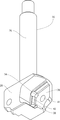
チップ保持部材16は、図2及び図3に示すように、回転駆動部14の第2ベベルギア22に固定される軸状の基部26と、回転中心軸線Rの方向で基部26の反対側にある先端部28とを備える。先端部28には、図4及び図5に示す厚い切削チップ(第1切削チップ)30と、図6及び図7に示す薄い切削チップ(第2切削チップ)32とを選択的に固定可能とされたチップ固定凹部34が設けられている。チップ固定凹部34は、チップ保持部材16の回転方向に面して形成され、径方向外側及び先端側に開口した形状となっている。チップ固定凹部34は、厚い切削チップ30の底面(第1底面)30aと薄い切削チップ32の底面(第2底面)32aに係合する着座面36と、厚い切削チップ30の周面(第1周面)30bに係合する第1側面38と、薄い切削チップ32の周面(第2周面)32bに係合する第2側面40とを有する。第2側面40は、第1側面38に対して、チップ固定凹部34の内側に突出した位置に形成されている。なお、チップ保持部材16には、チップ固定凹部34が2つ設けられており、切削チップ30、32を2つ取り付けられるようになっている。
厚い切削チップ30は、全体として正五角形の薄板形状を有している。より具体的には、図4及び図5に示すように、正五角形状の底面30aと、底面30aと平行で底面30aよりも大きい正五角形状の頂面(第1頂面)30cと、底面30aの各辺から頂面30cの各辺に向かって外側に傾斜して延びる周面30bとを有し、周面30bと頂面30cとの間の5つの辺のそれぞれに刃先30dが形成されている。また、頂面30cから底面30aに貫通した挿通孔30eが形成されている。挿通孔30eは、その中心軸線C1が頂面30cと底面30aの中心を通るように形成されている。チップ保持部材16の着座面36には、ネジ穴41が形成されており、挿通孔30eを通して固定用皿ネジ(固定用ネジ)42をネジ穴41に螺合することにより、厚い切削チップ30はチップ保持部材16のチップ固定凹部34に固定される。厚い切削チップ30は、チップ固定凹部34に固定されると、頂面30cの周縁に形成された刃先30dの一部が先端部28の径方向外側且つ先端側に向かって先端部28の外側に突出した位置となる。この刃先30dの一部は、チップ保持部材16が回転したときにガイド12の内側を通過し、被削材Wの角部Eを切削する。
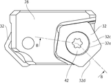
厚い切削チップ30の周面30bは、図5に示すように、チップ固定凹部34の第1側面38に当接する当接面部(第1当接面部)30fと、この当接面部30fよりも内側に窪んだ凹部30gとを有する。凹部30gは、チップ固定凹部34の第2側面40に面する位置にあり、第2側面40に隣接はするが接触はしない形状となっている。従って、厚い切削チップ30の周面30bは、当接面部30fにおいてチップ固定凹部34の第1側面38にのみ接触し、第2側面40には接触しない。厚い切削チップ30の周面30bは、正五角形状の横断面を有し、且つ5つの平面部分30hを有する。チップ固定凹部34の第1側面38は2つの面で構成されており、この2つの面で厚い切削チップ30の周面30bの隣り合う2つの平面部分30hに係合するようになっている。厚い切削チップ30は、固定用皿ネジ42によって固定されるときに、その周面30bがチップ固定凹部34の第1側面38に接触するように、固定用皿ネジ42によって第1側面38の側に押圧される。そのため、固定された厚い切削チップ30はその周面30bの当接面部30fが第1側面38に押し付けられた状態となり、第1側面38によって着座面36に平行な方向での位置決めがなされる。
図6及び図7に示す薄い切削チップ32も同様に、全体として正五角形の薄板形状を有している。より具体的には、正五角形状の底面32aと、底面32aと平行で底面32aよりも大きい正五角形状の頂面(第2頂面)32cと、底面32aの各辺から頂面32cの各辺に向かって外側に傾斜して延びる周面32bとを有し、周面32bと頂面32cとの間の5つの辺のそれぞれに刃先32dが形成されている。また、頂面32cから底面32aに貫通した挿通孔32eが形成されている。挿通孔32eは、その中心軸線C2が頂面32cと底面32aの中心を通るように形成されている。薄い切削チップ32も固定用皿ネジ42によってチップ保持部材16のチップ固定凹部34に固定される。薄い切削チップ32は厚い切削チップ30よりも薄いため、薄い切削チップ32の頂面32cは厚い切削チップ30の頂面30cよりも小さい。
薄い切削チップ32の周面32bは、図7に示すように、底面32aから頂面32cにまで真っ直ぐに延びた当接面部(第2当接面部)32fを形成している。薄い切削チップ32の当接面部32fは厚い切削チップ30の当接面部32fと略同角度で傾斜している。チップ固定凹部34の第2側面40は第1側面38に対して突出しているため、薄い切削チップ32の周面32bは、当接面部32fにおいてチップ固定凹部34の第2側面40にのみ接触し、第1側面38には接触しない。薄い切削チップ32の周面32bは、正五角形状の横断面を有し、且つ5つの平面部分32hを有する。チップ固定凹部34の第2側面40は2つの面で構成されており、この2つの面が薄い切削チップ32の周面32bの隣り合う2つの平面部分32hに係合するようになっている。薄い切削チップ32は、固定用皿ネジ42によって固定されるときに、その周面32bがチップ固定凹部34の第2側面40に接触するように、固定用皿ネジ42によって第2側面40の側に押圧される。そのため、固定された薄い切削チップ32はその周面32bが第2側面40に押し付けられた状態となり、第2側面40によって着座面36に平行な方向での位置決めがなされる。
チップ固定凹部34に固定された厚い切削チップ30の挿通孔30eの中心軸線C1と薄い切削チップ32の挿通孔32eの中心軸線C2との位置を比較すると、薄い切削チップ32の中心軸線C2の方が刃先32dの側に固定用皿ネジ42の中心軸線C3からより大きくずれている。すなわち、薄い切削チップ32は厚い切削チップ30に対して全体として、先端部28の外側に突出している刃先32dの側にずれて固定される。
図8に示すように、チップ保持部材16に固定されたときの、厚い切削チップ30の刃先30dと薄いチップの刃先32dの位置を比較すると、薄い切削チップ32の刃先32dの方が厚い切削チップ30の刃先30dよりも回転方向での後方に位置することになる。回転方向での刃先30d、32dの位置が異なることにより、回転して刃先30d、32dが被削材Wに最も深い位置で当たるときの刃先30d、32dの角度、すなわち刃先接触角が異なるようになる。具体的には、回転方向で前方に刃先30dを有する厚い切削チップ30は、より少ない回転量でその刃先30dが被削材Wに最も深く当たる位置となり、回転方向で後方に刃先32dを有する薄い切削チップ32はより多い回転量でその刃先32dが被削材Wに最も深く当たる位置となる。そのため厚い切削チップ30の刃先接触角αは薄い切削チップ32の刃先接触角βよりも小さくなる。すなわち、厚さの異なる切削チップを用いることにより刃先接触角を変更することができる。ただし、厚さを薄くすることにより刃先の位置を回転方向での後方とすると、それと同時に回転中心軸線Rから刃先までの距離が短くなり、刃先が被削材Wに当たる深さも変わる。そうすると、偏心リング24により調整した面取り量が切削チップの交換により変わってしまう。当該面取り機1においては、薄い切削チップ32は、上述の様に第1側面38よりも刃先32dの側に突出した位置にある第2側面40によって位置決めされるようになっている。そのため、薄い切削チップ32は、第2側面40が第1側面38に対して突出している分だけ、その中心軸線C2が厚い切削チップ30の中心軸線C1に対して先端部28の外側に突出している刃先32dの部分の側にずれた位置で固定される。すなわち、薄い切削チップ32の刃先32dは、第2側面40が第1側面38に対してこの刃先32dの側に突出している分だけ、被削材Wの角部Eの側にずれた位置となる。これにより、当該面取り機1においては、チップ保持部材16が回転されたときに、厚い切削チップ30の刃先30dが描く円形の軌跡T1と、薄い切削チップ32が描く円形の軌跡T2とが略一致するようになっている。換言すれば、第1側面38と第2側面40は、厚い切削チップ30の刃先30dが描く円形の軌跡T1と薄い切削チップ32の刃先32dが描く円形の軌跡T2とが略一致するように形状付けられている。
このように、当該面取り機1においては、単に切削チップ30,32を交換するだけで刃先接触角を変更することができる。さらには、厚い切削チップ30と薄い切削チップ32とを交換しても各刃先30d、32dが描く軌跡T1、T2が実質的に一致するようになっているため、切削チップ30、32を交換したときに偏心リング24により面取り量を再度調整する必要がない。
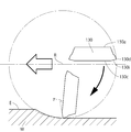
別の実施形態に係る厚い切削チップ130においては、図9に示すように、刃先130dから頂面130cの中心に向かって底面130aの反対側に傾斜した傾斜面130iが形成されている。このような傾斜面130iを設けることで、刃先接触角γを上述の厚い切削チップ30の刃先接触角α及び薄い切削チップ32の刃先接触角βに比べてさらに小さくすることが可能となる。
以上に本発明の実施形態について説明をしたが、本発明はこれら実施形態に限定されるものではない。例えば、切削チップの形状は、正五角形に限らず、正三角形や正方形などの他の正多角形状としてもよい。切削チップを正多角形状とすることにより、複数の刃先が形成され、1つの刃先が摩耗しても切削チップを回転させて再度取り付けることにより他の刃先を利用することができるため、1つの切削チップで多くの面取り加工を行うことができる。または、切削チップの形状を正多角形ではない、平行四辺形などの他の形状とすることも可能である。さらには上記実施形態においては、切削チップの刃先が被削材の角部を45°でC面取りするように直線的に形成されているが、45°以外の角度での直線的な面取りを行うように刃先の角度を変えるか又は切削チップの固定角度を変えてもよいし、又は丸いR面取りを行うように刃先を湾曲したものとしてもよい。上記実施形態においては厚さの異なる2種類の切削チップを使用できるようになっているが、チップ固定凹部の側面を3段以上にするなどして、より多くの厚さの異なる切削チップを使用できるようにすることもできる。さらには、チップ固定凹部の着座面を回転中心軸線に対して傾斜した面にして、切削チップが回転中心軸線に対して斜めに取り付けられるようにしてもよい。上記実施形態においては、L字状のガイドによって被削材の直線状に延びる角部に並行して工具本体を案内するようになっているが、ガイドローラのような他の形態のガイドを利用して、曲がった溝の角部や孔の内周の角部などのような湾曲して延びる角部に沿って工具本体を案内して、湾曲した角部の面取り加工を行うようにした面取り機としてもよい。
1 面取り機
10 工具本体
12 ガイド
14 回転駆動部
16 チップ保持部材
18 出力軸
20 第1ベベルギア
22 第2ベベルギア
24 偏心リング
24a 外周面
26 基部
28 先端部
30 切削チップ(第1切削チップ)
30a 底面(第1底面)
30b 周面(第1周面)
30c 頂面(第1頂面)
30d 刃先
30e 挿通孔
30f 当接面部(第1当接面部)
30g 凹部
30h 平面部分
32 切削チップ(第2切削チップ)
32a 底面(第2底面)
32b 周面(第2周面)
32c 頂面(第2頂面)
32d 刃先
32e 挿通孔
32f 当接面部(第2当接面部)
32h 平面部分
34 チップ固定凹部
36 着座面
38 第1側面
40 第2側面
41 ネジ穴
42 固定用皿ネジ(固定用ネジ)
130 切削チップ
130a 底面
130c 頂面
130d 刃先
130i 傾斜面
C1、C2、C3 中心軸線
R 回転中心軸線
T1、T2 軌跡
W 被削材
E 角部
α、β、γ 刃先接触角
10 工具本体
12 ガイド
14 回転駆動部
16 チップ保持部材
18 出力軸
20 第1ベベルギア
22 第2ベベルギア
24 偏心リング
24a 外周面
26 基部
28 先端部
30 切削チップ(第1切削チップ)
30a 底面(第1底面)
30b 周面(第1周面)
30c 頂面(第1頂面)
30d 刃先
30e 挿通孔
30f 当接面部(第1当接面部)
30g 凹部
30h 平面部分
32 切削チップ(第2切削チップ)
32a 底面(第2底面)
32b 周面(第2周面)
32c 頂面(第2頂面)
32d 刃先
32e 挿通孔
32f 当接面部(第2当接面部)
32h 平面部分
34 チップ固定凹部
36 着座面
38 第1側面
40 第2側面
41 ネジ穴
42 固定用皿ネジ(固定用ネジ)
130 切削チップ
130a 底面
130c 頂面
130d 刃先
130i 傾斜面
C1、C2、C3 中心軸線
R 回転中心軸線
T1、T2 軌跡
W 被削材
E 角部
α、β、γ 刃先接触角
Claims (8)
- 切削チップを回転させながら工具本体を被削材の角部に沿って案内することで前記切削チップにより前記角部の面取りを行うようにされた面取り機において、前記切削チップを保持し、前記工具本体の回転駆動部に駆動連結されて回転中心軸線を中心に回転駆動されるチップ保持部材であって、
面取り機の回転駆動部に駆動連結される基部と、前記回転中心軸線の方向で前記基部の反対側にある先端部とを備え、
前記先端部が、頂面の周縁に刃先を有する第1切削チップと、頂面の周縁に刃先を有し前記第1切削チップよりも薄い第2切削チップとを、前記刃先の少なくとも一部が当該先端部の外側に突出して被削材の角部に係合可能となるように、選択的に固定するチップ固定凹部を有し、
前記チップ固定凹部は、当該チップ保持部材の回転方向に面して前記第1及び第2切削チップの底面と係合する着座面と、前記第1切削チップの周面に係合して前記着座面に平行な方向での前記第1切削チップの位置決めを行う第1側面と、前記第2切削チップの周面に係合して前記着座面に平行な方向での前記第2切削チップの位置決めを行う第2側面とを有し、前記チップ固定凹部に固定されたときの、前記第2切削チップの刃先が、前記第1切削チップの刃先よりも前記回転方向での後方に位置するようにされ、
前記第2側面が、前記刃先の前記少なくとも一部が前記先端部の外側に突出する側に、前記第1側面に対して突出して形成されている、チップ保持部材。 - 当該チップ保持部材が回転されたときに、前記チップ固定凹部に固定された前記第1切削チップの前記先端部の外側に突出した刃先の部分が描く円形の軌跡と、前記チップ固定凹部に固定された前記第2切削チップの前記先端部の外側に突出した刃先の部分が描く円形の軌跡とが略一致するように、前記第1及び第2側面が形状付けられている、請求項1に記載のチップ保持部材。
- 前記第1及び第2切削チップのそれぞれが前記頂面から前記底面に貫通する挿通孔を有しており、
前記着座面は前記第1及び第2切削チップの前記挿通孔を通された固定用ネジが螺合されるネジ穴を有し、前記固定用ネジが前記挿通孔を通して前記ネジ穴に螺合されたときに、前記固定用ネジによって前記第1及び第2切削チップがそれぞれ前記第1及び第2側面に押圧された状態で前記チップ固定凹部に固定されるようにされた、請求項1又は2に記載のチップ保持部材。 - 前記第1及び第2切削チップの前記頂面と前記底面が正多角形状であり、前記挿通孔の中心軸線が前記頂面と前記底面の中心を通るように前記第1及び第2切削チップの前記挿通孔が形成されており、
前記チップ固定凹部に固定されたときの前記第2切削チップの前記挿通孔の中心軸線が、前記チップ固定凹部に固定されたときの前記第1切削チップの前記挿通孔の中心軸線よりも、前記先端部の外側に突出した刃先の部分の側に前記固定用ネジの中心軸線から大きくずれた位置となるように、前記第1及び第2側面が形状付けられている、請求項3に記載のチップ保持部材。 - 前記第1及び第2切削チップの周面が、正多角形状の横断面を有し、且つ複数の平面部分を有しており、
前記チップ固定凹部の前記第1及び第2側面は、前記第1及び第2切削チップの前記周面における少なくとも2つの平面部分に係合するようにされている、請求項1乃至4のいずれか一項に記載のチップ保持部材。 - 請求項1乃至5のいずれか一項に記載のチップ保持部材を備える面取り機。
- 請求項1乃至5のいずれか一項に記載のチップ保持部材に固定される切削チップであって、前記着座面に係合する底面、前記底面と平行な頂面、及び前記底面から前記頂面に向かって当該切削チップの外側に傾斜して延びて前記頂面との間に刃先を形成する周面を有し、前記周面が、前記チップ保持部材の前記第1側面に当接する当接面部、及び前記チップ保持部材の前記第2側面に面する位置で前記第2側面に接触しないように窪んだ凹部を有する、切削チップ。
- 請求項1乃至5のいずれか一項に記載のチップ保持部材に固定される第1及び第2切削チップを含む一組の切削チップであって、
前記第1切削チップが、前記着座面に係合する第1底面、前記第1底面と平行な第1頂面、及び前記第1底面から前記第1頂面に向かって当該第1切削チップの外側に傾斜して延びて前記第1頂面との間に刃先を形成する第1周面を有し、前記第1周面が、前記チップ保持部材の前記第1側面に当接する第1当接面部、及び前記チップ保持部材の前記第2側面に面する位置で前記第2側面に接触しないように窪んだ凹部を有し、
前記第2切削チップが、前記着座面に係合する第2底面、前記第2底面と平行な第2頂面、及び前記第2底面から前記第2頂面に向かって当該第2切削チップの外側に傾斜して延びて前記第2頂面との間に刃先を形成する第2周面を有し、前記第2周面が、前記第1切削チップの前記第1当接面部と略同角度で傾斜して前記チップ保持部材の前記第2側面に当接する第2当接面部を有し、
前記第2切削チップが前記第1切削チップよりも薄く、前記第2頂面が前記第1頂面よりも小さい、一組の切削チップ。
Priority Applications (1)
| Application Number | Priority Date | Filing Date | Title |
|---|---|---|---|
| JP2020563057A JP7076013B2 (ja) | 2018-12-26 | 2019-12-12 | チップ保持部材、面取り機、および切削チップ |
Applications Claiming Priority (2)
| Application Number | Priority Date | Filing Date | Title |
|---|---|---|---|
| JP2018242814 | 2018-12-26 | ||
| JP2018-242814 | 2018-12-26 |
Publications (1)
| Publication Number | Publication Date |
|---|---|
| WO2020137571A1 true WO2020137571A1 (ja) | 2020-07-02 |
Family
ID=71127160
Family Applications (1)
| Application Number | Title | Priority Date | Filing Date |
|---|---|---|---|
| PCT/JP2019/048630 Ceased WO2020137571A1 (ja) | 2018-12-26 | 2019-12-12 | チップ保持部材、面取り機、および切削チップ |
Country Status (3)
| Country | Link |
|---|---|
| JP (1) | JP7076013B2 (ja) |
| TW (1) | TWI724688B (ja) |
| WO (1) | WO2020137571A1 (ja) |
Citations (5)
| Publication number | Priority date | Publication date | Assignee | Title |
|---|---|---|---|---|
| JPH08243828A (ja) * | 1995-03-08 | 1996-09-24 | Komatsu Ltd | 可搬式自動面取り装置のr面取りカッタ |
| JP2007229857A (ja) * | 2006-02-28 | 2007-09-13 | Kyocera Corp | スローアウェイチップおよび回転切削工具 |
| JP2010179409A (ja) * | 2009-02-05 | 2010-08-19 | Jtekt Corp | 切削工具 |
| JP2012206243A (ja) * | 2011-03-30 | 2012-10-25 | Hitachi Ltd | フライス工具 |
| CN206083961U (zh) * | 2016-08-31 | 2017-04-12 | 成都晶脉精密机械有限公司 | 一种加工纤维复合材料的不等倾角pcd铣刀 |
Family Cites Families (4)
| Publication number | Priority date | Publication date | Assignee | Title |
|---|---|---|---|---|
| IL148535A (en) * | 2002-03-06 | 2009-02-11 | Gil Hecht | Metal cutting tool |
| SE535147C2 (sv) * | 2009-12-18 | 2012-04-24 | Sandvik Intellectual Property | Anordning för fräsning av material |
| CN102029421B (zh) * | 2010-12-16 | 2013-03-06 | 保定天威集团有限公司 | 成型铣刀 |
| JP6264767B2 (ja) * | 2013-07-30 | 2018-01-24 | 三菱マテリアル株式会社 | 刃先交換式フライス |
-
2019
- 2019-12-12 WO PCT/JP2019/048630 patent/WO2020137571A1/ja not_active Ceased
- 2019-12-12 JP JP2020563057A patent/JP7076013B2/ja active Active
- 2019-12-16 TW TW108145954A patent/TWI724688B/zh active
Patent Citations (5)
| Publication number | Priority date | Publication date | Assignee | Title |
|---|---|---|---|---|
| JPH08243828A (ja) * | 1995-03-08 | 1996-09-24 | Komatsu Ltd | 可搬式自動面取り装置のr面取りカッタ |
| JP2007229857A (ja) * | 2006-02-28 | 2007-09-13 | Kyocera Corp | スローアウェイチップおよび回転切削工具 |
| JP2010179409A (ja) * | 2009-02-05 | 2010-08-19 | Jtekt Corp | 切削工具 |
| JP2012206243A (ja) * | 2011-03-30 | 2012-10-25 | Hitachi Ltd | フライス工具 |
| CN206083961U (zh) * | 2016-08-31 | 2017-04-12 | 成都晶脉精密机械有限公司 | 一种加工纤维复合材料的不等倾角pcd铣刀 |
Also Published As
| Publication number | Publication date |
|---|---|
| JPWO2020137571A1 (ja) | 2021-09-27 |
| JP7076013B2 (ja) | 2022-05-26 |
| TWI724688B (zh) | 2021-04-11 |
| TW202031393A (zh) | 2020-09-01 |
Similar Documents
| Publication | Publication Date | Title |
|---|---|---|
| US10328503B2 (en) | T-slot cutter | |
| JP5047199B2 (ja) | インサートチップ及びこれを用いた面取り機 | |
| TWI732087B (zh) | 孔加工工具及其導墊調整機構、及用於調整在孔加工工具中之一導墊之一高度之方法 | |
| US10384276B2 (en) | Insert type tool and thread mill | |
| US20080044247A1 (en) | Attachment particularly useful for milling machines to enable cutting sharp interior corners and a cutter member for use therein | |
| KR20150143811A (ko) | 절삭날 위치의 조정 기구 및 날끝 교환식 절삭 공구 | |
| KR910007068Y1 (ko) | 모떼기 기계 | |
| KR100665734B1 (ko) | 에어공구를 이용한 면취기 | |
| JP7076013B2 (ja) | チップ保持部材、面取り機、および切削チップ | |
| JP6707661B2 (ja) | 切削工具、インサートホルダ及びインサート | |
| KR101276401B1 (ko) | 엔드 밀링 커터 | |
| CN214557689U (zh) | 替换式切削刀具 | |
| CA2878058C (en) | Beveling / chamfering tool - router head for metal | |
| JP7356878B2 (ja) | 面取り装置 | |
| JPS62157710A (ja) | カツタ−装置 | |
| JP7356877B2 (ja) | 面取り装置 | |
| JP2020006456A (ja) | 転削工具 | |
| JP6404733B2 (ja) | 面取り機、及び面取り機用チップベースセット | |
| JP2003225817A (ja) | スローアウェイ式ドリル | |
| JP2006150508A (ja) | 切削工具 | |
| EP4491310A1 (en) | Face milling cutter | |
| JP2004276143A (ja) | バランス調整機構を備えた回転工具 | |
| KR200221284Y1 (ko) | 다용도 모따기 가공기 | |
| JP2008006567A (ja) | 球面カッタ用インサート及びインサート着脱式球面カッタ | |
| JP2008006568A (ja) | インサート着脱式球面カッタ及び球面カッタ用インサート |
Legal Events
| Date | Code | Title | Description |
|---|---|---|---|
| 121 | Ep: the epo has been informed by wipo that ep was designated in this application |
Ref document number: 19906297 Country of ref document: EP Kind code of ref document: A1 |
|
| ENP | Entry into the national phase |
Ref document number: 2020563057 Country of ref document: JP Kind code of ref document: A |
|
| NENP | Non-entry into the national phase |
Ref country code: DE |
|
| 122 | Ep: pct application non-entry in european phase |
Ref document number: 19906297 Country of ref document: EP Kind code of ref document: A1 |