WO2020137962A1 - Cartouche - Google Patents
Cartouche Download PDFInfo
- Publication number
- WO2020137962A1 WO2020137962A1 PCT/JP2019/050327 JP2019050327W WO2020137962A1 WO 2020137962 A1 WO2020137962 A1 WO 2020137962A1 JP 2019050327 W JP2019050327 W JP 2019050327W WO 2020137962 A1 WO2020137962 A1 WO 2020137962A1
- Authority
- WO
- WIPO (PCT)
- Prior art keywords
- cartridge
- tape
- ribbon
- core
- peripheral wall
- Prior art date
- Legal status (The legal status is an assumption and is not a legal conclusion. Google has not performed a legal analysis and makes no representation as to the accuracy of the status listed.)
- Ceased
Links
Images







Classifications
-
- B—PERFORMING OPERATIONS; TRANSPORTING
- B41—PRINTING; LINING MACHINES; TYPEWRITERS; STAMPS
- B41J—TYPEWRITERS; SELECTIVE PRINTING MECHANISMS, i.e. MECHANISMS PRINTING OTHERWISE THAN FROM A FORME; CORRECTION OF TYPOGRAPHICAL ERRORS
- B41J3/00—Typewriters or selective printing or marking mechanisms characterised by the purpose for which they are constructed
- B41J3/38—Typewriters or selective printing or marking mechanisms characterised by the purpose for which they are constructed for embossing, e.g. for making matrices for stereotypes
- B41J3/382—Typewriters or selective printing or marking mechanisms characterised by the purpose for which they are constructed for embossing, e.g. for making matrices for stereotypes of tapes, e.g. tape cartridges
-
- B—PERFORMING OPERATIONS; TRANSPORTING
- B41—PRINTING; LINING MACHINES; TYPEWRITERS; STAMPS
- B41J—TYPEWRITERS; SELECTIVE PRINTING MECHANISMS, i.e. MECHANISMS PRINTING OTHERWISE THAN FROM A FORME; CORRECTION OF TYPOGRAPHICAL ERRORS
- B41J15/00—Devices or arrangements of selective printing mechanisms, e.g. ink-jet printers or thermal printers, specially adapted for supporting or handling copy material in continuous form, e.g. webs
- B41J15/04—Supporting, feeding, or guiding devices; Mountings for web rolls or spindles
- B41J15/044—Cassettes or cartridges containing continuous copy material, tape, for setting into printing devices
-
- B—PERFORMING OPERATIONS; TRANSPORTING
- B41—PRINTING; LINING MACHINES; TYPEWRITERS; STAMPS
- B41J—TYPEWRITERS; SELECTIVE PRINTING MECHANISMS, i.e. MECHANISMS PRINTING OTHERWISE THAN FROM A FORME; CORRECTION OF TYPOGRAPHICAL ERRORS
- B41J17/00—Mechanisms for manipulating page-width impression-transfer material, e.g. carbon paper
- B41J17/32—Detachable carriers or holders for impression-transfer material mechanism
-
- B—PERFORMING OPERATIONS; TRANSPORTING
- B41—PRINTING; LINING MACHINES; TYPEWRITERS; STAMPS
- B41J—TYPEWRITERS; SELECTIVE PRINTING MECHANISMS, i.e. MECHANISMS PRINTING OTHERWISE THAN FROM A FORME; CORRECTION OF TYPOGRAPHICAL ERRORS
- B41J3/00—Typewriters or selective printing or marking mechanisms characterised by the purpose for which they are constructed
- B41J3/36—Typewriters or selective printing or marking mechanisms characterised by the purpose for which they are constructed for portability, i.e. hand-held printers or laptop printers
-
- B—PERFORMING OPERATIONS; TRANSPORTING
- B41—PRINTING; LINING MACHINES; TYPEWRITERS; STAMPS
- B41J—TYPEWRITERS; SELECTIVE PRINTING MECHANISMS, i.e. MECHANISMS PRINTING OTHERWISE THAN FROM A FORME; CORRECTION OF TYPOGRAPHICAL ERRORS
- B41J32/00—Ink-ribbon cartridges
Definitions
- the present invention relates to a cartridge mounted in a tape printer.
- Patent Document 1 there is provided a tape cassette including a tape drive roller, a ribbon spool around which an ink ribbon is wound, and a ribbon take-up spool around which an ink ribbon fed from the ribbon spool is taken up.
- a tape cassette including a tape drive roller, a ribbon spool around which an ink ribbon is wound, and a ribbon take-up spool around which an ink ribbon fed from the ribbon spool is taken up.
- the ribbon take-up spool is provided at a position deviating from a virtual straight line passing through the center of the tape drive roller and the center of the ribbon spool. Therefore, as the winding of the ink ribbon progresses, the center of gravity of the tape cassette moves in a direction intersecting the virtual straight line. That is, the tape drive roller, which is a heavy load, is provided at a position deviated from the extension line of the moving direction of the center of gravity. For this reason, the amount of movement of the center of gravity of the tape cassette becomes large.
- the cartridge of the present invention is a cartridge that is mounted in a tape printing apparatus, and includes a platen roller, a feeding core around which an ink ribbon is wound, and a winding core around which the ink ribbon fed from the feeding core is wound up.
- the feeding core and the winding core pass through the center of the platen roller and extend in the longitudinal direction of the cartridge when viewed from the direction of the rotation axis parallel to the rotation axis of the feeding core and the rotation axis of the winding core. Are arranged so that at least some of them overlap.
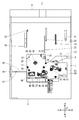
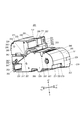
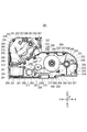
- FIG. 1 It is a perspective view of a tape printer. It is the figure which looked at the tape printer with the tape cartridge mounted from the mounting direction front side. It is the figure which looked at the tape printer with the ribbon cartridge mounted from the mounting direction front side. It is the figure which looked at the tape printer from the mounting direction front side. It is the figure which looked at the ribbon cartridge from the mounting direction front side. It is a perspective view of a ribbon cartridge. It is the figure which looked at the ribbon cartridge from the mounting direction back side. It is the figure which looked at the ribbon part front side case from the mounting direction back side. It is the figure which looked at the tape holding part front side case from the mounting direction back side. FIG.
- FIG. 6 is a diagram of the ribbon cartridge in a state where the slide plate is moved to the closed position, as viewed from the front side in the mounting direction, excluding the ribbon section front side case, the tape holding section front side case, and the slide plate.
- FIG. 9 is a diagram for explaining a printing process performed by the tape printing device with the ribbon cartridge mounted in the cartridge mounting portion. It is a figure which shows the arrangement
- FIG. 6 is a diagram for explaining a printing process performed by the tape printing device with the tape cartridge mounted in the cartridge mounting portion.
- the vertical direction of the tape printer 1 is the Z direction
- the horizontal direction orthogonal to the Z direction is the X direction
- the front-back direction orthogonal to the Z direction and the X direction is the Y direction.
- the downward direction or the gravity direction is the ⁇ Z direction
- the upward direction is the +Z direction.
- the Y direction one direction is the +Y direction and the opposite direction is the ⁇ Y direction.
- the rotation axis side of the mounting portion cover 5 is set to the +Y direction.
- the X direction one direction is +X direction and the opposite direction is -X direction.
- the right side in plan view is the +X direction. Needless to say, these directions are merely for convenience of description and do not limit the following embodiments.
- the tape cartridge 101 contains a first printing tape 103 and a first ink ribbon 105.
- the tape printing apparatus 1 prints on the first printing tape 103 while feeding the first printing tape 103 and the first ink ribbon 105 housed in the tape cartridge 101. I do.
- the ribbon cartridge 201 contains a second ink ribbon 205.
- the second printing tape 403 fed from the tape roll 401 provided outside the tape printing device 1 is introduced into the tape printing device 1.
- the tape printer 1 prints on the second printing tape 403 while feeding the introduced second printing tape 403 and the second ink ribbon 205 accommodated in the ribbon cartridge 201.
- the length of the second printing tape 403 on the tape roll 401 in the unused state and the length of the second ink ribbon 205 accommodated in the ribbon cartridge 201 in the unused state are not particularly limited.
- the length of the first printing tape 103 and the length of the first ink ribbon 105 accommodated in the unused tape cartridge 101 are longer. Therefore, for example, when a large number of labels are created at once, the ribbon cartridge 201 is mounted.
- the tape printer 1 will be described with reference to FIG.
- the tape printer 1 includes a device case 3, a mounting portion cover 5, and a cartridge mounting portion 7.
- the device case 3 is formed in a substantially rectangular parallelepiped shape.
- the device case 3 is provided with a device side tape introduction port 9 for the second printing tape 403 fed from the tape roll 401 on the +X side face, and a device for both the tape cartridge 101 and the ribbon cartridge 201 on the ⁇ X side face.
- a side tape outlet 11 is provided.
- the device-side tape introducing port 9 introduces the second printing tape 403 into the device case 3 from outside the device case 3.
- the device-side tape discharge port 11 discharges the introduced second printing tape 403 to the outside of the device case 3.
- the device-side tape ejection port 11 ejects the first printing tape 103 fed from the tape cartridge 101 mounted in the cartridge mounting portion 7 to the outside of the device case 3.
- the device-side tape introduction port 9 and the device-side tape discharge port 11 are formed in a slit shape extending in the Z direction. Further, in the tape feeding path in the tape printing apparatus 1, the direction in which the second printing tape 403 goes from the apparatus-side tape introduction port 9 to the apparatus-side tape discharge port 11 is downstream and the opposite direction is upstream.
- the device case 3 is provided with a tape introduction path 13 that connects the device-side tape introduction port 9 and the cartridge mounting portion 7. Further, the device case 3 is provided with a tape ejection path 15 that connects the cartridge mounting portion 7 and the device-side tape ejection port 11.
- the tape introduction path 13 and the tape ejection path 15 are formed in a groove shape with the +Z side opened.
- a cutter 17 is provided in the tape discharge path 15. The cutter 17 cuts the first printing tape 103 or the second printing tape 403 in the tape discharge path 15.
- the mounting unit cover 5 opens and closes the cartridge mounting unit 7.
- a first pressing projection 19, a second pressing projection 20, a third pressing projection 21, a fourth pressing projection 22, a fifth pressing projection 23, and a sixth pressing projection. 24 are provided on the inner surface of the mounting portion cover 5.
- a keyboard and a display are provided on the outer surface of the mounting portion cover 5.
- the keyboard receives print information such as a character string and an input operation of various instructions such as print execution.
- the display displays various information in addition to the print information input from the keyboard.
- the display has a rotating shaft serving as a hinge and is configured to be stored in the mounting portion cover 5. When the display is stored in the mounting portion cover 5, the display surface of the display faces the keyboard.
- the tape printer 1 executes print processing based on print information input from the keyboard.
- the tape printer 1 may be configured to include an input display unit such as a touch panel display instead of the keyboard and the display. Further, the tape printer 1 may be configured to execute print processing based on print data and commands received from an external device such as a personal computer or a smartphone. In other words, you may comprise the printing system which combined the tape printer 1 and the external device as an operating terminal.
- the keyboard and the display may or may not be provided in the tape printer 1 when the external device can be connected to these devices.
- Cartridge mounting part 7 is formed in a concave shape with the +Z side open.
- the inner peripheral surface on the ⁇ X side is referred to as a first mounting inner peripheral surface 25.
- the inner peripheral surface extending from the ⁇ Y side end of the first mounting inner peripheral surface 25 to the +X side is referred to as a second mounting inner peripheral surface 27.
- the inner peripheral surface extending from the +X side end of the second mounting inner peripheral surface 27 to the +Y side is referred to as a third mounting inner peripheral surface 29.
- the inner peripheral surface extending from the +Y side end of the third mounting inner peripheral surface 29 to the ⁇ X side is referred to as a fourth mounting inner peripheral surface 31.
- An inner peripheral surface extending from the ⁇ X side end of the fourth mounting inner peripheral surface 31 to the +Y side is referred to as a fifth mounting inner peripheral surface 33.
- the inner peripheral surface extending from the +Y side end of the fifth mounting inner peripheral surface 33 to the ⁇ X side is referred to as a sixth mounting inner peripheral surface 35.
- the ⁇ X side end of the sixth mounting inner peripheral surface 35 is connected to the +Y side end of the first mounting inner peripheral surface 25.
- the downstream end of the tape introduction path 13 is open to the fourth mounting inner peripheral surface 31.
- the upstream end of the tape discharge path 15 is open to the first mounting inner peripheral surface 25.
- the platen shaft 39, the first winding shaft 43, the first feeding shaft 41, and the second feeding shaft are arranged in order from the ⁇ X side. 45 and a second winding shaft 47 are provided so as to project to the +Z side.
- the platen shaft 39 has a larger protrusion amount to the front side in the mounting direction than the first feeding shaft 41, the first winding shaft 43, the second feeding shaft 45, and the second winding shaft 47.
- the platen shaft 39 is inserted into a first platen roller 109 or a second platen roller 203, which will be described later, when the tape cartridge 101 or the ribbon cartridge 201 is mounted in the cartridge mounting portion 7, and the tape cartridge 101 or the ribbon cartridge 201 is mounted.
- the mounting direction of the tape cartridge 101 and the ribbon cartridge 201 is simply referred to as “mounting direction”, and the mounting direction is parallel to the extending direction of the platen shaft 39, that is, the Z direction.
- the front side in the mounting direction means the +Z side
- the back side in the mounting direction means the ⁇ Z side.
- a head portion 49, an engaging convex portion 51, and an inserting convex portion 53 are provided so as to project toward the front side in the mounting direction.
- the head portion 49 is located on the ⁇ Y side of the platen shaft 39.
- the head unit 49 includes a print head 55 and a head cover 56 that covers at least the +X side, the ⁇ Y side, and the front side in the mounting direction of the print head 55.
- the print head 55 is a thermal head including a heating element.
- the head cover 56 is formed in a substantially rectangular shape when viewed from the front side in the mounting direction.
- the head cover 56 guides the mounting of the tape cartridge 101 or the ribbon cartridge 201 together with the platen shaft 39 when the tape cartridge 101 or the ribbon cartridge 201 is mounted in the cartridge mounting portion 7.
- the head cover 56 is virtually shown by a chain double-dashed line in order to illustrate the print head 55.
- the engagement convex portion 51 is located near a corner where the fifth mounting inner peripheral surface 33 and the sixth mounting inner peripheral surface 35 intersect, and is formed in a plate shape facing the fifth mounting inner peripheral surface 33. Has been done. That is, the engagement protrusion 51 is formed in a substantially rectangular shape that is long in the Y direction when viewed from the front side in the mounting direction. Further, the engagement convex portion 51 projects from the mounting bottom surface 37 in the shape of a cantilever.
- the insertion convex portion 53 is located at a substantially intermediate portion between the engaging convex portion 51 and the platen shaft 39, and is formed in a substantially stepped columnar shape having a large diameter on the rear side in the mounting direction and a small diameter on the front side in the mounting direction. ..
- the mounting bottom surface 37 is provided with a first hook 57, a second hook 59, a third hook 61, and a fourth hook 63 protruding toward the front side in the mounting direction.
- the first hook 57 is located on the +Y side of the platen shaft 39 and on the ⁇ X side end of the mounting bottom surface 37.
- the second hook 59 is located on the +Y side of the first feeding shaft 41 and at a position facing the first hook 57 in the X direction.
- the third hook 61 is located at the ⁇ Y side of the substantially middle position between the second feeding shaft 45 and the second winding shaft 47, and at the ⁇ Y side end of the mounting bottom surface 37.
- the fourth hook 63 is located on the +X side of the second winding shaft 47 and on the +X side end of the mounting bottom surface 37.
- a plurality of positioning pins 65 are provided on the mounting bottom surface 37 so as to project toward the front side in the mounting direction.
- a board connecting portion 67 is provided on the fifth mounting inner peripheral surface 33 so as to face the engagement protrusion 51 on the +X side of the engagement protrusion 51.
- the board connecting unit 67 is connected to a control circuit (not shown) that controls each unit of the tape printing apparatus 1.
- the ribbon cartridge 201 will be described with reference to FIGS.
- the ribbon cartridge 201 includes a second platen roller 203, a second feeding core 206, a second winding core 207, a holding tip portion 209, and a second cartridge case 211 accommodating these.
- the ribbon cartridge 201 has the X direction as the longitudinal direction and the Y direction as the lateral direction when viewed from the front side in the mounting direction.
- the second platen roller 203, the second feeding core 206, and the second winding core 207 are the platen shaft 39, the second feeding shaft 45, and the second feeding shaft 45, which are provided in the cartridge mounting portion 7, respectively, when viewed from the front side in the mounting direction. It is provided at a position corresponding to the winding shaft 47.
- the second platen roller 203 is provided with a second platen shaft insertion hole 213 that penetrates in the mounting direction.
- the second ink ribbon 205 is wound around the second feeding core 206.
- the second ink ribbon 205 wound around the second delivery core 206 is referred to as a delivery side roll 208.
- the second ink ribbon 205 fed from the second feeding core 206 is wound around the second winding core 207.
- a roll in which the second ink ribbon 205 is wound around the second winding core 207 is referred to as a winding-side roll 210.
- the delivery side roll 208 in a state where the entire second ink ribbon 205 is wound around the second delivery core 206 is indicated by a broken line, and the entire second ink ribbon 205 is wound around the second delivery core 206.
- the winding side roll 210 in the rolled state is virtually shown by a two-dot chain line.
- the winding-side roll 210 in a state of being wound around the pay-out core 206 is virtually shown by a two-dot chain line.
- the second cartridge case 211 may be of a plurality of types having different thicknesses, that is, dimensions in the mounting direction, depending on the width of the contained second ink ribbon 205.
- the second cartridge case 211 is formed in a shape substantially similar to the cartridge mounting portion 7 when viewed from the front side in the mounting direction.
- the peripheral wall portion on the ⁇ X side is referred to as a ribbon-side first peripheral wall portion 215.
- the peripheral wall portion extending from the ⁇ Y side end of the ribbon side first peripheral wall portion 215 to the +X side is referred to as a ribbon side second peripheral wall portion 217.
- the peripheral wall portion extending from the +X side end of the ribbon side second peripheral wall portion 217 to the +Y side is referred to as a ribbon side third peripheral wall portion 219.
- a peripheral wall portion extending from the +Y-side end of the ribbon-side third peripheral wall portion 219 to the ⁇ X side via the first curved surface 221 is referred to as a ribbon-side fourth peripheral wall portion 223.
- the peripheral wall portion extending from the ⁇ X side end of the ribbon side fourth peripheral wall portion 223 to the +Y side is referred to as a ribbon side fifth peripheral wall portion 225.
- the peripheral wall portion extending from the +Y side end of the ribbon side fifth peripheral wall portion 225 to the ⁇ X side is referred to as a ribbon side sixth peripheral wall portion 227.
- the ⁇ X side end of the ribbon-side sixth peripheral wall 227 is connected to the +Y-side end of the ribbon-side first peripheral wall 215 via the second curved surface 229.
- the ribbon-side fourth peripheral wall portion 223 and the ribbon-side sixth peripheral wall portion 227 have a step formed by the ribbon-side fifth peripheral wall portion 225. Further, when viewed from the front side in the mounting direction, the interior angle ⁇ formed by the ribbon-side fourth peripheral wall portion 223 and the ribbon-side fifth peripheral wall portion 225 exceeds 180° and is, for example, approximately 270°.
- one end portion of the second winding core 207 in the longitudinal direction of the ribbon cartridge 201 that is, the +X side end portion of the second winding core 207 in the peripheral wall portion of the second cartridge case 211.
- the portion that faces is referred to as a first facing portion 228.
- one end of the second winding core 207 in the direction orthogonal to the longitudinal direction of the ribbon cartridge 201 that is, the +Y side end of the second winding core 207.
- the facing portion is referred to as a second facing portion 230.
- the first curved surface 221 is located between the first facing portion 228 and the second facing portion 230 when viewed from the front side in the mounting direction, and is formed in an arc shape protruding toward the outside of the ribbon cartridge 201. ing. As a result, the gap between the take-up roll 210 and the peripheral wall portion of the second cartridge case 211 can be reduced.
- a second head insertion hole 231 is provided in the second cartridge case 211 so as to penetrate in the mounting direction.
- the second head insertion hole 231 is located at a corner where the ribbon-side first peripheral wall portion 215 and the ribbon-side second peripheral wall portion 217 intersect when viewed from the front side in the mounting direction.
- the second head insertion hole 231 is arranged along the ribbon-side first peripheral wall portion 215 and the ribbon-side second peripheral wall portion 217.
- the second head insertion hole 231 is formed in a shape corresponding to the head cover 56, that is, a substantially rectangular shape when viewed from the front side in the mounting direction.
- the second head insertion hole 231 and the second platen shaft insertion hole 213 position the ribbon cartridge 201 and guide the attachment/detachment of the ribbon cartridge 201 when the ribbon cartridge 201 is attached/detached to/from the cartridge mounting portion 7.
- the second cartridge case 211 includes a front side case and a second back side case 237.
- the front side case is divided into a ribbon side front side case 233 and a tape holding portion front side case 235.
- the ribbon front side case 233 is an example of the first case
- the second back side case 237 is an example of the second case.
- the ribbon front side case 233 and the tape holding portion front side case 235 are molded products made of a resin having a light-transmitting property
- the second inner case 237 is a molded product made of a resin having no light-transmitting property.
- the material and manufacturing method of the ribbon unit front side case 233, the tape holding unit front side case 235, and the second back side case 237 are not limited thereto.
- the ribbon front side case 233 includes a ribbon front wall 239 and a ribbon front peripheral wall 241 protruding from the peripheral edge of the ribbon front wall 239 to the rear side in the mounting direction.
- the tape holding portion front side case 235 includes a tape holding portion front wall portion 243 and a tape holding portion front side peripheral wall portion 245 protruding from the peripheral edge portion of the tape holding portion front wall portion 243 toward the mounting direction rear side.
- the second inner case 237 includes a second inner wall portion 247, a ribbon portion inner peripheral wall portion 249 and a tape holding portion inner peripheral wall portion 251 that project from the second inner wall portion 247 to the front side in the mounting direction. There is.
- the ribbon case front side case 233 and the second back side case 237 are combined so that the ribbon section front side peripheral wall portion 241 and the ribbon portion rear side peripheral wall portion 249 are butted against each other, and the ink containing the second ink ribbon 205 is accommodated. It forms the outer shell of the ribbon housing portion 253. That is, the ribbon portion front peripheral wall portion 241 is provided with a plurality of ribbon portion insertion pins 242 (see FIG. 8) projecting to the rear side in the mounting direction, and the ribbon portion rear side peripheral wall portion 249 is disposed on the front side in the mounting direction. A plurality of opened ribbon portion insertion holes 250 (see FIG. 10) are provided.
- the ribbon portion insertion pin 242 By inserting the ribbon portion insertion pin 242 into the ribbon portion insertion hole 250, the ribbon portion front side case 233 and the second rear side case 237 are combined.
- the ribbon portion insertion pin 242 and the ribbon portion insertion hole 250 are provided so as to avoid the first curved surface 221. Therefore, the gap between the winding side roll 210 and the peripheral wall portion of the second cartridge case 211 is made smaller than in the configuration in which the ribbon portion insertion pin 242 and the ribbon portion insertion hole 250 are provided in the first curved surface 221. be able to.
- the tape holding portion front side case 235 and the second back side case 237 are combined so that the tape holding portion front side peripheral wall portion 245 and the tape holding portion back side peripheral wall portion 251 are butted against each other, and the second platen roller 203 and It constitutes the outer shell of the tape holding mechanism housing portion 255 which houses the holding tip portion 209. That is, the tape holding portion front side peripheral wall portion 245 is provided with a plurality of holding portion insertion pins 246 (see FIG. 9) projecting to the back side in the mounting direction, and the tape holding portion rear side peripheral wall portion 251 is mounted in the mounting direction front side. A plurality of holding portion insertion holes 252 (see FIG. 10) opened to the side are provided.
- the tape holding portion front side case 235 and the second back side case 237 are combined.
- the ink ribbon containing portion 253 and the tape holding mechanism containing portion 255 are integrally formed via the second inner wall portion 247.
- the tape holding mechanism housing portion 255 houses the tape holding portion 305 (see FIG. 10) having the holding tip portion 209.
- the tape holding unit 305 is for holding the second printing tape 403 previously introduced into the second tape path 257 described later when the ribbon cartridge 201 is mounted in the cartridge mounting unit 7. That is, the holding tip portion 209 holds the second printing tape 403 introduced into the second tape path 257 between the holding tip portion 209 and the ribbon side path side wall portion 263. As a result, the leading end of the second printing tape 403 introduced into the second tape path 257 is drawn into the second tape path 257, that is, closer to the cartridge-side tape introduction port 259 than the second platen roller 203. Is suppressed.
- the front case 233 of the ribbon portion is provided with a first peripheral wall recess 267, a second peripheral wall recess 269, a third peripheral wall recess 271, and a fourth peripheral wall recess 272.
- the first peripheral wall concave portion 267 is formed in a concave shape on the +X side end of the ribbon side fourth peripheral wall portion 223 from the ribbon front wall portion 239 toward the mounting direction rear side.
- the second peripheral wall concave portion 269 is formed in a groove shape extending in the mounting direction at a substantially middle portion in the X direction of the ribbon-side second peripheral wall portion 217.
- the third peripheral wall concave portion 271 is formed in a concave shape on the ⁇ Y side end of the ribbon-side third peripheral wall portion 219 from the ribbon front wall portion 239 toward the rear side in the mounting direction.
- the fourth peripheral wall recess 272 is formed at the +Y side end of the ribbon-side fifth peripheral wall 225 so as to be recessed from the ribbon front wall 239 toward the rear side in the mounting direction.
- a peripheral wall convex portion 273 is provided at a position corresponding to the second peripheral wall concave portion 269 on the ribbon portion rear side peripheral wall portion 249 so as to project to the front side in the mounting direction.
- the bottom surface of the first peripheral wall concave portion 267, the protruding tip surface of the peripheral wall convex portion 273, and the bottom surface of the third peripheral wall concave portion 271 are referred to as a first pressing portion 275, a second pressing portion 277, and a third pressing portion 279, respectively. ..
- the first pressing portion 275, the second pressing portion 277, and the third pressing portion 279 are provided so as to surround the second feeding core 206 and the second winding core 207 when viewed from the front side in the mounting direction.
- the first pressing portion 275, the second pressing portion 277, and the third pressing portion 279 respectively correspond to the first pressing protrusion 19, the second pressing protrusion 20, and the third pressing protrusion 21 provided on the mounting portion cover 5.
- the bottom surface of the fourth peripheral wall recessed portion 272 and the surface of the cartridge side tape discharge port 261 on the front side in the +Z side mounting direction are referred to as a fourth pressing portion 280 and a fifth pressing portion 282, respectively.
- the fourth retainer portion 280 and the fifth retainer portion 282 are provided at positions corresponding to the fourth retainer protrusion 22 and the fifth retainer protrusion 23 provided on the mounting portion cover 5, respectively.
- the mounting portion cover 5 When the mounting portion cover 5 is closed with the ribbon cartridge 201 mounted in the cartridge mounting portion 7, the first pressing protrusion 19, the second pressing protrusion 20, and the third pressing protrusion 21 provided on the mounting portion cover 5 are released. , And is guided by the first peripheral wall recess 267, the second peripheral wall recess 269 and the third peripheral wall recess 271, respectively, and abuts against the first pressing portion 275, the second pressing portion 277 and the third pressing portion 279. That is, the periphery of the second feeding core 206 and the second winding core 207 is pressed by the first pressing protrusion 19, the second pressing protrusion 20, and the third pressing protrusion 21.
- the second feeding core 206 and the second winding core 207 are prevented from being inclined with respect to the second feeding shaft 45 and the second winding shaft 47 provided in the cartridge mounting portion 7. Therefore, when the second ink ribbon 205 is fed from the second feeding core 206 to the second winding core 207, it is possible to prevent wrinkles from occurring in the second ink ribbon 205.
- the ribbon cartridge 201 can accommodate an ink ribbon having a large ink ribbon width, for example, a width of 50 mm.
- the ribbon cartridge front side case 233 and the tape holding portion front side case 235 are reduced in size in the Z direction. May be At this time, both or either one of the first peripheral wall recessed portion 267 and the third peripheral wall recessed portion 271 is not provided, and both or one of the first pressing protrusion 19 and the third pressing protrusion 21 is provided on the front wall of the ribbon portion. You may make it hold down the part 239.
- the fourth pressing protrusion 22 provided on the mounting portion cover 5 is guided to the fourth peripheral wall recessed portion 272, It hits the fourth pressing portion 280.
- the fourth retainer portion 280 is pressed by the fourth retainer protrusion 22 toward the rear side in the mounting direction, and the second electrode portion 330 of the second circuit board 327 provided near the fourth retainer portion 280 is connected to the contact terminal portion. 83 can be appropriately contacted.
- the fifth pressing protrusion 23 provided on the mounting portion cover 5 abuts against the fifth pressing portion 282.
- the fifth pressing portion 282 is pressed by the fifth pressing protrusion 23 toward the back side in the mounting direction, and the second platen roller 203 provided near the fifth pressing portion 282 is appropriately opposed to the print head 55.
- the ribbon side first peripheral wall portion 215 is provided with a ribbon side first hook engaging portion 321 and the ribbon side second peripheral wall portion 217 is provided with a ribbon side second hook engaging portion.
- the portion 323 is provided, and the ribbon-side third peripheral wall portion 219 is provided with the ribbon-side third hook engaging portion 325.
- a hook insertion hole 299 is formed on the +Y side of the feeding side cylinder portion 283 described later.
- a plurality of second positioning holes 295 are provided on the surface of the second inner wall portion 247 on the inner side in the mounting direction.
- a second circuit board 327 is attached to the ribbon-side fifth peripheral wall portion 225 of the ribbon-portion rear peripheral wall portion 249. That is, the second circuit board 327 is attached to the ribbon-side fifth peripheral wall portion 225 provided substantially in parallel with the ribbon-side first peripheral wall portion 215 provided with the cartridge-side tape discharge port 261.
- the ribbon-side fifth peripheral wall portion 225 is provided with a second board attachment portion 337 to which the second circuit board 327 is attached.
- the ribbon-side fifth peripheral wall portion 225 is bent such that the internal angle ⁇ exceeds 180° with respect to the ribbon-side fourth peripheral wall portion 223 when viewed from the front side in the mounting direction. Therefore, when the ribbon cartridge 201 is dropped on the floor or the like, the first curved surface 221 between the ribbon-side third peripheral wall portion 219 and the ribbon-side fourth peripheral wall portion 223 or the ribbon-side fifth peripheral wall portion 225 The corner portion where the ribbon-side sixth peripheral wall portion 227 intersects will hit the floor or the like, and the ribbon-side fourth peripheral wall portion 223 and the ribbon-side fifth peripheral wall portion 225 will be suppressed from hitting the floor or the like.
- the second electrode portion 330 provided on the second circuit board 327 is suppressed from hitting the floor or the like, and the second electrode portion 330 having low mechanical strength is damaged. Can be suppressed.
- the same operational effect can be obtained.
- the second tape path 257 will be described based on FIGS. 5, 6 and 10.
- the second tape path 257 is located between the ribbon unit front side case 233 and the tape holding unit front side case 235, and is formed in a groove shape whose front side in the mounting direction is open. That is, the set opening 258 is provided on the front side of the second tape path 257 in the mounting direction.
- the set opening 258 is for the user to set the second printing tape 403 in the second tape path 257 from the end surface on the back side in the mounting direction of the second printing tape 403.
- a part of the set opening portion 258 is opened and closed by sliding the slide plate 313 in the Y direction with respect to the front wall portion 243 of the tape holding portion.
- the second tape path 257 connects the cartridge-side tape introduction port 259 provided on the ribbon-side fifth peripheral wall portion 225 and the cartridge-side tape discharge port 261 provided on the ribbon-side first peripheral wall portion 215.
- the cartridge-side tape introducing port 259 is provided between the ink ribbon containing section 253 and the second circuit board 327. That is, the cartridge-side tape introduction port 259 is located closer to the ribbon-side fourth peripheral wall portion 223 than the second circuit board 327 is.
- the cartridge-side tape introduction port 259 is provided in a region of the ribbon-side fifth peripheral wall portion 225 that intersects with the ribbon-side fourth peripheral wall portion 223 at a distance from the second circuit board 327.
- the cartridge-side tape introduction port 259 may be provided in the ribbon-side fourth peripheral wall portion 223. In that case, in order to make a simple arrangement structure, it is desirable to bring it closer to the region where the ribbon-side fifth peripheral wall portion 225 and the ribbon-side fourth peripheral wall portion 223 intersect.
- the cartridge-side tape introduction port 259 introduces the second printing tape 403 introduced from the device-side tape introduction port 9 into the second cartridge case 211 in a state where the ribbon cartridge 201 is attached to the cartridge attachment portion 7.
- the cartridge-side tape ejection port 261 ejects the second printing tape 403 toward the apparatus-side tape ejection port 11 to the outside of the second cartridge case 211 when the ribbon cartridge 201 is mounted in the cartridge mounting portion 7.
- the cartridge-side tape introduction port 259 and the cartridge-side tape discharge port 261 are formed in a slit shape along the mounting direction. For this reason, the second printing tape 403 introduced into the second cartridge case 211 is fed such that the width direction of the second printing tape 403 is substantially parallel to the mounting direction.
- the side wall on the ink ribbon containing section 253 side is called the ribbon side path side wall section 263, and the side wall on the tape holding mechanism containing section 255 side is the tape holding mechanism side path side wall section. 265.
- the ribbon-side path side wall portion 263 and the tape holding mechanism-side path side wall portion 265 face each other.
- the second tape path 257 is provided with a second platen roller 203 and a holding tip portion 209 in order from the side closer to the cartridge side tape discharge port 261.
- a portion of the tape holding mechanism side path side wall portion 265 corresponding to the holding tip end portion 209 is located between the ribbon side path side wall portion 263 and the second printing tape 403 having the holding tip end portion 209 introduced into the second tape path 257. Notched so it can be held in.
- the end of the second tape path 257 on the side of the cartridge-side tape ejection port 261 is connected to the second head insertion hole 231 via the second ribbon exposed portion 291 described later.
- the second inner case 237 will be described with reference to FIG.
- the guide 289 is provided so as to project to the front side in the mounting direction.
- the second head peripheral projection 281 is provided on the peripheral portion of the second head insertion hole 231.
- the second head peripheral edge convex portion 281 is notched on the +Y side, that is, on the second platen roller 203 side, and the notched portion exposes the second ink ribbon 205 to the second ribbon exposed portion 291. Has become.
- the feeding-side cylinder portion 283 and the winding-side cylinder portion 285 are provided at positions corresponding to the first feeding shaft 41 and the first winding shaft 43 provided in the cartridge mounting portion 7, respectively, when viewed from the front side in the mounting direction. Has been.
- the first feeding shafts provided in the cartridge mounting portion 7 are respectively provided in the feeding side tubular portion 283 and the winding side tubular portion 285 provided in the ribbon cartridge 201. 41 and the first winding shaft 43 are inserted. Thereby, when the ribbon cartridge 201 is mounted in the cartridge mounting portion 7, the first feeding shaft 41 and the first winding shaft 43 are prevented from interfering with the ribbon cartridge 201.
- the second ink ribbon 205 delivered from the second delivery core 206 has a delivery side tubular portion 283, a second head peripheral edge convex portion 281, a winding side tubular portion 285, a first ribbon guide 287, and a second ribbon guide 289 in this order. While being guided, it is wound around the second winding core 207. That is, the feeding-side cylinder portion 283 and the winding-side cylinder portion 285 not only insert the first feeding shaft 41 and the first winding shaft 43, but also function as guide members for guiding the second ink ribbon 205. ..
- a second tubular shaft portion 293 is provided on the second inner wall portion 247 so as to project toward the front side in the mounting direction.
- the second tubular shaft portion 293 is formed in a substantially stepped cylindrical shape.
- a second convex receiving portion 297 is provided on the second inner wall portion 247 at a corner where the ribbon-side fifth peripheral wall portion 225 and the ribbon-side sixth peripheral wall portion 227 intersect.
- the second convex portion receiving portion 297 provided in the ribbon cartridge 201 receives the engaging convex portion 51 provided in the cartridge mounting portion 7.
- the head portion 49 provided in the cartridge mounting portion 7 is inserted into the second head insertion hole 231 provided in the ribbon cartridge 201.
- the mounting portion cover 5 is closed after the ribbon cartridge 201 is mounted in the cartridge mounting portion 7, the print head 55 moves toward the platen shaft 39 by a head moving mechanism (not shown).
- the second print tape 403 and the second ink ribbon 205 are held between the print head 55 and the second platen roller 203.
- the second platen roller 203 rotates in the return direction and the second feeding core 206 rotates in the rewind direction. Accordingly, the second printing tape 403 ejected from the cartridge-side tape ejection port 261 is pulled back into the second cartridge case, and the second ink ribbon 205 fed from the second feeding core 206 is also fed. Are rewound on the second feeding core 206. In this way, the second payout shaft 45 that is inserted into the second payout core 206 and the second takeup shaft 47 that is inserted into the second takeup core 207 are the second ink ribbon transport mechanism that sends the second ink ribbon 205. Is composed of.
- the tape printer 1 rotates the feed motor in the forward direction and heats the print head 55 to feed the second print tape 403 and the second ink ribbon 205, and at the same time, to print the print information input from the keyboard or the like. 2 Print on the printing tape 403. After the printing is completed, the tape printer 1 causes the cutter 17 to perform a cutting operation to separate the printed portion of the second printing tape 403. After that, the tape printing apparatus 1 rotates the feed motor in the returning direction to perform the second printing until the leading end of the second printing tape 403 comes close to the nipping position between the printing head 55 and the second platen roller 203. The tape 403 is pulled back. As a result, it is possible to shorten the blank space generated in the front in the length direction of the second printing tape 403 to be printed next.
- the second platen roller 203 is provided near one end in the longitudinal direction of the ribbon cartridge 201, that is, near the end on the ⁇ X side when viewed from the front side in the mounting direction.
- the second feeding core 206 and the second winding core 207 are provided near the other end in the longitudinal direction of the ribbon cartridge 201, that is, near the +X side end when viewed from the front side in the mounting direction.
- the second feeding core 206 is provided between the second platen roller 203 and the second winding core 207.
- the second feeding core 206 is arranged closer to the second platen roller 203 than the second winding core 207.
- the dimension between the second feeding core 206 and the second platen roller 203 is shortened, so that the second ink ribbon 205 may be wrinkled between the second feeding core 206 and the second platen roller 203. Can be suppressed.
- the virtual straight line L extends in the longitudinal direction of the ribbon cartridge 201 when viewed from the rotation axis direction parallel to the rotation axis of the second feeding core 206 and the rotation axis of the second winding core 207, and extends on the second platen roller 203. It is a virtual straight line that passes through the center.
- the rotation axis of the second pay-out core 206 and the rotation axis of the second winding core 207 are parallel to the mounting direction, so the rotation axis direction parallel to these rotation axes is the mounting direction.
- the inter-core dimension D is a dimension between the center of the second feeding core 206 and the center of the second winding core 207.
- the maximum feeding-side roll radius r1 is the radius of the feeding-side roll 208 when the entire second ink ribbon 205 is wound around the second feeding core 206.
- the maximum winding-side roll radius r2 is the radius of the winding-side roll 210 when the entire second ink ribbon 205 is wound around the second winding core 207.
- the roll total value is a total value of the maximum feeding-side roll radius r1 and the maximum winding-side roll radius r2.
- the second feeding core 206 and the second winding core 207 are arranged so that at least a part thereof overlaps the virtual straight line L when viewed from the front side in the mounting direction. Therefore, as the winding of the second ink ribbon 205 progresses, the center of gravity of the ribbon cartridge 201 moves in a direction substantially parallel to the virtual straight line L. That is, the second platen roller 203, which is a heavy object, is provided on a substantially extended line in the moving direction of the center of gravity. For this reason, the second platen roller 203 functions as a balancer, and the amount of movement of the center of gravity of the ribbon cartridge 201 as the winding of the second ink ribbon 205 progresses is reduced.
- the second feeding core 206 and the second winding core 207 are prevented from being inclined with respect to the second feeding shaft 45 and the second winding shaft 47 provided in the cartridge mounting portion 7. Further, when the user attaches and detaches the ribbon cartridge 201, the ribbon cartridge 201 is less likely to be tilted with respect to the attaching direction, so that the ribbon cartridge 201 can be attached and detached smoothly.
- the dimension D between cores is smaller than the total roll value. That is, the second feeding core 206 and the second winding core 207 are arranged close to each other. As a result, the amount of movement of the center of gravity of the ribbon cartridge 201 as the winding of the second ink ribbon 205 progresses can be reduced. Further, the ribbon cartridge 201 can be downsized.
- the tape cartridge 101 will be described with reference to FIGS. 13 to 15.
- the tape cartridge 101 includes a tape core 107, a first platen roller 109, a first feeding core 111, a first winding core 113, and a first cartridge case 115 that rotatably accommodates these.
- the tape core 107, the first platen roller 109, the first feeding core 111, and the first winding core 113 when viewed from the front side in the mounting direction, respectively, the insertion convex portion 53, the platen shaft 39, provided on the cartridge mounting portion 7, It is provided at a position corresponding to the first feeding shaft 41 and the first winding shaft 43.
- the first platen roller 109 is provided with a first platen shaft insertion hole 117 that penetrates in the mounting direction.
- the first printing tape 103 is wound around the tape core 107.
- the first printing tape 103 delivered from the tape core 107 is delivered to the outside of the first cartridge case 115 from a tape delivery outlet 119 provided in the tape-side first peripheral wall portion 123 described later.
- a first tape path 121 from the tape core 107 to the tape outlet 119 is provided in the first cartridge case 115.
- the first ink ribbon 105 is wound around the first feeding core 111.
- the first ink ribbon 105 fed from the first feeding core 111 is wound around the first winding core 113.
- the first cartridge case 115 may be of a plurality of types having different thicknesses, that is, dimensions in the mounting direction, depending on the widths of the first printing tape 103 and the first ink ribbon 105 housed therein.
- the first cartridge case 115 is formed by bending both ends of the long side of the rectangle in the same direction and at a right angle when viewed from the front side in the mounting direction.
- the peripheral wall portion on the ⁇ X side is referred to as a tape-side first peripheral wall portion 123.
- the peripheral wall portion extending from the ⁇ Y side end of the tape side first peripheral wall portion 123 to the +X side is referred to as a tape side second peripheral wall portion 125.
- a peripheral wall portion extending from the +X side end of the tape side second peripheral wall portion 125 to the +Y side is, in order from the ⁇ Y side, a tape side third peripheral wall portion 127, a tape side fourth peripheral wall portion 129, and a tape side fifth peripheral wall portion. It's called 131.
- the tape-side fourth peripheral wall portion 129 is formed in a concave shape with respect to the tape-side third peripheral wall portion 127 and the tape-side fifth peripheral wall portion 131.
- the peripheral wall portion extending from the +Y side end of the tape-side fifth peripheral wall portion 131 to the ⁇ X side is referred to as a tape-side sixth peripheral wall portion 133.
- the ⁇ X side end of the tape side sixth peripheral wall portion 133 is connected to the +Y side end of the tape side first peripheral wall portion 123.
- a first head insertion hole 135 is provided in the first cartridge case 115 so as to penetrate in the mounting direction.
- the first head insertion hole 135 is located at a corner where the tape-side first peripheral wall portion 123 and the tape-side second peripheral wall portion 125 intersect with each other when viewed from the front side in the mounting direction.
- the first head insertion hole 135 is formed in a shape corresponding to the head cover 56, that is, a substantially rectangular shape when viewed from the front side in the mounting direction.
- the first head insertion hole 135 and the first platen shaft insertion hole 117 position the tape cartridge 101 and guide the attachment and detachment of the tape cartridge 101 when the tape cartridge 101 is attached to and detached from the cartridge mounting portion 7.
- the first cartridge case 115 includes a first front side case 137 and a first back side case 139.
- the first front side case 137 is the front side in the mounting direction and the first back side case 139 is the rear side in the mounting direction.
- the first front case 137 is a resin molded product having a light-transmitting property
- the first back case 139 is a resin molded product having no light-transmitting property.
- the material and manufacturing method of the 1 back side case 139 are not limited to this.
- the first front-side case 137 includes a first front-side wall portion 141 and a first front-side peripheral wall portion 143 that protrudes from the peripheral portion of the first front-side wall portion 141 toward the rear side in the mounting direction.
- the first back side case 139 includes a first back side wall portion 145 and a first back side peripheral wall portion 147 protruding from the peripheral edge portion of the first back side wall portion 145 to the front side in the mounting direction.
- the first front side case 137 and the first back side case 139 are combined so that the first front side peripheral wall portion 143 and the first back side peripheral wall portion 147 are butted against each other.
- An elastic portion 149 is provided on the first front wall portion 141 at a corner where the tape-side second peripheral wall portion 125 and the tape-side third peripheral wall portion 127 intersect.
- the elastic portion 149 is formed as a substantially rectangular portion obtained by removing the first front wall portion 141 in a “U” shape when viewed from the front side in the mounting direction.
- the pressing force that accompanies the elastic displacement of the elastic portion 149 is received by the second pressing protrusion 20, and as a result, the tape cartridge 101 is pressed to the rear side in the mounting direction. As a result, the tape cartridge 101 is prevented from being mounted in a state of being lifted from the mounting bottom surface 37.
- the first back wall portion 145 is provided with the first head peripheral edge convex portion 151 protruding from the peripheral edge portion of the first head insertion hole 135 toward the front side in the mounting direction.
- a first ribbon exposing portion 153 for exposing the first ink ribbon 105 is provided on the +Y side of the first head peripheral edge convex portion 151, that is, on the first platen roller 109 side.
- the first ink ribbon 105 is not shown.
- a first tubular shaft portion 155 is provided on the first back wall portion 145 so as to project toward the front side in the mounting direction.
- the first tubular shaft portion 155 is formed in a substantially stepped cylindrical shape, and rotatably supports the tape core 107.
- first positioning holes 157 are provided diagonally on the surface of the first back wall portion 145 on the back side in the mounting direction.
- first back wall portion 145 is provided with a first convex portion receiving portion 159 at a corner where the tape-side fifth peripheral wall portion 131 and the tape-side sixth peripheral wall portion 133 intersect.
- first convex portion receiving portion 159 provided in the tape cartridge 101 receives the engaging convex portion 51 provided in the cartridge mounting portion 7.
- the tape side first peripheral wall portion 123 is provided with the tape side first hook engaging portion 161
- the tape side fourth peripheral wall portion 129 is provided with the tape side second hook engaging portion 129.
- a section 163 is provided.
- the first circuit board 165 is attached to the tape-side fifth peripheral wall portion 131 provided substantially parallel to the tape-side first peripheral wall portion 123 provided with the tape delivery port 119.
- the tape-side fifth peripheral wall portion 131 is provided with a first board attachment portion 167 to which the first circuit board 165 is attached.
- the first grip 173 projects from the tape-side first peripheral wall 123 toward the ⁇ X side
- the second grip 175 projects from the tape-side fourth peripheral wall 129.
- the first grip portion 173 and the second grip portion 175 are provided at a substantially middle portion in the Y direction in the entire first cartridge case 115 when viewed from the front side in the mounting direction.
- the first grip 173 and the second grip 175 serve as clues when the user grips the tape cartridge 101.
- the surface of the first grip portion 173 on the front side in the mounting direction is referred to as a sixth pressing portion 177.
- the head portion 49 provided in the cartridge mounting portion 7 is inserted into the first head insertion hole 135 provided in the tape cartridge 101.
- the mounting portion cover 5 is closed after the tape cartridge 101 is mounted in the cartridge mounting portion 7, the print head 55 is moved toward the platen shaft 39 by a head moving mechanism (not shown). As a result, the first printing tape 103 and the first ink ribbon 105 are held between the print head 55 and the first platen roller 109.
- the first platen roller 109 rotates in the forward direction and the first winding core 113 rotates in the winding direction.
- the first printing tape 103 delivered from the tape core 107 is delivered to the apparatus-side tape ejection port 11 through the tape delivery port 119, and the first ink ribbon 105 delivered from the first delivery core 111. Is wound around the first winding core 113.
- the first platen roller 109 rotates in the reverse direction opposite to the forward direction, and the first feeding core 111 rotates in the rewinding direction.
- the first printing tape 103 ejected from the tape delivery port 119 is pulled back into the first cartridge case, and the first ink ribbon 105 fed from the first feeding core 111 is wound around the first feeding core 111. Will be returned.
- the first payout shaft 41 that is inserted into the first payout core 111 and the first takeup shaft 43 that is inserted into the first takeup core 113 are the first ink ribbon transport mechanism that sends the first ink ribbon 105. Is composed of.
- the tape printer 1 rotates the feed motor in the forward direction and heats the print head 55 to feed the first printing tape 103 and the first ink ribbon 105, and at the same time, print information input from a keyboard or the like. 1 Print on the printing tape 103. After the printing is completed, the tape printer 1 causes the cutter 17 to perform a cutting operation to separate the printed portion of the first printing tape 103. After that, in the tape printer 1, the feed motor is rotated in the return direction so that the front end of the first printing tape 103 is near the nipping position between the print head 55 and the first platen roller 109, that is, near the printing position. The first printing tape 103 is pulled back until it comes to. As a result, it is possible to shorten the margin that occurs in the front in the length direction of the first printing tape 103 to be printed next due to the fact that the print head 55 and the cutter 17 are separated from each other.
- the tape cartridge 101 may not have the first circuit board 165.
- the ribbon cartridge 201 may be configured without the second circuit board 327.
- the ribbon cartridge 201 may not have the tape holding portion 305.
- the cartridge is not limited to the configuration that accommodates the printing tape or the ink ribbon like the tape cartridge 101 and the ribbon cartridge 201 of the present embodiment, and may be any configuration that can be attached to the tape printing apparatus 1.
- the cartridge mounting portion 7 is not limited to the configuration in which the tape cartridge 101 and the ribbon cartridge 201 are selectively mounted, but may be configured to mount only the ribbon cartridge 201. Further, the above-described embodiments and modified examples may be combined together.
- a cartridge mounted on a tape printer comprising a platen roller, a feeding core around which an ink ribbon is wound, and a winding core around which an ink ribbon fed from the feeding core is wound up.
- the feeding core and the winding core pass through the center of the platen roller and extend at least partially in a virtual straight line extending in the longitudinal direction of the cartridge. It is arranged to overlap.
- the center of gravity of the cartridge moves in a direction substantially parallel to the virtual straight line as the winding of the ink ribbon progresses. That is, the platen roller, which is a heavy object, is provided on a substantially extended line in the moving direction of the center of gravity. For this reason, it is possible to reduce the amount of movement of the center of gravity of the cartridge as the winding of the ink ribbon progresses. This prevents the cartridge from tilting with respect to the tape printer. Therefore, it is possible to prevent wrinkles from entering the ink ribbon, and to prevent printing defects such as print wrinkles from occurring.
- the ribbon cartridge 201 when the user attaches and detaches the ribbon cartridge 201, if the user grips the ribbon-side second peripheral wall portion 217 and the ribbon-side fourth peripheral wall portion 223, it is easy to hold. Since the center of gravity of the cartridge moves in a direction substantially parallel to the second ribbon-side peripheral wall portion 217 and the fourth ribbon-side peripheral wall portion 223, when the user attaches or detaches the ribbon cartridge 201, the ribbon cartridge 201 moves in the mounting direction. It becomes difficult to tilt and can be attached and removed smoothly.
- the platen roller is provided near one end portion in the longitudinal direction of the cartridge when viewed from the rotation axis direction, and the feeding core and the take-up core are arranged on the other side in the longitudinal direction of the cartridge when viewed from the rotation axis direction. It is preferably provided near the end.
- the feeding core is provided closer to the platen roller than the winding core.
- the inter-core dimension which is the dimension between the center of the pay-out core and the center of the take-up core, is the maximum pay-out side roll that is the radius of the pay-out side roll when the entire ink ribbon is wound around the pay-out core. It is preferable that it is smaller than the roll total value that is the total value of the radius and the maximum winding-side roll radius that is the radius of the winding-side roll when the entire ink ribbon is wound around the winding core.
- the feeding core and the winding core are arranged close to each other. This makes it possible to reduce the amount of movement of the center of gravity of the cartridge as the winding of the ink ribbon progresses. Further, the cartridge can be downsized.
- the cartridge case includes a platen roller, a feeding core, and a winding core.
- the cartridge case has a peripheral wall portion, and the peripheral wall portion has a winding direction in the longitudinal direction of the cartridge when viewed from the rotation axis direction.
- the cartridge case is located between a first facing portion facing one end of the core and a second facing portion facing one end of the winding core in a direction orthogonal to the longitudinal direction of the cartridge. It is preferable to provide a curved surface that is convex toward the outside of the.
- the gap between the roll on the winding side and the peripheral wall can be reduced. Therefore, the cartridge can be downsized.
- the cartridge case has a first case and a second case that are combined with each other in the rotation axis direction, and the peripheral wall portion is provided in the first peripheral wall portion provided in the first case and the second case. And a second peripheral wall portion, wherein one of the first peripheral wall portion and the second peripheral wall portion is provided with an insertion hole, and the other of the first peripheral wall portion and the second peripheral wall portion is inserted into the insertion hole.
- a pin is preferably provided, and the insertion hole and the insertion pin are preferably provided so as to avoid the curved surface.
- the gap between the winding-side roll and the peripheral wall portion can be made smaller than the configuration in which the insertion hole and the insertion pin are provided on the curved surface.
- the tape printing apparatus includes a cartridge mounting portion in which the cartridge is mounted, a print head that is provided in the cartridge mounting portion, holds the ink ribbon and the printing tape between the platen roller, and prints on the printing tape.
- An apparatus case is provided, and an apparatus-side tape introduction port for introducing the printing tape from the outside of the apparatus case into the apparatus case and an apparatus-side tape ejection port for ejecting the printing tape out of the apparatus case are provided in the apparatus case.
- the cartridge is preferably provided with a tape path through which the printing tape introduced from the device-side tape introduction port is fed toward the device-side tape discharge port when the cartridge is mounted in the cartridge mounting portion.
Landscapes
- Impression-Transfer Materials And Handling Thereof (AREA)
- Printers Characterized By Their Purpose (AREA)
Abstract
Le problème à résoudre par la présente invention est de fournir une cartouche qui peut réduire la quantité de déplacement du centre de gravité de la cartouche associée à l'avancement de la prise d'un ruban d'encre. La solution selon l'invention porte sur une cartouche destinée à être montée dans un dispositif d'impression par bande, comprenant un rouleau de plateau, un noyau de sortie sur lequel est enroulé un ruban d'encre et un noyau de prise sur lequel est pris le ruban d'encre sortant du noyau de sortie. Le noyau de sortie et le noyau de prise sont disposés de sorte que, vu depuis la direction d'un axe de rotation parallèle à l'axe de rotation du noyau de sortie et de celui du noyau de prise, au moins des parties des noyaux chevauchent une ligne virtuelle qui passe à travers le centre du rouleau de plateau et s'étend dans la direction longitudinale de la cartouche.
Priority Applications (6)
| Application Number | Priority Date | Filing Date | Title |
|---|---|---|---|
| US17/418,904 US11872808B2 (en) | 2018-12-26 | 2019-12-23 | Cartridge |
| KR1020217020709A KR102781013B1 (ko) | 2018-12-26 | 2019-12-23 | 카트리지 |
| FIEP19906326.4T FI3904111T3 (fi) | 2018-12-26 | 2019-12-23 | Kasetti |
| DK19906326.4T DK3904111T3 (da) | 2018-12-26 | 2019-12-23 | Patron |
| EP19906326.4A EP3904111B8 (fr) | 2018-12-26 | 2019-12-23 | Cartouche |
| CN201980081253.7A CN113165401B (zh) | 2018-12-26 | 2019-12-23 | 墨盒 |
Applications Claiming Priority (2)
| Application Number | Priority Date | Filing Date | Title |
|---|---|---|---|
| JP2018-243223 | 2018-12-26 | ||
| JP2018243223A JP7213680B2 (ja) | 2018-12-26 | 2018-12-26 | カートリッジ |
Publications (1)
| Publication Number | Publication Date |
|---|---|
| WO2020137962A1 true WO2020137962A1 (fr) | 2020-07-02 |
Family
ID=71127276
Family Applications (1)
| Application Number | Title | Priority Date | Filing Date |
|---|---|---|---|
| PCT/JP2019/050327 Ceased WO2020137962A1 (fr) | 2018-12-26 | 2019-12-23 | Cartouche |
Country Status (9)
| Country | Link |
|---|---|
| US (1) | US11872808B2 (fr) |
| EP (1) | EP3904111B8 (fr) |
| JP (1) | JP7213680B2 (fr) |
| KR (1) | KR102781013B1 (fr) |
| CN (1) | CN113165401B (fr) |
| DK (1) | DK3904111T3 (fr) |
| FI (1) | FI3904111T3 (fr) |
| TW (1) | TWI726547B (fr) |
| WO (1) | WO2020137962A1 (fr) |
Cited By (1)
| Publication number | Priority date | Publication date | Assignee | Title |
|---|---|---|---|---|
| CN115700026A (zh) * | 2020-07-09 | 2023-02-03 | 株式会社富士 | 带式供料器 |
Citations (7)
| Publication number | Priority date | Publication date | Assignee | Title |
|---|---|---|---|---|
| US4480936A (en) * | 1983-01-24 | 1984-11-06 | K-Sun Corporation | Two-piece tape/ribbon cartridge |
| JPS63156753U (fr) * | 1987-03-31 | 1988-10-14 | ||
| JP2000006488A (ja) * | 1998-06-23 | 2000-01-11 | Victor Co Of Japan Ltd | 熱転写プリンタ用カセット |
| JP2012020543A (ja) * | 2010-07-16 | 2012-02-02 | Seiko Epson Corp | テープカートリッジおよびテープ印刷装置 |
| JP2012525282A (ja) * | 2009-04-28 | 2012-10-22 | ダイモ | ラベルプリンタに使用されるカセット |
| JP2013144441A (ja) | 2013-02-26 | 2013-07-25 | Brother Industries Ltd | テープカセット |
| WO2019189710A1 (fr) * | 2018-03-29 | 2019-10-03 | セイコーエプソン株式会社 | Cartouche de ruban et dispositif d'impression |
Family Cites Families (8)
| Publication number | Priority date | Publication date | Assignee | Title |
|---|---|---|---|---|
| JPH03215066A (ja) * | 1990-01-19 | 1991-09-20 | Fuji Xerox Co Ltd | 熱転写記録装置 |
| US5537135A (en) * | 1993-01-22 | 1996-07-16 | Gerber Scientific Products, Inc. | Method and apparatus for making a graphic product |
| JP2004098426A (ja) | 2002-09-09 | 2004-04-02 | Alps Electric Co Ltd | インクリボンカセット |
| EP2514600B1 (fr) | 2009-12-16 | 2015-01-21 | Brother Kogyo Kabushiki Kaisha | Cassette à bande |
| CN203844430U (zh) * | 2014-01-29 | 2014-09-24 | 精工爱普生株式会社 | 带盒 |
| JP6113207B2 (ja) * | 2014-03-24 | 2017-04-12 | セイコーエプソン株式会社 | テープカートリッジ |
| JP6397719B2 (ja) * | 2014-10-16 | 2018-09-26 | セイコーエプソン株式会社 | テープカートリッジ |
| JP6641811B2 (ja) * | 2015-09-08 | 2020-02-05 | マックス株式会社 | インクリボン、インクリボンカセット及びプリンタ |
-
2018
- 2018-12-26 JP JP2018243223A patent/JP7213680B2/ja active Active
-
2019
- 2019-12-23 KR KR1020217020709A patent/KR102781013B1/ko active Active
- 2019-12-23 DK DK19906326.4T patent/DK3904111T3/da active
- 2019-12-23 TW TW108147148A patent/TWI726547B/zh active
- 2019-12-23 US US17/418,904 patent/US11872808B2/en active Active
- 2019-12-23 WO PCT/JP2019/050327 patent/WO2020137962A1/fr not_active Ceased
- 2019-12-23 CN CN201980081253.7A patent/CN113165401B/zh active Active
- 2019-12-23 EP EP19906326.4A patent/EP3904111B8/fr active Active
- 2019-12-23 FI FIEP19906326.4T patent/FI3904111T3/fi active
Patent Citations (7)
| Publication number | Priority date | Publication date | Assignee | Title |
|---|---|---|---|---|
| US4480936A (en) * | 1983-01-24 | 1984-11-06 | K-Sun Corporation | Two-piece tape/ribbon cartridge |
| JPS63156753U (fr) * | 1987-03-31 | 1988-10-14 | ||
| JP2000006488A (ja) * | 1998-06-23 | 2000-01-11 | Victor Co Of Japan Ltd | 熱転写プリンタ用カセット |
| JP2012525282A (ja) * | 2009-04-28 | 2012-10-22 | ダイモ | ラベルプリンタに使用されるカセット |
| JP2012020543A (ja) * | 2010-07-16 | 2012-02-02 | Seiko Epson Corp | テープカートリッジおよびテープ印刷装置 |
| JP2013144441A (ja) | 2013-02-26 | 2013-07-25 | Brother Industries Ltd | テープカセット |
| WO2019189710A1 (fr) * | 2018-03-29 | 2019-10-03 | セイコーエプソン株式会社 | Cartouche de ruban et dispositif d'impression |
Non-Patent Citations (1)
| Title |
|---|
| See also references of EP3904111A4 |
Cited By (1)
| Publication number | Priority date | Publication date | Assignee | Title |
|---|---|---|---|---|
| CN115700026A (zh) * | 2020-07-09 | 2023-02-03 | 株式会社富士 | 带式供料器 |
Also Published As
| Publication number | Publication date |
|---|---|
| JP7213680B2 (ja) | 2023-01-27 |
| US11872808B2 (en) | 2024-01-16 |
| EP3904111A1 (fr) | 2021-11-03 |
| CN113165401A (zh) | 2021-07-23 |
| FI3904111T3 (fi) | 2024-04-23 |
| EP3904111A4 (fr) | 2022-09-14 |
| DK3904111T3 (da) | 2024-03-25 |
| KR20210107028A (ko) | 2021-08-31 |
| JP2020104330A (ja) | 2020-07-09 |
| EP3904111B1 (fr) | 2024-02-21 |
| US20220009252A1 (en) | 2022-01-13 |
| KR102781013B1 (ko) | 2025-03-12 |
| CN113165401B (zh) | 2023-06-30 |
| TWI726547B (zh) | 2021-05-01 |
| EP3904111B8 (fr) | 2024-03-27 |
| TW202023843A (zh) | 2020-07-01 |
Similar Documents
| Publication | Publication Date | Title |
|---|---|---|
| JP7361858B2 (ja) | リボンカートリッジ | |
| JP7073846B2 (ja) | 印刷カートリッジ、テープガイドおよび印刷装置 | |
| KR102474516B1 (ko) | 리본 카트리지 및 인쇄 장치 | |
| CN111376617B (zh) | 盒 | |
| JP7467701B2 (ja) | カートリッジ | |
| JP7467697B2 (ja) | カートリッジ | |
| JP7213678B2 (ja) | テープ印刷装置、カートリッジのセット | |
| JP2020104510A (ja) | カートリッジ | |
| CN111376620B (zh) | 装配于带印刷装置的盒 | |
| CN111376618B (zh) | 装配于带印刷装置的盒 | |
| WO2020137962A1 (fr) | Cartouche | |
| CN111902293B (zh) | 色带盒 | |
| CN113165402B (zh) | 墨盒 | |
| JP7848486B2 (ja) | 印刷装置 | |
| CN104044374B (zh) | 带盒 | |
| JP2023080686A (ja) | テープカセット |
Legal Events
| Date | Code | Title | Description |
|---|---|---|---|
| 121 | Ep: the epo has been informed by wipo that ep was designated in this application |
Ref document number: 19906326 Country of ref document: EP Kind code of ref document: A1 |
|
| NENP | Non-entry into the national phase |
Ref country code: DE |
|
| ENP | Entry into the national phase |
Ref document number: 2019906326 Country of ref document: EP Effective date: 20210726 |