WO2020138077A1 - Système de transfert de chaleur et machines de transfert - Google Patents
Système de transfert de chaleur et machines de transfert Download PDFInfo
- Publication number
- WO2020138077A1 WO2020138077A1 PCT/JP2019/050595 JP2019050595W WO2020138077A1 WO 2020138077 A1 WO2020138077 A1 WO 2020138077A1 JP 2019050595 W JP2019050595 W JP 2019050595W WO 2020138077 A1 WO2020138077 A1 WO 2020138077A1
- Authority
- WO
- WIPO (PCT)
- Prior art keywords
- pump
- working fluid
- heat
- temperature
- evaporator
- Prior art date
- Legal status (The legal status is an assumption and is not a legal conclusion. Google has not performed a legal analysis and makes no representation as to the accuracy of the status listed.)
- Ceased
Links
Images




Classifications
-
- F—MECHANICAL ENGINEERING; LIGHTING; HEATING; WEAPONS; BLASTING
- F28—HEAT EXCHANGE IN GENERAL
- F28D—HEAT-EXCHANGE APPARATUS, NOT PROVIDED FOR IN ANOTHER SUBCLASS, IN WHICH THE HEAT-EXCHANGE MEDIA DO NOT COME INTO DIRECT CONTACT
- F28D15/00—Heat-exchange apparatus with the intermediate heat-transfer medium in closed tubes passing into or through the conduit walls ; Heat-exchange apparatus employing intermediate heat-transfer medium or bodies
- F28D15/02—Heat-exchange apparatus with the intermediate heat-transfer medium in closed tubes passing into or through the conduit walls ; Heat-exchange apparatus employing intermediate heat-transfer medium or bodies in which the medium condenses and evaporates, e.g. heat pipes
- F28D15/0266—Heat-exchange apparatus with the intermediate heat-transfer medium in closed tubes passing into or through the conduit walls ; Heat-exchange apparatus employing intermediate heat-transfer medium or bodies in which the medium condenses and evaporates, e.g. heat pipes with separate evaporating and condensing chambers connected by at least one conduit; Loop-type heat pipes; with multiple or common evaporating or condensing chambers
-
- B—PERFORMING OPERATIONS; TRANSPORTING
- B64—AIRCRAFT; AVIATION; COSMONAUTICS
- B64C—AEROPLANES; HELICOPTERS
- B64C1/00—Fuselages; Constructional features common to fuselages, wings, stabilising surfaces or the like
-
- B—PERFORMING OPERATIONS; TRANSPORTING
- B64—AIRCRAFT; AVIATION; COSMONAUTICS
- B64D—EQUIPMENT FOR FITTING IN OR TO AIRCRAFT; FLIGHT SUITS; PARACHUTES; ARRANGEMENT OR MOUNTING OF POWER PLANTS OR PROPULSION TRANSMISSIONS IN AIRCRAFT
- B64D13/00—Arrangements or adaptations of air-treatment apparatus for aircraft crew or passengers, or freight space
- B64D13/06—Arrangements or adaptations of air-treatment apparatus for aircraft crew or passengers, or freight space the air being conditioned
-
- B—PERFORMING OPERATIONS; TRANSPORTING
- B64—AIRCRAFT; AVIATION; COSMONAUTICS
- B64D—EQUIPMENT FOR FITTING IN OR TO AIRCRAFT; FLIGHT SUITS; PARACHUTES; ARRANGEMENT OR MOUNTING OF POWER PLANTS OR PROPULSION TRANSMISSIONS IN AIRCRAFT
- B64D13/00—Arrangements or adaptations of air-treatment apparatus for aircraft crew or passengers, or freight space
- B64D13/06—Arrangements or adaptations of air-treatment apparatus for aircraft crew or passengers, or freight space the air being conditioned
- B64D13/08—Arrangements or adaptations of air-treatment apparatus for aircraft crew or passengers, or freight space the air being conditioned the air being heated or cooled
-
- B—PERFORMING OPERATIONS; TRANSPORTING
- B64—AIRCRAFT; AVIATION; COSMONAUTICS
- B64D—EQUIPMENT FOR FITTING IN OR TO AIRCRAFT; FLIGHT SUITS; PARACHUTES; ARRANGEMENT OR MOUNTING OF POWER PLANTS OR PROPULSION TRANSMISSIONS IN AIRCRAFT
- B64D37/00—Arrangements in connection with fuel supply for power plant
- B64D37/34—Conditioning fuel, e.g. heating
-
- F—MECHANICAL ENGINEERING; LIGHTING; HEATING; WEAPONS; BLASTING
- F28—HEAT EXCHANGE IN GENERAL
- F28D—HEAT-EXCHANGE APPARATUS, NOT PROVIDED FOR IN ANOTHER SUBCLASS, IN WHICH THE HEAT-EXCHANGE MEDIA DO NOT COME INTO DIRECT CONTACT
- F28D15/00—Heat-exchange apparatus with the intermediate heat-transfer medium in closed tubes passing into or through the conduit walls ; Heat-exchange apparatus employing intermediate heat-transfer medium or bodies
- F28D15/02—Heat-exchange apparatus with the intermediate heat-transfer medium in closed tubes passing into or through the conduit walls ; Heat-exchange apparatus employing intermediate heat-transfer medium or bodies in which the medium condenses and evaporates, e.g. heat pipes
- F28D15/06—Control arrangements therefor
-
- H—ELECTRICITY
- H05—ELECTRIC TECHNIQUES NOT OTHERWISE PROVIDED FOR
- H05K—PRINTED CIRCUITS; CASINGS OR CONSTRUCTIONAL DETAILS OF ELECTRIC APPARATUS; MANUFACTURE OF ASSEMBLAGES OF ELECTRICAL COMPONENTS
- H05K7/00—Constructional details common to different types of electric apparatus
- H05K7/20—Modifications to facilitate cooling, ventilating, or heating
- H05K7/2029—Modifications to facilitate cooling, ventilating, or heating using a liquid coolant with phase change in electronic enclosures
- H05K7/20327—Accessories for moving fluid, for connecting fluid conduits, for distributing fluid or for preventing leakage, e.g. pumps, tanks or manifolds
-
- H—ELECTRICITY
- H05—ELECTRIC TECHNIQUES NOT OTHERWISE PROVIDED FOR
- H05K—PRINTED CIRCUITS; CASINGS OR CONSTRUCTIONAL DETAILS OF ELECTRIC APPARATUS; MANUFACTURE OF ASSEMBLAGES OF ELECTRICAL COMPONENTS
- H05K7/00—Constructional details common to different types of electric apparatus
- H05K7/20—Modifications to facilitate cooling, ventilating, or heating
- H05K7/20845—Modifications to facilitate cooling, ventilating, or heating for automotive electronic casings
- H05K7/20881—Liquid coolant with phase change
-
- B—PERFORMING OPERATIONS; TRANSPORTING
- B64—AIRCRAFT; AVIATION; COSMONAUTICS
- B64D—EQUIPMENT FOR FITTING IN OR TO AIRCRAFT; FLIGHT SUITS; PARACHUTES; ARRANGEMENT OR MOUNTING OF POWER PLANTS OR PROPULSION TRANSMISSIONS IN AIRCRAFT
- B64D13/00—Arrangements or adaptations of air-treatment apparatus for aircraft crew or passengers, or freight space
- B64D13/06—Arrangements or adaptations of air-treatment apparatus for aircraft crew or passengers, or freight space the air being conditioned
- B64D2013/0603—Environmental Control Systems
- B64D2013/0674—Environmental Control Systems comprising liquid subsystems
-
- F—MECHANICAL ENGINEERING; LIGHTING; HEATING; WEAPONS; BLASTING
- F28—HEAT EXCHANGE IN GENERAL
- F28D—HEAT-EXCHANGE APPARATUS, NOT PROVIDED FOR IN ANOTHER SUBCLASS, IN WHICH THE HEAT-EXCHANGE MEDIA DO NOT COME INTO DIRECT CONTACT
- F28D15/00—Heat-exchange apparatus with the intermediate heat-transfer medium in closed tubes passing into or through the conduit walls ; Heat-exchange apparatus employing intermediate heat-transfer medium or bodies
- F28D15/02—Heat-exchange apparatus with the intermediate heat-transfer medium in closed tubes passing into or through the conduit walls ; Heat-exchange apparatus employing intermediate heat-transfer medium or bodies in which the medium condenses and evaporates, e.g. heat pipes
- F28D15/04—Heat-exchange apparatus with the intermediate heat-transfer medium in closed tubes passing into or through the conduit walls ; Heat-exchange apparatus employing intermediate heat-transfer medium or bodies in which the medium condenses and evaporates, e.g. heat pipes with tubes having a capillary structure
- F28D15/043—Heat-exchange apparatus with the intermediate heat-transfer medium in closed tubes passing into or through the conduit walls ; Heat-exchange apparatus employing intermediate heat-transfer medium or bodies in which the medium condenses and evaporates, e.g. heat pipes with tubes having a capillary structure forming loops, e.g. capillary pumped loops
-
- F—MECHANICAL ENGINEERING; LIGHTING; HEATING; WEAPONS; BLASTING
- F28—HEAT EXCHANGE IN GENERAL
- F28D—HEAT-EXCHANGE APPARATUS, NOT PROVIDED FOR IN ANOTHER SUBCLASS, IN WHICH THE HEAT-EXCHANGE MEDIA DO NOT COME INTO DIRECT CONTACT
- F28D15/00—Heat-exchange apparatus with the intermediate heat-transfer medium in closed tubes passing into or through the conduit walls ; Heat-exchange apparatus employing intermediate heat-transfer medium or bodies
- F28D15/02—Heat-exchange apparatus with the intermediate heat-transfer medium in closed tubes passing into or through the conduit walls ; Heat-exchange apparatus employing intermediate heat-transfer medium or bodies in which the medium condenses and evaporates, e.g. heat pipes
- F28D2015/0216—Heat-exchange apparatus with the intermediate heat-transfer medium in closed tubes passing into or through the conduit walls ; Heat-exchange apparatus employing intermediate heat-transfer medium or bodies in which the medium condenses and evaporates, e.g. heat pipes having particular orientation, e.g. slanted, or being orientation-independent
-
- F—MECHANICAL ENGINEERING; LIGHTING; HEATING; WEAPONS; BLASTING
- F28—HEAT EXCHANGE IN GENERAL
- F28D—HEAT-EXCHANGE APPARATUS, NOT PROVIDED FOR IN ANOTHER SUBCLASS, IN WHICH THE HEAT-EXCHANGE MEDIA DO NOT COME INTO DIRECT CONTACT
- F28D15/00—Heat-exchange apparatus with the intermediate heat-transfer medium in closed tubes passing into or through the conduit walls ; Heat-exchange apparatus employing intermediate heat-transfer medium or bodies
- F28D15/02—Heat-exchange apparatus with the intermediate heat-transfer medium in closed tubes passing into or through the conduit walls ; Heat-exchange apparatus employing intermediate heat-transfer medium or bodies in which the medium condenses and evaporates, e.g. heat pipes
- F28D2015/0291—Heat-exchange apparatus with the intermediate heat-transfer medium in closed tubes passing into or through the conduit walls ; Heat-exchange apparatus employing intermediate heat-transfer medium or bodies in which the medium condenses and evaporates, e.g. heat pipes comprising internal rotor means, e.g. turbine driven by the working fluid
-
- F—MECHANICAL ENGINEERING; LIGHTING; HEATING; WEAPONS; BLASTING
- F28—HEAT EXCHANGE IN GENERAL
- F28D—HEAT-EXCHANGE APPARATUS, NOT PROVIDED FOR IN ANOTHER SUBCLASS, IN WHICH THE HEAT-EXCHANGE MEDIA DO NOT COME INTO DIRECT CONTACT
- F28D21/00—Heat-exchange apparatus not covered by any of the groups F28D1/00 - F28D20/00
- F28D2021/0019—Other heat exchangers for particular applications; Heat exchange systems not otherwise provided for
- F28D2021/0021—Other heat exchangers for particular applications; Heat exchange systems not otherwise provided for for aircrafts or cosmonautics
-
- F—MECHANICAL ENGINEERING; LIGHTING; HEATING; WEAPONS; BLASTING
- F28—HEAT EXCHANGE IN GENERAL
- F28F—DETAILS OF HEAT-EXCHANGE AND HEAT-TRANSFER APPARATUS, OF GENERAL APPLICATION
- F28F2250/00—Arrangements for modifying the flow of the heat exchange media, e.g. flow guiding means; Particular flow patterns
- F28F2250/06—Derivation channels, e.g. bypass
-
- F—MECHANICAL ENGINEERING; LIGHTING; HEATING; WEAPONS; BLASTING
- F28—HEAT EXCHANGE IN GENERAL
- F28F—DETAILS OF HEAT-EXCHANGE AND HEAT-TRANSFER APPARATUS, OF GENERAL APPLICATION
- F28F2250/00—Arrangements for modifying the flow of the heat exchange media, e.g. flow guiding means; Particular flow patterns
- F28F2250/08—Fluid driving means, e.g. pumps, fans
-
- Y—GENERAL TAGGING OF NEW TECHNOLOGICAL DEVELOPMENTS; GENERAL TAGGING OF CROSS-SECTIONAL TECHNOLOGIES SPANNING OVER SEVERAL SECTIONS OF THE IPC; TECHNICAL SUBJECTS COVERED BY FORMER USPC CROSS-REFERENCE ART COLLECTIONS [XRACs] AND DIGESTS
- Y02—TECHNOLOGIES OR APPLICATIONS FOR MITIGATION OR ADAPTATION AGAINST CLIMATE CHANGE
- Y02T—CLIMATE CHANGE MITIGATION TECHNOLOGIES RELATED TO TRANSPORTATION
- Y02T50/00—Aeronautics or air transport
- Y02T50/50—On board measures aiming to increase energy efficiency
Definitions
- the present invention relates to a heat transportation system using a loop heat pipe, and a transportation machine including the heat transportation system.
- loop type heat pipe that carries out high density heat transport using the phase change of the working fluid.
- a heat transport system using such a loop heat pipe has been used for cooling electronic devices such as computers and home appliances.
- As a loop heat pipe there is one that circulates a working fluid by utilizing capillary force and/or gravity.
- the loop-type heat pipe has a closed loop formed by an evaporator, a condenser, a vapor pipe connecting the evaporator and the condenser, and a liquid pipe connecting the condenser and the evaporator.
- the working fluid is enclosed in the closed loop.
- the liquid-phase working fluid is heated by the heat transmitted from the heating element, and a part of the working fluid is changed to gas.
- the gas-liquid two-phase working fluid moves in the steam pipe due to the pressure difference and buoyancy, and reaches the condenser.
- the condenser the working fluid is cooled and converted into a liquid.
- the liquid-phase working fluid is returned to the evaporator by capillary force and/or gravity. In this way, in the loop heat pipe, the working fluid circulates in the two-phase closed loop, whereby the heat is transported from the evaporator to the condenser, and the heating element thermally connected to the evaporator is cooled.
- the present invention has been made in view of the above circumstances, and an object of the present invention is to provide a heat transport system that uses a loop heat pipe and a transport machine that includes the heat transport system that is stable even when the posture of the loop heat pipe changes. It is to propose one that achieves both the heat transfer amount and the consumption of external energy.
- a heat transport system is a heat transport system mounted on a transport aircraft, An evaporator for converting at least a part of a liquid-phase working fluid into a gas by receiving heat from a heat source, a condenser arranged above the evaporator for converting the gas-phase working fluid into a liquid, and an outlet of the evaporator.
- a pump provided in the liquid pipe or the steam pipe, which gives a circulation driving force to the working fluid
- An inclination sensor for detecting the inclination of the posture of the loop heat pipe A controller that controls the operation of the pump based on the inclination,
- the working fluid in the liquid pipe flows from the condenser to the evaporator without being affected by the pump when the pump is stopped, and when the pump is operating, the working fluid is acted upon by the pump to condense. From the vessel to the evaporator. Then, the controller operates the pump when the inclination exceeds a predetermined inclination threshold, and stops the pump when the inclination is less than or equal to the inclination threshold.
- the pump when the inclination of the posture of the loop heat pipe is equal to or less than the threshold value, that is, during steady operation, the pump is stopped and the working fluid is loop type without requiring external energy.
- the circulation driving force of the working fluid due to gravity decreases, but the circulation driving force is applied to the working fluid by the pump so as to compensate for it.
- the working fluid circulates stably regardless of the posture change of the loop heat pipe, so that a stable heat transport amount can be obtained.
- the above heat transport system requires external energy to operate the pump, but the pump operates only under certain conditions and stops at other times, so compare with the case where the pump always operates. Then, the consumption of external energy can be suppressed.
- the heat transport system of the present invention it is possible to obtain a stable heat transport amount even when the posture of the loop heat pipe changes and to suppress the consumption of external energy.
- a heat transport system is a heat transport system mounted on a transport aircraft, An evaporator for converting at least a part of a liquid-phase working fluid into a gas by receiving heat from a heat source, a condenser arranged above the evaporator for converting the gas-phase working fluid into a liquid, and an outlet of the evaporator.
- a pump provided in the liquid pipe or the steam pipe, which gives a circulation driving force to the working fluid An inclination sensor for detecting the inclination of the posture of the loop heat pipe, A temperature sensor for detecting the temperature of the heat source,
- a controller for controlling the operation of the pump,
- the working fluid in the liquid pipe flows from the condenser to the evaporator without being affected by the pump when the pump is stopped, and when the pump is operating, the working fluid is acted upon by the pump to condense. From the vessel to the evaporator.
- the controller is When the slope exceeds a predetermined slope threshold, the pump is operated if the temperature of the heat source exceeds a predetermined first temperature threshold, and the temperature of the heat source is equal to or lower than the first temperature threshold. Stop the pump, If the slope is equal to or lower than a predetermined slope threshold, the pump is operated if the temperature of the heat source exceeds a predetermined second temperature threshold, and if the temperature of the heat source is equal to or lower than the second temperature threshold. Stop the pump.
- the cooling capacity of the heat source by the evaporator can be stabilized.
- external energy is required for the operation of the pump, but the pump operates only when the predetermined conditions are met and is stopped otherwise, so the pump always operates.
- the consumption of external energy can be suppressed as compared with the case. Therefore, in the heat transport system described above, it is possible to achieve stable heat transfer characteristics even when the posture of the loop heat pipe changes, and to suppress the consumption of external energy.
- a transport machine is characterized by including a heating element and the heat transportation system including the evaporator that evaporates the working fluid using the heating element as a heat source.
- the working fluid circulates stably and a stable heat transport amount can be obtained regardless of the change in posture of the loop heat pipe. Therefore, such a heat transport system is suitable for cooling a heating element mounted on a transport machine whose posture changes sequentially.
- a heat transport system using a loop heat pipe and a transport machine including the heat transport system wherein a stable heat transport amount is obtained even when the posture of the loop heat pipe is changed, and external energy It is possible to provide the one that is compatible with suppressing the consumption of
- FIG. 1 is a diagram showing a schematic configuration of a heat transport system according to an embodiment of the present invention.
- FIG. 2 is a diagram showing a schematic configuration of a heat transport system that employs an electric pump as the pump of FIG.
- FIG. 3 is a diagram showing a schematic configuration of a heat transport system adopting a magnetic fluid driven pump as the pump of FIG.
- FIG. 4 is a diagram showing a schematic configuration of a heat transport system adopting a tank pressure pump as the pump of FIG.
- FIG. 5 is a flowchart showing the flow of tilt monitoring processing in the heat transport system.
- FIG. 6 is a flowchart showing the flow of temperature monitoring processing in the heat transport system.
- FIG. 7 is a flowchart showing a modified example of the flow of temperature monitoring processing in the heat transport system.
- FIG. 8 is a diagram showing an example in which the heat transport system is applied to an aircraft.
- FIG. 1 is a diagram showing a schematic configuration of a heat transport system 1 according to an embodiment of the present invention.
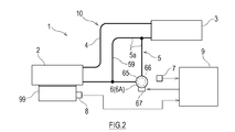
- the heat transport system 1 shown in FIG. 1 includes a loop heat pipe 10, a pump 6 provided on the loop heat pipe 10, an inclination sensor 7, a temperature sensor 8, and a controller 9.
- the loop heat pipe 10 is a natural circulation loop thermosiphon heat pipe.
- the loop heat pipe 10 has a two-phase closed loop formed by the evaporator 2, the steam pipe 4, the condenser 3, and the return liquid pipe 5.
- the non-condensable gas such as air is degassed, and then the working fluid is enclosed.
- the working fluid is not particularly limited, and is a condensable fluid that has been conventionally used as a working fluid for heat pipes (for example, water, alcohol, ammonia, fluorocarbons, hydrofluorocarbons, hydrofluoroethers, and mixtures thereof). May be
- the evaporator 2 includes, for example, a heat transfer plate 21 and a housing 22 in which a working fluid storage chamber 23 is formed.
- the heat transfer plate 21 is thermally connected to the heat source 99 via, for example, thermal grease or a heat transfer sheet.
- the heat source 99 may be, for example, a heating element such as an electronic component.
- the working fluid in the working fluid storage chamber 23 absorbs heat from the heat source 99 via the heat transfer plate 21, and part of it boils and changes to gas. In this way, the two-phase working fluid of boiling vapor and liquid moves in the steam pipe 4 that connects the outlet of the evaporator 2 and the inlet of the condenser 3 due to the pressure difference or buoyancy, and reaches the condenser 3. ..
- the condenser 3 is installed above the evaporator 2.
- a cooling flow path (not shown) is formed in the condenser 3, and the two-phase working fluid radiates heat while passing through the cooling flow path and is cooled and changed to a liquid.
- the liquid-phase working fluid descends by gravity in the liquid pipe 5 that connects the outlet of the condenser 3 and the inlet of the evaporator 2, and returns to the evaporator 2.
- the loop heat pipe 10 described above can switch the working fluid circulation method between a passive mode and an active mode.
- the passive mode the pump 6 is stopped and the working fluid naturally circulates in the loop heat pipe 10 by utilizing the phase change and gravity. That is, in the loop-type heat pipe 10 in the passive mode, the working fluid circulates due to the pressure difference between the heads.
- the active mode the pump 6 is operating, and the working fluid circulates in the loop heat pipe 10 by the circulation driving force given by the pump 6 and gravity.
- the pump 6 is provided in the liquid pipe 5 of the loop heat pipe 10, but the operation of the pump 6 becomes unstable when gas passes therethrough. Therefore, the pump 6 is reliably provided in the downstream portion of the liquid pipe 5 through which the working fluid in the liquid phase flows. It should be provided.
- the working fluid flows into the liquid pipe 5 from the condenser 3 to the evaporator 2 without the action of the pump 6, and when the pump 6 is in operation, the working fluid receives the action of the pump 6.
- the flow path 5a is formed so as to forcibly flow from the condenser 3 to the evaporator 2.
- the pump 6 is defined as a device that gives a driving force (circulation driving force) flowing through the loop heat pipe 10 to the working fluid.
- the pump 6 is not particularly limited, for example, an electric pump 6A (see FIG. 2), a magnetic fluid drive pump 6B (see FIG. 3), or a tank pressure type pump 6C (see FIG. 4) is adopted. You can Further, in the present embodiment, the pump 6 is provided in the liquid pipe 5, but the pump 6 may be provided in the steam pipe 4.
- FIG. 2 is a diagram showing a schematic configuration of a heat transport system 1 that employs an electric pump 6A as the pump 6 of FIG.
- the electric pump 6A shown in FIG. 2 includes a casing 65 arranged in the liquid pipe 5, an impeller 66 housed in the casing 65, and an electric motor 67 for rotationally driving the impeller 66.
- the configuration of the electric pump 6A is not limited to this, and a known electric pump may be adopted.
- the controller 9 controls the driving and stopping of the electric motor 67, that is, the operation and stopping of the electric pump 6A. Since the stopped electric pump 6A impedes the flow of the working fluid, the liquid pipe 5 is provided with a bypass pipe 59 through which the working fluid bypasses the electric pump 6A and flows to the evaporator 2.
- the working fluid in the liquid pipe 5 bypasses the pump 6A in the passive mode and flows through the bypass pipe 59, and is pumped to the evaporator 2 by the pump 6A in the active mode. To be done.
- FIG. 3 is a diagram showing a schematic configuration of a heat transport system 1 that employs a magnetic fluid driven pump 6B as the pump 6 of FIG.
- the magnetic fluid driven pump 6B shown in FIG. 3 includes a heater 62 for heating the working fluid flowing through the liquid pipe 5, and an electromagnet 61 for applying a magnetic field to the working fluid flowing through the liquid pipe 5.
- the electromagnet 61 may be a permanent magnet.
- the controller 9 controls switching between heating and non-heating of the heater 62 and switching between application and non-application of the magnetic field by the electromagnet 61.
- the working fluid is a temperature-sensitive magnetic fluid in which magnetic particles are dispersed in a mother liquor, and has a property that the magnetization remarkably decreases as the temperature rises in a normal temperature range.
- a portion of the liquid pipe 5 heated by the heater 62 is referred to as a heating region, and a portion to which the magnetic field is applied by the electromagnet 61 is referred to as a magnetic field application region.
- the downstream side portion of the magnetism applying area and the upstream side portion of the heating area overlap.
- the side connected to the condenser 3 is the upstream side
- the side connected to the evaporator 2 is the downstream side.
- the non-uniform magnetic field is applied to the magnetic application region by the electromagnet 61, and the magnetic field strength in the magnetic application region is downstream of the maximum position.
- the side is heated by the heater 62. Due to the temperature-sensitive magnetization characteristic of the temperature-sensitive magnetic fluid, the magnitude of magnetization decreases as the temperature rises, and the magnetic volume force decreases. Therefore, the working fluid in the heating region has a magnetic volume force that decreases toward the downstream side, thereby generating a driving force for flowing the working fluid to the downstream side.
- the magnitude of the circulation driving force of the working fluid can be adjusted by the degree of heating (temperature) of the heating region.
- the magnetic application by the electromagnet 61 and the heating by the heater 62 are stopped.
- the working fluid flows through the liquid pipe 5 without any action from the pump 6B.
- the electromagnet 61 is a permanent magnet
- the heating by the heater 62 is stopped, so that the difference in the magneto-volume force between the upstream and the downstream is eliminated, and the circulation of the working fluid is stopped.
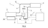
- FIG. 4 is a diagram showing a schematic configuration of a heat transport system 1 that employs a tank pressure pump 6C as the pump 6 of FIG.
- the tank pressure pump 6C shown in FIG. 4 includes a tank 64 provided in the middle of the liquid pipe 5, and a heater 63 provided in the liquid pipe 5 on the upstream side of the tank 64. Switching between heating and non-heating of the heater 63 is controlled by the controller 9.
- the heater 63 heats the working fluid flowing through the liquid pipe 5.
- a part of the working fluid is changed to gas, the working fluid containing bubbles flows into the tank 64, the pressure in the tank 64 rises, and the working fluid is forcibly flown from the tank 64 to the evaporator 2.
- the heating by the heater 63 is stopped.
- the working fluid flows through the liquid pipe 5 without any action from the pump 6C.
- the tilt sensor 7 detects tilt information for measuring the tilt of the loop heat pipe 10 from a predetermined reference posture.
- the loop heat pipe 10 since the working fluid is circulated by the action of gravity, the pressure loss due to the working fluid circulation and the head difference caused by the liquid working fluid being biased toward the condenser 3 rather than the evaporator 2 are balanced.
- the loop heat pipe 10 is installed on a horizontal plane, and the evaporator 2 and the condenser 3 are arranged with a height difference that balances the head difference. Therefore, the reference attitude of the loop heat pipe 10 may be, for example, the attitude of the loop heat pipe 10 when the loop heat pipe 10 is installed on a horizontal plane.
- the inclination sensor 7 may be attached to the loop heat pipe 10 itself.
- the tilt sensor 7 may be attached to an element that behaves integrally with the loop heat pipe 10, such as a floor on which the loop heat pipe 10 is installed.
- a sensor using an acceleration sensor or a gyro sensor is known.
- a general transport aircraft is equipped with a tilt sensor that detects the tilt of the machine and an indicator that displays the tilt of the machine based on the detection value of the tilt sensor. Therefore, when the heat transport system 1 is mounted on a transport machine, the value of an indicator that displays the tilt of the machine body may be used as the tilt information.
- a general transport aircraft is equipped with a controller (for example, a control stick, a steering wheel, etc.) that inputs a command to change the attitude of the aircraft. Therefore, when the heat transport system 1 is mounted on a transport aircraft, the flight control command (levitation command, dive command, descent command, turning command, etc.) of the airframe input to the controller may be used as the tilt information.
- a controller for example, a control stick, a steering wheel, etc.
- the temperature sensor 8 detects temperature information for measuring the temperature of the heat source 99 (that is, a cooling target) that gives heat to the evaporator 2.
- a suitable one for measuring the temperature of the heat source 99 is selected from various kinds of known temperature sensors.
- the controller 9 is electrically connected to the inclination sensor 7 and the temperature sensor 8 in a wired or wireless manner, and acquires detection values of these.
- the controller 9 is electrically connected to the pump 6 in a wired or wireless manner, and controls the operation of the pump 6 by transmitting a control signal to the pump 6.
- the controller 9 is a so-called computer, and includes, for example, an arithmetic processing unit 90a (processor) such as a microcontroller, a CPU, an MPU, a PLC, a DSP, an ASIC, or an FPGA, and a volatile or non-volatile storage device such as a ROM or a RAM. 90b and 90b (both not shown).
- the storage device 90b stores programs executed by the arithmetic processing device, various fixed data, and the like.
- the arithmetic processing device 90a reads out and executes software such as a program stored in the storage device 90b, thereby performing processing for realizing the above-described functional units.
- the controller 9 may execute each process by centralized control by a single computer, or may execute each process by distributed control by cooperation of a plurality of computers.
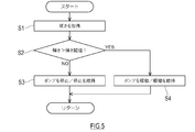
- FIG. 5 is a flowchart showing the flow of the tilt monitoring process by the controller 9.
- the tilt monitoring unit 91 of the controller 9 acquires the tilt information from the tilt sensor 7 (step S1).
- the inclination monitoring unit 91 monitors the inclination of the loop heat pipe 10 by comparing the acquired inclination with a predetermined inclination threshold (step S2).
- the inclination threshold may be set based on the allowable range of the decrease in the heat transfer performance of the loop heat pipe 10.
- dryout a phenomenon in which the working fluid does not return to the evaporator 2 eventually occurs, and heat transfer stops.
- the inclination threshold value may be set so that such a dryout does not occur.
- the inclination threshold is a value specific to the loop heat pipe 10, and is a design value of the loop heat pipe 10 (that is, the structure of the evaporator 2 and the condenser 3, and the height of the evaporator 2 and the condenser 3 in the standard posture). Based on the difference, the length and diameter of the steam pipe 4 and the liquid pipe 5, the amount of working fluid filled, etc.), it is determined in advance by experiment or simulation and is set in the controller 9.
- ⁇ Steady state heat transport system 1 is in passive mode. If the inclination of the loop heat pipe 10 is less than or equal to the inclination threshold (NO in step S2), the heat transport system 1 is set to the passive mode, and the pump 6 is stopped (or stopped) (step S3). On the other hand, if the inclination of the loop heat pipe 10 exceeds the inclination threshold value (YES in step S2), the heat transport system 1 is set to the active mode, and the pump 6 is operated (or the operation is maintained) (step). S4). Specifically, the inclination monitoring unit 91 outputs a signal for operating the pump 6 to the pump control unit 93 when the inclination exceeds the inclination threshold value.
- the pump 6 may apply a circulation driving force to the working fluid so that the circulating flow rate of the working fluid is maintained at a predetermined value.
- the inclination monitoring unit 91 returns the process to step S ⁇ b>1, continues to monitor the inclination of the loop heat pipe 10, and when the calculated inclination becomes less than or equal to the inclination threshold, sends a signal to the pump control unit 93 to stop the pump 6. Output.
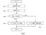
- FIG. 6 is a flowchart showing the flow of temperature monitoring processing by the controller 9.
- the inclination monitoring process and the temperature monitoring process described above may be performed in parallel, or one of the processes may be prioritized.
- the temperature monitoring unit 92 of the controller 9 acquires the temperature information of the heat source 99 from the temperature sensor 8 (step S11), and obtains the temperature of the heat source 99 based on the acquired temperature information (step S12). ..
- the temperature monitoring unit 92 performs the above steps S11 and S12 to acquire the temperature of the heat source 99 from the temperature sensor 8. May be merged as.
- the temperature monitoring unit 92 monitors the temperature of the heat source 99 by comparing the temperature of the heat source 99 with a predetermined temperature threshold value (step S13).
- ⁇ Steady state heat transport system 1 is in passive mode. If the temperature of the heat source 99 is equal to or lower than the temperature threshold value (NO in step S13), the heat transport system 1 is set to the passive mode, and the pump 6 is stopped (or the stop is maintained) (step S14). On the other hand, if the temperature of the heat source 99 exceeds the temperature threshold value (YES in step S13), the heat transport system 1 is set to the active mode and the pump 6 is operated (or operation is maintained) (step S15). Specifically, the temperature monitoring unit 92 outputs a signal for operating the pump 6 to the pump control unit 93 when the acquired temperature exceeds the temperature threshold value. The temperature monitoring unit 92 returns the process to step S11 to continue monitoring the temperature of the heat source 99, and outputs a signal for stopping the pump 6 to the pump control unit 93 when the obtained temperature is equal to or lower than the temperature threshold value.
- the heat transport system 1 is arranged above the evaporator 2 and the evaporator 2 that changes at least a part of the liquid-phase working fluid into gas by receiving heat from the heat source 99.
- a condenser 3 for converting a working fluid in a vapor phase into a liquid
- a vapor pipe 4 connecting an outlet of the evaporator 2 and an inlet of the condenser 3, and an outlet of the condenser 3 and an inlet of the evaporator 2.
- a loop-type heat pipe 10 including a liquid pipe 5 in which a working fluid is sealed, a pump 6 provided in the liquid pipe 5 or the steam pipe 4 for giving a circulating driving force to the working fluid, and a posture of the loop-type heat pipe 10.
- the working fluid in the liquid pipe 5 flows from the condenser 3 to the evaporator 2 without the action of the pump 6 when the pump 6 is stopped, and receives the action of the pump 6 when the pump 6 is in operation. Forced flow from 3 to evaporator 2.
- the controller 9 operates the pump 6 when the inclination exceeds a predetermined inclination threshold, and stops the pump 6 when the inclination is less than or equal to the inclination threshold.
- the controller 9 includes a storage device 90b that stores the tilt monitoring program and the tilt threshold and an arithmetic processing device 90a that executes the tilt monitoring program, and the tilt monitoring program causes the arithmetic processing device 90a to have a predetermined tilt.
- the tilt monitoring program causes the arithmetic processing device 90a to have a predetermined tilt.
- the pump 6 when the inclination of the posture of the loop heat pipe 10 is less than or equal to the threshold value, that is, during steady operation, the pump 6 is stopped and the working fluid does not require external energy. Goes around the loop heat pipe 10.
- the circulation driving force of the working fluid due to gravity decreases, but the circulation driving force is applied to the working fluid by the pump 6 so as to compensate for it. In this way, in the heat transport system 1, the working fluid circulates stably regardless of the change in the posture of the loop heat pipe 10, so that a stable heat transport amount can be obtained.
- the heat transport system 1 may further include a temperature sensor 8 that detects the temperature of the heat source 99 that gives heat to the working fluid of the evaporator 2.
- the controller 9 acquires the temperature of the heat source 99 from the temperature sensor 8, operates the pump 6 when the temperature exceeds a predetermined temperature threshold, and stops the pump 6 when the temperature is equal to or lower than the temperature threshold.
- the driving force is applied to the working fluid by the pump 6 so as to compensate for the insufficient circulation flow rate.
- the circulation flow rate of the working fluid is increased, and the heat transport amount of the heat transport system 1 can be increased.
- the heat transfer characteristic of the heat transport system 1 can be improved, and the heat source 99 can be reliably cooled to a desired temperature.
- the pump 6 is the electric pump 6A provided in the liquid pipe 5, and the liquid pipe 5 bypasses the pump 6 to supply the working fluid.
- a drain bypass tube 59 may be included. ..
- the working fluid is a temperature-sensitive magnetic fluid
- the pump 6B is a magnet that applies a non-uniform magnetic field to the working fluid flowing through the liquid pipe 5.
- 61 and a heater 62 that heats the working fluid magnetized by applying a magnetic field.
- the stopped pump 6B does not act on the working fluid flowing through the liquid pipe 5 in which the pump 6B is installed. Therefore, compared with the case where the bypass pipe 59 that bypasses the pump 6A is provided, the pressure loss can be suppressed, and as a result, the heat transfer characteristics of the heat transport system 1 can be improved. Further, the working fluid does not come into direct contact with the magnet 61 and the heater 62, and since there is no mechanical drive unit, maintenance is easy and durability is high. In addition, the pump 6B having the above-mentioned configuration saves electric power as compared with the case where an electric pump is used.
- the pump 6C includes the tank 64 provided in the middle of the liquid pipe and the inside of the tank 64 or the upstream side of the flow of the working fluid from the tank 64. And a heater 63 provided in the above, and a circulation driving force may be given to the working fluid by the pressure of the steam generated by the heating of the heater 63.
- the stopped pump 6C does not act on the working fluid flowing through the liquid pipe 5 in which the pump 6C is installed. Therefore, compared with the case where the bypass pipe 59 that bypasses the pump 6A is provided, the pressure loss can be suppressed, and as a result, the heat transfer characteristics of the heat transport system 1 can be improved. Further, since the pump 6C does not include a drive unit, maintenance is easy and the pump 6C has a long life.
- the inclination monitoring process and the temperature monitoring process may be performed independently in the heat transport system 1, but by combining these processes, the heat transport amount of the loop heat pipe 10 can be more economically achieved. It is possible to stabilize the cooling capacity of the heat source 99 by the evaporator 2.
- FIG. 7 is a flowchart showing a modified example of the flow of tilt monitoring processing by the controller 9. It should be noted that the storage unit of the controller 9 stores the inclination threshold value, the first temperature threshold value, and the second temperature threshold value in advance.
- the tilt monitoring unit 91 of the controller 9 acquires the tilt information from the tilt sensor 7 (step S31).
- the inclination monitoring unit 91 monitors the inclination of the loop heat pipe 10 by comparing the acquired inclination with a predetermined inclination threshold (step S32).
- the inclination monitoring unit 91 acquires the temperature of the heat source 99 from the temperature sensor 8 (step S33), and determines the temperature of the heat source 99 and the predetermined first value. It is compared with the temperature threshold of (step S34). If the temperature of the heat source 99 exceeds the first temperature threshold value (YES in step S34), the inclination monitoring unit 91 outputs a signal for operating the pump 6 to the pump control unit 93 (step S35), and the process is performed. Return to step S31.
- step S34 If the temperature of the heat source 99 is equal to or lower than the first temperature threshold value (NO in step S34), the inclination monitoring unit 91 outputs a signal for stopping the pump 6 to the pump control unit 93 (step S36), and the process is step S31. Return to.
- the inclination monitoring unit 91 acquires the temperature of the heat source 99 from the temperature sensor 8 (step S37), and determines the temperature of the heat source 99 and the predetermined value.
- the temperature threshold value of 2 is compared (step S38). If the temperature of the heat source 99 exceeds the ninth temperature threshold value (YES in step S38), the inclination monitoring unit 91 outputs a signal for operating the pump 6 to the pump control unit 93 (step S39), and the process is performed. Return to step S31.
- the inclination monitoring unit 91 outputs a signal for stopping the pump 6 to the pump control unit 93 (step S40), and the process is performed. Return to S31.
- the heat transporting capacity is lower than when the inclination is equal to or smaller than the inclination threshold, and therefore, when the temperature of the heat source 99 is lower than that in the latter case,
- the circulation driving force may be assisted by the pump 6 to enhance the heat transport capacity. Therefore, it is desirable that the first temperature threshold value is equal to or lower than the second temperature threshold value. As a result, the pump 6 can be operated before the circulation driving force of the working medium is reduced and the heat source 99 is insufficiently cooled, so that an excessive temperature rise of the heat source 99 can be prevented.
- the controller 9 of the heat transport system 1 operates the pump 6 if the temperature of the heat source 99 exceeds the predetermined first temperature threshold value when the inclination exceeds the predetermined inclination threshold value, If the temperature of the heat source 99 is less than or equal to the first temperature threshold, the pump 6 is stopped, and if the gradient is less than or equal to the predetermined gradient threshold, and if the temperature of the heat source 99 exceeds the predetermined second temperature threshold, the pump 6 is stopped. When the temperature of the heat source 99 is equal to or lower than the second temperature threshold, the pump 6 is stopped.
- the controller 9 stores the tilt monitoring program according to the modified example, the tilt threshold, the first temperature threshold, and the second temperature threshold, and the arithmetic processing unit 90a that executes the tilt monitoring program according to the modified example.
- the inclination monitoring program according to the modified example includes a pump 6 for the arithmetic processing unit 90a if the temperature of the heat source 99 exceeds a predetermined first temperature threshold when the inclination exceeds a predetermined inclination threshold.
- the pump 6 is stopped, and when the inclination is equal to or lower than the predetermined inclination threshold, the temperature of the heat source 99 exceeds the predetermined second temperature threshold. If so, the pump 6 is operated, and if the temperature of the heat source 99 is equal to or lower than the second temperature threshold, the pump 6 is stopped.
- the heat transport system 1 described above even if the inclination of the posture of the loop heat pipe 10 exceeds the inclination threshold value, if the temperature of the heat source 99 is equal to or lower than the first temperature threshold value, the cooling is considered sufficient and the pump By stopping or continuing the stop 6, the working fluid goes around the loop heat pipe without the need for external energy. Therefore, the heat transfer amount of the loop heat pipe 10 can be stabilized more economically.
- the pump 6 is operated if the temperature of the heat source 99 exceeds the second temperature threshold value. The circulating driving force of the working medium is assisted by allowing or continuing the operation.
- the cooling capacity of the heat source 99 by the evaporator 2 can be stabilized.
- external energy is required to operate the pump 6, but the pump 6 operates only under a predetermined condition and stops at other times. It is possible to suppress the consumption of external energy as compared with the case where the plant always operates. Therefore, in the heat transport system 1 described above, it is possible to achieve stable heat transfer characteristics even when the posture of the loop heat pipe 10 changes, and to suppress the consumption of external energy.
- FIG. 8 is a figure which shows the example which applied the heat transport system 1 to the aircraft 50 as an example of a transport machine.
- FIG. 8 shows a part of the fuselage 51 and the main wing 53 of the aircraft 50.
- the body 51 has a multi-layer structure including an outer plate 52 and an inner wall 54 provided on the passenger side of the outer plate 52.
- a cooling chamber 55 is formed between the outer plate 52 and the inner wall 54.
- the inside of the cooling chamber 55 is at a low temperature due to the cold heat transmitted from the outer plate 52 that is exposed to the outside air (an example of an external fluid) that is significantly colder than the ground during flight.
- the outer plate 52 may be provided with an air inlet and an air outlet that communicate with the cooling chamber 55, and ram air may be introduced into the cooling chamber 55 during flight.
- a fuel tank 57 is provided inside the main wing 53 which is exposed to the outside air whose temperature is significantly lower than that of the ground during flight. The fuel tank 57 and the fuel stored therein are cooled by the outside air.
- the aircraft 50 is equipped with two sets of heat transport system 1.
- the one heat transport system 1 is for cooling the heat source 99 installed on the floor of the body 51, and the evaporator 2 thermally connected to the heat source 99 and the condenser arranged in the cooling chamber 55. It includes a vaporizer 3, a vapor pipe 4 and a liquid pipe 5 that connect between the evaporator 2 and the condenser 3, and a pump 6 provided in the liquid pipe 5.
- a fan 56 for forcibly ventilating the condenser 3 is provided inside the cooling chamber 55.
- the condenser 3 radiates heat to the gas in the cooling chamber 55 that is cooled by the outside air. In other words, in the condenser 3, the working fluid can be condensed by using the cold heat of the outside air.
- the outside air becomes significantly lower than the room temperature during flight, so the temperature of the heat source 99 to which the evaporator 2 is thermally connected and the medium (gas in the cooling chamber 55) radiated by the condenser 3 are radiated.
- the difference becomes large, and the heat transport system 1 can perform highly efficient heat transport.
- the other heat transport system 1 is for cooling the heat source 99 installed under the floor in the body 51, and includes the evaporator 2 thermally connected to the heat source 99 and the liquid phase in the fuel tank 57. It includes a condenser 3 arranged inside, a vapor pipe 4 and a liquid pipe 5 connecting between the evaporator 2 and the condenser 3, and a pump 6 provided in the liquid pipe 5.
- the condenser 3 radiates heat to the fuel cooled by the outside air. In other words, in the condenser 3, the working fluid can be condensed by using the cold heat of the outside air.
- the outside air becomes significantly lower than room temperature during flight, so that the temperature difference between the heat source 99 to which the evaporator 2 is thermally connected and the medium (fuel) radiated by the condenser 3 becomes large,
- the heat transport system 1 can perform highly efficient heat transport.
- the fuel tank 57 does not have to actively exchange heat with the external fluid.
- the transport device for example, the aircraft 50
- the transport device includes the heat source 99 and the heat transport system 1 including the evaporator 2 that evaporates the working fluid by receiving heat from the heat source 99.
- the working fluid circulates stably and a stable heat transport amount is obtained regardless of the change in the posture of the loop heat pipe 10. Therefore, such a heat transport system 1 is suitable for cooling the heat source 99 mounted on a transport machine whose posture changes sequentially.
- the heat source 99 is not particularly limited, but for example, electronic devices including heat generating parts such as a control panel, an engine control unit (ECU), and other computers, mechanical parts that generate frictional heat such as bearings, and heat generation such as batteries. Body, cabin air, etc.
- the transport machine has an outer plate 52 exposed to an external fluid, and an inner wall 54 arranged inside the outer plate 52.
- the condenser 3 may be arranged in the cooling chamber 55 formed therebetween.
- the working fluid can be condensed by using the cold heat of the external fluid (outside air).
- the temperature difference between the heat source 99 to which the evaporator 2 is thermally connected and the medium radiated by the condenser 3 becomes large, and
- the transportation system 1 can perform highly efficient heat transportation.
- the transport machine may include the fuel tank 57, and the condenser 3 may be arranged in the liquid phase of the fuel tank 57.
- the working fluid can be condensed by using the fuel tank 57 having a large heat capacity.
- the fuel tank 57 actively exchanges heat with a low temperature external fluid, the temperature difference between the heat source 99 to which the evaporator 2 is thermally connected and the medium radiated by the condenser 3 becomes large,
- the heat transport system 1 can perform more efficient heat transport.
- the loop heat pipe 10 of the above embodiment is not limited to the thermosiphon type, but a wick type may be adopted.
- a wick type In the wick type loop heat pipe, in order to recirculate the working fluid from the condenser 3 to the evaporator 2, the capillary force of the working fluid in the wick is used, but gravity is also used. Therefore, even when the present invention is applied to the heat transport system including the wick type loop heat pipe, the same effect as described above can be obtained.
- Heat transport system 2 Evaporator 3: Condenser 4: Steam pipe 5: Liquid pipe 5a: Flow path 6: Pump 7: Inclination sensor 8: Temperature sensor 9: Controller 90a: Processor 89b: Storage device 10: Loop type heat pipe 21: Heat transfer plate 22: Housing 23: Working fluid storage chamber 50: Aircraft (an example of transport aircraft) 51: body 52: outer plate 53: main wing 54: inner wall 55: cooling chamber 56: fan 57: fuel tank 59: bypass pipe 61: electromagnets 62, 63: heater 64: tank 65: casing 66: impeller 67: electric motor 91: Inclination monitoring unit 92: Temperature monitoring unit 93: Pump control unit 99: Heat source
Landscapes
- Engineering & Computer Science (AREA)
- Mechanical Engineering (AREA)
- Thermal Sciences (AREA)
- Physics & Mathematics (AREA)
- Aviation & Aerospace Engineering (AREA)
- General Engineering & Computer Science (AREA)
- Life Sciences & Earth Sciences (AREA)
- Sustainable Development (AREA)
- Microelectronics & Electronic Packaging (AREA)
- Health & Medical Sciences (AREA)
- General Health & Medical Sciences (AREA)
- Pulmonology (AREA)
- Air Conditioning Control Device (AREA)
- Other Air-Conditioning Systems (AREA)
Abstract
La présente invention vise à atteindre à la fois l'obtention d'une quantité stable de transfert de chaleur même si la position d'un caloduc de type en boucle change, et la suppression de consommation d'énergie externe, dans un système de transfert de chaleur utilisant un caloduc de type en boucle et dans des machines de transfert comprenant ledit système de transfert de chaleur. Ce système de transfert de chaleur comprend : un caloduc de type en boucle fermée à deux phases ; une pompe qui est disposée sur un tuyau de liquide ou un tuyau de vapeur du caloduc de type en boucle, et fournit une force d'entraînement en circulation à un fluide de travail ; un capteur d'inclinaison qui détecte l'inclinaison de la position du caloduc de type en boucle ; et un dispositif de commande qui amène la pompe à fonctionner lorsque l'inclinaison dépasse une valeur seuil d'inclinaison prescrite, et amène la pompe à s'arrêter lorsque l'inclinaison est inférieure ou égale à la valeur seuil d'inclinaison.
Priority Applications (2)
| Application Number | Priority Date | Filing Date | Title |
|---|---|---|---|
| EP19901815.1A EP3904811B1 (fr) | 2018-12-27 | 2019-12-24 | Système de transfert de chaleur et machines de transfert |
| US17/418,248 US12000658B2 (en) | 2018-12-27 | 2019-12-24 | Heat transport system and transportation machine |
Applications Claiming Priority (2)
| Application Number | Priority Date | Filing Date | Title |
|---|---|---|---|
| JP2018245270A JP7205970B2 (ja) | 2018-12-27 | 2018-12-27 | 熱輸送システム及び輸送機 |
| JP2018-245270 | 2018-12-27 |
Publications (1)
| Publication Number | Publication Date |
|---|---|
| WO2020138077A1 true WO2020138077A1 (fr) | 2020-07-02 |
Family
ID=71125713
Family Applications (1)
| Application Number | Title | Priority Date | Filing Date |
|---|---|---|---|
| PCT/JP2019/050595 Ceased WO2020138077A1 (fr) | 2018-12-27 | 2019-12-24 | Système de transfert de chaleur et machines de transfert |
Country Status (4)
| Country | Link |
|---|---|
| US (1) | US12000658B2 (fr) |
| EP (1) | EP3904811B1 (fr) |
| JP (1) | JP7205970B2 (fr) |
| WO (1) | WO2020138077A1 (fr) |
Families Citing this family (3)
| Publication number | Priority date | Publication date | Assignee | Title |
|---|---|---|---|---|
| US20220346279A1 (en) * | 2021-04-21 | 2022-10-27 | Aic Inc. | Temperature controlling method of liquid cooling device |
| US12576693B2 (en) * | 2024-01-12 | 2026-03-17 | Toyota Motor Engineering & Manufacturing North America, Inc. | Cooling systems and assemblies, and vehicles including the same |
| JP2025124335A (ja) * | 2024-02-14 | 2025-08-26 | 三菱重工業株式会社 | 冷却システム |
Citations (10)
| Publication number | Priority date | Publication date | Assignee | Title |
|---|---|---|---|---|
| JPS60159565A (ja) * | 1984-01-26 | 1985-08-21 | 株式会社島津製作所 | ヒ−トパイプ熱交換器を有する航空機用空調装置 |
| JPH01111197A (ja) * | 1987-10-23 | 1989-04-27 | Akutoronikusu Kk | 熱伝達装置 |
| JPH0539963A (ja) * | 1991-08-02 | 1993-02-19 | Sanki Eng Co Ltd | 冷暖房装置 |
| JPH10231814A (ja) * | 1997-02-18 | 1998-09-02 | Tdk Corp | 流体の流れ制御方法および流体の流れ制御装置 |
| JPH11183066A (ja) * | 1997-12-24 | 1999-07-06 | Toshiba Corp | 熱輸送用ヒートパイプ装置 |
| JP2003314910A (ja) * | 2002-04-24 | 2003-11-06 | Matsushita Electric Ind Co Ltd | 半導体素子冷却装置およびその制御方法 |
| JP2013191545A (ja) * | 2012-01-24 | 2013-09-26 | Boeing Co:The | 航空機応用のための相変化材料、ヒートパイプ、及び燃料電池の利用 |
| JP2014134335A (ja) * | 2013-01-09 | 2014-07-24 | Kri Inc | 磁性流体駆動装置並びにそれを用いた熱輸送装置及び動力発生装置 |
| JP2017017199A (ja) | 2015-07-01 | 2017-01-19 | 富士通株式会社 | 冷却部品及び電子機器 |
| WO2018047529A1 (fr) * | 2016-09-09 | 2018-03-15 | 株式会社デンソー | Appareil de réglage de température de dispositif |
Family Cites Families (8)
| Publication number | Priority date | Publication date | Assignee | Title |
|---|---|---|---|---|
| IN147351B (fr) * | 1976-01-16 | 1980-02-09 | Rilett John W | |
| JPS62112991A (ja) * | 1985-11-13 | 1987-05-23 | Gadelius Kk | 熱交換器とその運転方法 |
| US5725049A (en) * | 1995-10-31 | 1998-03-10 | The United States Of America As Represented By The Administrator Of The National Aeronautics And Space Administration | Capillary pumped loop body heat exchanger |
| US20080264068A1 (en) * | 2004-12-03 | 2008-10-30 | Shinichi Nakasuka | Magnetic Convection Heat Circulation Pump |
| US20060162903A1 (en) * | 2005-01-21 | 2006-07-27 | Bhatti Mohinder S | Liquid cooled thermosiphon with flexible partition |
| US9146059B2 (en) * | 2012-05-16 | 2015-09-29 | The United States Of America, As Represented By The Secretary Of The Navy | Temperature actuated capillary valve for loop heat pipe system |
| JP6737241B2 (ja) * | 2017-06-16 | 2020-08-05 | 株式会社デンソー | サーモサイフォン |
| JP7159771B2 (ja) * | 2017-12-22 | 2022-10-25 | 株式会社デンソー | 機器温調装置 |
-
2018
- 2018-12-27 JP JP2018245270A patent/JP7205970B2/ja active Active
-
2019
- 2019-12-24 WO PCT/JP2019/050595 patent/WO2020138077A1/fr not_active Ceased
- 2019-12-24 US US17/418,248 patent/US12000658B2/en active Active
- 2019-12-24 EP EP19901815.1A patent/EP3904811B1/fr active Active
Patent Citations (10)
| Publication number | Priority date | Publication date | Assignee | Title |
|---|---|---|---|---|
| JPS60159565A (ja) * | 1984-01-26 | 1985-08-21 | 株式会社島津製作所 | ヒ−トパイプ熱交換器を有する航空機用空調装置 |
| JPH01111197A (ja) * | 1987-10-23 | 1989-04-27 | Akutoronikusu Kk | 熱伝達装置 |
| JPH0539963A (ja) * | 1991-08-02 | 1993-02-19 | Sanki Eng Co Ltd | 冷暖房装置 |
| JPH10231814A (ja) * | 1997-02-18 | 1998-09-02 | Tdk Corp | 流体の流れ制御方法および流体の流れ制御装置 |
| JPH11183066A (ja) * | 1997-12-24 | 1999-07-06 | Toshiba Corp | 熱輸送用ヒートパイプ装置 |
| JP2003314910A (ja) * | 2002-04-24 | 2003-11-06 | Matsushita Electric Ind Co Ltd | 半導体素子冷却装置およびその制御方法 |
| JP2013191545A (ja) * | 2012-01-24 | 2013-09-26 | Boeing Co:The | 航空機応用のための相変化材料、ヒートパイプ、及び燃料電池の利用 |
| JP2014134335A (ja) * | 2013-01-09 | 2014-07-24 | Kri Inc | 磁性流体駆動装置並びにそれを用いた熱輸送装置及び動力発生装置 |
| JP2017017199A (ja) | 2015-07-01 | 2017-01-19 | 富士通株式会社 | 冷却部品及び電子機器 |
| WO2018047529A1 (fr) * | 2016-09-09 | 2018-03-15 | 株式会社デンソー | Appareil de réglage de température de dispositif |
Non-Patent Citations (1)
| Title |
|---|
| See also references of EP3904811A4 |
Also Published As
| Publication number | Publication date |
|---|---|
| US12000658B2 (en) | 2024-06-04 |
| JP2020106205A (ja) | 2020-07-09 |
| EP3904811A4 (fr) | 2022-09-14 |
| EP3904811A1 (fr) | 2021-11-03 |
| EP3904811B1 (fr) | 2025-04-30 |
| JP7205970B2 (ja) | 2023-01-17 |
| US20220090866A1 (en) | 2022-03-24 |
Similar Documents
| Publication | Publication Date | Title |
|---|---|---|
| JP4673856B2 (ja) | 航空機の内部に位置する熱源から熱を排出させる冷却システム及び方法 | |
| WO2020138077A1 (fr) | Système de transfert de chaleur et machines de transfert | |
| JP6375109B2 (ja) | 熱伝導率が高く再利用可能な熱防護システム | |
| EP2501573B1 (fr) | Système de refroidissement pour au moins une batterie dans un véhicule | |
| CN109690221B (zh) | 设备温度调节装置 | |
| JP6917124B2 (ja) | 航空機の中央翼タンク用の冷却システム | |
| US20120152186A1 (en) | System, method, and apparatus for integrated hybrid power system thermal management | |
| JP2007519555A5 (fr) | ||
| JP7028191B2 (ja) | バルブ制御装置、冷却装置およびバルブ制御方法 | |
| US20210370798A1 (en) | System for cooling a battery of a motor vehicle, and motor vehicle | |
| CN110892225B (zh) | 设备温度调节装置 | |
| KR102835221B1 (ko) | 전기 자동차의 열 관리 시스템을 위한 열 회로 | |
| WO2020138080A1 (fr) | Évaporateur et caloduc de type boucle | |
| US10123457B2 (en) | Cooling apparatus and electronic device | |
| JP7535392B2 (ja) | 蒸発器及びループ型ヒートパイプ | |
| US20220065548A1 (en) | Loop heat pipe and transportation machine | |
| CN103373469A (zh) | 飞行器热控制系统及操作飞行器热控制系统的方法 | |
| JP2010206892A (ja) | インバータの冷却装置 | |
| EP3904813A1 (fr) | Caloduc à boucle et transporteur | |
| Hoang et al. | Hybrid two-phase mechanical/capillary pumped loop for high-capacity heat transport | |
| JP2017067305A (ja) | 熱輸送システム | |
| US9914545B2 (en) | Aircraft heat exchange system including a thermoelectric device | |
| US20260036376A1 (en) | Pulsating heat pipe with wettability gradient to provide unidirectional flow | |
| US20220090867A1 (en) | Evaporator and loop heat pipe | |
| JP2001097285A (ja) | 高速走行体の熱交換器 |
Legal Events
| Date | Code | Title | Description |
|---|---|---|---|
| 121 | Ep: the epo has been informed by wipo that ep was designated in this application |
Ref document number: 19901815 Country of ref document: EP Kind code of ref document: A1 |
|
| NENP | Non-entry into the national phase |
Ref country code: DE |
|
| ENP | Entry into the national phase |
Ref document number: 2019901815 Country of ref document: EP Effective date: 20210727 |
|
| WWG | Wipo information: grant in national office |
Ref document number: 2019901815 Country of ref document: EP |