WO2020138080A1 - Évaporateur et caloduc de type boucle - Google Patents
Évaporateur et caloduc de type boucle Download PDFInfo
- Publication number
- WO2020138080A1 WO2020138080A1 PCT/JP2019/050598 JP2019050598W WO2020138080A1 WO 2020138080 A1 WO2020138080 A1 WO 2020138080A1 JP 2019050598 W JP2019050598 W JP 2019050598W WO 2020138080 A1 WO2020138080 A1 WO 2020138080A1
- Authority
- WO
- WIPO (PCT)
- Prior art keywords
- working fluid
- evaporator
- housing
- heat
- fluid outlet
- Prior art date
- Legal status (The legal status is an assumption and is not a legal conclusion. Google has not performed a legal analysis and makes no representation as to the accuracy of the status listed.)
- Ceased
Links
Images



Classifications
-
- H—ELECTRICITY
- H05—ELECTRIC TECHNIQUES NOT OTHERWISE PROVIDED FOR
- H05K—PRINTED CIRCUITS; CASINGS OR CONSTRUCTIONAL DETAILS OF ELECTRIC APPARATUS; MANUFACTURE OF ASSEMBLAGES OF ELECTRICAL COMPONENTS
- H05K7/00—Constructional details common to different types of electric apparatus
- H05K7/20—Modifications to facilitate cooling, ventilating, or heating
- H05K7/2029—Modifications to facilitate cooling, ventilating, or heating using a liquid coolant with phase change in electronic enclosures
- H05K7/20336—Heat pipes, e.g. wicks or capillary pumps
-
- F—MECHANICAL ENGINEERING; LIGHTING; HEATING; WEAPONS; BLASTING
- F28—HEAT EXCHANGE IN GENERAL
- F28D—HEAT-EXCHANGE APPARATUS, NOT PROVIDED FOR IN ANOTHER SUBCLASS, IN WHICH THE HEAT-EXCHANGE MEDIA DO NOT COME INTO DIRECT CONTACT
- F28D15/00—Heat-exchange apparatus with the intermediate heat-transfer medium in closed tubes passing into or through the conduit walls ; Heat-exchange apparatus employing intermediate heat-transfer medium or bodies
- F28D15/02—Heat-exchange apparatus with the intermediate heat-transfer medium in closed tubes passing into or through the conduit walls ; Heat-exchange apparatus employing intermediate heat-transfer medium or bodies in which the medium condenses and evaporates, e.g. heat pipes
- F28D15/0266—Heat-exchange apparatus with the intermediate heat-transfer medium in closed tubes passing into or through the conduit walls ; Heat-exchange apparatus employing intermediate heat-transfer medium or bodies in which the medium condenses and evaporates, e.g. heat pipes with separate evaporating and condensing chambers connected by at least one conduit; Loop-type heat pipes; with multiple or common evaporating or condensing chambers
-
- F—MECHANICAL ENGINEERING; LIGHTING; HEATING; WEAPONS; BLASTING
- F28—HEAT EXCHANGE IN GENERAL
- F28D—HEAT-EXCHANGE APPARATUS, NOT PROVIDED FOR IN ANOTHER SUBCLASS, IN WHICH THE HEAT-EXCHANGE MEDIA DO NOT COME INTO DIRECT CONTACT
- F28D15/00—Heat-exchange apparatus with the intermediate heat-transfer medium in closed tubes passing into or through the conduit walls ; Heat-exchange apparatus employing intermediate heat-transfer medium or bodies
- F28D15/02—Heat-exchange apparatus with the intermediate heat-transfer medium in closed tubes passing into or through the conduit walls ; Heat-exchange apparatus employing intermediate heat-transfer medium or bodies in which the medium condenses and evaporates, e.g. heat pipes
- F28D15/025—Heat-exchange apparatus with the intermediate heat-transfer medium in closed tubes passing into or through the conduit walls ; Heat-exchange apparatus employing intermediate heat-transfer medium or bodies in which the medium condenses and evaporates, e.g. heat pipes having non-capillary condensate return means
-
- H—ELECTRICITY
- H05—ELECTRIC TECHNIQUES NOT OTHERWISE PROVIDED FOR
- H05K—PRINTED CIRCUITS; CASINGS OR CONSTRUCTIONAL DETAILS OF ELECTRIC APPARATUS; MANUFACTURE OF ASSEMBLAGES OF ELECTRICAL COMPONENTS
- H05K7/00—Constructional details common to different types of electric apparatus
- H05K7/20—Modifications to facilitate cooling, ventilating, or heating
- H05K7/2029—Modifications to facilitate cooling, ventilating, or heating using a liquid coolant with phase change in electronic enclosures
- H05K7/20309—Evaporators
-
- H—ELECTRICITY
- H10—SEMICONDUCTOR DEVICES; ELECTRIC SOLID-STATE DEVICES NOT OTHERWISE PROVIDED FOR
- H10W—GENERIC PACKAGES, INTERCONNECTIONS, CONNECTORS OR OTHER CONSTRUCTIONAL DETAILS OF DEVICES COVERED BY CLASS H10
- H10W40/00—Arrangements for thermal protection or thermal control
- H10W40/70—Fillings or auxiliary members in containers or in encapsulations for thermal protection or control
- H10W40/73—Fillings or auxiliary members in containers or in encapsulations for thermal protection or control for cooling by change of state
-
- F—MECHANICAL ENGINEERING; LIGHTING; HEATING; WEAPONS; BLASTING
- F28—HEAT EXCHANGE IN GENERAL
- F28D—HEAT-EXCHANGE APPARATUS, NOT PROVIDED FOR IN ANOTHER SUBCLASS, IN WHICH THE HEAT-EXCHANGE MEDIA DO NOT COME INTO DIRECT CONTACT
- F28D15/00—Heat-exchange apparatus with the intermediate heat-transfer medium in closed tubes passing into or through the conduit walls ; Heat-exchange apparatus employing intermediate heat-transfer medium or bodies
- F28D15/02—Heat-exchange apparatus with the intermediate heat-transfer medium in closed tubes passing into or through the conduit walls ; Heat-exchange apparatus employing intermediate heat-transfer medium or bodies in which the medium condenses and evaporates, e.g. heat pipes
- F28D2015/0216—Heat-exchange apparatus with the intermediate heat-transfer medium in closed tubes passing into or through the conduit walls ; Heat-exchange apparatus employing intermediate heat-transfer medium or bodies in which the medium condenses and evaporates, e.g. heat pipes having particular orientation, e.g. slanted, or being orientation-independent
Definitions
- the present invention relates to an evaporator and a loop heat pipe including the evaporator.
- loop type heat pipe that carries out high density heat transport using the phase change of the working fluid.
- a heat transport system using such a loop heat pipe has been used for cooling electronic devices such as computers and home appliances.
- As a loop heat pipe there is one that circulates a working fluid by utilizing capillary force and/or gravity.
- the loop-type heat pipe has a closed loop formed by an evaporator, a condenser, a vapor pipe connecting the evaporator and the condenser, and a liquid pipe connecting the condenser and the evaporator.
- the working fluid is enclosed in the closed loop.
- the liquid-phase working fluid is heated by the heat transmitted from the heating element, and a part of the working fluid is changed to gas.
- the gas-liquid two-phase working fluid moves in the steam pipe due to the pressure difference and buoyancy, and reaches the condenser.
- the condenser the working fluid is cooled and converted into a liquid.
- the liquid-phase working fluid is returned to the evaporator by capillary force and/or gravity. In this way, in the loop heat pipe, the working fluid circulates in the two-phase closed loop, whereby the heat is transported from the evaporator to the condenser, and the heating element thermally connected to the evaporator is cooled.
- Patent Documents 1 to 4 propose, as an evaporator used in the above loop heat pipe, one having a rectangular parallelepiped shape having the largest front and rear surfaces.
- This evaporator has a heat receiving body provided on the front and rear surfaces of a rectangular parallelepiped, and fins projecting from the heat receiving body into the evaporator, and a working fluid is provided below a side surface sandwiched between the front surface and the rear surface of the evaporator.
- An inlet is provided and a working fluid outlet is provided on top of the same side.
- a liquid-phase working fluid exists inside the evaporator included in the loop heat pipe, and a vapor-phase working fluid or a gas-liquid two-phase working fluid exists above the liquid-phase working fluid.
- the working fluid outlet of the evaporator may be below the liquid level.
- the flow rate of the working fluid flowing out from the working fluid outlet is reduced, the driving force for circulating the working fluid is reduced, and the heat transfer amount of the loop heat pipe is reduced.
- the present invention has been made in view of the above circumstances, and an object of the present invention is to provide an evaporator and a loop heat pipe including the same, and to provide a working fluid flowing out of the evaporator even if the attitude of the evaporator changes. It is about proposing things that make it difficult for the flow to stop.
- An evaporator is an evaporator that evaporates at least a part of a working fluid by receiving heat from a heat source,
- a housing having a plurality of surfaces having at least one of a front surface and a rear surface having a maximum area;
- a heat receiving body that is provided on at least one of the front surface and the rear surface and is thermally connected to the heat source,
- the casing has at least one working fluid inlet provided on a surface other than its upper surface, and at least one working fluid outlet provided on its upper surface at both ends in the longitudinal direction.
- the virtual liquid surface is defined as a boundary surface in which the volume ratio (void ratio) of the gas in the gas-liquid two-phase flow becomes a predetermined ratio (for example, 50%) in the housing of the evaporator.
- An evaporator is an evaporator that is mounted on a transport machine having a tilt allowable angle of ⁇ ° and that evaporates at least a part of a working fluid by receiving heat from a heat source,
- a housing having a plurality of surfaces whose front and rear surfaces have the largest area;
- a heat receiving body that is provided on at least one of the front surface and the rear surface and is thermally connected to the heat source,
- the housing has at least one working fluid inlet provided on a surface other than its upper surface, and at least one working fluid outlet provided on a central portion of its upper surface, When the housing placed on a horizontal plane is viewed from the front side thereof, the working fluid outlet is provided when an intersection of a horizontal plane passing through the upper end of the heat receiving body and a vertical line passing through the center of the upper surface of the housing is defined as a reference point.
- the angle formed by the straight line connecting the center point of the opening and the reference point and the horizontal plane is ⁇ ° or more and 90° or less.
- the working fluid outlet of the evaporator does not fall below the virtual liquid level even if the posture of the evaporator tilts within an allowable tilt angle of the transportation machine. Therefore, even if the posture of the evaporator is changed, the vapor-phase or two-phase working fluid flows out smoothly from the working fluid outlet located at or above the virtual liquid level.
- a loop heat pipe includes an evaporator that changes at least a part of a liquid-phase working fluid into a gas, and a condenser that changes the gas-phase working fluid into a liquid.
- the vapor-phase or two-phase working fluid flows out smoothly from the working fluid outlet located at or above the virtual liquid level. Therefore, in the loop heat pipe including such an evaporator, even if the posture thereof is changed, the circulation of the working fluid is not delayed, and a stable heat transfer amount can be obtained.
- an evaporator and a loop-type heat pipe including the same, in which the flow of a vapor phase or two-phase working fluid from the evaporator is less likely to be delayed even when the attitude of the evaporator is changed. be able to.
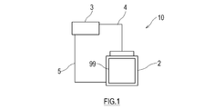
- FIG. 1 is a diagram showing a schematic configuration of a loop heat pipe according to an embodiment of the present invention.
- FIG. 2 is a perspective view of a vertically installed evaporator according to the first embodiment.
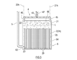
- FIG. 3 is a diagram for explaining the internal structure of the evaporator shown in FIG.
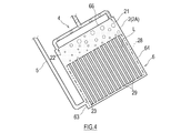
- FIG. 4 is a diagram showing a state in which the evaporator shown in FIG. 2 is tilted.
- FIG. 5 is a diagram showing an aircraft equipped with a vertically installed evaporator according to the second embodiment.
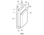
- FIG. 6 is a perspective view of a vertically installed evaporator according to the second embodiment.
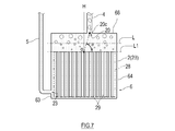
- FIG. 7: is a figure explaining the internal structure of the evaporator shown in FIG.
- FIG. 8 is a diagram showing a state in which the evaporator shown in FIG. 6 is tilted.
- FIG. 1 is a diagram showing a schematic configuration of a loop heat pipe 10 according to an embodiment of the present invention.
- the loop heat pipe 10 shown in FIG. 1 includes an evaporator 2, a steam pipe 4, a condenser 3, and a liquid pipe 5 that form a closed loop.
- a non-condensable gas such as air is degassed and a working fluid is enclosed in the closed loop.
- the working fluid naturally circulates in the loop heat pipe 10 by utilizing phase change and gravity.
- the working fluid is not particularly limited, and is a condensable fluid that has been conventionally used as a working fluid for heat pipes (for example, water, alcohol, ammonia, fluorocarbon, hydrofluorocarbon, hydrofluoroether, and a mixed solution thereof). Etc.).
- the evaporator 2 is thermally connected to a heating element 99 which is a heat source.
- the liquid-phase working fluid absorbs heat from the heating element 99, and part of it boils and changes to gas.
- the two-phase working fluid moves in the steam pipe 4 that connects the outlet of the evaporator 2 and the inlet of the condenser 3 due to a pressure difference or buoyancy, and reaches the condenser 3.
- the condenser 3 is installed above the evaporator 2.
- a working fluid cooling flow path (not shown) is formed in the condenser 3, and the two-phase working fluid radiates heat while passing through the working fluid cooling flow path, is cooled, and is changed into a liquid.
- the liquid-phase working fluid descends by gravity in the liquid pipe 5 that connects the outlet of the condenser 3 and the inlet of the evaporator 2, and returns to the evaporator 2.
- FIG. 2 is a perspective view of a vertically installed evaporator 2A according to the first embodiment
- FIG. 3 is a view for explaining the internal structure of the evaporator 2A shown in FIG. 2
- FIG. 4 is an evaporator shown in FIG. It is a figure which shows a mode that 2A inclined.
- the evaporator 2A according to the present embodiment has a housing 6 in which at least one of the front surface 61 and the rear surface 62 has a rectangular parallelepiped shape having the maximum area, and at least one of the front surface 61 and the rear surface 62.
- the heat receiving body 28 is provided and is thermally connected to the heat generating body 99 that is a heat source. Radiating fins 29 project from the heat receiving body 28 into the housing 6.
- the working fluid inlet 23 is provided at the lower part of one of the two side surfaces 63, 64 of the housing 6.
- the liquid pipe 5 is connected to the working fluid inlet 23.
- the position of the working fluid inlet 23 is not limited to this, and it is sufficient that at least one working fluid inlet 23 is provided on a surface other than the upper surface 66 of the housing 6.
- the upper surface 66 of the housing 6 is provided with working fluid outlets 21 and 22 at both ends in the longitudinal direction. It should be noted that both longitudinal end portions of the upper surface 66 of the housing 6 are defined as regions that are 1 ⁇ 3 from both longitudinal end portions of the upper surface 66 of the housing 6.
- a steam pipe 4 is connected to the working fluid outlets 21 and 22.
- the starting end of the steam pipe 45 is connected to the working fluid outlet 21
- the starting end of the steam pipe 46 is connected to the working fluid outlet 22
- these steam pipes 45, 46 are connected to the steam pipe 47 (steam pipe 4).
- the main) is joining one.
- the confluence point 40 of the two steam pipes 45, 46 is a vertical line 21h passing through the opening center of the working fluid outlet 21 and the opening center of the working fluid outlet 22. It is located between the vertical line 20h passing through.
- the two working fluid outlets 21 and 22 are located at diagonal corners of the upper surface 66 of the housing 6. It is good to be provided in.
- the heat received by the heat receiving body 28 from the heat generating body 99 is released from the heat radiating fins 29 to the working fluid. At least a part of the working fluid is boiled by its heat, and the space above the heat receiving body 28 in the housing 6 is filled with the working fluid in the vapor phase or two phases. It is assumed that the upper surface 66 of the housing 6 is horizontal and the virtual liquid level L of the working fluid is at a level lower than the working fluid outlets 21 and 22 and higher than the upper end of the heat receiving body 28.
- the boundary surface at which the volume ratio (void ratio) occupied by the gas in the gas-liquid two-phase flow becomes a predetermined ratio (for example, 50%) is defined as a virtual liquid surface L.
- the evaporator 2A is provided on the housing 6 having a plurality of surfaces with at least one of the front surface 61 and the rear surface 62 having the maximum area, and on at least one of the front surface 61 and the rear surface 62.
- a heat receiving body 28 that is thermally connected to the heat source.
- the housing 6 has at least one working fluid inlet 23 provided on a surface other than the upper surface thereof, and at least one working fluid outlet 21 or 22 provided on each of both ends of the upper surface 66 in the longitudinal direction. Have.
- the evaporator 2A having the above-described configuration, as shown in FIG. 4, when the evaporator 2 is tilted, one working fluid outlet 22 of the two working fluid outlets 21 and 22 is below the virtual liquid level L.
- the other working fluid outlet 21 is located at or above the virtual liquid level L (hereinafter referred to as "on the virtual liquid level L"). Therefore, even if the posture of the evaporator 2A changes, the vapor-phase or two-phase working fluid can flow out smoothly from the working fluid outlet 21 on the virtual liquid level L.
- two working fluid outlets 21 and 22 may be provided at diagonal corners of the upper surface 66 of the housing 6.
- the working fluid outlets 21 and 22 are the first working fluid outlet 21 to which the first steam pipe 45 is connected and the second steam pipe 46. And a second working fluid outlet 22 connected to the first working fluid outlet 21 in a state where the housing 6 is placed on a horizontal plane.
- the first steam pipe 45 and the second steam pipe 46 may be joined at a joining point 40 located between the second vertical line 22h passing through the opening center of the fluid outlet 22.
- the posture of the evaporator 2A is inclined so that one working fluid outlet 22 of the two working fluid outlets 21 and 22 is below the virtual liquid level L, and the steam pipe 46 connected to the working fluid outlet 22. Even when is blocked with liquid, the confluence point 40 of the first steam pipe 45 and the second steam pipe 46 is hard to be blocked with liquid, and a gas passage is secured in the steam pipe 4. Therefore, even if the posture of the evaporator 2A changes, the vapor-phase or two-phase working fluid can flow out smoothly from the working fluid outlet 21 on the virtual liquid level L.
- the loop heat pipe 10 includes an evaporator 2A that changes at least a part of a liquid-phase working fluid into a gas, a condenser 3 that changes a vapor-phase working fluid into a liquid, and an evaporator.
- the steam pipe 4 connects the working fluid outlets 21 and 22 of 2A and the inlet of the condenser 3, and the liquid pipe 5 that connects the outlet of the condenser 3 and the working fluid inlet 23 of the evaporator 2A.
- the vapor-phase or two-phase working fluid flows out smoothly from the working fluid outlets 21 and 22 on the virtual liquid level L. Therefore, in the loop heat pipe 10 including such an evaporator 2A, even if the posture thereof is changed, the flow of the working fluid from the working fluid inlet 23 of the evaporator 2A to the condenser 3 is not stopped, and the working fluid is Circulation continues heat transfer.
- FIG. 5 is a figure which shows the aircraft 50 as an example of the transportation machine carrying the vertically installed evaporator which concerns on 2nd Embodiment.
- the evaporator 2B according to the present embodiment is mounted on a transport aircraft that has a tilt allowable angle of ⁇ ° and allows tilting within a range from horizontal to the tilt allowable angle during normal operation. Examples of such transport aircraft include ships (including submersibles), railway vehicles, automobiles, and aircraft.
- FIG. 5 shows a part of the fuselage 51 and the main wing 53 of the aircraft 50.
- the body 51 has a multi-layer structure including an outer plate 52 and an inner wall 54 provided on the passenger side of the outer plate 52.
- a cooling chamber 55 is formed between the outer plate 52 and the inner wall 54.
- the inside of the cooling chamber 55 has a low temperature due to the cold heat transmitted from the outer plate 52 which is exposed to the outside air having a temperature significantly lower than that of the ground during flight.
- the outer plate 52 may be provided with an air inlet and an air outlet that communicate with the cooling chamber 55, and the outside air may be introduced into the cooling chamber 55 during flight.
- the aircraft 50 is equipped with a heating element 99 and a loop heat pipe 10 that uses the heating element 99 as a heat source of the evaporator 2.
- the heating element 99 is not particularly limited, but examples thereof include electronic devices including heating components such as a control panel, an engine control unit (ECU), and other computers, mechanical components that generate frictional heat such as bearings, and batteries. .. Further, instead of the heating element 99, cabin air may be used as a heat source.
- the evaporator 2B is thermally connected to the heating element 99, and the condenser 3 is arranged in the cooling chamber 55. Inside the cooling chamber 55, a fan 56 for forcibly ventilating the condenser 3 is provided.
- the working fluid is condensed by using the cold heat of the outside air.
- the outside air becomes significantly lower than the room temperature during flight, so the temperature difference between the heat source thermally connected to the evaporator 2 and the medium radiated by the condenser 3 (gas in the cooling chamber 55) is large. Therefore, highly efficient heat transport is performed by the loop heat pipe 10.
- FIG. 6 is a perspective view of an evaporator 2B according to the second embodiment
- FIG. 7 is a diagram illustrating an internal structure of the evaporator 2B shown in FIG. 6
- FIG. 8 is an evaporator shown in FIG. It is a figure which shows a mode that 2B inclined.
- the same or similar members as those in the first embodiment described above will be denoted by the same reference numerals in the drawings, and the description thereof will be omitted.
- At least one of the front surface 61 and the rear surface 62 has a plurality of surfaces having the maximum area, and the front surface 61 and the rear surface 62 have at least one surface.
- the heat receiving body 28 provided on one side and thermally connected to the heat generating body 99 as a heat source is provided. Radiating fins 29 project from the heat receiving body 28 into the housing 6.
- the working fluid inlet 23 is provided at the lower part of one of the two side surfaces 63, 64 of the housing 6.
- the liquid pipe 5 is connected to the working fluid inlet 23.
- the position of the working fluid inlet 23 is not limited to this, and it is sufficient that at least one working fluid inlet 23 is provided on a surface other than the upper surface 66 of the housing 6.
- At least one working fluid outlet 20 is provided at the center of the upper surface 66 of the housing 6.
- the steam pipe 4 is connected to the working fluid outlet 20. More specifically, as shown in FIG. 6, when the housing 6 placed on a horizontal plane is viewed from the front surface 61 side thereof, the heat receiving body 28 (or the horizontal plane L1 passing through the upper ends of the radiation fins 29 and the upper surface of the housing 6). An intersection with a perpendicular line H passing through the center of 66 is defined as a reference point O. When the housing 6 placed on a horizontal plane is viewed from the front surface 61 side, the opening center point 20c of the working fluid outlet 20. The angle ⁇ formed by the straight line A connecting the reference point O and the horizontal plane is ⁇ ° or more and 90° or less.
- ⁇ ° is a value that represents the tilting allowance angle that is allowed during the normal operation of the transportation machine equipped with the evaporator 2.
- the normal operation of a transportation machine is, for example, operation in consideration of economy and safety.
- ⁇ is not limited to the tilt allowable angle, and may be any one of the maximum value, the recommended value, and the average value of the tilt angle with respect to the horizontal when the transport device tilts.
- the range of the tilting movement of the transport aircraft during normal operation is different for each.
- the allowable pitch angle is about 15° and the allowable roll angle (bank angle) is about 30°.
- the allowable inclination angle with respect to the horizontal plane may be about 2 to 5°.
- the allowable pitch angle may be about 25° and the allowable roll angle may be 25°.
- the maximum inclination angle is about 20° (about 40%) on the road on which the automobile runs.
- the range of the tilting motion of the transportation machine is different, and an appropriate value of ⁇ may be set according to each transportation machine.
- the allowable tilt angle during normal operation is 30° or less, so the value of ⁇ may be set to 30 regardless of the range of the tilting motion of the transport aircraft.
- the value of ⁇ is not limited to the tilting allowance angle, and may be any one of the maximum value, the recommended value, and the average value of the tilting angle with respect to the horizontal when the transporting machine tilts.
- the virtual liquid level L of the working fluid is at a level lower than the working fluid outlet 20 and higher than the heat receiving body 28 with the upper surface 66 of the housing 6 being horizontal.
- the heat received by the heat receiving body 28 from the heat generating body 99 is released from the heat radiation fins 29 to the working fluid.
- At least a part of the working fluid is boiled by its heat, and the housing 6 is filled with the working fluid in the gas phase or the two phases.
- the evaporator 2B is mounted on a transportation machine having a tilt allowable angle of ⁇ ° and evaporates at least a part of the working fluid by receiving heat from a heat source.
- the housing 6 has a plurality of surfaces having at least one of the front surface 61 and the rear surface 62 having the maximum area, and the heat receiving body 28 provided on at least one of the front surface 61 and the rear surface 62 and thermally connected to a heat source.
- the housing 6 has at least one working fluid inlet 23 provided on a surface other than its upper surface and at least one working fluid outlet 20 provided on its upper surface 66.
- the intersection of the horizontal plane L1 passing through the upper ends of the heat receiving bodies 28 (or the heat radiation fins 29 and the perpendicular line H passing through the center of the upper surface of the housing 6 is the reference O).
- the angle formed by the straight line connecting the opening center point 20c of the working fluid outlet 20 and the reference point O and the horizontal plane is ⁇ ° or more and 90° or less.
- the working fluid outlet 20 is not below the virtual liquid level L even if the posture is tilted at an angle within the tilting allowable angle of the transportation machine. Therefore, even if the posture of the evaporator 2B changes, the vapor-phase or two-phase working fluid flows out smoothly from the working fluid outlet 20 on the virtual liquid level L.
- the evaporator 2B according to the present embodiment can be a constituent element of the loop heat pipe 10 like the evaporator 2A according to the first embodiment described above.
- the flow of the working fluid from the working fluid inlet 23 of the evaporator 2B to the condenser 3 is not interrupted, and the circulation amount of the working fluid is maintained. 10 are provided.
- the loop heat pipe 10 of the above embodiment is not limited to the thermosiphon type, but a wick type may be adopted.
- a wick type In the wick type loop heat pipe, in order to recirculate the working fluid from the condenser 3 to the evaporator 2, the capillary force of the working fluid in the wick is used, but gravity is also used. Therefore, even when the present invention is applied to the heat transport system including the wick type loop heat pipe, the same effect as described above can be obtained.
Landscapes
- Engineering & Computer Science (AREA)
- Physics & Mathematics (AREA)
- Thermal Sciences (AREA)
- Microelectronics & Electronic Packaging (AREA)
- Life Sciences & Earth Sciences (AREA)
- Sustainable Development (AREA)
- Mechanical Engineering (AREA)
- General Engineering & Computer Science (AREA)
- Cooling Or The Like Of Semiconductors Or Solid State Devices (AREA)
- Cooling Or The Like Of Electrical Apparatus (AREA)
Abstract
La présente invention concerne un évaporateur pourvu d'un boîtier ayant une pluralité de surfaces comprenant une surface avant et une surface arrière dont au moins une présente la superficie maximale, et un corps de réception de chaleur qui est disposé sur la surface avant et/ou la surface arrière et qui est relié thermiquement à une source de chaleur. Le boîtier a au moins une entrée de fluide fonctionnelle disposée dans une surface autre qu'une surface supérieure du boîtier, et au moins une sortie de fluide fonctionnelle disposée dans chacune des deux extrémités dans une direction longitudinale de la surface supérieure.
Priority Applications (2)
| Application Number | Priority Date | Filing Date | Title |
|---|---|---|---|
| EP19904547.7A EP3905320B1 (fr) | 2018-12-27 | 2019-12-24 | Évaporateur et caloduc en boucle |
| US17/418,251 US12085345B2 (en) | 2018-12-27 | 2019-12-24 | Loop heat pipe evaporator with dual top vapor outlets |
Applications Claiming Priority (2)
| Application Number | Priority Date | Filing Date | Title |
|---|---|---|---|
| JP2018-245273 | 2018-12-27 | ||
| JP2018245273A JP7271170B2 (ja) | 2018-12-27 | 2018-12-27 | 蒸発器及びループ型ヒートパイプ |
Publications (1)
| Publication Number | Publication Date |
|---|---|
| WO2020138080A1 true WO2020138080A1 (fr) | 2020-07-02 |
Family
ID=71129391
Family Applications (1)
| Application Number | Title | Priority Date | Filing Date |
|---|---|---|---|
| PCT/JP2019/050598 Ceased WO2020138080A1 (fr) | 2018-12-27 | 2019-12-24 | Évaporateur et caloduc de type boucle |
Country Status (4)
| Country | Link |
|---|---|
| US (1) | US12085345B2 (fr) |
| EP (1) | EP3905320B1 (fr) |
| JP (1) | JP7271170B2 (fr) |
| WO (1) | WO2020138080A1 (fr) |
Families Citing this family (4)
| Publication number | Priority date | Publication date | Assignee | Title |
|---|---|---|---|---|
| JP7635586B2 (ja) | 2021-03-18 | 2025-02-26 | 富士電機株式会社 | 沸騰冷却装置 |
| US12336152B2 (en) * | 2021-12-15 | 2025-06-17 | Baidu Usa Llc | Hybrid system for servers |
| CN115866972A (zh) * | 2022-11-28 | 2023-03-28 | 深圳市英维克科技股份有限公司 | 一种散热元件及热虹吸散热器 |
| TWI890096B (zh) * | 2023-07-24 | 2025-07-11 | 華碩電腦股份有限公司 | 散熱模組 |
Citations (11)
| Publication number | Priority date | Publication date | Assignee | Title |
|---|---|---|---|---|
| JPH08166195A (ja) * | 1994-12-12 | 1996-06-25 | Natl Space Dev Agency Japan<Nasda> | 蒸発器 |
| JP2000065456A (ja) * | 1998-08-20 | 2000-03-03 | Denso Corp | 沸騰冷却装置 |
| US20110073284A1 (en) * | 2009-09-25 | 2011-03-31 | Yoo Jung Hyun | Evaporator for loop heat pipe system |
| JP2013083413A (ja) * | 2011-10-12 | 2013-05-09 | Panasonic Corp | 冷却装置およびこれを搭載した電子機器および電気自動車 |
| US20140110087A1 (en) * | 2012-01-05 | 2014-04-24 | Huawei Technologies Co., Ltd. | Gravity loop heat pipe heat sink, condenser, and production methods thereof |
| JP2015154057A (ja) * | 2014-02-19 | 2015-08-24 | 富士通株式会社 | 蒸発器、冷却装置、情報処理装置 |
| JP2015179716A (ja) * | 2014-03-19 | 2015-10-08 | パナソニックIpマネジメント株式会社 | 冷却装置およびこれを搭載した電子機器 |
| JP2016066652A (ja) | 2014-09-24 | 2016-04-28 | パナソニックIpマネジメント株式会社 | 冷却装置およびこれを搭載した電子機器 |
| JP2016066772A (ja) | 2014-09-24 | 2016-04-28 | パナソニックIpマネジメント株式会社 | 冷却装置およびこれを搭載した電子機器 |
| JP2016138740A (ja) | 2015-01-21 | 2016-08-04 | パナソニックIpマネジメント株式会社 | 冷却装置およびこれを搭載した電子機器 |
| JP2016138706A (ja) | 2015-01-28 | 2016-08-04 | パナソニックIpマネジメント株式会社 | 冷却装置およびこれを搭載した電子機器 |
Family Cites Families (8)
| Publication number | Priority date | Publication date | Assignee | Title |
|---|---|---|---|---|
| JPH10154781A (ja) * | 1996-07-19 | 1998-06-09 | Denso Corp | 沸騰冷却装置 |
| US6360814B1 (en) * | 1999-08-31 | 2002-03-26 | Denso Corporation | Cooling device boiling and condensing refrigerant |
| US20070284088A1 (en) | 2004-08-18 | 2007-12-13 | Kyo-Seok Chun | Cooling Apparatus of Looped Heat Pipe Structure |
| CN100491888C (zh) * | 2005-06-17 | 2009-05-27 | 富准精密工业(深圳)有限公司 | 环路式热交换装置 |
| EP2568789B1 (fr) | 2011-09-06 | 2014-04-16 | ABB Research Ltd. | Échangeur de chaleur |
| EP2801781B1 (fr) * | 2012-01-04 | 2017-03-01 | NEC Corporation | Système de refroidissement |
| TWM450187U (zh) * | 2012-10-25 | 2013-04-01 | Cooling House Co Ltd | 循環式熱虹吸散熱裝置 |
| US20190154352A1 (en) * | 2017-11-22 | 2019-05-23 | Asia Vital Components (China) Co., Ltd. | Loop heat pipe structure |
-
2018
- 2018-12-27 JP JP2018245273A patent/JP7271170B2/ja active Active
-
2019
- 2019-12-24 WO PCT/JP2019/050598 patent/WO2020138080A1/fr not_active Ceased
- 2019-12-24 EP EP19904547.7A patent/EP3905320B1/fr active Active
- 2019-12-24 US US17/418,251 patent/US12085345B2/en active Active
Patent Citations (11)
| Publication number | Priority date | Publication date | Assignee | Title |
|---|---|---|---|---|
| JPH08166195A (ja) * | 1994-12-12 | 1996-06-25 | Natl Space Dev Agency Japan<Nasda> | 蒸発器 |
| JP2000065456A (ja) * | 1998-08-20 | 2000-03-03 | Denso Corp | 沸騰冷却装置 |
| US20110073284A1 (en) * | 2009-09-25 | 2011-03-31 | Yoo Jung Hyun | Evaporator for loop heat pipe system |
| JP2013083413A (ja) * | 2011-10-12 | 2013-05-09 | Panasonic Corp | 冷却装置およびこれを搭載した電子機器および電気自動車 |
| US20140110087A1 (en) * | 2012-01-05 | 2014-04-24 | Huawei Technologies Co., Ltd. | Gravity loop heat pipe heat sink, condenser, and production methods thereof |
| JP2015154057A (ja) * | 2014-02-19 | 2015-08-24 | 富士通株式会社 | 蒸発器、冷却装置、情報処理装置 |
| JP2015179716A (ja) * | 2014-03-19 | 2015-10-08 | パナソニックIpマネジメント株式会社 | 冷却装置およびこれを搭載した電子機器 |
| JP2016066652A (ja) | 2014-09-24 | 2016-04-28 | パナソニックIpマネジメント株式会社 | 冷却装置およびこれを搭載した電子機器 |
| JP2016066772A (ja) | 2014-09-24 | 2016-04-28 | パナソニックIpマネジメント株式会社 | 冷却装置およびこれを搭載した電子機器 |
| JP2016138740A (ja) | 2015-01-21 | 2016-08-04 | パナソニックIpマネジメント株式会社 | 冷却装置およびこれを搭載した電子機器 |
| JP2016138706A (ja) | 2015-01-28 | 2016-08-04 | パナソニックIpマネジメント株式会社 | 冷却装置およびこれを搭載した電子機器 |
Non-Patent Citations (1)
| Title |
|---|
| See also references of EP3905320A4 |
Also Published As
| Publication number | Publication date |
|---|---|
| JP2020106208A (ja) | 2020-07-09 |
| EP3905320A4 (fr) | 2022-09-14 |
| US20220065547A1 (en) | 2022-03-03 |
| EP3905320A1 (fr) | 2021-11-03 |
| JP7271170B2 (ja) | 2023-05-11 |
| EP3905320B1 (fr) | 2025-03-26 |
| US12085345B2 (en) | 2024-09-10 |
Similar Documents
| Publication | Publication Date | Title |
|---|---|---|
| WO2020138080A1 (fr) | Évaporateur et caloduc de type boucle | |
| JP2005195226A (ja) | ポンプレス水冷システム | |
| TWI650522B (zh) | 冷媒式散熱裝置 | |
| US20110073284A1 (en) | Evaporator for loop heat pipe system | |
| JPH0420788A (ja) | 冷却装置および温度制御装置 | |
| WO2020138081A1 (fr) | Évaporateur et caloduc en boucle | |
| JP2019052837A (ja) | 機器温調装置 | |
| JP4899997B2 (ja) | サーマルサイフォン式沸騰冷却器 | |
| JP2018133529A (ja) | 冷却装置 | |
| WO2020138079A1 (fr) | Caloduc en boucle et dispositif de transport | |
| EP4174937B1 (fr) | Évaporateur et caloduc en boucle | |
| WO2020138077A1 (fr) | Système de transfert de chaleur et machines de transfert | |
| JP6658885B2 (ja) | 蓄冷熱交換器 | |
| JP2003291900A (ja) | 人工衛星熱制御装置 | |
| KR101917484B1 (ko) | 배관 구조, 그 배관 구조를 사용한 냉각 장치, 및 냉매 증기 수송 방법 | |
| JP7299017B2 (ja) | ループ型ヒートパイプ及び輸送機 | |
| WO2019054076A1 (fr) | Appareil de réglage de température de dispositif | |
| JP2018105525A (ja) | 冷却装置およびこれを搭載した電子機器、および電気自動車 | |
| WO2020138076A1 (fr) | Système de refroidissement de plaque extérieure | |
| JP2007071425A (ja) | 冷却装置 | |
| JP2018091496A (ja) | 冷却装置およびこれを搭載した電気自動車 | |
| JPH1074873A (ja) | 沸騰冷却装置 |
Legal Events
| Date | Code | Title | Description |
|---|---|---|---|
| 121 | Ep: the epo has been informed by wipo that ep was designated in this application |
Ref document number: 19904547 Country of ref document: EP Kind code of ref document: A1 |
|
| NENP | Non-entry into the national phase |
Ref country code: DE |
|
| ENP | Entry into the national phase |
Ref document number: 2019904547 Country of ref document: EP Effective date: 20210727 |