WO2020138079A1 - Caloduc en boucle et dispositif de transport - Google Patents
Caloduc en boucle et dispositif de transport Download PDFInfo
- Publication number
- WO2020138079A1 WO2020138079A1 PCT/JP2019/050597 JP2019050597W WO2020138079A1 WO 2020138079 A1 WO2020138079 A1 WO 2020138079A1 JP 2019050597 W JP2019050597 W JP 2019050597W WO 2020138079 A1 WO2020138079 A1 WO 2020138079A1
- Authority
- WO
- WIPO (PCT)
- Prior art keywords
- condenser
- evaporator
- heat pipe
- loop
- working fluid
- Prior art date
- Legal status (The legal status is an assumption and is not a legal conclusion. Google has not performed a legal analysis and makes no representation as to the accuracy of the status listed.)
- Ceased
Links
Images


Classifications
-
- F—MECHANICAL ENGINEERING; LIGHTING; HEATING; WEAPONS; BLASTING
- F28—HEAT EXCHANGE IN GENERAL
- F28D—HEAT-EXCHANGE APPARATUS, NOT PROVIDED FOR IN ANOTHER SUBCLASS, IN WHICH THE HEAT-EXCHANGE MEDIA DO NOT COME INTO DIRECT CONTACT
- F28D15/00—Heat-exchange apparatus with the intermediate heat-transfer medium in closed tubes passing into or through the conduit walls ; Heat-exchange apparatus employing intermediate heat-transfer medium or bodies
- F28D15/02—Heat-exchange apparatus with the intermediate heat-transfer medium in closed tubes passing into or through the conduit walls ; Heat-exchange apparatus employing intermediate heat-transfer medium or bodies in which the medium condenses and evaporates, e.g. heat pipes
- F28D15/0266—Heat-exchange apparatus with the intermediate heat-transfer medium in closed tubes passing into or through the conduit walls ; Heat-exchange apparatus employing intermediate heat-transfer medium or bodies in which the medium condenses and evaporates, e.g. heat pipes with separate evaporating and condensing chambers connected by at least one conduit; Loop-type heat pipes; with multiple or common evaporating or condensing chambers
-
- B—PERFORMING OPERATIONS; TRANSPORTING
- B64—AIRCRAFT; AVIATION; COSMONAUTICS
- B64D—EQUIPMENT FOR FITTING IN OR TO AIRCRAFT; FLIGHT SUITS; PARACHUTES; ARRANGEMENT OR MOUNTING OF POWER PLANTS OR PROPULSION TRANSMISSIONS IN AIRCRAFT
- B64D13/00—Arrangements or adaptations of air-treatment apparatus for aircraft crew or passengers, or freight space
- B64D13/06—Arrangements or adaptations of air-treatment apparatus for aircraft crew or passengers, or freight space the air being conditioned
- B64D13/08—Arrangements or adaptations of air-treatment apparatus for aircraft crew or passengers, or freight space the air being conditioned the air being heated or cooled
-
- B—PERFORMING OPERATIONS; TRANSPORTING
- B64—AIRCRAFT; AVIATION; COSMONAUTICS
- B64D—EQUIPMENT FOR FITTING IN OR TO AIRCRAFT; FLIGHT SUITS; PARACHUTES; ARRANGEMENT OR MOUNTING OF POWER PLANTS OR PROPULSION TRANSMISSIONS IN AIRCRAFT
- B64D37/00—Arrangements in connection with fuel supply for power plant
- B64D37/34—Conditioning fuel, e.g. heating
-
- F—MECHANICAL ENGINEERING; LIGHTING; HEATING; WEAPONS; BLASTING
- F03—MACHINES OR ENGINES FOR LIQUIDS; WIND, SPRING, OR WEIGHT MOTORS; PRODUCING MECHANICAL POWER OR A REACTIVE PROPULSIVE THRUST, NOT OTHERWISE PROVIDED FOR
- F03G—SPRING, WEIGHT, INERTIA OR LIKE MOTORS; MECHANICAL-POWER PRODUCING DEVICES OR MECHANISMS, NOT OTHERWISE PROVIDED FOR OR USING ENERGY SOURCES NOT OTHERWISE PROVIDED FOR
- F03G7/00—Mechanical-power-producing mechanisms, not otherwise provided for or using energy sources not otherwise provided for
- F03G7/06—Mechanical-power-producing mechanisms, not otherwise provided for or using energy sources not otherwise provided for using expansion or contraction of bodies due to heating, cooling, moistening, drying or the like
- F03G7/061—Mechanical-power-producing mechanisms, not otherwise provided for or using energy sources not otherwise provided for using expansion or contraction of bodies due to heating, cooling, moistening, drying or the like characterised by the actuating element
- F03G7/06112—Mechanical-power-producing mechanisms, not otherwise provided for or using energy sources not otherwise provided for using expansion or contraction of bodies due to heating, cooling, moistening, drying or the like characterised by the actuating element using the thermal expansion or contraction of enclosed fluids
- F03G7/06113—Mechanical-power-producing mechanisms, not otherwise provided for or using energy sources not otherwise provided for using expansion or contraction of bodies due to heating, cooling, moistening, drying or the like characterised by the actuating element using the thermal expansion or contraction of enclosed fluids the fluids subjected to phase change
-
- F—MECHANICAL ENGINEERING; LIGHTING; HEATING; WEAPONS; BLASTING
- F28—HEAT EXCHANGE IN GENERAL
- F28D—HEAT-EXCHANGE APPARATUS, NOT PROVIDED FOR IN ANOTHER SUBCLASS, IN WHICH THE HEAT-EXCHANGE MEDIA DO NOT COME INTO DIRECT CONTACT
- F28D15/00—Heat-exchange apparatus with the intermediate heat-transfer medium in closed tubes passing into or through the conduit walls ; Heat-exchange apparatus employing intermediate heat-transfer medium or bodies
- F28D15/02—Heat-exchange apparatus with the intermediate heat-transfer medium in closed tubes passing into or through the conduit walls ; Heat-exchange apparatus employing intermediate heat-transfer medium or bodies in which the medium condenses and evaporates, e.g. heat pipes
- F28D2015/0216—Heat-exchange apparatus with the intermediate heat-transfer medium in closed tubes passing into or through the conduit walls ; Heat-exchange apparatus employing intermediate heat-transfer medium or bodies in which the medium condenses and evaporates, e.g. heat pipes having particular orientation, e.g. slanted, or being orientation-independent
-
- F—MECHANICAL ENGINEERING; LIGHTING; HEATING; WEAPONS; BLASTING
- F28—HEAT EXCHANGE IN GENERAL
- F28D—HEAT-EXCHANGE APPARATUS, NOT PROVIDED FOR IN ANOTHER SUBCLASS, IN WHICH THE HEAT-EXCHANGE MEDIA DO NOT COME INTO DIRECT CONTACT
- F28D21/00—Heat-exchange apparatus not covered by any of the groups F28D1/00 - F28D20/00
- F28D2021/0019—Other heat exchangers for particular applications; Heat exchange systems not otherwise provided for
- F28D2021/0021—Other heat exchangers for particular applications; Heat exchange systems not otherwise provided for for aircrafts or cosmonautics
-
- Y—GENERAL TAGGING OF NEW TECHNOLOGICAL DEVELOPMENTS; GENERAL TAGGING OF CROSS-SECTIONAL TECHNOLOGIES SPANNING OVER SEVERAL SECTIONS OF THE IPC; TECHNICAL SUBJECTS COVERED BY FORMER USPC CROSS-REFERENCE ART COLLECTIONS [XRACs] AND DIGESTS
- Y02—TECHNOLOGIES OR APPLICATIONS FOR MITIGATION OR ADAPTATION AGAINST CLIMATE CHANGE
- Y02T—CLIMATE CHANGE MITIGATION TECHNOLOGIES RELATED TO TRANSPORTATION
- Y02T50/00—Aeronautics or air transport
- Y02T50/50—On board measures aiming to increase energy efficiency
Definitions
- the present invention relates to a loop heat pipe and a transportation machine equipped with the loop heat pipe.
- loop type heat pipe that carries out high density heat transport using the phase change of the working fluid.
- a heat transport system using such a loop heat pipe has been used for cooling electronic devices such as computers and home appliances.
- As a loop heat pipe there is one that circulates a working fluid by utilizing capillary force and/or gravity.
- the loop-type heat pipe has a closed loop formed by an evaporator, a condenser, a vapor pipe connecting the evaporator and the condenser, and a liquid pipe connecting the condenser and the evaporator.
- the working fluid is enclosed in the closed loop.
- the liquid-phase working fluid is heated by the heat transmitted from the heating element, and a part of the working fluid is changed to gas.
- the gas-liquid two-phase working fluid moves in the steam pipe due to the pressure difference and buoyancy, and reaches the condenser.
- the condenser the working fluid is cooled and converted into a liquid.
- the liquid-phase working fluid is returned to the evaporator by capillary force and/or gravity. In this way, in the loop heat pipe, the working fluid circulates in the two-phase closed loop, whereby the heat is transported from the evaporator to the condenser, and the heating element thermally connected to the evaporator is cooled.
- This multi-loop heat pipe includes two stacked independent loop heat pipes, and each loop heat pipe has a quadrangular shape in which an evaporator and a condenser are arranged at diagonal corners.
- the evaporators of the two sets of loop heat pipes are arranged so as to overlap each other in a plan view, and the condensers are arranged at different positions in a plan view.
- the present invention has been made in view of the above circumstances, and an object of the present invention is to provide a loop heat pipe and a transport machine including the loop heat pipe, in which the heat transport amount is maintained even when the posture of the loop heat pipe is changed, and cooling is performed. It is to propose a miniaturized one that can reliably cool an object.
- a loop-type heat pipe is a loop-type heat pipe mounted on a transportation machine that tilts about a tilt axis, An evaporator for converting at least a part of the liquid-phase working fluid into a gas; A first condenser and a second condenser for converting the working fluid in the vapor phase into a liquid; A first vapor pipe and a first liquid pipe connecting the evaporator and the first condenser; A second vapor pipe and a second liquid pipe that connect the evaporator and the second condenser, The first condenser and the second condenser are located above the evaporator in a state where the transport machine is placed on a horizontal plane, and the first condenser and the second condenser are tilted. It is horizontally separated with the shaft and the evaporator interposed therebetween.
- a transport machine includes a heating element and a loop heat pipe including the evaporator that evaporates the working fluid using the heating element as a heat source.
- the loop heat pipe can maintain its heat transport capacity even if its posture changes. Therefore, such a loop-type heat pipe is suitable for cooling the heating element mounted on the transportation machine in which the attitude of the machine body changes sequentially.
- the present invention it is possible to provide a loop heat pipe and a transport machine including the loop heat pipe, in which the heat transport amount is maintained even if the posture of the loop heat pipe changes.
- FIG. 1 is a diagram showing an example of a transportation machine equipped with a loop heat pipe according to an embodiment of the present invention.
- FIG. 2 is a diagram showing a state in which the transport machine of FIG. 1 tilts about a tilt axis.
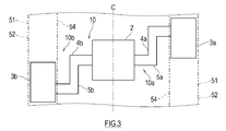
- FIG. 3 is a plan view showing the positional relationship between the evaporator and the two condensers.
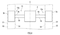
- FIG. 4 is a plan view showing a modification of the positional relationship between the evaporator and the two condensers.
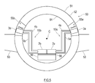
- FIG. 5 is a figure which shows the structure of the loop type heat pipe which concerns on the modification 1. As shown in FIG.
- FIG. 1 is a diagram showing an example of a transportation machine equipped with a loop heat pipe 10 according to an embodiment of the present invention.
- the loop heat pipe 10 is suitable for being mounted on a transportation machine that tilts around the tilt axis C. Examples of such transport aircraft include ships (including submersibles), railway vehicles, automobiles, and aircraft. Below, the aircraft 50 equipped with the loop heat pipe 10 will be described.
- FIG. 1 shows a part of the fuselage 51 and the main wing 53 of the aircraft 50.
- the body 51 has a multi-layer structure including an outer plate 52 and an inner wall 54 provided on the passenger side of the outer plate 52. Cooling chambers 55a and 55b are formed between the outer plate 52 and the inner wall 54.
- the first cooling chamber 55a is formed on the right side of the body 51 in the drawing
- the second cooling chamber 55b is formed on the left side of the body 51 in the drawing.
- the first cooling chamber 55a and the second cooling chamber 55b may be independent or may be communicated with each other.
- the insides of the cooling chambers 55a and 55b have a low temperature due to the cold heat transmitted from the outer plate 52 which is exposed to the outside air (an example of an external fluid) having a temperature significantly lower than that of the ground during flight.
- the outer plate 52 may be provided with an air inlet and an air outlet that communicate with the cooling chambers 55a and 55b, and outside air may be introduced into the cooling chamber 55 during flight.
- the left and right main wings 53 are connected to the sides of the body 51.
- a fuel tank 57 is provided inside each main wing 53.
- the main wing 53 is exposed to the outside air having a temperature significantly lower than that of the ground during flight, and the fuel tank 57 and the fuel stored therein are cooled by the outside air.
- the above-mentioned aircraft 50 is equipped with the loop heat pipe 10 for cooling the heating element 99 provided inside the fuselage 51.
- the heating element 99 is not particularly limited, but examples thereof include electronic devices including heating components such as a control panel, an engine control unit (ECU), and other computers, mechanical components that generate frictional heat such as bearings, and batteries. .. Further, instead of the heating element 99, cabin air may be used as a heat source of the evaporator 2.
- the loop heat pipe 10 has a plurality of circulation flow passages of a first loop 10a and a second loop 10b, and these circulation flow passages are connected to each other by the evaporator 2.
- the first loop 10a is formed by the evaporator 2, the first vapor pipe 4a, the first condenser 3a, and the first liquid pipe 5a.
- the second loop 10b is formed by the evaporator 2, the second vapor pipe 4b, the second condenser 3b, and the second liquid pipe 5b.
- the evaporator 2 is shared by the first loop 10a and the second loop 10b.
- the loop-type heat pipe 10 is degassed from non-condensable gas such as air and then filled with a working fluid.
- the working fluid is not particularly limited, and is a condensable fluid that has been conventionally used as a working fluid for heat pipes (for example, water, alcohol, ammonia, fluorocarbons, hydrofluorocarbons, hydrofluoroethers, and mixtures thereof). May be
- the evaporator 2 includes a heat transfer plate 21 and a housing 22 having a working fluid storage chamber 23 formed therein.
- the heat transfer plate 21 is thermally connected to the heating element 99 via, for example, thermal grease or a heat transfer sheet.
- the working fluid in the working fluid storage chamber 23 absorbs heat from the heating element 99 via the heat transfer plate 21, and a part of it boils and changes to gas. In this way, the two-phase working fluid of the boiling vapor and the liquid moves in the first steam pipe 4a that connects the outlet of the evaporator 2 and the inlet of the first condenser 3a by the pressure difference or the buoyancy to move to the first.
- the second vapor pipe 4b that reaches the condenser 3a and connects the outlet of the evaporator 2 and the inlet of the second condenser 3b is moved by a pressure difference or buoyancy to reach the second condenser 3b. That is, the working fluid storage chamber 23 is in communication with both the first condenser 3a and the second condenser 3b.
- the first condenser 3a is arranged in the first cooling chamber 55a, and the second condenser 3b is arranged in the second cooling chamber 55b.
- a fan 56 for forcibly ventilating the condensers 3a and 3b is provided in the cooling chambers 55a and 55b.
- the first condenser 3a and the second condenser 3b have substantially the same structure.
- a cooling passage (not shown) is formed in the first condenser 3a and the second condenser 3b, and the two-phase working fluid radiates heat while passing through the cooling passage and is cooled and changed to a liquid. ..
- the liquid-phase working fluid descends by gravity into the first liquid pipe 5a that connects the outlet of the first condenser 3a and the inlet of the evaporator 2 and flows back to the evaporator 2.
- the working fluid that has become liquid in the second condenser 3b descends by gravity in the second liquid pipe 5b that connects the outlet of the second condenser 3b and the inlet of the evaporator 2, and returns to the evaporator 2.
- the attitude when the aircraft 50 (an example of a transport aircraft) equipped with the loop heat pipe 10 is installed on a horizontal plane is defined as a “reference attitude”.
- the first condenser 3 a and the second condenser 3 b are located above the evaporator 2. Due to the pressure difference between the heads, the working fluid naturally circulates in the first loop 10a and the second loop 10b.
- the head difference due to the height difference between the evaporator 2 and the condensers 3a and 3b changes, and the driving force for circulating the working fluid changes. To do.
- the first condenser 3a and the second condenser 3b sandwich the tilt axis C (that is, the rotation center of tilt) of the aircraft 50 and the evaporator 2 between them. They are arranged horizontally apart. Further, in the loop type heat pipe 10 in the standard posture, the evaporator 2 is located on a vertical plane passing through the tilt axis C. Furthermore, when the first condenser 3a and the second condenser 3b are viewed parallel to the extending direction of the tilt axis C in the loop-type heat pipe 10 in the reference posture, the first condenser 3a and the second condenser 3b.
- FIG. 3 is a plan view showing the positional relationship between the evaporator 2 and the two condensers 3a and 3b.
- the first condenser 3a and the second condenser 3b are separated from each other in the extending direction of the tilt axis C with the evaporator 2 interposed therebetween. That is, the positions of the first condenser 3a and the second condenser 3b in the front-rear direction of the aircraft 50 are separated with the evaporator 2 interposed therebetween.
- the driving force for circulating the working fluid in one of the first loop 10a and the second loop 10b decreases, but the working fluid in the other loop decreases.
- the driving force to circulate increases. Therefore, since the total circulation amount of the working fluid in the first loop 10a and the second loop 10b is maintained, it is possible to avoid a situation where the heat transport amount is significantly reduced.
- the evaporator 2 and the two condensers 3a and 3b may be provided at the same position in the extending direction of the tilt axis C.
- the loop-type heat pipe 10 is the loop-type heat pipe 10 that is mounted on the transportation machine that tilts about the tilt axis C, and is a liquid-phase working fluid.
- An evaporator 2 for converting at least a part of the gas into a gas
- a first condenser 3a and a second condenser 3b for converting a vapor-phase working fluid into a liquid
- a first communication connecting the evaporator 2 and the first condenser 3a The first vapor pipe 4a and the first liquid pipe 5a are provided
- the second vapor pipe 4b and the second liquid pipe 5b that connect the evaporator 2 and the second condenser 3b are provided.
- the first condenser 3a and the second condenser 3b are located above the evaporator 2 and the first condenser 3a and the second condenser 3b are tilted in a state in which the transportation machine is placed on a horizontal plane. It is separated in the horizontal direction with the axis C and the evaporator 2 interposed therebetween.
- the transport machine includes a heating element 99 and a loop heat pipe 10 including an evaporator 2 that uses the heating element 99 as a heat source to evaporate a working fluid.
- the transport aircraft is an aircraft 50 having an outer plate 52 exposed to an external fluid and an inner wall 54 arranged inside the outer plate 52. At least one of the first condenser 3a and the second condenser 3b is disposed in the cooling chambers 55a and 55b formed between the first condenser 3a and the second condenser 3b.
- the first condenser 3a and the second condenser 3b when the posture of the loop heat pipe 10 changes due to tilting of the transport machine, the first condenser 3a and the second condenser 3b.
- the driving force for flowing the working fluid from one of the two to the evaporator 2 is reduced, but the driving force for flowing the working fluid from the other to the evaporator 2 is maintained. Therefore, even if the posture of the loop heat pipe 10 changes, the circulation amount of the working fluid is maintained, and the heat transportation is continued without the heat transportation amount decreasing.
- the evaporator 2 is positioned on a vertical plane passing through the tilt axis C in a state where the transport machine is placed on a horizontal plane. You can do it.
- the working fluid flowing from the evaporator 2 to the first condenser 3a and the second condenser 3b, or vice versa has a good balance.
- the first condenser 3a and the second condenser 3b are viewed in parallel with the extending direction of the tilt axis C, the first condenser 3a and the second condenser 3b are connected to each other along the tilt axis C. It may be arranged line-symmetrically with respect to a perpendicular line passing through.
- the first condenser 3a and the second condenser 3b sandwich the evaporator 2 and the tilt axis. It may be separated in the stretching direction of C.
- the transport machine has an outer plate 52 exposed to an external fluid, and an inner wall 54 disposed inside the outer plate 52, and a cooling chamber 55a formed between the outer plate 52 and the inner wall 54. At least one of the first condenser 3a and the second condenser 3b may be arranged at 55b.
- the working fluid can be condensed by using the cold heat of the external fluid (outside air).
- the heating element 99 to which the evaporator 2 is thermally connected and the medium radiating heat from the condensers 3a and 3b in an environment where the outside air is significantly lower than room temperature, the heating element 99 to which the evaporator 2 is thermally connected and the medium radiating heat from the condensers 3a and 3b. The temperature difference between and becomes large, and more efficient heat transfer can be performed.
- the transport machine may have a fuel tank 57, and at least one of the first condenser 3a and the second condenser 3b may be arranged in the liquid phase of the fuel tank 57.
- the working fluid can be condensed using the fuel tank 57 having a large heat capacity.
- the fuel tank 57 actively exchanges heat with a low-temperature external fluid, the temperature difference between the heating element 99 to which the evaporator 2 is thermally connected and the medium radiated by the condensers 3a and 3b is reduced. It becomes large and more efficient heat transfer can be performed.
- the two condensers 3a and 3b are connected to the evaporator 2 of the loop heat pipe 10, but the evaporator 2 may be connected to a plurality of condensers of three or more. ..
- the first loop 10a and the second loop 10b of the loop heat pipe 10 are communicated with each other in the evaporator 2, but the first loop 10a and the second loop 10b are respectively It may have an independent circulation channel.
- the loop heat pipe 10 may be configured such that the first loop 10a includes the first evaporator 2a and the second loop 10b includes the second evaporator 2b.
- the first evaporator 2a and the second evaporator 2b are thermally connected to the heating element 99 via a soaking plate 98 made of a material having high thermal conductivity. Good.
- the loop heat pipe 10 of the above embodiment is not limited to the thermosiphon type, but a wick type may be adopted.
- a wick type In the wick type loop heat pipe, in order to recirculate the working fluid from the condenser 3 to the evaporator 2, the capillary force of the working fluid in the wick is used, but gravity is also used. Therefore, even if the present invention is applied to a wick type loop heat pipe, the same effect as described above can be obtained.
Landscapes
- Engineering & Computer Science (AREA)
- General Engineering & Computer Science (AREA)
- Mechanical Engineering (AREA)
- Combustion & Propulsion (AREA)
- Chemical & Material Sciences (AREA)
- Sustainable Development (AREA)
- Life Sciences & Earth Sciences (AREA)
- Physics & Mathematics (AREA)
- Thermal Sciences (AREA)
- Aviation & Aerospace Engineering (AREA)
- Pulmonology (AREA)
- General Health & Medical Sciences (AREA)
- Health & Medical Sciences (AREA)
- Cooling Or The Like Of Electrical Apparatus (AREA)
Abstract
L'invention concerne un caloduc en boucle qui est monté dans un dispositif de transport soumis à une opération d'inclinaison, et qui est équipé : d'un évaporateur pour convertir en gaz au moins une partie d'un fluide de travail en phase liquide ; un premier condenseur et un second condenseur pour convertir en liquide le fluide de travail en phase gazeuse ; un premier tube de vapeur et un premier tube de liquide reliant l'évaporateur et le premier condenseur ; et un second tube de vapeur et un second tube de liquide reliant l'évaporateur et le second condenseur. Dans un état où un dispositif de transport est placé sur une surface horizontale, le premier condenseur et le second condenseur sont positionnés au-dessus de l'évaporateur, et le premier condenseur et le second condenseur sont séparés l'un de l'autre dans la direction horizontale avec un arbre d'inclinaison et l'évaporateur est intercalé entre eux.
Priority Applications (2)
| Application Number | Priority Date | Filing Date | Title |
|---|---|---|---|
| EP19902970.3A EP3904812A4 (fr) | 2018-12-27 | 2019-12-24 | Caloduc en boucle et dispositif de transport |
| US17/418,253 US20220065548A1 (en) | 2018-12-27 | 2019-12-24 | Loop heat pipe and transportation machine |
Applications Claiming Priority (2)
| Application Number | Priority Date | Filing Date | Title |
|---|---|---|---|
| JP2018-245272 | 2018-12-27 | ||
| JP2018245272A JP2020106207A (ja) | 2018-12-27 | 2018-12-27 | ループ型ヒートパイプ及び輸送機 |
Publications (1)
| Publication Number | Publication Date |
|---|---|
| WO2020138079A1 true WO2020138079A1 (fr) | 2020-07-02 |
Family
ID=71127202
Family Applications (1)
| Application Number | Title | Priority Date | Filing Date |
|---|---|---|---|
| PCT/JP2019/050597 Ceased WO2020138079A1 (fr) | 2018-12-27 | 2019-12-24 | Caloduc en boucle et dispositif de transport |
Country Status (4)
| Country | Link |
|---|---|
| US (1) | US20220065548A1 (fr) |
| EP (1) | EP3904812A4 (fr) |
| JP (1) | JP2020106207A (fr) |
| WO (1) | WO2020138079A1 (fr) |
Families Citing this family (2)
| Publication number | Priority date | Publication date | Assignee | Title |
|---|---|---|---|---|
| GB201813420D0 (en) * | 2018-08-17 | 2018-10-03 | Leonardo Mw Ltd | A gas-liquid separator |
| US12098673B2 (en) * | 2022-07-13 | 2024-09-24 | Brian Lee Moffat | Rotary closed-cycle externally-heated engine |
Citations (11)
| Publication number | Priority date | Publication date | Assignee | Title |
|---|---|---|---|---|
| US4254821A (en) * | 1979-08-10 | 1981-03-10 | Thermo Electron Corporation | Heat pipe deicing apparatus |
| JP2001165585A (ja) * | 1999-12-06 | 2001-06-22 | Furukawa Electric Co Ltd:The | 平面型ヒートパイプ |
| JP2003258173A (ja) * | 2002-02-28 | 2003-09-12 | Mitsubishi Electric Corp | 移動体搭載用アンテナ |
| JP2003298270A (ja) * | 2002-03-29 | 2003-10-17 | Mitsubishi Electric Corp | アンテナ装置 |
| JP2004048489A (ja) * | 2002-07-12 | 2004-02-12 | Mitsubishi Electric Corp | 移動体搭載アンテナ及びその冷却装置 |
| CN101566442A (zh) * | 2009-05-31 | 2009-10-28 | 北京奇宏科技研发中心有限公司 | 一种串并联式多蒸发器环路热管 |
| JP2011507165A (ja) * | 2007-12-14 | 2011-03-03 | エアバス オペラツィオンス ゲゼルシャフト ミット ベシュレンクテル ハフツング | 蒸発冷却式燃料電池システム及び蒸発冷却式燃料電池システムの運転方法 |
| JP2012233642A (ja) | 2011-05-02 | 2012-11-29 | Fujitsu Ltd | マルチループ型ヒートパイプ及び電子装置 |
| CN103000595A (zh) * | 2011-09-08 | 2013-03-27 | 北京芯铠电子散热技术有限责任公司 | 一种多向进出相变传热装置及其制作方法 |
| EP2592000A1 (fr) * | 2011-11-08 | 2013-05-15 | Alenia Aermacchi S.p.A. | Réservoir de carburant pour aéronef pourvu d'un système de chauffage à combustible et système de chauffage de carburant pour aéronef équipé d'un tel réservoir |
| US20150068703A1 (en) * | 2013-09-06 | 2015-03-12 | Ge Aviation Systems Llc | Thermal management system and method of assembling the same |
Family Cites Families (6)
| Publication number | Priority date | Publication date | Assignee | Title |
|---|---|---|---|---|
| US5423498A (en) * | 1993-04-27 | 1995-06-13 | E-Systems, Inc. | Modular liquid skin heat exchanger |
| TW331586B (en) * | 1997-08-22 | 1998-05-11 | Biing-Jiun Hwang | Network-type heat pipe device |
| GB2389174B (en) * | 2002-05-01 | 2005-10-26 | Rolls Royce Plc | Cooling systems |
| DE10361653B4 (de) * | 2003-12-30 | 2008-08-07 | Airbus Deutschland Gmbh | Kühleinrichtung zum Abführen von Wärme von einer im Innenraum eines Flugzeuges angeordneten Wärmequelle |
| EP1836449A1 (fr) * | 2005-01-03 | 2007-09-26 | Noise Limit ApS | Systeme de refroidissement a orientations multiples dote d'une pompe a bulles |
| FR3039512B1 (fr) * | 2015-07-28 | 2017-12-22 | Thales Sa | Rechauffage d'un premier equipement aeronautique d'aeronef |
-
2018
- 2018-12-27 JP JP2018245272A patent/JP2020106207A/ja active Pending
-
2019
- 2019-12-24 EP EP19902970.3A patent/EP3904812A4/fr not_active Withdrawn
- 2019-12-24 US US17/418,253 patent/US20220065548A1/en not_active Abandoned
- 2019-12-24 WO PCT/JP2019/050597 patent/WO2020138079A1/fr not_active Ceased
Patent Citations (11)
| Publication number | Priority date | Publication date | Assignee | Title |
|---|---|---|---|---|
| US4254821A (en) * | 1979-08-10 | 1981-03-10 | Thermo Electron Corporation | Heat pipe deicing apparatus |
| JP2001165585A (ja) * | 1999-12-06 | 2001-06-22 | Furukawa Electric Co Ltd:The | 平面型ヒートパイプ |
| JP2003258173A (ja) * | 2002-02-28 | 2003-09-12 | Mitsubishi Electric Corp | 移動体搭載用アンテナ |
| JP2003298270A (ja) * | 2002-03-29 | 2003-10-17 | Mitsubishi Electric Corp | アンテナ装置 |
| JP2004048489A (ja) * | 2002-07-12 | 2004-02-12 | Mitsubishi Electric Corp | 移動体搭載アンテナ及びその冷却装置 |
| JP2011507165A (ja) * | 2007-12-14 | 2011-03-03 | エアバス オペラツィオンス ゲゼルシャフト ミット ベシュレンクテル ハフツング | 蒸発冷却式燃料電池システム及び蒸発冷却式燃料電池システムの運転方法 |
| CN101566442A (zh) * | 2009-05-31 | 2009-10-28 | 北京奇宏科技研发中心有限公司 | 一种串并联式多蒸发器环路热管 |
| JP2012233642A (ja) | 2011-05-02 | 2012-11-29 | Fujitsu Ltd | マルチループ型ヒートパイプ及び電子装置 |
| CN103000595A (zh) * | 2011-09-08 | 2013-03-27 | 北京芯铠电子散热技术有限责任公司 | 一种多向进出相变传热装置及其制作方法 |
| EP2592000A1 (fr) * | 2011-11-08 | 2013-05-15 | Alenia Aermacchi S.p.A. | Réservoir de carburant pour aéronef pourvu d'un système de chauffage à combustible et système de chauffage de carburant pour aéronef équipé d'un tel réservoir |
| US20150068703A1 (en) * | 2013-09-06 | 2015-03-12 | Ge Aviation Systems Llc | Thermal management system and method of assembling the same |
Non-Patent Citations (1)
| Title |
|---|
| See also references of EP3904812A4 |
Also Published As
| Publication number | Publication date |
|---|---|
| EP3904812A1 (fr) | 2021-11-03 |
| JP2020106207A (ja) | 2020-07-09 |
| US20220065548A1 (en) | 2022-03-03 |
| EP3904812A4 (fr) | 2022-09-14 |
Similar Documents
| Publication | Publication Date | Title |
|---|---|---|
| JP6579275B2 (ja) | 機器温調装置 | |
| JP6604330B2 (ja) | 冷媒中継装置、それを用いた冷却装置、および冷却方法 | |
| CN109716051B (zh) | 设备温度调节装置 | |
| JPWO2018047539A1 (ja) | 機器温調装置 | |
| JPH0420788A (ja) | 冷却装置および温度制御装置 | |
| WO2013121772A1 (fr) | Dispositif de refroidissement et système de refroidissement | |
| WO2020138080A1 (fr) | Évaporateur et caloduc de type boucle | |
| WO2018047533A1 (fr) | Appareil de réglage de température de dispositif | |
| WO2020138079A1 (fr) | Caloduc en boucle et dispositif de transport | |
| JP2008171943A (ja) | 電子機器用ラック及びアンプラック | |
| WO2012161002A1 (fr) | Dispositif de refroidissement à plaques plates et son procédé d'utilisation | |
| JP2012255624A (ja) | 電気自動車 | |
| JP2019040730A (ja) | 電池温調装置 | |
| JP2003291900A (ja) | 人工衛星熱制御装置 | |
| US20240206131A1 (en) | Cooling apparatus, system and method of manufacture | |
| JP3539274B2 (ja) | アンテナ装置の冷却構造 | |
| KR101917484B1 (ko) | 배관 구조, 그 배관 구조를 사용한 냉각 장치, 및 냉매 증기 수송 방법 | |
| JPWO2017169969A1 (ja) | 冷却装置 | |
| WO2020129645A1 (fr) | Dispositif de régulation de température d'équipement | |
| JP2018105525A (ja) | 冷却装置およびこれを搭載した電子機器、および電気自動車 | |
| KR102552549B1 (ko) | 냉각 장치 | |
| US20220082335A1 (en) | Loop heat pipe and transportation machine | |
| JP2017041577A (ja) | 冷却装置および冷却方法 | |
| WO2020235475A1 (fr) | Appareil de réglage de température de dispositif | |
| US20240237308A1 (en) | Server with hybrid thermal management system |
Legal Events
| Date | Code | Title | Description |
|---|---|---|---|
| 121 | Ep: the epo has been informed by wipo that ep was designated in this application |
Ref document number: 19902970 Country of ref document: EP Kind code of ref document: A1 |
|
| NENP | Non-entry into the national phase |
Ref country code: DE |
|
| ENP | Entry into the national phase |
Ref document number: 2019902970 Country of ref document: EP Effective date: 20210727 |