WO2020138096A1 - Système de dégazage, procédé de dégazage de liquides, unité de dégazage, module de dégazage, et procédé de fabrication de système de dégazage et procédé de production à partir de ressources naturelles - Google Patents
Système de dégazage, procédé de dégazage de liquides, unité de dégazage, module de dégazage, et procédé de fabrication de système de dégazage et procédé de production à partir de ressources naturelles Download PDFInfo
- Publication number
- WO2020138096A1 WO2020138096A1 PCT/JP2019/050650 JP2019050650W WO2020138096A1 WO 2020138096 A1 WO2020138096 A1 WO 2020138096A1 JP 2019050650 W JP2019050650 W JP 2019050650W WO 2020138096 A1 WO2020138096 A1 WO 2020138096A1
- Authority
- WO
- WIPO (PCT)
- Prior art keywords
- degassing
- liquid
- unit
- hollow fiber
- units
- Prior art date
- Legal status (The legal status is an assumption and is not a legal conclusion. Google has not performed a legal analysis and makes no representation as to the accuracy of the status listed.)
- Ceased
Links
Images





Classifications
-
- B—PERFORMING OPERATIONS; TRANSPORTING
- B01—PHYSICAL OR CHEMICAL PROCESSES OR APPARATUS IN GENERAL
- B01D—SEPARATION
- B01D19/00—Degasification of liquids
- B01D19/0031—Degasification of liquids by filtration
-
- B—PERFORMING OPERATIONS; TRANSPORTING
- B01—PHYSICAL OR CHEMICAL PROCESSES OR APPARATUS IN GENERAL
- B01D—SEPARATION
- B01D63/00—Apparatus in general for separation processes using semi-permeable membranes
- B01D63/02—Hollow fibre modules
- B01D63/021—Manufacturing thereof
- B01D63/0233—Manufacturing thereof forming the bundle
-
- B—PERFORMING OPERATIONS; TRANSPORTING
- B01—PHYSICAL OR CHEMICAL PROCESSES OR APPARATUS IN GENERAL
- B01D—SEPARATION
- B01D63/00—Apparatus in general for separation processes using semi-permeable membranes
- B01D63/02—Hollow fibre modules
- B01D63/04—Hollow fibre modules comprising multiple hollow fibre assemblies
- B01D63/043—Hollow fibre modules comprising multiple hollow fibre assemblies with separate tube sheets
-
- B—PERFORMING OPERATIONS; TRANSPORTING
- B01—PHYSICAL OR CHEMICAL PROCESSES OR APPARATUS IN GENERAL
- B01D—SEPARATION
- B01D65/00—Accessories or auxiliary operations, in general, for separation processes or apparatus using semi-permeable membranes
- B01D65/003—Membrane bonding or sealing
-
- E—FIXED CONSTRUCTIONS
- E21—EARTH OR ROCK DRILLING; MINING
- E21B—EARTH OR ROCK DRILLING; OBTAINING OIL, GAS, WATER, SOLUBLE OR MELTABLE MATERIALS OR A SLURRY OF MINERALS FROM WELLS
- E21B43/00—Methods or apparatus for obtaining oil, gas, water, soluble or meltable materials or a slurry of minerals from wells
- E21B43/34—Arrangements for separating materials produced by the well
- E21B43/40—Separation associated with re-injection of separated materials
-
- B—PERFORMING OPERATIONS; TRANSPORTING
- B01—PHYSICAL OR CHEMICAL PROCESSES OR APPARATUS IN GENERAL
- B01D—SEPARATION
- B01D2313/00—Details relating to membrane modules or apparatus
- B01D2313/10—Specific supply elements
-
- B—PERFORMING OPERATIONS; TRANSPORTING
- B01—PHYSICAL OR CHEMICAL PROCESSES OR APPARATUS IN GENERAL
- B01D—SEPARATION
- B01D2313/00—Details relating to membrane modules or apparatus
- B01D2313/12—Specific discharge elements
Definitions
- One aspect of the present invention is a deaeration system in which a plurality of deaeration units are accommodated in parallel in a housing, a liquid deaeration method using the deaeration system, a deaeration unit used in the deaeration system,
- the present invention relates to a degassing module used in this degassing system, a method for manufacturing this degassing system, and a method for producing natural resources.
- a degassing unit that degasses a liquid using a hollow fiber membrane is known.
- a deaeration system in which a plurality of deaeration units are housed in a housing in order to cope with an increase in size or an increase in flow rate (for example, see Patent Document 1).
- an aspect of the present invention is to use a degassing system capable of reducing the deviation of the flow rates of liquids flowing through a plurality of degassing units, a liquid degassing method using the degassing system, and a degassing system used in the degassing system. It is an object of the present invention to provide a degassing unit, a degassing module used in the degassing system, a method for manufacturing the degassing system, and a method for producing a natural resource.
- a degassing system includes a plurality of degassing units for degassing a liquid, and a cylindrical housing that houses the plurality of degassing units in parallel.
- Each includes a hollow fiber membrane bundle in which a plurality of hollow fiber membranes are bundled in a cylindrical shape, and a tubular body that houses the hollow fiber membrane bundle, and the housing has an inlet to which liquid is supplied from the outside.
- the degassing unit is configured so that the pressure loss of the liquid varies depending on the distance from the central axis of the housing.
- the degassing system multiple degassing units are housed in parallel in a cylindrical housing.
- the pressure loss of the liquid flowing through the plurality of degassing units is the same, the flow rate of the liquid flowing through the degassing unit differs depending on the distance from the central axis of the housing.
- the plurality of degassing units are configured so that the pressure loss of the liquid varies depending on the distance from the central axis of the housing. This difference in pressure loss serves to offset the above difference in flow rate. Accordingly, it is possible to reduce the deviation in the flow rate of the liquid flowing through the plurality of degassing units. As a result, for example, the degassing performance of the entire degassing system can be improved.
- a suction tube that communicates with the inside of the hollow fiber membrane and penetrates the housing may be further provided.
- the suction pipe by providing the suction pipe, the liquid can be appropriately degassed in the degassing unit, and the degassed gas can be appropriately discharged to the outside of the housing.
- the degassing unit that overlaps the inlet when viewed from the direction along the central axis has a larger liquid pressure loss than the degassing unit that does not overlap the inlet when viewed from the direction along the central axis. May be configured.
- the degassing unit that overlaps with the inlet when viewed from the direction along the central axis receives the liquid supply pressure from the inlet more strongly than the degassing unit that does not overlap with the inlet when viewed from the direction along the central axis, making it easier for the liquid to flow. Become.
- the degassing unit that overlaps the inlet when viewed from the direction along the central axis is configured so that the pressure loss of the liquid becomes larger than the degassing unit that does not overlap the inlet when viewed from the direction along the central axis. Therefore, this difference in pressure loss acts to cancel out the difference in liquid supply pressure. As a result, it is possible to reduce the deviation in the flow rate of the liquid flowing through these degassing units.
- the region from the inner peripheral surface of the housing to the position corresponding to 0.7 times the outer diameter of the degassing unit on the central axis side is defined as the outer region, and the region inside the outer region is defined as the inner region.
- the plurality of degassing units in the inner region, have an inner degassing unit and an outer degassing unit that is farther from the central axis than the inner degassing unit, and the inner degassing unit is the outer degassing unit.
- the pressure loss of the liquid may be larger than that.
- the pressure loss of the liquid flowing through the plurality of degassing units When the pressure loss of the liquid flowing through the plurality of degassing units is the same, the flow rate of the liquid flowing through the degassing units tends to decrease in the inner region as the distance from the central axis of the housing increases.
- the pressure loss of the liquid in the inner degassing unit is larger than that in the outer degassing unit, and thus the difference in pressure loss serves to cancel the difference in flow rate. As a result, it is possible to reduce the deviation in the flow rate of the liquid flowing through the inner degassing unit and the outer degassing unit.
- the area from the inner peripheral surface of the housing to the position corresponding to 0.7 times the outer diameter of the degassing unit on the central axis side is defined as the outer area
- the area inside the outer area is defined as the inner area.
- the area from the inner peripheral surface of the housing to the center axis side up to a position corresponding to 0.7 times the outer diameter of the degassing unit is the outer area, and the area inside the outer area is the inner area.
- the degassing unit located in the inner area has a larger pressure loss of liquid as it moves away from the central axis. It may be configured to be.
- the deaeration unit arranged in the inner region is separated from the central axis. Since the pressure loss of the liquid increases as the distance increases, the deviation of the flow rate of the liquid flowing through the degassing unit can be appropriately reduced in the inner region.
- the degassing unit arranged in the outer region may be configured such that the pressure loss of the liquid is larger than that of the degassing unit closest to the outermost region among the degassing units arranged in the inner region. Good.
- the degassing unit arranged in the outer region is configured so that the pressure loss of the liquid is larger than that of the degassing unit arranged in the inner region that is closest to the outermost region. Therefore, the difference in the flow rate of the liquid can be appropriately reduced even between the degassing unit arranged in the inner region and the degassing unit arranged in the outer region.
- the degassing unit is formed by connecting a plurality of degassing modules, and each of the plurality of degassing modules has a plurality of hollow fiber membranes arranged around a liquid supply path to which a liquid is supplied.
- a liquid degassing method is the degassing system according to any one of the above, wherein liquid is supplied from the inlet to the plurality of degassing units and a plurality of hollows of the plurality of degassing units are provided. The liquid is degassed by depressurizing the inside of the thread film.
- a degassing unit is a degassing unit used in any of the above degassing systems, a hollow fiber membrane bundle in which a plurality of hollow fiber membranes are bundled in a cylindrical shape, and a hollow And a tubular body accommodating the thread film bundle.
- a degassing module is a degassing module used in the above degassing system, which is a hollow structure having a plurality of hollow fiber membranes arranged around a liquid supply path to which a liquid is supplied.
- the fiber membrane bundle includes a hollow fiber membrane bundle, and a tubular body having a discharge port for discharging the liquid.
- a method for manufacturing a degassing system includes a plurality of degassing units, an inlet that accommodates the plurality of degassing units, a liquid is supplied from the outside, and an outlet that discharges the liquid to the outside. And a suction pipe, and a plurality of sealing units that divide the internal space of the housing into an upstream region on the inlet side and a downstream region on the outlet side via a plurality of degassing units are provided.
- the deaeration unit is fixed to the housing, and the pressure loss of the liquid in the plurality of deaeration units is changed according to the distance from the central axis of the housing.
- a hollow fiber membrane bundle having a plurality of hollow fiber membranes arranged around the liquid supply passage to which the liquid is supplied, and a discharge port for accommodating the hollow fiber membrane bundle and discharging the liquid are formed.
- a plurality of degassing modules each having a cylindrical body and a connecting supply pipe having a plurality of openings for allowing liquid to pass therethrough, and inserting the connecting supply pipe into the liquid supply passages of the plurality of degassing modules. Then, the liquid supply paths of the plurality of degassing modules are connected in series by the connection supply pipes, and the plurality of openings are formed so that the liquid is supplied in parallel to the hollow fiber membrane bundles of the plurality of degassing modules.
- the degassing unit may be manufactured by arranging it at a position corresponding to the degassing module.
- the liquid is supplied from the inlet to the plurality of degassing units, and a plurality of hollows of each of the plurality of degassing units are provided.
- a degassing step of degassing the liquid by depressurizing the inside of the thread film and a press-fitting step of press-fitting the liquid degassed in the degassing step into a natural resource mining site are provided.
- a degassing system capable of reducing the deviation of the flow rate of liquid flowing through a plurality of degassing units.
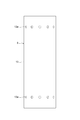
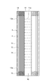
- FIG. 2 is a schematic sectional view taken along line II-II shown in FIG. 1. It is a schematic sectional drawing of the deaeration system for demonstrating an example of a deaeration unit. It is a schematic sectional drawing of the deaeration system for demonstrating an example of a deaeration unit.
- FIG. 5 is a schematic sectional view taken along line VV shown in FIG. 3 or FIG. 4. It is a schematic front view of a deaeration unit. It is a schematic sectional drawing of a deaeration unit. It is a schematic sectional drawing of the edge part of a hollow fiber membrane bundle.
- the degassing system of this embodiment is a system for degassing a liquid.
- the liquid that is degassed by the degassing system include water.
- the degassing system 1 of the present embodiment includes a plurality of degassing units 2, a housing 3 that houses the degassing units 2, and a suction pipe 4 (see FIGS. 3 to 5 ). ), and.
- the deaeration unit 2 may be configured by connecting a plurality of deaeration modules 5 like the deaeration unit 2A shown in FIG. 3, and one deaeration unit 2B like the deaeration unit 2B shown in FIG.
- the air module 5 may be used.
- the degassing unit 2A shown in FIG. 3 and the degassing unit 2B shown in FIG. 4 are examples of the degassing unit 2.
- FIG. 3 and FIG. 4 only one deaeration unit 2 among the plurality of deaeration units 2 is illustrated and the remaining deaeration units 2 are not illustrated in order to make the drawings easy to see.
- the degassing module 5 includes, for example, a module inner tube 11, a hollow fiber membrane bundle 12, and a module container (cylindrical body) 13.
- the module inner pipe 11 is a pipe forming the liquid supply passage 10 to which a liquid such as water is supplied on the inner peripheral side.
- the module inner tube 11 is formed, for example, in a linear tube shape that extends linearly.
- the module inner tube 11 is formed with a plurality of inner tube openings 11a.
- the inner pipe opening 11a is for passing the liquid supplied to the liquid supply passage 10 of the module inner pipe 11.
- the number, position, size, etc. of the inner tube openings 11a are not particularly limited.
- the hollow fiber membrane bundle 12 has a plurality of hollow fiber membranes 14 arranged around the module inner tube 11. Therefore, the liquid supply passage 10 is arranged on the inner peripheral side of the hollow fiber membrane bundle 12.
- the hollow fiber membrane bundle 12 is configured by bundling a plurality of hollow fiber membranes 14 into a tubular shape such as a cylindrical shape.
- the hollow fiber membrane 14 is a hollow fiber membrane that allows gas to pass through but does not allow liquid to pass through.
- the hollow fiber membrane bundle 12 degasses the liquid flowing out from the inner tube opening 11 a of the module inner tube 11 by depressurizing the inside of the hollow fiber membrane 14.
- the material, shape, shape, etc. of the hollow fiber membrane 14 are not particularly limited.
- Examples of the material of the hollow fiber membrane 14 include polyolefin resins such as polypropylene and poly(4-methylpentene-1), silicone resins such as polydimethylsiloxane copolymers thereof, and fluorine resins such as PTFE and vinylidene fluoride. Resins.
- Examples of the membrane shape (sidewall shape) of the hollow fiber membrane 14 include a porous membrane, a microporous membrane, and a non-porous homogeneous membrane (non-porous membrane).
- Examples of the membrane form of the hollow fiber membrane 14 include a symmetrical membrane (homogeneous membrane) in which the entire membrane has a uniform chemical or physical structure, or an asymmetric membrane (heterogeneous membrane) in which the chemical or physical structure of the membrane differs depending on the membrane portion.
- An asymmetric membrane is a membrane having a non-porous dense layer and a porous layer. In this case, the dense layer may be formed anywhere in the film, such as the surface layer of the film or the inside of the porous film.
- the heterogeneous film also includes a composite film having different chemical structures and a multi-layer structure film such as a three-layer structure.
- the hollow fiber membrane bundle 12 can be formed of, for example, a woven fabric (not shown) in which a plurality of hollow fiber membranes 14 which are wefts are woven with warp threads.
- This woven fabric is also referred to as a hollow fiber membrane sheet, and a plurality of hollow fiber membranes 14 are woven like a blind.
- This woven fabric is composed of, for example, 30 to 90 hollow fiber membranes 14 per inch. Then, this woven fabric is wound around the module inner tube 11 (around the liquid supply path) so that the plurality of hollow fiber membranes 14 extend in the axial direction of the module inner tube 11 (the liquid supply path 10), thereby forming a cylindrical shape.
- the hollow fiber membrane bundle 12 can be constructed.
- the module container 13 is a container for housing the hollow fiber membrane bundle 12. A region between the module inner tube 11 and the module container 13 becomes a degassing region A for degassing the liquid by the hollow fiber membrane bundle 12.
- the module container 13 is formed, for example, in a cylindrical shape extending in the axial direction of the module inner tube 11 (liquid supply passage 10), and both ends thereof are open.
- the module container 13 is formed with a plurality of outlets 13a.
- the discharge port 13a is for discharging the liquid that has passed through the hollow fiber membrane bundle 12 in the degassing region A from the module container 13 (the degassing module 5).
- the number, position, size, etc. of the discharge ports 13a are not particularly limited.
- both ends 12 a of the hollow fiber membrane bundle 12 are fixed to the module inner tube 11 and the module container 13 by the sealing portion 15.
- the sealing portion 15 is made of resin, for example.
- the resin used for the sealing portion 15 include epoxy resin, urethane resin, ultraviolet curable resin, and polyolefin resin such as polyethylene and polypropylene.
- the sealing portion 15 is filled in the entire region between the inner tube 11 of the module and the module container 13 except the inside of the hollow fiber membrane 14. That is, the sealing portion 15 is filled between the hollow fiber membranes 14, between the hollow fiber membrane bundle 12 and the module inner tube 11, and between the hollow fiber membranes 14 and the module container 13. Is not filled inside. Therefore, the inside of the hollow fiber membrane 14 is open to both ends of the degassing module 5 from the sealing portion 15, and the inside of the hollow fiber membrane 14 can be sucked from both ends of the degassing module 5. Has become. That is, the openings at both ends of the module container 13 are intake openings that open or expose the inside of the hollow fiber membrane 14 so that the inside of the hollow fiber membrane 14 can be sucked and decompressed.
- the degassing unit 2A configured by connecting a plurality of degassing modules 5 has, for example, a connection supply pipe that connects the liquid supply paths 10 of the plurality of degassing modules 5 in series.
- the connection supply pipe 6A is one long pipe connected to the plurality of degassing modules 5, and the liquid supply passages 10 of the plurality of degassing modules 5 are formed on the inner peripheral side thereof. Therefore, the plurality of degassing modules 5 are connected in series by the connection supply pipe 6A in appearance.
- the number of the deaeration modules 5 constituting the deaeration unit 2A is not particularly limited, but in the following description, as an example, four deaeration modules 5 are connected.
- the four degassing modules 5 are referred to as a degassing module 5A, a degassing module 5B, a degassing module 5C, and a degassing module 5D in the order of the liquid flow direction in the connection supply pipe 6A.
- the degassing module 5A is the degassing module 5 arranged on the most upstream side
- the degassing module 5D is the degassing module 5 arranged on the most downstream side.
- the degassing unit 2A is vertically installed, for example, in the connection supply pipe 6A so that the liquid flows upward from below.
- the degassing module 5A arranged on the most upstream side is arranged on the lowermost side
- the degassing module 5D arranged on the most downstream side is arranged on the uppermost side.
- a supply port 6a for supplying the liquid to the connection supply pipe 6A is formed at the upstream end of the connection supply pipe 6A.
- the downstream end of the connection supply pipe 6A is sealed.
- the inner peripheral side of the connection supply pipe 6A forming the liquid supply paths 10 of the plurality of degassing modules 5 penetrates from the upstream side to the downstream side. For this reason, a member serving as a resistance to the flow of the liquid may be arranged on the inner peripheral side of the connection supply pipe 6A (the module inner pipe 11 of each degassing module 5), but the connection supply pipe 6A is sealed. There is no member arranged to block the flow of liquid. Then, the liquid supplied from the supply port 6a is serially supplied to the liquid supply passages 10 of the plurality of degassing modules 5 by the connection supply pipe 6A.
- connection supply pipe 6A an opening 6b through which the liquid passes is formed at a position corresponding to the plurality of degassing modules 5 so that the liquid is supplied in parallel to the hollow fiber membrane bundles 12 of the plurality of degassing modules 5. ing. Therefore, the liquid supplied to the supply port 6a of the connection supply pipe 6A is supplied to the degassing area A of each degassing module 5 through the opening 6b formed at the position corresponding to each degassing module 5 ( Flow out). As a result, the liquid is supplied in parallel to the hollow fiber membrane bundles 12 of the plurality of degassing modules 5.
- the respective degassing modules 5 and the connection supply pipe 6A may be in close contact with each other or may be separated from each other.
- the inner tube opening 11a of each deaeration module 5 and the opening 6b of the connection supply pipe 6A are formed at a position where they at least partially overlap each other.
- the liquid can be supplied to the degassing region A of each degassing module 5 from the connection supply pipe 6A.
- the degassing unit 2B configured by one degassing module 5 is inserted into, for example, the module inner tube 11 of the degassing module 5, and the degassing module is provided on the inner peripheral side thereof. It has a connection supply pipe 6B forming the liquid supply passage 10 of 5.
- a supply port 6a for supplying the liquid to the connection supply pipe 6B is formed at the upstream end of the connection supply pipe 6B.
- the downstream end of the connection supply pipe 6B is sealed.
- the inner peripheral side of the connection supply pipe 6B forming the liquid supply passage 10 of the degassing module 5 penetrates from the upstream side to the downstream side. Therefore, a member that serves as a resistance to the flow of the liquid may be arranged on the inner peripheral side of the connection supply pipe 6B (the module inner pipe 11 of the degassing module 5), but the connection supply pipe 6B is sealed. No member is arranged to block the flow of liquid. Then, the liquid supplied from the supply port 6a is supplied to the liquid supply passage 10 of the degassing module 5 by the connection supply pipe 6B.
- connection supply pipe 6B is formed with an opening 6b through which the liquid passes so that the liquid is supplied to the hollow fiber membrane bundle 12 of the degassing module 5. Therefore, the liquid supplied to the supply port 6a of the connection supply pipe 6B is supplied (flows out) to the degassing region A of the degassing module 5 through the opening 6b. As a result, the liquid is supplied to the hollow fiber membrane bundle 12 of the degassing module 5.
- the degassing module 5 and the connection supply pipe 6B may be in close contact with each other or may be separated from each other.
- the inner pipe opening 11a of the deaeration module 5 and the opening 6b of the connection supply pipe 6B are formed at positions at least partially overlapping with each other.
- the liquid can be supplied to the degassing region A of the degassing module 5 from the connection supply pipe 6B.
- a flow path for the liquid to flow is formed in the space therebetween, so that the inner tube opening 11a of the degassing module 5 and the connection supply pipe 6B are formed.
- the liquid can be supplied to the degassing region A of the degassing module 5 from the connection supply pipe 6B regardless of the positional relationship with the opening 6b.
- connection supply pipe 6A and the connection supply pipe 6B are collectively referred to as the connection supply pipe 6 unless otherwise specified.
- the connection supply pipe 6B may not be provided, and the module inner pipe 11 may double as the connection supply pipe 6B.
- a supply port for supplying the liquid to the module inner tube 11 is formed at the upstream end of the module inner tube 11, and the downstream end of the module inner tube 11 is sealed.
- the housing 3 is formed in a cylindrical shape.
- the housing 3 accommodates the plurality of deaeration units 2 in parallel so that the plurality of deaeration units 2 are arranged in parallel with the central axis L of the housing 3.
- the inlet 3a is formed at the lower end of the housing 3, for example.
- the inlet 3a communicates with the supply port 6a of each degassing unit 2. Therefore, the liquid supplied from the inlet 3 a is supplied to the liquid supply passage 10 of each degassing unit 2 from the supply port 6 a of each degassing unit 2.
- the outlet 3b is formed at the upper end of the housing 3, for example.
- the outlet 3b is in communication with the outlet 13a of each degassing unit 2. Therefore, the liquid discharged from the discharge port 13a of each degassing unit 2 is discharged from the outlet 3b of the housing 3.
- the housing 3 is provided with a housing sealing portion (sealing portion) 7 and a degassing unit support portion 8.
- the housing sealing portion 7 fixes the upstream end (lower end) of the connection supply pipe 6 (connection supply pipe 6A or connection supply pipe 6B) to the inner peripheral surface of the housing 3. Further, the casing sealing unit 7 partitions the internal space of the casing 3 into an upstream region B on the inlet 3a side and a downstream region C on the outlet 3b side via the plurality of deaeration units 2.
- a metal such as stainless steel, a fiber reinforced resin (FRP), or a resin in which a metal such as iron is lined is used.
- the casing sealing portion 7 is filled in the entire area between the joint supply pipe 6 and the casing 3 except the inside of the joint supply pipe 6. That is, the housing sealing portion 7 is filled between the connection supply pipe 6 and the housing 3, but not inside the connection supply pipe 6. Therefore, the inside of the connection supply pipe 6 is open to the upstream region B from the supply port 6a.
- the liquid supplied from the inlet 3a to the upstream region B is supplied to the inside of the connection supply pipe 6 only from the supply port 6a, and further, the degassing region A of the degassing module 5 is supplied from the opening 6b and the inner pipe opening 11a. Is supplied to.
- the casing sealing portion 7 is arranged on the upstream side of all the discharge ports 13a in the flow direction of the liquid flowing through the connection supply pipe 6. Therefore, the inside of the module container 13 is open to the downstream region C from the discharge port 13a. Then, the liquid supplied to the degassing region A through the opening 6b and the inner pipe opening 11a is discharged to the downstream region C only through the discharge port 13a, and further discharged from the housing 3 through the outlet 3b.
- the degassing unit support 8 is fixed to the downstream end (upper end) of the degassing unit 2 and the housing 3 to support the downstream end of the degassing unit 2.
- the degassing unit support portion 8 is formed, for example, in a rod shape extending from the degassing unit 2 to the housing 3, and does not seal between the degassing unit 2 and the housing 3. Therefore, the liquid discharged from the discharge port 13a to the downstream region C is discharged from the outlet 3b to the outside of the housing 3 without being blocked by the degassing unit support portion 8.
- the inner diameter of the housing 3 is not particularly limited, but is preferably 400 mm or more and 1800 mm or less, more preferably 600 mm or more and 1650 mm or less, and further preferably 470 mm or more and 800 mm or less.
- the diameter of the degassing unit 2 is not particularly limited, but is preferably 114 mm or more and 318 mm or less, more preferably 125 mm or more and 216 mm or less, and further preferably 160 mm or more and 170 mm or less.
- the diameter of the degassing unit 2 refers to the diameter of the module container 13.
- the number of the deaeration units 2 housed in the housing 3 is not particularly limited, but from the viewpoint of increasing the flow rate while ensuring the installability of the deaeration system 1, for example, 50 or more and 200 or less. Is preferable, 76 to 180 are more preferable, and 150 to 160 are more preferable.
- the flow rate of the liquid supplied to the housing 3 is not particularly limited, but from the viewpoint of improving the degassing efficiency of the degassing unit 2, for example, it is preferably 150 m 3 /h or more and 1200 m 3 /h or less, and 200 m 3 /h or more. It is more preferably 1000 m 3 /h or less, further preferably 450 m 3 /h or more and 960 m 3 /h or less.
- the ideal residence time of the liquid in the housing 3 is not particularly limited, but from the viewpoint of increasing the flow rate while suppressing the housing 3 from becoming too large, for example, 7 seconds or more and 35 seconds or less are preferable, 17 seconds or more and 28 seconds or less are more preferable, and 20 seconds or more and 22 seconds or less are still more preferable.
- the ideal residence time of the liquid in the housing 3 is a value (V/Q) obtained by dividing the volume Vm 3 of the housing 3 by the flow rate Qm 3 /h of the liquid.
- the ideal residence time of the liquid in the upstream region B is not particularly limited, but from the viewpoint of appropriately supplying the liquid to each degassing unit 2 while suppressing the degassing system 1 from becoming too large, for example, 3 seconds or more. It is preferably 12 seconds or less, more preferably 4 seconds or more and 8 seconds or less, still more preferably 5 seconds or more and 6 seconds or less.
- the ideal residence time of the liquid in the upstream region B means a value (V/Q) obtained by dividing the volume Vm 3 of the upstream region B by the flow rate Qm 3 /h of the liquid.
- the suction pipe 4 communicates with the inside of the hollow fiber membrane 14 in order to suck (vacuum) the inside of the hollow fiber membrane 14.
- the suction tube 4 extends through the housing 3 to the outside of the housing 3 so as to be sucked by a suction pump such as a vacuum pump provided outside the housing 3.
- a suction pump such as a vacuum pump provided outside the housing 3.
- the inside of the hollow fiber membrane 14 is opened from the sealing portion 15 to both ends of the degassing module 5. Therefore, the suction pipe 4 is connected to both ends of the degassing module 5 whose inside of the hollow fiber membrane 14 is open.
- sucking the suction tube 4 the inside of the hollow fiber membrane 14 can be sucked from both ends of the degassing module 5.
- the degassing modules 5 since the plurality of degassing modules 5 are connected in series by the connection supply pipe 6 in appearance, the degassing modules 5 adjacent to each other along the connection supply pipe 6 are provided. In between, the end faces of the other side are arranged so as to face each other. Therefore, one suction pipe 4 may be connected to the facing end surface.
- the suction pipe 4 may be provided in each of the plurality of degassing units 2, or may be provided in each of the plurality of degassing units 2. Further, when one deaeration unit 2 is composed of a plurality of deaeration modules 5 like the deaeration unit 2A shown in FIG. 3, the suction pipe 4 is connected to each of the plurality of deaeration modules 5. Alternatively, one suction tube 4 may be connected to the plurality of degassing modules 5. Further, in the degassing unit 2A shown in FIG. 3, since the plurality of degassing modules 5 are connected in series by the connection supply pipe 6 in appearance, the degassing modules 5 adjacent to each other along the connection supply pipe 6 are provided. In between, the end faces of the other side are arranged so as to face each other. Therefore, one suction pipe 4 may be connected to the facing end surface.
- a liquid such as water is supplied from the inlet 3a of the housing 3 to the upstream area B of the housing 3. Then, the liquid supplied to the upstream region B is supplied to the connection supply pipe 6 from the supply port 6a, passes through the opening 6b of the connection supply pipe 6 and the inner pipe opening 11a of the degassing module 5, and then the degassing module 5 Is supplied to the degassing area A of Thereby, the liquid is supplied to the hollow fiber membrane bundle 12 of the degassing module 5. In the degassing region A, the liquid supplied from the inner tube opening 11a passes between the plurality of hollow fiber membranes 14 in the hollow fiber membrane bundle 12 and is then discharged from the discharge port 13a.
- the suction pipe 4 is sucked to reduce the pressure inside the plurality of hollow fiber membranes 14, whereby the dissolved gas, bubbles, etc. of the liquid passing between the plurality of hollow fiber membranes 14 are degassed. Then, the degassed liquid is discharged from the discharge port 13a to the downstream region C, and further discharged from the outlet 3b to the outside of the housing 3.
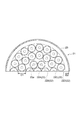
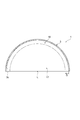
- FIG. 9 shows only half of the degassing unit 22.
- Each degassing unit 22 is configured by connecting four degassing modules like the degassing unit 2A shown in FIG. 3, and all the degassing units 22 are the same.
- a plurality of degassing units 22 are arranged in four rows from the central axis of the housing 23 toward the inner peripheral surface side of the housing 23.
- the deaeration unit 22 arranged closest to the center is the deaeration unit 22A in the first row.
- the deaeration unit 22 arranged on the outer peripheral side of the deaeration unit 22A in the first row was referred to as a deaeration unit 22B in the second row.
- the deaeration unit 22 arranged on the outer peripheral side of the deaeration unit 22B in the second row was referred to as a deaeration unit 22C in the third row.
- the deaeration unit 22 arranged on the outer peripheral side of the deaeration unit 22C in the third row and the outermost peripheral side was referred to as a deaeration unit 22D in the fourth row.
- the deaeration unit 22A in the first row is composed of one deaeration unit 22 arranged on the central axis of the housing 23.
- the deaeration unit 22B in the second row is composed of six deaeration units 22 so as to surround the deaeration unit 22A in the first row.
- the deaeration unit 22C in the third row is composed of 13 deaeration units 22 so as to surround the deaeration unit 22B in the second row.
- the deaeration unit 22D in the fourth row is composed of 19 deaeration units 22 so as to surround the deaeration unit 22C in the third row.
- the analysis software includes ANSYS Fleunt Ver. 19.0 was used.
- the liquid has a density of 1025.5 kg/m 3 and a viscosity of 0.001164 Pa ⁇ s, using seawater as a model.
- the pressure coefficient of the hollow fiber membrane bundle was set to 1.9 ⁇ 10 10 from the analysis value of one degassing module, using a porous model (flow path having pressure resistance) as a model.
- EF-040P manufactured by DIC Corporation was used in the analysis for obtaining the pressure coefficient.
- the inner diameter of the housing 23 is 1645 mm
- the outer diameter D1 of the degassing unit 22 is 163 mm
- a plurality of degassing units 22 are connected to the housing.
- the distance D2 to the inner peripheral surface of 23 was 200 mm.
- the distance D2 from the plurality of deaeration units 22 to the inner peripheral surface of the housing 23 is the shortest distance from the circumscribed circle of the plurality of deaeration units 22 to the inner peripheral surface of the housing 23.
- the distance D2 is about 1.23 times the outer diameter D1 of the degassing unit 22.
- the ratio (D2/D1) of the distance D2 to the outer diameter D1 of the degassing unit 22 is about 1.23.
- the diameter of the inlet 3a of the housing 23 is set to 350 mm, and when viewed from the direction along the central axis of the housing 23, all the deaeration units 22A in the first row overlap the inlet 3a, and the deaeration unit in the second row. Part of 22B overlaps with the inlet 3a, and the deaeration unit 22C in the third row and the deaeration unit 22D in the fourth row do not overlap with the inlet 3a at all.
- the total flow rate of the liquid supplied to the degassing system 21 was 663 m 3 /h, and the ideal residence time of the liquid in the upstream region B (see FIG. 1) of the housing 23 was 5.1 seconds.
- the inner diameter of the housing 23 is 1607 mm
- the outer diameter D1 of the degassing unit 22 is 163 mm
- the housings are separated from the plurality of degassing units 22.
- the distance D2 to the inner peripheral surface of 23 was 182 mm.
- the distance D2 is about 1.12 times the outer diameter D1 of the degassing unit 22.
- the ratio (D2/D1) of the distance D2 to the outer diameter D1 of the degassing unit 22 is about 1.12.
- the diameter of the inlet 3a of the housing 23 is set to 350 mm, and when viewed from the direction along the central axis of the housing 23, all the deaeration units 22A in the first row overlap the inlet 3a, and the deaeration unit in the second row. Part of 22B overlaps with the inlet 3a, and the deaeration unit 22C in the third row and the deaeration unit 22D in the fourth row do not overlap with the inlet 3a at all.
- the total flow rate of the liquid supplied to the degassing system 21 was set to 663 m 3 /h, and the ideal residence time of the liquid in the upstream region B of the housing 23 was set to 4.7 seconds.
- the inner diameter of the housing 23 is 1405 mm
- the outer diameter D1 of the degassing unit 22 is 163 mm
- the plurality of degassing units 22 are connected to the housing.
- the distance D2 to the inner peripheral surface of 23 was 81 mm.
- the distance D2 is about 0.50 times the outer diameter D1 of the degassing unit 22.
- the ratio (D2/D1) of the distance D2 to the outer diameter D1 of the degassing unit 22 is about 0.50.
- the diameter of the inlet 3a of the housing 23 is set to 350 mm, and when viewed from the direction along the central axis of the housing 23, all the deaeration units 22A in the first row overlap the inlet 3a, and the deaeration unit in the second row. Part of 22B overlaps with the inlet 3a, and the deaeration unit 22C in the third row and the deaeration unit 22D in the fourth row do not overlap with the inlet 3a at all. Further, the total flow rate of the liquid supplied to the degassing system 21 was set to 663 m 3 /h, and the ideal residence time of the liquid in the upstream region B of the housing 23 was set to 3.7 seconds.
- the inner diameter of the housing 23 is 1270 mm
- the outer diameter D1 of the degassing unit 22 is 163 mm
- the housings are separated from the plurality of degassing units 22.
- the distance D2 to the inner peripheral surface of 23 was set to 28.5 mm.
- the distance D2 is about 0.17 times the outer diameter D1 of the degassing unit 22.
- the ratio (D2/D1) of the distance D2 to the outer diameter D1 of the degassing unit 22 is about 0.17.
- the diameter of the inlet 3a of the housing 23 is 350 mm, and when viewed from the direction along the central axis of the housing 23, all of the deaeration unit 22A in the first row overlaps the inlet 3a, and the deaeration unit in the second row. Part of 22B overlaps with the inlet 3a, and the deaeration unit 22C in the third row and the deaeration unit 22D in the fourth row do not overlap with the inlet 3a at all. Further, the total flow rate of the liquid supplied to the degassing system 21 was set to 663 m 3 /h, and the ideal residence time of the liquid in the upstream region B of the housing 23 was set to 3.0 seconds.
- the inner diameter of the housing 23 is 1645 mm
- the outer diameter D1 of the degassing unit 22 is 163 mm
- the plurality of degassing units 22 are connected to the housing.
- the distance D2 to the inner peripheral surface of 23 was 200 mm.
- the distance D2 is about 1.23 times the outer diameter D1 of the degassing unit 22.
- the ratio (D2/D1) of the distance D2 to the outer diameter D1 of the degassing unit 22 is about 1.23.
- the diameter of the inlet 3a of the housing 23 is 420 mm, and when viewed from the direction along the central axis of the housing 23, all of the deaeration unit 22A in the first row and the deaeration unit 22B in the second row are the inlet 3a.
- the deaeration unit 22C in the third row and the deaeration unit 22D in the fourth row do not overlap with the inlet 3a at all.
- the total flow rate of the liquid supplied to the degassing system 21 was set to 663 m 3 /h, and the ideal residence time of the liquid in the upstream region B of the housing 23 was set to 5.1 seconds.
- the housing 23 has an inner diameter of 1645 mm
- the degassing unit 22 has an outer diameter D1 of 163 mm
- a plurality of degassing units 22 are connected to the housing.
- the distance D2 to the inner peripheral surface of 23 was 200 mm.
- the distance D2 is about 1.23 times the outer diameter D1 of the degassing unit 22.
- the ratio (D2/D1) of the distance D2 to the outer diameter D1 of the degassing unit 22 is about 1.23.
- the diameter of the inlet 3a of the housing 23 is set to 350 mm, and when viewed from the direction along the central axis of the housing 23, all the deaeration units 22A in the first row overlap the inlet 3a, and the deaeration unit in the second row. Part of 22B overlaps with the inlet 3a, and the deaeration unit 22C in the third row and the deaeration unit 22D in the fourth row do not overlap with the inlet 3a at all.
- the total flow rate of the liquid supplied to the degassing system 21 was 663 m 3 /h, and the ideal residence time of the liquid in the upstream region B of the housing 23 was 3.4 seconds.
- the ideal residence time of the upstream region B of Reference Example 6 is 0.72 times the ideal residence time of the upstream region B of Reference Example 2.
- the ratio (T6/T2) of the ideal residence time T6 of the upstream region B of Reference Example 6 to the ideal residence time T2 of the upstream region B of Reference Example 2 is 0.72.
- the inner diameter of the housing 23 is 1645 mm
- the outer diameter D1 of the degassing unit 22 is 163 mm
- a plurality of degassing units 22 are connected to the housing.
- the distance D2 to the inner peripheral surface of 23 was 200 mm.
- the distance D2 is about 1.23 times the outer diameter D1 of the degassing unit 22.
- the ratio (D2/D1) of the distance D2 to the outer diameter D1 of the degassing unit 22 is about 1.23.
- the diameter of the inlet 3a of the housing 23 is set to 350 mm, and when viewed from the direction along the central axis of the housing 23, all the deaeration units 22A in the first row overlap the inlet 3a, and the deaeration unit in the second row. Part of 22B overlaps with the inlet 3a, and the deaeration unit 22C in the third row and the deaeration unit 22D in the fourth row do not overlap with the inlet 3a at all.
- the total flow rate of the liquid supplied to the degassing system 21 was set to 663 m 3 /h, and the ideal residence time of the liquid in the upstream region B of the housing 23 was set to 8.3 seconds.
- the ideal residence time of the upstream region B of Reference Example 7 is 1.77 times the ideal residence time of the upstream region B of Reference Example 2.
- the ratio (T7/T2) of the ideal residence time T7 of the upstream region B of Reference Example 7 to the ideal residence time T2 of the upstream region B of Reference Example 2 is 1.77.
- the housing 23 has an inner diameter of 1645 mm
- the degassing unit 22 has an outer diameter D1 of 163 mm
- the plurality of degassing units 22 are connected to the housing.
- the distance D2 to the inner peripheral surface of 23 was 200 mm.
- the distance D2 is about 1.23 times the outer diameter D1 of the degassing unit 22.
- the ratio (D2/D1) of the distance D2 to the outer diameter D1 of the degassing unit 22 is about 1.23.
- the diameter of the inlet 3a of the housing 23 is set to 350 mm, and when viewed from the direction along the central axis of the housing 23, all the deaeration units 22A in the first row overlap the inlet 3a, and the deaeration unit in the second row. Part of 22B overlaps with the inlet 3a, and the deaeration unit 22C in the third row and the deaeration unit 22D in the fourth row do not overlap with the inlet 3a at all. Further, the total flow rate of the liquid supplied to the degassing system 21 was set to 663 m 3 /h, and the ideal residence time of the liquid in the upstream region B of the housing 23 was set to 11.5 seconds.
- the ideal residence time of the upstream region B of Reference Example 8 is 2.45 times the ideal residence time of the upstream region B of Reference Example 2.
- the ratio (T8/T2) of the ideal residence time T8 of the upstream region B of Reference Example 8 to the ideal residence time T2 of the upstream region B of Reference Example 2 is 2.45.
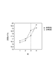
- FIG. 11 shows the flow rates of the degassing units 22 in each row in Reference Examples 1 to 8.
- the flow rate of the deaeration unit 22B in the second row, the flow rate of the deaeration unit 22C in the third row, and the flow rate of the deaeration unit 22D in the fourth row are those of all the deaeration units 22 arranged in each row. The average value of the flow rate was used.
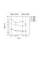
- FIG. 12 is a graph showing the relationship between the flow rate of the deaeration units 22 in each row and the ratio (D2/D1) of the distance D2 to the outer diameter D1 of the deaeration units 22 in Reference Examples 1 to 4. ..
- the flow rate of the degassing unit 22 increases as it approaches the central axis of the housing 23, and the flow rate of the degassing unit 22 decreases as the distance from the central axis of the housing 23 decreases. There is.
- the flow rate of the liquid flowing through the degassing unit 22 tends to decrease as the distance from the central axis of the housing 23 increases, but the outer diameter of the degassing unit 22 increases from the inner peripheral surface of the housing 23 toward the central axis. It was found that the above tendency is reversed in the outer region up to the position corresponding to 0.7 times or 0.5 times D1. That is, it was found that the flow rate of the liquid flowing through the degassing unit 22 tends to be higher in the outer region than in the inner region. Further, it has been found that in the outer region, the flow rate of the liquid flowing to the degassing unit 22 tends to increase as the distance from the central axis of the housing 23 increases (closer to the inner peripheral surface of the housing 23). It was It is presumed that this is because the liquid flowing in the housing 23 is pushed back to the inner peripheral surface of the housing 23 in the outer region, so that the flow rate of the liquid flowing in the degassing unit 22 is increased.
- the pressure loss of the liquid is larger than that of the degassing unit 2 arranged in the inner region 17, which is closest to the outer region 16. By doing so, it is presumed that the deviation of the flow rate of the liquid flowing through each degassing unit 22 can be reduced. Further, in the outer region, the pressure loss of the liquid flowing through the degassing unit 22 increases as the distance from the central axis of the housing 23 increases, thereby reducing the deviation in the flow rate of the liquid flowing through each degassing unit 22. It is presumed that it is possible.
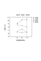
- FIG. 13 is a graph showing the relationship between each column and the flow rate of the degassing unit 22 in Reference Examples 2 and 5.
- Reference Example 2 and Reference Example 5 differ from each other in the degree of overlap between the degassing unit 22 and the inlet 3a when viewed from the direction along the central axis of the housing 23.
- the deaeration unit 22 overlapping the inlet 3 a when viewed from the direction along the central axis of the housing 23 is along the central axis of the housing 23.
- the tendency that the flow rate becomes larger than that of the degassing unit 22 that does not overlap the inlet 3a when viewed from the direction remains the same.
- the inlet 3a overlaps with the degassing unit 22 and the inlet 3a when viewed from the direction along the central axis of the housing 23, regardless of the difference in the overlapping state between the degassing unit 22 and the inlet 3a. It was found that the deaeration unit 22 has a larger flow rate than the deaeration unit 22 that does not overlap the inlet 3a when viewed from the direction along the central axis of the housing 23.
- the degassing unit 22 makes the pressure loss of the liquid larger than that of the degassing unit 22 that does not overlap with the inlet 3a when viewed from the direction along the central axis of the housing 23, so that the liquid flowing through each degassing unit 22 can be separated. It is estimated that the deviation of the flow rate can be reduced.
- FIG. 14 is a graph showing the relationship between the flow rates of the degassing units 22 in each row and the ideal residence time in the upstream region B of the housing 23 in Reference Examples 6 to 8. As shown in FIG. 14, in the reference examples 6 to 8, the ideal residence time in the upstream region B of the housing 23 is different. However, in any of Reference Examples 6 to 8, the tendency that the flow rate of the liquid flowing to the degassing unit 22 increases as the central axis of the housing 23 gets closer does not change.
- the plurality of degassing units 2 are configured such that the pressure loss of the liquid is different depending on the distance from the central axis L of the housing 3, The deviation of the flow rate of the liquid flowing through each degassing unit 22 is reduced to improve the degassing performance of the degassing system 1 as a whole.
- the degassing unit 2 that overlaps the inlet 3a when viewed from the direction along the central axis L is the degassing unit that does not overlap the inlet 3a when viewed from the direction along the central axis L.
- the pressure loss of the liquid may be larger than that of the unit 2 (see Reference Examples 2 and 5 and FIG. 13). In the present specification, the pressure loss refers to the pressure loss of the liquid flowing through the degassing unit 2.
- the predetermined distance D is a distance at which the magnitude relationship of the flow rates of the deaeration units 2 is reversed when the pressure loss of the plurality of deaeration units 2 is the same. From the above consideration 1, the predetermined distance may be 0.7 times the outer diameter D1 of the degassing unit 2 or 0.5 times the outer diameter D1 of the degassing unit 2.
- the plurality of deaeration units 2 are, in the inner region 17, an inner deaeration unit that is any one deaeration unit and an outer deaeration unit 2 that is farther from the central axis L than the inner deaeration unit.
- the deaeration unit may be included, and the inner deaeration unit may be configured so that the pressure loss of the liquid is larger than that of the outer deaeration unit (see Reference Examples 1 to 4 and FIG. 12 ).
- the deaeration unit 2A in the first row is the inner deaeration module
- the deaeration unit 2B in the second row and the deaeration unit in the third row Any one of 2C and the deaeration unit 2D of the 4th row becomes a lower deaeration module.
- the pressure loss of any two deaeration units 2 among the plurality of deaeration units 2 satisfy the above relationship.
- the pressure loss of the degassing units 2 adjacent to each other in the radial direction of the housing 3 may be the same (substantially the same).
- the same pressure loss is meant to include a case where the pressure loss differs by about 30% due to manufacturing error or the like.
- the plurality of deaeration units 2 may be configured so that the pressure loss of the liquid increases as the distance from the central axis L increases.
- the deaeration unit 2 arranged in the inner region 17 is The pressure loss of the liquid may increase as the distance from the central axis L increases.
- the degassing unit 2 arranged in the outer region 16 has a larger pressure loss of liquid than the degassing unit 2 arranged in the inner region 17 that is closest to the outer region 16. May be configured.
- the degassing unit 2 arranged in the outer region 16 may be configured so that the pressure loss of the liquid increases as the distance from the central axis L of the housing 23 increases.
- the pressure loss of the liquid flowing through the degassing unit 2 is, for example, the pressure of the liquid at the supply port 6a (see FIGS. 3 and 4) and the pressure of the liquid at the discharge port 13a of the degassing unit 2 (see FIGS. 3 and 4). Can be obtained by measuring and with a pressure gauge and calculating the difference.
- the pressure loss of the liquid in each degassing unit 2 is, for example, [1] the pressure loss of the liquid in the liquid supply passage 10 (connection supply pipe 6) and [2] the loss of the liquid in the opening 6 b of the connection supply pipe 6.
- connection supply pipe 6 by reducing the inner diameter of the connection supply pipe 6, the pressure loss of the liquid in the liquid supply passage 10 can be increased.
- the connection supply pipe 6 a pipe whose inner diameter is tapered from the upstream side to the downstream side, or a pipe whose inner diameter is gradually reduced from the upstream side to the downstream side.
- the inner diameter of the connection supply pipe 6 may be reduced.
- the pressure loss of the liquid in the hollow fiber membrane bundle 12 can be increased. More specifically, when the density of the plurality of hollow fiber membranes 14 is increased, the gap between the plurality of hollow fiber membranes 14 is narrowed and the passage resistance of the liquid to the hollow fiber membrane bundle 12 is increased. As a result, the pressure loss of the liquid in the hollow fiber membrane bundle 12 increases.
- the pressure loss of the liquid in the hollow fiber membrane bundle 12 can be increased. More specifically, if the thickness of the hollow fiber membrane bundle 12 is increased, the passage resistance of the liquid to the hollow fiber membrane bundle 12 increases. As a result, the pressure loss of the liquid in the hollow fiber membrane bundle 12 increases.
- the hollow fiber membrane bundle 12 is formed by winding a woven fabric in which a plurality of hollow fiber membranes 14 which are wefts are woven with warp threads around the inner tube 11 of the module (around the liquid supply passage 10), for example, degassing
- the liquid pressure loss of the hollow fiber membrane bundle 12 can be increased. More specifically, when the winding pressure of the scroll is increased, the gap between the plurality of hollow fiber membranes 14 is narrowed, and the passage resistance of the liquid to the hollow fiber membrane bundle 12 is increased. As a result, the pressure loss of the liquid in the hollow fiber membrane bundle 12 increases.
- the woven fabric may be wound around the module inner pipe 11 (around the liquid supply passage 10) such that the plurality of hollow fiber membranes 14 extend in the axial direction of the module inner pipe 11 (liquid supply passage 10). ..
- the hollow fiber membrane bundle 12 is a woven fabric in which a plurality of hollow fiber membranes 14 which are wefts are woven with warp yarns, and the plurality of hollow fiber membranes 14 are arranged in the axial direction of the module inner pipe 11 (liquid supply passage 10).
- the module inner tube 11 around the liquid supply passage 10
- the pressure loss of the liquid in the hollow fiber membrane bundle 12 is increased. can do.
- the hollow fiber membranes 14 on the outer peripheral side try to enter between the adjacent hollow fiber membranes 14 on the inner peripheral side.
- the pitch of the warp yarns in the degassing module 5 is short, the space between the outer peripheral hollow fiber membranes 14 supported by the inner peripheral warp yarns becomes narrower, so that the adjacent hollow fiber membranes 14 on the inner peripheral side are adjacent to each other. It becomes difficult to enter. As a result, the density of the hollow fiber membranes 14 becomes low. This reduces the pressure loss of the liquid in the hollow fiber membrane bundle 12.
- the pitch of the warp yarns in the degassing module 5 is long, the hollow fiber membranes 14 on the outer peripheral side have a longer interval supported by the warp yarns on the inner peripheral side. It's easier to get in. As a result, the density of the hollow fiber membranes 14 increases. As a result, the pressure loss of the liquid in the hollow fiber membrane bundle 12 increases.
- the pressure loss of the liquid in the hollow fiber membrane bundle 12 can be increased. More specifically, for example, when the number of the hollow fiber membranes 14 is the same, if the outer diameter of the hollow fiber membranes 14 is increased, the gap between the hollow fiber membranes 14 is narrowed, and the passage of the liquid to the hollow fiber membrane bundle 12 passes. The resistance increases. As a result, the pressure loss of the liquid in the hollow fiber membrane bundle 12 increases.
- the pressure loss of the liquid in the hollow fiber membrane bundles 12 can be increased. More specifically, as the hydrophilicity of the hollow fiber membrane 14 increases, the contact resistance of the liquid to the hollow fiber membrane 14 increases. As a result, the pressure loss of the liquid in the hollow fiber membrane bundle 12 increases.
- a plurality of degassing units 2 are accommodated in parallel in a cylindrical housing 3.
- the pressure loss of the liquid flowing through the plurality of degassing units 2 is the same, the flow rate of the liquid flowing through the degassing unit 2 differs depending on the distance from the central axis L of the housing 3.
- the plurality of degassing units 2 are configured so that the pressure loss of the liquid varies depending on the distance from the central axis L of the housing 3. This difference in pressure loss serves to offset the above difference in flow rate. Thereby, it is possible to reduce the deviation of the flow rate of the liquid flowing through the plurality of degassing units 2. As a result, for example, the degassing performance of the entire degassing system 1 can be improved.
- the liquid can be appropriately degassed in the degassing unit 2, and the degassed gas can be appropriately discharged to the outside of the housing 3.
- the degassing unit 2 that overlaps the inlet 3a when viewed from the direction along the central axis L has a stronger liquid supply pressure from the inlet 3a than the degassing unit 2 that does not overlap the inlet 3a when viewed from the direction along the central axis L. As it receives the liquid, it becomes easier for the liquid to flow. Therefore, the degassing unit 2 overlapping the inlet 3a when viewed from the direction along the central axis L has a larger liquid pressure loss than the degassing unit 2 that does not overlap the inlet 3a when viewed from the direction along the central axis L. By doing so, the difference in pressure loss acts to cancel the difference in supply pressure of the liquid. As a result, it is possible to reduce the deviation in the flow rate of the liquid flowing through the degassing unit 2.
- the difference in pressure loss acts to offset the above difference in flow rate. Accordingly, it is possible to reduce the difference in the flow rate of the liquid flowing through the inner degassing unit and the outer degassing unit.
- the pressure loss of the liquid increases as the plurality of deaeration units 2 move away from the central axis L, and thus a plurality of the deaeration units 2 are formed.
- the deviation of the flow rate of the liquid flowing through the degassing unit 2 can be appropriately reduced.
- the deaeration unit 2 arranged in the inner region 17 is the center. Since the pressure loss of the liquid increases as the distance from the axis L increases, the difference in the flow rate of the liquid flowing through the degassing unit 2 in the inner region 17 can be appropriately reduced.
- the degassing unit 2 arranged in the outer region 16 has a larger pressure loss of the liquid than the degassing unit 2 arranged in the inner region 17 that is closest to the outer region 16.
- the difference in the flow rate of the liquid can be appropriately reduced between the degassing unit 2 arranged in the inner region 17 and the degassing unit 2 arranged in the outer region 16.
- one deaeration unit 2 is composed of a plurality of deaeration modules 5 like the deaeration unit 2A shown in FIG. 3, first, a plurality of deaeration modules 5 and a connection supply pipe 6 are prepared. To do. Next, the connection supply pipe 6 is inserted into the liquid supply paths 10 of the plurality of degassing modules 5. Then, the liquid supply paths 10 of the plurality of degassing modules 5 are connected in series by the connection supply pipe 6. Further, the plurality of openings 6b of the connection supply pipe 6 are arranged at the positions corresponding to the plurality of degassing modules 5 so that the liquid is supplied in parallel to the hollow fiber membrane bundles 12 of the plurality of degassing modules 5. Thereby, one deaeration unit 2 is formed. If one degassing unit 2 is composed of one degassing module 5 like the degassing unit 2B shown in FIG. 4, such a procedure is not necessary.
- each deaeration module has been described as including the module inner pipe, but such a module inner pipe may not be provided.
- the hollow fiber membrane bundle (fabric) of each degassing module is directly wound around the connection supply pipe.
- the method and method of using the degassing system of the present invention are not particularly limited, and for example, to produce natural resources such as jet boring method, in situ leaching method (ISL), and waterflooding method.
- ISL in situ leaching method
- this method for producing natural resources is, in the degassing system of the present invention, supplying liquid to the plurality of degassing units from the inlet and depressurizing the inside of the plurality of hollow fiber membranes of each of the plurality of degassing modules. By doing so, a step of degassing the liquid and a step of press-fitting the liquid degassed in the degassing step into the natural resource mining site are provided.
- examples of the natural resources include metal minerals such as copper and uranium, and fuel minerals such as crude oil, natural gas, shale oil, and shale gas.
- examples of the liquid include water.
- examples of the natural resource is a fuel mineral
- examples of the liquid include seawater, associated water, and fracturing fluid.
- Associated water is water produced when producing natural resources.
- the deaeration unit used in the present invention may be manufactured by connecting a plurality of deaeration modules in advance and then transferred to a place of use, or the deaeration modules conveyed individually may be deaerated according to the present invention. It can also be connected and manufactured at the place of use of the system. In the unlikely event that any degassing module or degassing unit fails, only the corresponding degassing module or degassing unit needs to be replaced. It has excellent maintenance. Therefore, for example, it is suitable for use at a mining site for natural resources.
Landscapes
- Chemical Kinetics & Catalysis (AREA)
- Chemical & Material Sciences (AREA)
- Engineering & Computer Science (AREA)
- Mining & Mineral Resources (AREA)
- Life Sciences & Earth Sciences (AREA)
- Geology (AREA)
- Manufacturing & Machinery (AREA)
- Physics & Mathematics (AREA)
- Environmental & Geological Engineering (AREA)
- Fluid Mechanics (AREA)
- General Life Sciences & Earth Sciences (AREA)
- Geochemistry & Mineralogy (AREA)
- Separation Using Semi-Permeable Membranes (AREA)
- Degasification And Air Bubble Elimination (AREA)
Abstract
Priority Applications (8)
| Application Number | Priority Date | Filing Date | Title |
|---|---|---|---|
| AU2019413100A AU2019413100B2 (en) | 2018-12-28 | 2019-12-24 | Degassing system, method for degassing liquids, degassing unit, degassing module, and degassing-system manufacturing method and method of production from natural resources |
| CA3124331A CA3124331A1 (fr) | 2018-12-28 | 2019-12-24 | Systeme de degazage presentant des chutes de pression en fonction de la distance |
| MYPI2021003460A MY198365A (en) | 2018-12-28 | 2019-12-24 | Degassing System, Method for Degassing Liquids, Degassing unit, Degassing Module, And Degassing-System Manufacturing Method and Method of Production from Natural Resources |
| US17/417,976 US20220062794A1 (en) | 2018-12-28 | 2019-12-24 | Degassing system, method for degassing liquids, degassing unit, degassing module, and degassing-system manufacturing method and method of production from natural resources |
| JP2020560854A JP6973665B2 (ja) | 2018-12-28 | 2019-12-24 | 脱気システム、液体の脱気方法、脱気ユニット、脱気モジュール、脱気システムの製造方法、及び天然資源の産生方法 |
| CN201980085484.5A CN113226507B (zh) | 2018-12-28 | 2019-12-24 | 脱气系统及其制造方法、液体的脱气方法、脱气单元、脱气模块、及天然资源的生产方法 |
| MX2021007730A MX2021007730A (es) | 2018-12-28 | 2019-12-24 | Sistema de desgasificacion, metodo para desgasificar liquidos, unidades de desgasificacion, modulo de desgasificacion y metodo de fabricacion de sistema de desgasificacion y metodo de produccion a partir de recursos naturales. |
| EP19901994.4A EP3903899B1 (fr) | 2018-12-28 | 2019-12-24 | Système de dégazage, procédé de dégazage de liquides et procédé de fabrication de système de dégazage |
Applications Claiming Priority (2)
| Application Number | Priority Date | Filing Date | Title |
|---|---|---|---|
| JP2018246967 | 2018-12-28 | ||
| JP2018-246967 | 2018-12-28 |
Publications (1)
| Publication Number | Publication Date |
|---|---|
| WO2020138096A1 true WO2020138096A1 (fr) | 2020-07-02 |
Family
ID=71129485
Family Applications (1)
| Application Number | Title | Priority Date | Filing Date |
|---|---|---|---|
| PCT/JP2019/050650 Ceased WO2020138096A1 (fr) | 2018-12-28 | 2019-12-24 | Système de dégazage, procédé de dégazage de liquides, unité de dégazage, module de dégazage, et procédé de fabrication de système de dégazage et procédé de production à partir de ressources naturelles |
Country Status (9)
| Country | Link |
|---|---|
| US (1) | US20220062794A1 (fr) |
| EP (1) | EP3903899B1 (fr) |
| JP (1) | JP6973665B2 (fr) |
| CN (1) | CN113226507B (fr) |
| AU (1) | AU2019413100B2 (fr) |
| CA (1) | CA3124331A1 (fr) |
| MX (1) | MX2021007730A (fr) |
| MY (1) | MY198365A (fr) |
| WO (1) | WO2020138096A1 (fr) |
Cited By (4)
| Publication number | Priority date | Publication date | Assignee | Title |
|---|---|---|---|---|
| GB2604591A (en) * | 2021-03-02 | 2022-09-14 | Veolia Water Solutions & Tech | Membrane contactor assembly for degassing a liquid |
| WO2025158865A1 (fr) * | 2024-01-23 | 2025-07-31 | Dic株式会社 | Module de dégazage et procédé de dégazage de liquide |
| TWI914122B (zh) | 2024-01-23 | 2026-02-01 | 日商Dic股份有限公司 | 脫氣模組及液體的脫氣方法 |
| JP7827236B1 (ja) * | 2024-09-05 | 2026-03-10 | Dic株式会社 | 中空糸膜エレメント、中空糸膜モジュール、脱気方法、及びガス付加方法 |
Families Citing this family (1)
| Publication number | Priority date | Publication date | Assignee | Title |
|---|---|---|---|---|
| MX2021003469A (es) * | 2018-09-27 | 2021-06-18 | Dainippon Ink & Chemicals | Sistema de desgasificacion, metodo de desgasificacion de liquidos, modulo de desgasificacion, metodo para fabricar un sistema de desgasificacion, y metodo para producir recursos naturales. |
Citations (7)
| Publication number | Priority date | Publication date | Assignee | Title |
|---|---|---|---|---|
| JPS57102201A (en) * | 1980-12-18 | 1982-06-25 | Toyobo Co Ltd | Perm selective hollow fiber assembly |
| JPS61222509A (ja) * | 1985-03-28 | 1986-10-03 | Japan Organo Co Ltd | 中空糸モジュ−ルを用いる濾過塔 |
| JPH11226368A (ja) * | 1998-02-17 | 1999-08-24 | Kyocera Corp | 脱気用セラミック複合部材並びにそれを用いた脱気方法 |
| JP2003033629A (ja) * | 2001-07-23 | 2003-02-04 | Kitz Corp | 中空糸膜を用いた濾過装置 |
| JP2007253105A (ja) * | 2006-03-24 | 2007-10-04 | Sekiyu Combinat Kodo Togo Unei Gijutsu Kenkyu Kumiai | 気体放散構造及び気液分離装置 |
| JP4593719B2 (ja) | 1999-03-08 | 2010-12-08 | セルガード,インコーポレイテッド | シェルレス中空糸膜流体接触器 |
| WO2015012293A1 (fr) * | 2013-07-24 | 2015-01-29 | 三菱レイヨン株式会社 | Module de membrane à fibres creuses de perfusion externe et imprimante à jet d'encre dotée dudit module |
Family Cites Families (15)
| Publication number | Priority date | Publication date | Assignee | Title |
|---|---|---|---|---|
| JP3370407B2 (ja) * | 1993-12-24 | 2003-01-27 | 三菱レイヨン株式会社 | ガス交換用中空糸膜モジュール |
| US20020168491A1 (en) * | 2001-05-08 | 2002-11-14 | Runkle Charles J. | Hollow fiber membrane contactor and method for making same |
| JP2004082073A (ja) * | 2002-08-29 | 2004-03-18 | Daicen Membrane Systems Ltd | 中空糸膜モジュール |
| CN100402123C (zh) * | 2003-05-01 | 2008-07-16 | 安格斯公司 | 带脱气机构的过滤单元 |
| AU2006251862B2 (en) * | 2005-05-25 | 2011-12-01 | Curtin University Of Technology | Improved method for desalination |
| JP5731093B2 (ja) * | 2005-11-30 | 2015-06-10 | コニカミノルタ株式会社 | インクジェットインクの脱気方法およびインクジェットインクの製造方法 |
| JP5080781B2 (ja) * | 2006-11-06 | 2012-11-21 | 三菱レイヨン株式会社 | 脱気用中空糸膜モジュール及び脱気装置 |
| US8506685B2 (en) * | 2009-08-17 | 2013-08-13 | Celgard Llc | High pressure liquid degassing membrane contactors and methods of manufacturing and use |
| DE102010032736B4 (de) * | 2010-07-30 | 2012-07-26 | Sartorius Stedim Biotech Gmbh | Vorrichtung und Verfahren zur Entgasung wässriger Medien |
| KR20150091891A (ko) * | 2014-02-04 | 2015-08-12 | 주식회사 디피케이 | 비결정질 불소수지 중공사튜브를 이용한 탈기장치 및 그 제조법 |
| JP3195924U (ja) * | 2014-11-28 | 2015-02-12 | Dic株式会社 | 中空糸脱気モジュール及びインクジェットプリンタ |
| ES3036074T3 (en) * | 2014-12-24 | 2025-09-12 | Dainippon Ink & Chemicals | Hollow-fiber degassing module and inkjet printer |
| CN106999799B (zh) * | 2014-12-24 | 2020-07-03 | Dic株式会社 | 中空纤维脱气组件以及喷墨打印机 |
| JP6462131B2 (ja) * | 2016-05-11 | 2019-01-30 | 三菱ケミカル・クリンスイ株式会社 | 中空糸膜モジュール |
| CA3023277C (fr) * | 2016-06-30 | 2020-11-10 | Dic Corporation | Module de degazage a fibres creuses et procede de degazage de liquide utilisant ledit module de degazage a fibres creuses |
-
2019
- 2019-12-24 MX MX2021007730A patent/MX2021007730A/es unknown
- 2019-12-24 EP EP19901994.4A patent/EP3903899B1/fr active Active
- 2019-12-24 WO PCT/JP2019/050650 patent/WO2020138096A1/fr not_active Ceased
- 2019-12-24 CA CA3124331A patent/CA3124331A1/fr active Pending
- 2019-12-24 AU AU2019413100A patent/AU2019413100B2/en active Active
- 2019-12-24 JP JP2020560854A patent/JP6973665B2/ja active Active
- 2019-12-24 CN CN201980085484.5A patent/CN113226507B/zh active Active
- 2019-12-24 US US17/417,976 patent/US20220062794A1/en active Pending
- 2019-12-24 MY MYPI2021003460A patent/MY198365A/en unknown
Patent Citations (7)
| Publication number | Priority date | Publication date | Assignee | Title |
|---|---|---|---|---|
| JPS57102201A (en) * | 1980-12-18 | 1982-06-25 | Toyobo Co Ltd | Perm selective hollow fiber assembly |
| JPS61222509A (ja) * | 1985-03-28 | 1986-10-03 | Japan Organo Co Ltd | 中空糸モジュ−ルを用いる濾過塔 |
| JPH11226368A (ja) * | 1998-02-17 | 1999-08-24 | Kyocera Corp | 脱気用セラミック複合部材並びにそれを用いた脱気方法 |
| JP4593719B2 (ja) | 1999-03-08 | 2010-12-08 | セルガード,インコーポレイテッド | シェルレス中空糸膜流体接触器 |
| JP2003033629A (ja) * | 2001-07-23 | 2003-02-04 | Kitz Corp | 中空糸膜を用いた濾過装置 |
| JP2007253105A (ja) * | 2006-03-24 | 2007-10-04 | Sekiyu Combinat Kodo Togo Unei Gijutsu Kenkyu Kumiai | 気体放散構造及び気液分離装置 |
| WO2015012293A1 (fr) * | 2013-07-24 | 2015-01-29 | 三菱レイヨン株式会社 | Module de membrane à fibres creuses de perfusion externe et imprimante à jet d'encre dotée dudit module |
Cited By (6)
| Publication number | Priority date | Publication date | Assignee | Title |
|---|---|---|---|---|
| GB2604591A (en) * | 2021-03-02 | 2022-09-14 | Veolia Water Solutions & Tech | Membrane contactor assembly for degassing a liquid |
| WO2025158865A1 (fr) * | 2024-01-23 | 2025-07-31 | Dic株式会社 | Module de dégazage et procédé de dégazage de liquide |
| JPWO2025158865A1 (fr) * | 2024-01-23 | 2025-07-31 | ||
| TWI914122B (zh) | 2024-01-23 | 2026-02-01 | 日商Dic股份有限公司 | 脫氣模組及液體的脫氣方法 |
| JP7827236B1 (ja) * | 2024-09-05 | 2026-03-10 | Dic株式会社 | 中空糸膜エレメント、中空糸膜モジュール、脱気方法、及びガス付加方法 |
| WO2026053703A1 (fr) * | 2024-09-05 | 2026-03-12 | Dic株式会社 | Élément de membrane à fibres creuses, module de membrane à fibres creuses, procédé de désaération, et procédé d'ajout de gaz |
Also Published As
| Publication number | Publication date |
|---|---|
| AU2019413100A1 (en) | 2021-08-12 |
| MY198365A (en) | 2023-08-28 |
| JPWO2020138096A1 (ja) | 2021-02-18 |
| AU2019413100B2 (en) | 2022-11-17 |
| EP3903899A1 (fr) | 2021-11-03 |
| CN113226507B (zh) | 2023-01-13 |
| MX2021007730A (es) | 2021-08-24 |
| US20220062794A1 (en) | 2022-03-03 |
| JP6973665B2 (ja) | 2021-12-01 |
| CA3124331A1 (fr) | 2020-07-02 |
| CN113226507A (zh) | 2021-08-06 |
| EP3903899A4 (fr) | 2022-05-11 |
| EP3903899B1 (fr) | 2025-01-29 |
Similar Documents
| Publication | Publication Date | Title |
|---|---|---|
| JP6973665B2 (ja) | 脱気システム、液体の脱気方法、脱気ユニット、脱気モジュール、脱気システムの製造方法、及び天然資源の産生方法 | |
| JP2022000302A (ja) | 脱気システム、液体の脱気方法、脱気モジュール、脱気システムの製造方法、及び天然資源の産生方法 | |
| JP4531091B2 (ja) | 円筒形ろ過カートリッジを保持する圧力容器 | |
| EP3639912B1 (fr) | Module à membranes à fibres creuses du type à circulation externe | |
| KR20140009160A (ko) | 다중-리프 역삼투 엘리먼트 | |
| WO2018003840A1 (fr) | Module de dégazage à fibres creuses et procédé de dégazage de liquide utilisant ledit module de dégazage à fibres creuses | |
| EP4458444A1 (fr) | Module de dégazage, et procédé de dégazage de liquide | |
| EP3659694A1 (fr) | Module à membranes à fibres creuses | |
| CN118382494A (zh) | 脱气组件及液体的脱气方法 | |
| US11000808B2 (en) | Sheet-shaped hollow fiber membrane module and membrane separation unit | |
| EP3434348B1 (fr) | Dispositifs de dégazage de fluides présentant des profilés sélectionnés | |
| WO2011150206A2 (fr) | Module à fibres creuses | |
| JP7827235B1 (ja) | 脱気モジュール及び液体の脱気方法 | |
| JP7827237B1 (ja) | 液体の脱気方法及び脱気モジュール | |
| JP2017056369A (ja) | 分離膜モジュール | |
| WO2025150434A1 (fr) | Élément de désaération, module de désaération, et procédé de désaération de liquide | |
| WO2024262314A1 (fr) | Module de dégazage et procédé de dégazage de liquide | |
| BR112021010424A2 (pt) | Dispositivo de filtro, unidade de filtro de membrana, uso de dispositivo de filtro, e, método para instalar uma pluralidade de unidades de filtro de membrana |
Legal Events
| Date | Code | Title | Description |
|---|---|---|---|
| 121 | Ep: the epo has been informed by wipo that ep was designated in this application |
Ref document number: 19901994 Country of ref document: EP Kind code of ref document: A1 |
|
| ENP | Entry into the national phase |
Ref document number: 2020560854 Country of ref document: JP Kind code of ref document: A |
|
| ENP | Entry into the national phase |
Ref document number: 3124331 Country of ref document: CA |
|
| NENP | Non-entry into the national phase |
Ref country code: DE |
|
| ENP | Entry into the national phase |
Ref document number: 2019901994 Country of ref document: EP Effective date: 20210728 |
|
| ENP | Entry into the national phase |
Ref document number: 2019413100 Country of ref document: AU Date of ref document: 20191224 Kind code of ref document: A |
|
| WWG | Wipo information: grant in national office |
Ref document number: MX/A/2021/007730 Country of ref document: MX |