WO2020144985A1 - Bloc-batterie - Google Patents
Bloc-batterie Download PDFInfo
- Publication number
- WO2020144985A1 WO2020144985A1 PCT/JP2019/047686 JP2019047686W WO2020144985A1 WO 2020144985 A1 WO2020144985 A1 WO 2020144985A1 JP 2019047686 W JP2019047686 W JP 2019047686W WO 2020144985 A1 WO2020144985 A1 WO 2020144985A1
- Authority
- WO
- WIPO (PCT)
- Prior art keywords
- housing
- relay
- heat dissipation
- battery pack
- heat
- Prior art date
- Legal status (The legal status is an assumption and is not a legal conclusion. Google has not performed a legal analysis and makes no representation as to the accuracy of the status listed.)
- Ceased
Links
Images




Classifications
-
- H—ELECTRICITY
- H01—ELECTRIC ELEMENTS
- H01M—PROCESSES OR MEANS, e.g. BATTERIES, FOR THE DIRECT CONVERSION OF CHEMICAL ENERGY INTO ELECTRICAL ENERGY
- H01M50/00—Constructional details or processes of manufacture of the non-active parts of electrochemical cells other than fuel cells, e.g. hybrid cells
- H01M50/20—Mountings; Secondary casings or frames; Racks, modules or packs; Suspension devices; Shock absorbers; Transport or carrying devices; Holders
- H01M50/204—Racks, modules or packs for multiple batteries or multiple cells
- H01M50/207—Racks, modules or packs for multiple batteries or multiple cells characterised by their shape
- H01M50/209—Racks, modules or packs for multiple batteries or multiple cells characterised by their shape adapted for prismatic or rectangular cells
-
- H—ELECTRICITY
- H01—ELECTRIC ELEMENTS
- H01H—ELECTRIC SWITCHES; RELAYS; SELECTORS; EMERGENCY PROTECTIVE DEVICES
- H01H50/00—Details of electromagnetic relays
- H01H50/12—Ventilating; Cooling; Heating
-
- H—ELECTRICITY
- H05—ELECTRIC TECHNIQUES NOT OTHERWISE PROVIDED FOR
- H05K—PRINTED CIRCUITS; CASINGS OR CONSTRUCTIONAL DETAILS OF ELECTRIC APPARATUS; MANUFACTURE OF ASSEMBLAGES OF ELECTRICAL COMPONENTS
- H05K7/00—Constructional details common to different types of electric apparatus
- H05K7/20—Modifications to facilitate cooling, ventilating, or heating
-
- Y—GENERAL TAGGING OF NEW TECHNOLOGICAL DEVELOPMENTS; GENERAL TAGGING OF CROSS-SECTIONAL TECHNOLOGIES SPANNING OVER SEVERAL SECTIONS OF THE IPC; TECHNICAL SUBJECTS COVERED BY FORMER USPC CROSS-REFERENCE ART COLLECTIONS [XRACs] AND DIGESTS
- Y02—TECHNOLOGIES OR APPLICATIONS FOR MITIGATION OR ADAPTATION AGAINST CLIMATE CHANGE
- Y02E—REDUCTION OF GREENHOUSE GAS [GHG] EMISSIONS, RELATED TO ENERGY GENERATION, TRANSMISSION OR DISTRIBUTION
- Y02E60/00—Enabling technologies; Technologies with a potential or indirect contribution to GHG emissions mitigation
- Y02E60/10—Energy storage using batteries
Definitions
- the present disclosure relates to a battery pack.
- Patent Document 1 An invention relating to a battery module for a vehicle has been conventionally known (see Patent Document 1 below).
- An object of the invention described in Patent Document 1 is to radiate heat in the entire shield case and in the junction box when the junction box is housed in the shield case that houses the battery pack.
- Patent Document 1 discloses a battery module having the following configuration (see the same document, claim 1, paragraph 0009, etc.).
- a junction box is housed inside a metal shield case that houses the battery pack, and the resin case of the junction box is mounted on the bottom wall of the shield case. Further, a fan is attached to the wall of the shield case, and an exhaust port for discharging the air flowing through the inside of the shield case is provided. Further, the case of the junction box is provided with a ventilation hole so that a part of the air flowing into the shield case is circulated in the case of the junction box.
- the relay is arranged so as to be exposed on the upper surface of the case of the junction box (see the same document, claim 2, paragraph 0010, etc.).
- the junction box is mounted with the relay exposed on the surface of the case made of resin molded product. More specifically, the case is mounted on the upper surface of the upper case with a relay including a lower case that is formed of side walls on the front, rear, left, and right sides with an opening on the lower surface, and an upper case that is lock-coupled to the upper part of the lower case (ibid. (See paragraph 0015, FIGS. 1 and 2, etc.).
- the high voltage relay is directly fixed on a metal plate laid on the bottom wall of the shield case of the battery module.
- the heat generated in the high-voltage relay can be directly conducted to the bottom wall of the shield case through the metal plate to radiate the heat (see the same document, paragraphs 0021 and 0022, FIG. 3, etc.).
- the metal plate conducts the heat generated in the high-voltage relay to the bottom wall of the shield case to radiate the heat.
- the heat conduction path of this metal plate connects the high-voltage relay and the bottom wall of the shield case with the shortest distance, the bottom wall of the shield case locally becomes hot due to the heat generated in the high-voltage relay. There is a risk of becoming.
- the present disclosure provides a battery pack that can radiate the heat generated in the relay to the housing by heat conduction and can prevent the housing from becoming locally high in temperature.
- One aspect of the present disclosure is a battery pack including a housing, a plurality of battery cells housed in the housing, and a relay connected to the plurality of battery cells, wherein the battery pack is generated in the relay.
- a battery pack comprising a heat dissipation member that conducts heat and dissipates heat, and the heat dissipation member forms a heat conduction path longer than a shortest distance between the relay and the housing.
- the heat dissipation member can form a heat conduction path longer than the shortest distance between the relay and the case between the relay and the case. Therefore, the heat generated in the relay can be radiated to the housing by heat conduction via the heat conduction path, and a battery pack capable of suppressing the housing from locally becoming high temperature is provided. be able to.
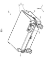
- FIG. 1 is a perspective view of a battery pack according to an embodiment of the present disclosure.
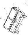
- FIG. 2 is a perspective view of the battery pack shown in FIG. 1 with a cover removed.
- FIG. 2 is an exploded perspective view of the battery module housed in the housing of the battery pack shown in FIG. 1.
- FIG. 3 is a perspective view of an electrical component holder housed in the housing of the battery pack shown in FIG. 1.
- FIG. 3 is a perspective view showing a positional relationship between a heat dissipation member and a relay of the battery pack shown in FIG. 2.
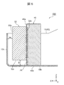
- the expanded sectional view which follows the VI-VI line shown in FIG.
- the perspective view which concerns on the modification 2 of the battery pack shown in FIG. The expanded sectional view which follows the IX-IX line of FIG.
- FIG. 1 is a perspective view of a battery pack 100 according to this embodiment.
- FIG. 2 is a perspective view of the battery pack 100 shown in FIG. 1 with the cover 12 of the housing 10 removed.
- FIG. 3 is an exploded perspective view of the battery module 20 housed in the housing 10 of the battery pack 100 shown in FIG.
- FIG. 4 is a perspective view of the electrical component holder 30 housed in the housing 10 of the battery pack 100 shown in FIG.
- the battery pack 100 shown in FIG. 2 is in a state in which not only the cover 12 but also accessories such as the electrical component holder 30 shown in FIG. 4 are removed.
- the battery pack 100 of the present embodiment mainly has the following configuration.
- the battery pack 100 includes a housing 10, a plurality of battery cells 1 housed in the housing 10, and a relay 32 connected to the plurality of battery cells 1. Further, the battery pack 100 includes a heat dissipation member 40 that conducts the heat generated in the relay 32 and dissipates the heat.
- the heat dissipation member 40 forms a heat conduction path Pt longer than the shortest distance Ds between the relay 32 and the housing 10 (see FIG. 6).
- the configuration of each part of the battery pack 100 of this embodiment will be described in detail below.
- the battery pack 100 of the present embodiment includes, for example, a housing 10, a battery module 20, an electrical component holder 30, and a heat dissipation member 40.
- the housing 10 has, for example, a substantially rectangular parallelepiped shape, and is a box shape whose vertical dimension is larger than its horizontal dimension and height dimension.
- a battery is formed using an orthogonal coordinate system including an X axis parallel to the lateral direction of the housing 10, a Y axis parallel to the vertical direction of the housing 10, and a Z axis parallel to the height direction of the housing 10.
- Each part of the pack 100 may be described.
- the housing 10 has, for example, a rectangular box-shaped main body 11 having an open top, and a lid-shaped cover 12 that closes an opening at the top of the main body 11.
- the material of the main body 11 is, for example, a metal material such as electrogalvanized steel sheet
- the material of the cover 12 is, for example, a resin material such as polybutylene terephthalate (PBT).
- the main body 11 shown in FIG. 2 accommodates the battery module 20 on one side in the horizontal direction ( ⁇ X direction side), and the electric component holder 30 shown in FIG. 4 in the space on the other side in the horizontal direction (+X direction side). Then, the heat dissipation member 40 is housed between the battery module 20 and the electrical component holder 30.
- a pair of high voltage terminals 101 which are external terminals, are exposed in the opening of the cover 12.
- the battery pack 100 is supplied with power from an external device via the high voltage terminal 101, and supplies power to the external device via the high voltage terminal 101.
- the cover 12 is, for example, a concave portion on the inner side in the vertical direction (on the ⁇ Y direction side) of the corner on the one side in the horizontal direction (on the +X direction side) and on the one side in the vertical direction (on the +Y direction side) where the high voltage terminal 101 is arranged.
- an opening for exposing the signal connector 102 is formed in the recess.
- the signal connector 102 is exposed at the opening of the cover 12.
- the battery pack 100 is connected via a signal connector 102 to, for example, an electronic control unit mounted on a vehicle.
- the signal connector 102 is, for example, a connector for control signals of the battery pack 100, and inputs/outputs information and receives power.
- the battery module 20 for example, as shown in FIG. 2, is housed inside the housing 10 on one lateral side ( ⁇ X direction side) and is fixed to the housing 10 by a fastening member such as a bolt.
- the battery module 20 holds a plurality of flat rectangular battery cells 1 and a plurality of battery cells 1 by holding each battery cell 1 from both sides in the thickness direction (Z direction). And a plurality of cell holders 22 that are stacked in the vertical direction (Z direction).
- the battery module 20 includes a bus bar 21 (see FIG. 2) that connects the plurality of battery cells 1, and a pair of end plates 23 that are arranged at both ends in the stacking direction of the plurality of battery cells 1 via cell holders 22, And a plurality of connecting portions 24 that connect the pair of end plates 23.
- the battery module 20 includes a bus bar case 25 (see FIG. 2) arranged to face the battery lid 1d along the thickness direction (Z direction) of the plurality of battery cells 1.
- the plurality of battery cells 1 have a generally rectangular parallelepiped flat rectangular shape, and are stacked in the thickness direction (Z direction) and housed in the housing 10.
- the battery cell 1 is, for example, a prismatic lithium ion secondary battery.
- the battery cell 1 includes a flat rectangular battery can 1c, a battery lid 1d that closes the opening of the battery can 1c, an electrode group and an electrolyte solution (not shown) housed in the battery can 1c, and an electrode group thereof. And a pair of external terminals 1g connected and attached to the battery lid 1d.
- the battery can 1c is a flat, bottomed, square-tube container having an opening at one end, and the bottom is covered with an insulating film 1f.
- the insulating film 1f is a resin film having electrical insulation, and electrically insulates the housing 10 and the battery cell 1 from each other, for example.
- the battery lid 1d is, for example, a generally rectangular plate-shaped member, and is joined to the opening of the battery can 1c by laser welding over the entire circumference to seal the battery can 1c.
- the battery can 1c and the battery lid 1d constitute a battery container that accommodates and seals the electrode group and the electrolytic solution.
- the battery lid 1d has, for example, a safety valve 1v that cleaves to release the gas inside the battery cell 1 when the internal pressure of the battery cell 1 rises above a prescribed pressure.
- the electrode group is, for example, a wound electrode group in which a long strip-shaped positive electrode and a long strip-shaped negative electrode are faced to each other via a separator that is a long strip-shaped insulating member and wound.
- the positive electrodes forming the electrode group are connected to the positive electrode external terminal 1g via a positive electrode current collector plate, for example.
- the negative electrodes forming the electrode group are connected to the negative electrode external terminal 1g via a negative electrode current collector plate, for example.
- the electrolytic solution is contained in the battery can 1c by being injected into the inside of the battery can 1c from a liquid injection port provided in the battery lid 1d, and is impregnated in the electrode group.
- the battery can 1c is sealed by the battery lid 1d by joining the liquid injection plug 1k to the liquid injection port of the battery lid 1d by, for example, laser welding after the injection of the electrolytic solution.
- the bus bar 21 is, for example, a plate-shaped member made of a metal having conductivity such as aluminum or copper, and is joined to the external terminal 1g of the battery cell 1 by laser welding or ultrasonic joining, and is external to the adjacent battery cell 1.
- the terminals 1g are electrically connected.
- the battery module 20 has, for example, as shown in FIG. 3, two rows of battery rows including a plurality of flat rectangular battery cells 1 stacked in the height direction (Z direction) of the battery pack 100. Two battery rows in which the battery cells 1 are stacked in the thickness direction (Z direction) are arranged in the width direction (Y direction) of the battery cells 1.
- the cell holder 22 is configured to hold the battery cells 1 from both sides in the thickness direction (Z direction) and stack the plurality of battery cells 1 in the thickness direction.
- the cell holder 22 is made of, for example, an engineering plastic having electrical insulation properties such as polybutylene terephthalate (PBT), is interposed between the battery cells 1 and 1, and the space between the battery cells 1 is 1. It functions as an insulating separator or a spacer for providing a gap between the battery cells 1.
- PBT polybutylene terephthalate
- the pair of end plates 23 are plate-shaped members arranged on both sides of the plurality of battery cells 1 in the stacking direction, and sandwich the plurality of battery cells 1 from both sides in the stacking direction via the cell holder 22.
- the pair of end plates 23 is fixed to the plurality of connecting portions 24 by fastening members such as bolts in a state where a compressive force is applied in the stacking direction of the plurality of battery cells 1, for example.
- the plurality of connecting portions 24 form, for example, a second path Pt2 (see FIG. 5) that is a part of the heat conduction path Pt that conducts the heat generated in the relay 32 to the housing 10. ..
- the connecting portion 24 is, for example, a plate-shaped or block-shaped metal member, and is arranged so as to face both side surfaces of the plurality of battery cells 1 facing the width direction (Y direction). More specifically, the battery module 20 includes a pair of connecting portions 24 as side plates arranged so as to sandwich the two battery rows from both sides in the width direction of the battery cell 1, and the two battery rows. It has the connection part 24 as a center plate arranged.
- Each of the connecting portions 24 has, for example, a convex portion that projects in the height direction (+X direction) of the battery cell 1.
- This convex portion is fixed to the heat dissipation member 40 shown in FIG. 2 via a fastening member such as a bolt.
- the connecting portions 24, which are a pair of side plates facing the side walls 10c at both ends of the housing 10 in the vertical direction, are fixed to the housing 10 via fastening members such as bolts.
- the connecting portion 24 and the housing 10 are in contact with each other, and heat conduction is possible between them.
- the busbar case 25 is arranged, for example, so as to engage with a protrusion-shaped engaging portion provided on the cell holder 22 and cover an end surface of the plurality of battery cells 1 provided with the external terminals 1g.
- the bus bar case 25 is, for example, a rectangular frame-shaped member made of engineering plastic such as PBT similar to the cell holder 22, and has a plurality of openings for exposing the external terminals 1g of the battery cells 1.
- the busbar case 25 insulates the busbars 21 adjacent to each other by a partition wall, for example.
- the electrical component holder 30, for example, as shown in FIG. 4, holds a control board 31, a relay 32, a fuse 33, a shunt resistor 34, and a pair of connection terminals 35.
- the control board 31 is fixed to the surface of the electric component holder 30 facing the battery module 20 with bolts, for example.
- the shunt resistor 34 is fixed to the control board 31 with a screw, for example, and is arranged in the current path between the negative connection terminal 35 and the negative high voltage terminal 101.
- the control board 31 is connected to, for example, each bus bar 21 that connects the battery cells 1 adjacent to each other in the stacking direction via a voltage detection line.
- the control board 31 includes, for example, a control circuit that measures and monitors the voltage of each battery cell 1 and controls and monitors the entire battery pack 100.
- the relay 32 and the fuse 33 are fixed to the electrical component holder 30 with, for example, screws and are arranged in the current path between the positive connection terminal 35 and the positive high voltage terminal 101.
- the relay 32 cuts and connects a current path between one of the high voltage terminals 101 and the end bus bar of the battery module 20, for example.
- the relay 32 is, for example, a mechanical relay, and is configured by a coil and a switch, and the switch can be switched on and off by supplying or stopping supplying current to the coil. .. Turning on the switch of the relay 32 connects the current path between the high voltage terminal 101 and the battery module 20, and turning off the switch of the relay 32 cuts off the electric path.
- the relay 32 has a case 32a that accommodates electronic components including coils and switches.
- the case 32a is, for example, a rectangular box-shaped container having a substantially rectangular parallelepiped shape.
- the case 32a can be made of, for example, a resin material having electrical insulation such as PBT.
- the shortest distance Ds (see FIG. 6) between the relay 32 and the housing 10 described later is, for example, the shortest distance Ds between the case 32a of the relay 32 and the housing 10.
- the positive electrode connection terminal 35 arranged on the left side (+Y direction) is the positive electrode external terminal 1g of the battery cell 1 at one end of the plurality of battery cells 1 connected in series. , Via the end busbar.
- the negative electrode connection terminal 35 arranged on the right side (-Y direction) is connected to the negative electrode external terminal 1g of the battery cells 1 at the other end of the plurality of battery cells 1 connected in series, Connected via end busbars.
- the high-voltage terminal 101 on the right side (+Y direction) is, for example, a positive electrode external terminal connected to the positive electrode side of the plurality of battery cells 1.
- the high-voltage terminal 101 on the left side (-Y direction) is, for example, an external terminal of a negative electrode connected to the negative electrode side of the plurality of battery cells 1.
- the heat dissipation member 40 is a member for conducting the heat generated in the relay 32 to dissipate the heat.
- a metal such as stainless steel, an aluminum alloy, a copper alloy, a carbon steel, or an alloy steel, or a nonmetal such as a high thermal conductive ceramics or a high thermal conductive resin material can be used.
- the heat dissipation member 40 may have unevenness on the surface except for the portion in contact with the relay 32.
- the heat conductivity of the material of the heat dissipation member 40 is preferably higher than the heat conductivity of the material of the case 32a of the relay 32. Further, from the viewpoint of increasing the heat capacity of the heat dissipation member 40 and promoting heat dissipation of the relay 32, the volume of the heat dissipation member 40 is preferably larger than the volume of the relay 32.
- the shape of the heat radiating member 40 is not particularly limited as long as the heat generated in the relay 32 can be efficiently conducted and radiated, but for example, as shown in FIG.
- the shape may be a columnar shape or an elongated plate shape extending in the Y direction).
- the heat dissipation member 40 is provided with the relay 32, for example, and has a heat transfer surface 40a extending in the vertical direction (Y direction) and the height direction (Z direction) of the housing 10.
- the heat dissipation member 40 extends from one end to the other end of the battery module 20 including the plurality of battery cells 1, and the surface opposite to the heat transfer surface 40a faces the plurality of battery cells 1, for example.
- FIG. 5 is a perspective view showing a positional relationship between the relay 32 held by the electrical component holder 30 shown in FIG. 4 and the heat radiating member 40 that transfers the heat generated in the relay 32 to radiate the heat.
- FIG. 6 is an enlarged cross-sectional view taken along the line VI-VI shown in FIG. 5 and 6, the cover 12 of the housing 10, the plurality of battery cells 1 of the battery module 20, the bus bar 21, the cell holder 22, and the bus bar case 25, the electric component holder 30, and the electric component holder 30 are shown. Illustration of parts other than the held relay 32 is omitted.
- the heat radiating member 40 is a member that conducts the heat generated in the relay 32 and radiates the heat.
- the relay 32 is arranged, for example, on the heat transfer surface 40a of the heat dissipation member 40 that is substantially parallel to the vertical direction (Y direction) and the height direction (Z direction) of the housing 10.
- the heat transfer surface 40a may directly contact the case 32a of the relay 32, or may indirectly contact the case 32a of the relay 32 via a heat dissipation adhesive, heat dissipation grease, a heat dissipation sheet, or a heat conduction sheet. May be. In this way, the heat transfer surface 40a is in direct or indirect contact with the relay 32, so that heat can be radiated from the relay 32 to the heat transfer surface 40a by heat conduction.
- the heat dissipation member 40 forms a heat conduction path Pt longer than the shortest distance Ds between the relay 32 and the housing 10. More specifically, in the example shown in FIG. 6, the shortest distance Ds between the relay 32 and the housing 10 is the surface of the case 32a of the relay 32 opposite to the heat transfer surface 40a of the heat dissipation member 40 and the housing. It is the distance between the inner surface of the side wall 10c of the body 10.
- the bottom surface 40b of the heat dissipation member 40 is in contact with the bottom wall 10b of the housing 10.
- the heat conduction path Pt passes through the inside of the heat dissipation member 40 and connects the surface 32b of the relay 32 facing the heat transfer surface 40a of the heat dissipation member 40, that is, the surface 32b of the case 32a and the bottom wall 10b of the housing 10. It contains innumerable paths to connect.
- the shortest heat conduction path Pt among the innumerable paths passes from the lower end of the surface 32b of the relay 32, through the heat transfer surface 40a of the heat dissipation member 40, and along the heat transfer surface 40a to the bottom wall 10b of the housing 10. It is a path toward the bottom wall 10b of the housing 10 through the bottom surface 40b of the heat dissipation member 40.
- This shortest heat conduction path Pt is longer than the shortest distance Ds between the relay 32 and the housing 10.
- the distance D between the bottom wall 10 b of the housing 10 and the bottom surface 32 c of the relay 32, which faces the bottom wall 10 b of the housing 10, is between the relay 32 and the housing 10.
- the shortest distance of the shortest heat conduction path Pt is longer than the distance D between the bottom surface 32c of the relay 32 and the bottom wall 10b of the housing 10. This is because the heat transfer surface 40a of the heat dissipation member 40 is substantially parallel to the height direction (Z direction) of the housing 10, and the shortest heat conduction path Pt goes from the surface 32b of the relay 32 to the heat transfer surface 40a. This is because the path of the housing 10 in the lateral direction (X direction) is included.
- At least a part of the bottom surface 40b of the heat dissipation member 40 and the bottom wall 10b of the housing 10 are in direct contact with each other, but the heat dissipation adhesive, the heat dissipation grease, and the heat dissipation sheet. Alternatively, they may be in contact with each other indirectly via a heat conductive sheet or the like.
- the heat dissipation member 40 may have a gap G (see FIG. 9) between the heat dissipation member 40 and the bottom wall 10b of the housing 10.
- both ends of the heat dissipation member 40 can be fixed to the side walls 10c on both sides of the housing 10 in the vertical direction (Y direction) of the housing 10.
- the heat dissipation member 40 extending in the vertical direction (Y direction) of the housing 10 forms the heat conduction path Pt longer than the shortest distance Ds between the relay 32 and the housing 10.
- the battery pack 100 has the protruding portion 41 as the fixing member for fixing the heat dissipating member 40 to the housing 10.
- the protrusion 41 has, for example, a bolt hole through which a bolt is inserted, and is fixed to the bottom wall 10b of the housing 10 with the bolt and the nut to fix the heat dissipation member 40 to the bottom wall 10b of the housing 10.
- the heat dissipating member 40 may be in contact with the bottom wall 10b of the housing 10 at the protruding portion 41 and have a gap G between it and the housing 10 at other portions, for example.
- the heat conduction path Pt is formed by the first path Pt1 that is formed by the heat dissipation member 40 and that conducts the heat generated in the relay 32 to the protrusion 41 that is the fixing member, and the protrusion 41 that is the fixing member.
- the second path Pt2 that conducts the heat of the heat dissipation member 40 to the housing 10.
- the battery pack 100 includes the connecting portion 24 of the battery module 20 as a fixing member that fixes the heat dissipation member 40 to the housing 10.
- the pair of connecting portions 24 on both sides in the vertical direction (Y direction) of the housing 10 has screw holes on the surface facing the side wall 10 c of the housing 10, and the housing 10 is bolted. It is fastened to the side wall 10c.
- the connecting portion 24 has a screw hole on the tip surface of the convex portion that projects toward the heat dissipation member 40.
- the connecting portion 24 is fixed to the side wall 10c of the housing 10, and the bolt inserted into the bolt hole of the heat radiating member 40 is fastened to the screw hole at the tip of the convex portion, so that the heat radiating member 40 is fixed to the housing 10. It becomes a fixing member for fixing.
- the heat conduction path Pt is formed by the first path Pt1 that is formed by the heat dissipation member 40 and conducts the heat generated in the relay 32 to the connecting portion 24 that is the fixing member, and the connecting portion 24 that is the fixing member.
- the second path Pt2 that conducts the heat of the heat dissipation member 40 to the housing 10.
- the battery pack 100 of the present embodiment is installed in a vehicle such as an electric vehicle or a hybrid vehicle, the signal connector 102 is connected to the vehicle-side controller, and information is exchanged and power is supplied via the signal connector 102.
- the battery pack 100 stores the power supplied to the high voltage terminals 101, 101 in the battery cell 1 and supplies the power stored in the battery cell 1 to the outside via the high voltage terminals 101, 101.
- the relay 32 is turned on and a high-voltage current flows through the relay 32, so that heat is generated in the relay 32.
- the battery pack 100 of the present embodiment includes the housing 10, the plurality of battery cells 1 housed in the housing 10, and the relays 32 connected to the plurality of battery cells 1. , Are provided. Further, the battery pack 100 includes a heat dissipation member 40 that conducts the heat generated in the relay 32 and dissipates the heat. The heat dissipation member 40 forms a heat conduction path Pt longer than the shortest distance Ds between the relay 32 and the housing 10.
- the heat generated in the relay 32 can be radiated to the housing 10 by heat conduction via the heat radiation member 40. Further, since the heat dissipation member 40 forms the heat conduction path Pt longer than the shortest distance Ds between the relay 32 and the housing 10, the heat conduction path Pt is formed between the relay 32 and the housing 10 as in the conventional case. Compared with the case where the casing 10 is formed at the shortest distance Ds, it is possible to suppress the housing 10 from locally becoming high temperature.
- the housing 10 has a box-like shape in which the dimension in the vertical direction (Y direction) is larger than the dimension in the horizontal direction (X direction) and the height direction (Z direction).
- the heat dissipation member 40 is provided with the relay 32 and has a heat transfer surface 40a extending in the vertical direction (Y direction) and the height direction (Z direction).
- the shortest heat conduction path Pt from the relay 32 to the housing 10 includes a lateral (X direction) path of the housing 10 from the surface 32b of the relay 32 to the heat transfer surface 40a. Accordingly, when the distance D between the bottom surface 32c of the relay 32 facing the bottom wall 10b of the housing 10 and the bottom wall 10b of the housing 10 is the shortest distance between the relay 32 and the housing 10. However, the heat conduction path Pt can be made longer than the shortest distance. Thereby, compared to the case where the heat conduction path Pt is formed in the shortest distance Ds between the relay 32 and the housing 10 as in the conventional case, the housing 10 is prevented from locally becoming high in temperature. You can
- the heat dissipation member 40 extends from one end to the other end of the plurality of battery cells 1.
- the heat dissipation member 40 causes a plurality of battery cells. 1 can be protected. That is, the heat dissipating member 40 extending from one end to the other end of the plurality of battery cells 1 can suppress deformation of the housing 10 and suppress damage to the plurality of battery cells 1.
- the relay 32 may be arranged on the surface of the heat dissipation member 40 that faces the plurality of battery cells 1. As a result, the heat radiation member 40 can prevent the relay 32 from being subjected to an external force and protect the relay 32.
- the heat dissipation member 40 extends from one end to the other end of the plurality of battery cells 1, the volume of the heat dissipation member 40 can be increased and the heat capacity of the heat dissipation member 40 can be increased.
- the gap G is provided between the bottom surface 40b of the heat dissipation member 40 and the bottom wall 10b of the housing 10, the length of the heat conduction path Pt in the vertical direction (Y direction) of the housing 10 is increased. You can This makes it possible to more reliably prevent the housing 10 from locally becoming hot.
- both ends of the heat dissipation member 40 may be fixed to the side walls 10c on both sides of the housing 10 in the longitudinal direction (Y direction) of the housing 10.
- a gap G may be provided between the heat dissipation member 40 and the bottom wall 10b of the housing 10 in the height direction (Z direction) of the housing 10.
- a path extending in the vertical direction (Y-axis direction) of the housing 10 can be formed in a part of the heat conduction path Pt.
- the heat conduction path Pt is provided between the relay 32 and the housing 10.
- the battery pack 100 of the present embodiment includes, for example, a fixing member such as the protruding portion 41 and the connecting portion 24 for fixing the heat dissipation member 40 to the housing.
- the heat conduction path Pt is formed by the heat dissipation member 40 and conducts the heat generated in the relay 32 to the fixing member
- the heat conduction path Pt is formed by the fixing member and conducts the heat of the heat dissipation member 40 to the housing 10.
- a second path Pt2 to allow it.
- the battery pack 100 of the present embodiment includes a cell holder 22 that holds each battery cell 1 and stacks a plurality of battery cells 1, and cell holders 22 at both ends in the stacking direction (Z-axis direction) of the plurality of battery cells 1. It is provided with a pair of end plates 23 that are arranged via a plurality of connecting portions, and a plurality of connecting portions 24 that connect the pair of end plates 23.
- the fixing member that fixes the heat dissipation member 40 to the housing 10 is the connecting portion 24.
- the heat dissipation member 40 can be fixed to the housing 10 by using the connecting portion 24 of the battery module 20 which is the existing configuration of the battery pack 100.
- the heat conduction path Pt for transferring the heat generated in the relay 32 and radiating the heat to the housing 10 by using the connecting portion 24 of the battery module 20 which is the existing configuration of the battery pack 100. Can be formed. As a result, it is possible to more reliably prevent the housing 10 from locally becoming high in temperature without adding extra components.
- the volume of the heat dissipation member 40 is larger than the volume of the relay 32.
- the material of the heat dissipation member 40 is, for example, metal.
- the strength of the heat dissipation member 40 can be improved as compared with a resin material, and the heat dissipation member 40 can reinforce the housing 10. Further, since metal has excellent thermal conductivity, the heat generated in the relay 32 can be efficiently dissipated by the metal heat dissipating member 40.
- the heat generated in the relay 32 can be radiated to the housing 10 by heat conduction, and the housing 10 can be prevented from becoming locally high in temperature.
- a possible battery pack 100 can be provided.
- the battery pack according to the present disclosure is not limited to the configuration of the battery pack 100 described in the above embodiment.
- some modifications of the battery pack 100 will be described with reference to FIGS. 7 to 11.
- the same components as those of the battery pack 100 described above are denoted by the same reference numerals as those of the battery pack 100 described above, and description thereof will be omitted.
- FIG. 7 is a perspective view of Modification 1 of the battery pack 100 shown in FIG.
- the battery lid 1d provided with the external terminal 1g is located above the housing 10 in the height direction (+Z direction). Are rotated by 90 degrees so that they face each other.
- the stacking direction of the battery cells 1 is the lateral direction (X direction) of the housing 10.
- FIG. 8 is a perspective view according to a second modification of the battery pack 100 shown in FIG. 9 is an enlarged sectional view taken along the line IX-IX in FIG.
- the battery pack 100 according to this modification is different from the battery pack 100 according to the above-described embodiment in that the relay 32 is a semiconductor relay.
- the relay 32 is mounted on, for example, the substrate 32s and is in contact with the heat dissipation member 40 via the substrate 32s.
- the substrate 32s may indirectly contact the heat dissipation member 40 via a heat dissipation adhesive, heat dissipation grease, a heat dissipation sheet, or the like.
- the battery pack 100 includes a plurality of relays 32.
- the volume of the heat dissipation member 40 is preferably larger than the total volume of the plurality of relays 32.
- the shortest distance Ds between the relay 32 and the housing 10 is the distance between the housing 10 and the end surface of the relay 32 closest to the housing 10.
- a gap G is formed between the bottom surface 40b of the heat dissipation member 40 and the bottom wall 10b of the housing 10. Also in this modification, the same effects as those of the battery pack 100 according to the above-described embodiment can be obtained.
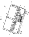
- FIG. 10 and 11 are perspective views according to Modification 3 and Modification 4 of the battery pack shown in FIG. 5, respectively.
- the length of the heat dissipation member 40 in the vertical direction (Y direction) of the housing 10 is shorter than the length of the battery pack 100 according to the above-described embodiment.
- the heat dissipation member 40 is not fixed to the connecting portion 24 of the battery module 20, but the bottom wall 10b of the housing 10 is interposed via the flange portion 42 as a fixing member. It is fixed to.
Landscapes
- Chemical & Material Sciences (AREA)
- Chemical Kinetics & Catalysis (AREA)
- Electrochemistry (AREA)
- General Chemical & Material Sciences (AREA)
- Physics & Mathematics (AREA)
- Thermal Sciences (AREA)
- Engineering & Computer Science (AREA)
- Microelectronics & Electronic Packaging (AREA)
- Electromagnetism (AREA)
- Battery Mounting, Suspending (AREA)
- Cooling Or The Like Of Electrical Apparatus (AREA)
- Secondary Cells (AREA)
Abstract
L'invention concerne un bloc-batterie qui peut dissiper la chaleur qui a été générée au niveau d'un relais vers un boîtier par conduction thermique et peut supprimer un échauffement local du boîtier. Le bloc-batterie 100 comprend un boîtier 10, une pluralité d'éléments de batterie qui sont logés dans le boîtier 10, et un relais 32 qui est connecté à la pluralité d'éléments de batterie. Le bloc-batterie 100 comprend également un élément de dissipation de chaleur 40 qui conduit et ainsi dissipe la chaleur qui a été générée au niveau du relais 32. L'élément de dissipation de chaleur 40 forme un chemin de conduction thermique Pt qui est plus long que la plus courte distance Ds entre le relais 32 et le boîtier 10.
Priority Applications (1)
| Application Number | Priority Date | Filing Date | Title |
|---|---|---|---|
| JP2020565628A JP7078757B2 (ja) | 2019-01-10 | 2019-12-05 | 電池パック |
Applications Claiming Priority (2)
| Application Number | Priority Date | Filing Date | Title |
|---|---|---|---|
| JP2019-002544 | 2019-01-10 | ||
| JP2019002544 | 2019-01-10 |
Publications (1)
| Publication Number | Publication Date |
|---|---|
| WO2020144985A1 true WO2020144985A1 (fr) | 2020-07-16 |
Family
ID=71520806
Family Applications (1)
| Application Number | Title | Priority Date | Filing Date |
|---|---|---|---|
| PCT/JP2019/047686 Ceased WO2020144985A1 (fr) | 2019-01-10 | 2019-12-05 | Bloc-batterie |
Country Status (2)
| Country | Link |
|---|---|
| JP (1) | JP7078757B2 (fr) |
| WO (1) | WO2020144985A1 (fr) |
Cited By (3)
| Publication number | Priority date | Publication date | Assignee | Title |
|---|---|---|---|---|
| JP2023554204A (ja) * | 2021-11-22 | 2023-12-27 | 寧徳時代新能源科技股▲分▼有限公司 | 高圧ボックス、電池および電気設備 |
| EP4730383A1 (fr) * | 2024-10-17 | 2026-04-22 | Samsung Sdi Co., Ltd. | Dispositif de déconnexion de batterie et bloc-batterie |
| US12620648B2 (en) | 2021-11-22 | 2026-05-05 | Contemporary Amperex Technology (Hong Kong) Limited | High voltage box, battery and electric device |
Citations (3)
| Publication number | Priority date | Publication date | Assignee | Title |
|---|---|---|---|---|
| JPH1098288A (ja) * | 1996-09-24 | 1998-04-14 | Canon Inc | 電子機器ケース、放熱板、及び電子機器 |
| WO2014068880A1 (fr) * | 2012-10-29 | 2014-05-08 | 三洋電機株式会社 | Dispositif d'alimentation électrique et véhicule comportant le dispositif d'alimentation électrique |
| JP2018063921A (ja) * | 2016-10-14 | 2018-04-19 | 株式会社デンソー | 電池装置 |
Family Cites Families (3)
| Publication number | Priority date | Publication date | Assignee | Title |
|---|---|---|---|---|
| JP2002223089A (ja) * | 2001-01-26 | 2002-08-09 | Toshiba Lighting & Technology Corp | 電気機器および放電灯点灯装置 |
| JP6081128B2 (ja) * | 2012-10-10 | 2017-02-15 | 三洋電機株式会社 | 電源装置及びこれを備える車両並びに蓄電装置 |
| JP6642088B2 (ja) * | 2016-02-18 | 2020-02-05 | 株式会社オートネットワーク技術研究所 | 電気機器 |
-
2019
- 2019-12-05 JP JP2020565628A patent/JP7078757B2/ja active Active
- 2019-12-05 WO PCT/JP2019/047686 patent/WO2020144985A1/fr not_active Ceased
Patent Citations (3)
| Publication number | Priority date | Publication date | Assignee | Title |
|---|---|---|---|---|
| JPH1098288A (ja) * | 1996-09-24 | 1998-04-14 | Canon Inc | 電子機器ケース、放熱板、及び電子機器 |
| WO2014068880A1 (fr) * | 2012-10-29 | 2014-05-08 | 三洋電機株式会社 | Dispositif d'alimentation électrique et véhicule comportant le dispositif d'alimentation électrique |
| JP2018063921A (ja) * | 2016-10-14 | 2018-04-19 | 株式会社デンソー | 電池装置 |
Cited By (4)
| Publication number | Priority date | Publication date | Assignee | Title |
|---|---|---|---|---|
| JP2023554204A (ja) * | 2021-11-22 | 2023-12-27 | 寧徳時代新能源科技股▲分▼有限公司 | 高圧ボックス、電池および電気設備 |
| JP7510511B2 (ja) | 2021-11-22 | 2024-07-03 | 寧徳時代新能源科技股▲分▼有限公司 | 高圧ボックス、電池および電気設備 |
| US12620648B2 (en) | 2021-11-22 | 2026-05-05 | Contemporary Amperex Technology (Hong Kong) Limited | High voltage box, battery and electric device |
| EP4730383A1 (fr) * | 2024-10-17 | 2026-04-22 | Samsung Sdi Co., Ltd. | Dispositif de déconnexion de batterie et bloc-batterie |
Also Published As
| Publication number | Publication date |
|---|---|
| JPWO2020144985A1 (ja) | 2021-12-09 |
| JP7078757B2 (ja) | 2022-05-31 |
Similar Documents
| Publication | Publication Date | Title |
|---|---|---|
| CN103069284B (zh) | 电压感测组件和采用电压感测组件的电池模块 | |
| CN104064699B (zh) | 蓄电装置 | |
| CN107644960A (zh) | 电池系统 | |
| CN103081175A (zh) | 电池模块和采用该电池模块的电池组 | |
| JP2011175743A (ja) | 電源装置及びこれを備える車両 | |
| CN111630682B (zh) | 电池包 | |
| CN103081214A (zh) | 具有紧凑结构的电池组 | |
| US12068467B2 (en) | Battery pack and device including the same | |
| WO2020066060A1 (fr) | Bloc batterie | |
| JPWO2015162841A1 (ja) | 電池ブロック | |
| JP7475480B2 (ja) | 電池モジュールおよびこれを含む電池パック | |
| EP4160783B1 (fr) | Bloc-batterie | |
| JP2018133152A (ja) | 電池モジュール及び電池パック | |
| JP6720847B2 (ja) | 電池パック | |
| CN208127265U (zh) | 电池包 | |
| WO2018062226A1 (fr) | Module de batterie et bloc-batterie | |
| JP7078757B2 (ja) | 電池パック | |
| WO2020075507A1 (fr) | Batterie | |
| JP2013105723A (ja) | 蓄電装置 | |
| JP5738714B2 (ja) | 組電池 | |
| US20250030130A1 (en) | Battery pack for an electric-powered road vehicle and electric-powered road vehicle equipped with such a battery pack | |
| JP7023359B2 (ja) | 電池パック | |
| KR20240003775A (ko) | 열폭주 안정성을 갖는 배터리 시스템 | |
| JP7166486B2 (ja) | 電池モジュール及び電池システム | |
| WO2023079695A1 (fr) | Module de batterie et système de stockage d'énergie |
Legal Events
| Date | Code | Title | Description |
|---|---|---|---|
| 121 | Ep: the epo has been informed by wipo that ep was designated in this application |
Ref document number: 19908092 Country of ref document: EP Kind code of ref document: A1 |
|
| ENP | Entry into the national phase |
Ref document number: 2020565628 Country of ref document: JP Kind code of ref document: A |
|
| NENP | Non-entry into the national phase |
Ref country code: DE |
|
| 122 | Ep: pct application non-entry in european phase |
Ref document number: 19908092 Country of ref document: EP Kind code of ref document: A1 |