WO2020145314A1 - 方向性電磁鋼板、焼鈍分離剤、及び方向性電磁鋼板の製造方法 - Google Patents
方向性電磁鋼板、焼鈍分離剤、及び方向性電磁鋼板の製造方法 Download PDFInfo
- Publication number
- WO2020145314A1 WO2020145314A1 PCT/JP2020/000338 JP2020000338W WO2020145314A1 WO 2020145314 A1 WO2020145314 A1 WO 2020145314A1 JP 2020000338 W JP2020000338 W JP 2020000338W WO 2020145314 A1 WO2020145314 A1 WO 2020145314A1
- Authority
- WO
- WIPO (PCT)
- Prior art keywords
- steel sheet
- primary coating
- group
- grain
- region
- Prior art date
- Legal status (The legal status is an assumption and is not a legal conclusion. Google has not performed a legal analysis and makes no representation as to the accuracy of the status listed.)
- Ceased
Links
Images


Classifications
-
- C—CHEMISTRY; METALLURGY
- C21—METALLURGY OF IRON
- C21D—MODIFYING THE PHYSICAL STRUCTURE OF FERROUS METALS; GENERAL DEVICES FOR HEAT TREATMENT OF FERROUS OR NON-FERROUS METALS OR ALLOYS; MAKING METAL MALLEABLE, e.g. BY DECARBURISATION OR TEMPERING
- C21D9/00—Heat treatment, e.g. annealing, hardening, quenching or tempering, adapted for particular articles; Furnaces therefor
- C21D9/46—Heat treatment, e.g. annealing, hardening, quenching or tempering, adapted for particular articles; Furnaces therefor for sheet metals
-
- H—ELECTRICITY
- H01—ELECTRIC ELEMENTS
- H01F—MAGNETS; INDUCTANCES; TRANSFORMERS; SELECTION OF MATERIALS FOR THEIR MAGNETIC PROPERTIES
- H01F1/00—Magnets or magnetic bodies characterised by the magnetic materials therefor; Selection of materials for their magnetic properties
- H01F1/01—Magnets or magnetic bodies characterised by the magnetic materials therefor; Selection of materials for their magnetic properties of inorganic materials
- H01F1/03—Magnets or magnetic bodies characterised by the magnetic materials therefor; Selection of materials for their magnetic properties of inorganic materials characterised by their coercivity
- H01F1/12—Magnets or magnetic bodies characterised by the magnetic materials therefor; Selection of materials for their magnetic properties of inorganic materials characterised by their coercivity of soft-magnetic materials
- H01F1/14—Magnets or magnetic bodies characterised by the magnetic materials therefor; Selection of materials for their magnetic properties of inorganic materials characterised by their coercivity of soft-magnetic materials metals or alloys
- H01F1/147—Alloys characterised by their composition
- H01F1/14766—Fe-Si based alloys
- H01F1/14775—Fe-Si based alloys in the form of sheets
- H01F1/14783—Fe-Si based alloys in the form of sheets with insulating coating
-
- C—CHEMISTRY; METALLURGY
- C04—CEMENTS; CONCRETE; ARTIFICIAL STONE; CERAMICS; REFRACTORIES
- C04B—LIME, MAGNESIA; SLAG; CEMENTS; COMPOSITIONS THEREOF, e.g. MORTARS, CONCRETE OR LIKE BUILDING MATERIALS; ARTIFICIAL STONE; CERAMICS; REFRACTORIES; TREATMENT OF NATURAL STONE
- C04B35/00—Shaped ceramic products characterised by their composition; Ceramics compositions; Processing powders of inorganic compounds preparatory to the manufacturing of ceramic products
- C04B35/01—Shaped ceramic products characterised by their composition; Ceramics compositions; Processing powders of inorganic compounds preparatory to the manufacturing of ceramic products based on oxide ceramics
- C04B35/03—Shaped ceramic products characterised by their composition; Ceramics compositions; Processing powders of inorganic compounds preparatory to the manufacturing of ceramic products based on oxide ceramics based on magnesium oxide, calcium oxide or oxide mixtures derived from dolomite
- C04B35/04—Shaped ceramic products characterised by their composition; Ceramics compositions; Processing powders of inorganic compounds preparatory to the manufacturing of ceramic products based on oxide ceramics based on magnesium oxide, calcium oxide or oxide mixtures derived from dolomite based on magnesium oxide
- C04B35/053—Fine ceramics
-
- C—CHEMISTRY; METALLURGY
- C21—METALLURGY OF IRON
- C21D—MODIFYING THE PHYSICAL STRUCTURE OF FERROUS METALS; GENERAL DEVICES FOR HEAT TREATMENT OF FERROUS OR NON-FERROUS METALS OR ALLOYS; MAKING METAL MALLEABLE, e.g. BY DECARBURISATION OR TEMPERING
- C21D3/00—Diffusion processes for extraction of non-metals; Furnaces therefor
- C21D3/02—Extraction of non-metals
- C21D3/04—Decarburising
-
- C—CHEMISTRY; METALLURGY
- C21—METALLURGY OF IRON
- C21D—MODIFYING THE PHYSICAL STRUCTURE OF FERROUS METALS; GENERAL DEVICES FOR HEAT TREATMENT OF FERROUS OR NON-FERROUS METALS OR ALLOYS; MAKING METAL MALLEABLE, e.g. BY DECARBURISATION OR TEMPERING
- C21D6/00—Heat treatment of ferrous alloys
- C21D6/005—Heat treatment of ferrous alloys containing Mn
-
- C—CHEMISTRY; METALLURGY
- C21—METALLURGY OF IRON
- C21D—MODIFYING THE PHYSICAL STRUCTURE OF FERROUS METALS; GENERAL DEVICES FOR HEAT TREATMENT OF FERROUS OR NON-FERROUS METALS OR ALLOYS; MAKING METAL MALLEABLE, e.g. BY DECARBURISATION OR TEMPERING
- C21D6/00—Heat treatment of ferrous alloys
- C21D6/008—Heat treatment of ferrous alloys containing Si
-
- C—CHEMISTRY; METALLURGY
- C21—METALLURGY OF IRON
- C21D—MODIFYING THE PHYSICAL STRUCTURE OF FERROUS METALS; GENERAL DEVICES FOR HEAT TREATMENT OF FERROUS OR NON-FERROUS METALS OR ALLOYS; MAKING METAL MALLEABLE, e.g. BY DECARBURISATION OR TEMPERING
- C21D8/00—Modifying the physical properties of ferrous metals or ferrous alloys by deformation combined with, or followed by, heat treatment
- C21D8/12—Modifying the physical properties of ferrous metals or ferrous alloys by deformation combined with, or followed by, heat treatment during manufacturing of articles with special electromagnetic properties
- C21D8/1216—Modifying the physical properties of ferrous metals or ferrous alloys by deformation combined with, or followed by, heat treatment during manufacturing of articles with special electromagnetic properties characterised by the working steps
- C21D8/1222—Hot rolling
-
- C—CHEMISTRY; METALLURGY
- C21—METALLURGY OF IRON
- C21D—MODIFYING THE PHYSICAL STRUCTURE OF FERROUS METALS; GENERAL DEVICES FOR HEAT TREATMENT OF FERROUS OR NON-FERROUS METALS OR ALLOYS; MAKING METAL MALLEABLE, e.g. BY DECARBURISATION OR TEMPERING
- C21D8/00—Modifying the physical properties of ferrous metals or ferrous alloys by deformation combined with, or followed by, heat treatment
- C21D8/12—Modifying the physical properties of ferrous metals or ferrous alloys by deformation combined with, or followed by, heat treatment during manufacturing of articles with special electromagnetic properties
- C21D8/1216—Modifying the physical properties of ferrous metals or ferrous alloys by deformation combined with, or followed by, heat treatment during manufacturing of articles with special electromagnetic properties characterised by the working steps
- C21D8/1233—Cold rolling
-
- C—CHEMISTRY; METALLURGY
- C21—METALLURGY OF IRON
- C21D—MODIFYING THE PHYSICAL STRUCTURE OF FERROUS METALS; GENERAL DEVICES FOR HEAT TREATMENT OF FERROUS OR NON-FERROUS METALS OR ALLOYS; MAKING METAL MALLEABLE, e.g. BY DECARBURISATION OR TEMPERING
- C21D8/00—Modifying the physical properties of ferrous metals or ferrous alloys by deformation combined with, or followed by, heat treatment
- C21D8/12—Modifying the physical properties of ferrous metals or ferrous alloys by deformation combined with, or followed by, heat treatment during manufacturing of articles with special electromagnetic properties
- C21D8/1244—Modifying the physical properties of ferrous metals or ferrous alloys by deformation combined with, or followed by, heat treatment during manufacturing of articles with special electromagnetic properties characterised by the heat treatment
- C21D8/1272—Final recrystallisation annealing
-
- C—CHEMISTRY; METALLURGY
- C21—METALLURGY OF IRON
- C21D—MODIFYING THE PHYSICAL STRUCTURE OF FERROUS METALS; GENERAL DEVICES FOR HEAT TREATMENT OF FERROUS OR NON-FERROUS METALS OR ALLOYS; MAKING METAL MALLEABLE, e.g. BY DECARBURISATION OR TEMPERING
- C21D8/00—Modifying the physical properties of ferrous metals or ferrous alloys by deformation combined with, or followed by, heat treatment
- C21D8/12—Modifying the physical properties of ferrous metals or ferrous alloys by deformation combined with, or followed by, heat treatment during manufacturing of articles with special electromagnetic properties
- C21D8/1277—Modifying the physical properties of ferrous metals or ferrous alloys by deformation combined with, or followed by, heat treatment during manufacturing of articles with special electromagnetic properties involving a particular surface treatment
- C21D8/1283—Application of a separating or insulating coating
-
- C—CHEMISTRY; METALLURGY
- C22—METALLURGY; FERROUS OR NON-FERROUS ALLOYS; TREATMENT OF ALLOYS OR NON-FERROUS METALS
- C22C—ALLOYS
- C22C38/00—Ferrous alloys, e.g. steel alloys
- C22C38/001—Ferrous alloys, e.g. steel alloys containing N
-
- C—CHEMISTRY; METALLURGY
- C22—METALLURGY; FERROUS OR NON-FERROUS ALLOYS; TREATMENT OF ALLOYS OR NON-FERROUS METALS
- C22C—ALLOYS
- C22C38/00—Ferrous alloys, e.g. steel alloys
- C22C38/002—Ferrous alloys, e.g. steel alloys containing In, Mg, or other elements not provided for in one single group C22C38/001 - C22C38/60
-
- C—CHEMISTRY; METALLURGY
- C22—METALLURGY; FERROUS OR NON-FERROUS ALLOYS; TREATMENT OF ALLOYS OR NON-FERROUS METALS
- C22C—ALLOYS
- C22C38/00—Ferrous alloys, e.g. steel alloys
- C22C38/004—Very low carbon steels, i.e. having a carbon content of less than 0,01%
-
- C—CHEMISTRY; METALLURGY
- C22—METALLURGY; FERROUS OR NON-FERROUS ALLOYS; TREATMENT OF ALLOYS OR NON-FERROUS METALS
- C22C—ALLOYS
- C22C38/00—Ferrous alloys, e.g. steel alloys
- C22C38/008—Ferrous alloys, e.g. steel alloys containing tin
-
- C—CHEMISTRY; METALLURGY
- C22—METALLURGY; FERROUS OR NON-FERROUS ALLOYS; TREATMENT OF ALLOYS OR NON-FERROUS METALS
- C22C—ALLOYS
- C22C38/00—Ferrous alloys, e.g. steel alloys
- C22C38/02—Ferrous alloys, e.g. steel alloys containing silicon
-
- C—CHEMISTRY; METALLURGY
- C22—METALLURGY; FERROUS OR NON-FERROUS ALLOYS; TREATMENT OF ALLOYS OR NON-FERROUS METALS
- C22C—ALLOYS
- C22C38/00—Ferrous alloys, e.g. steel alloys
- C22C38/04—Ferrous alloys, e.g. steel alloys containing manganese
-
- C—CHEMISTRY; METALLURGY
- C22—METALLURGY; FERROUS OR NON-FERROUS ALLOYS; TREATMENT OF ALLOYS OR NON-FERROUS METALS
- C22C—ALLOYS
- C22C38/00—Ferrous alloys, e.g. steel alloys
- C22C38/06—Ferrous alloys, e.g. steel alloys containing aluminium
-
- C—CHEMISTRY; METALLURGY
- C22—METALLURGY; FERROUS OR NON-FERROUS ALLOYS; TREATMENT OF ALLOYS OR NON-FERROUS METALS
- C22C—ALLOYS
- C22C38/00—Ferrous alloys, e.g. steel alloys
- C22C38/16—Ferrous alloys, e.g. steel alloys containing copper
-
- C—CHEMISTRY; METALLURGY
- C22—METALLURGY; FERROUS OR NON-FERROUS ALLOYS; TREATMENT OF ALLOYS OR NON-FERROUS METALS
- C22C—ALLOYS
- C22C38/00—Ferrous alloys, e.g. steel alloys
- C22C38/60—Ferrous alloys, e.g. steel alloys containing lead, selenium, tellurium, or antimony, or more than 0.04% by weight of sulfur
-
- C—CHEMISTRY; METALLURGY
- C23—COATING METALLIC MATERIAL; COATING MATERIAL WITH METALLIC MATERIAL; CHEMICAL SURFACE TREATMENT; DIFFUSION TREATMENT OF METALLIC MATERIAL; COATING BY VACUUM EVAPORATION, BY SPUTTERING, BY ION IMPLANTATION OR BY CHEMICAL VAPOUR DEPOSITION, IN GENERAL; INHIBITING CORROSION OF METALLIC MATERIAL OR INCRUSTATION IN GENERAL
- C23C—COATING METALLIC MATERIAL; COATING MATERIAL WITH METALLIC MATERIAL; SURFACE TREATMENT OF METALLIC MATERIAL BY DIFFUSION INTO THE SURFACE, BY CHEMICAL CONVERSION OR SUBSTITUTION; COATING BY VACUUM EVAPORATION, BY SPUTTERING, BY ION IMPLANTATION OR BY CHEMICAL VAPOUR DEPOSITION, IN GENERAL
- C23C22/00—Chemical surface treatment of metallic material by reaction of the surface with a reactive liquid, leaving reaction products of surface material in the coating, e.g. conversion coatings, passivation of metals
- C23C22/05—Chemical surface treatment of metallic material by reaction of the surface with a reactive liquid, leaving reaction products of surface material in the coating, e.g. conversion coatings, passivation of metals using aqueous solutions
- C23C22/06—Chemical surface treatment of metallic material by reaction of the surface with a reactive liquid, leaving reaction products of surface material in the coating, e.g. conversion coatings, passivation of metals using aqueous solutions using aqueous acidic solutions with pH less than 6
- C23C22/48—Chemical surface treatment of metallic material by reaction of the surface with a reactive liquid, leaving reaction products of surface material in the coating, e.g. conversion coatings, passivation of metals using aqueous solutions using aqueous acidic solutions with pH less than 6 not containing phosphates, hexavalent chromium compounds, fluorides or complex fluorides, molybdates, tungstates, vanadates or oxalates
- C23C22/57—Treatment of magnesium or alloys based thereon
-
- C—CHEMISTRY; METALLURGY
- C23—COATING METALLIC MATERIAL; COATING MATERIAL WITH METALLIC MATERIAL; CHEMICAL SURFACE TREATMENT; DIFFUSION TREATMENT OF METALLIC MATERIAL; COATING BY VACUUM EVAPORATION, BY SPUTTERING, BY ION IMPLANTATION OR BY CHEMICAL VAPOUR DEPOSITION, IN GENERAL; INHIBITING CORROSION OF METALLIC MATERIAL OR INCRUSTATION IN GENERAL
- C23C—COATING METALLIC MATERIAL; COATING MATERIAL WITH METALLIC MATERIAL; SURFACE TREATMENT OF METALLIC MATERIAL BY DIFFUSION INTO THE SURFACE, BY CHEMICAL CONVERSION OR SUBSTITUTION; COATING BY VACUUM EVAPORATION, BY SPUTTERING, BY ION IMPLANTATION OR BY CHEMICAL VAPOUR DEPOSITION, IN GENERAL
- C23C24/00—Coating starting from inorganic powder
- C23C24/02—Coating starting from inorganic powder by application of pressure only
- C23C24/04—Impact or kinetic deposition of particles
-
- C—CHEMISTRY; METALLURGY
- C23—COATING METALLIC MATERIAL; COATING MATERIAL WITH METALLIC MATERIAL; CHEMICAL SURFACE TREATMENT; DIFFUSION TREATMENT OF METALLIC MATERIAL; COATING BY VACUUM EVAPORATION, BY SPUTTERING, BY ION IMPLANTATION OR BY CHEMICAL VAPOUR DEPOSITION, IN GENERAL; INHIBITING CORROSION OF METALLIC MATERIAL OR INCRUSTATION IN GENERAL
- C23C—COATING METALLIC MATERIAL; COATING MATERIAL WITH METALLIC MATERIAL; SURFACE TREATMENT OF METALLIC MATERIAL BY DIFFUSION INTO THE SURFACE, BY CHEMICAL CONVERSION OR SUBSTITUTION; COATING BY VACUUM EVAPORATION, BY SPUTTERING, BY ION IMPLANTATION OR BY CHEMICAL VAPOUR DEPOSITION, IN GENERAL
- C23C24/00—Coating starting from inorganic powder
- C23C24/08—Coating starting from inorganic powder by application of heat or pressure and heat
-
- C—CHEMISTRY; METALLURGY
- C23—COATING METALLIC MATERIAL; COATING MATERIAL WITH METALLIC MATERIAL; CHEMICAL SURFACE TREATMENT; DIFFUSION TREATMENT OF METALLIC MATERIAL; COATING BY VACUUM EVAPORATION, BY SPUTTERING, BY ION IMPLANTATION OR BY CHEMICAL VAPOUR DEPOSITION, IN GENERAL; INHIBITING CORROSION OF METALLIC MATERIAL OR INCRUSTATION IN GENERAL
- C23C—COATING METALLIC MATERIAL; COATING MATERIAL WITH METALLIC MATERIAL; SURFACE TREATMENT OF METALLIC MATERIAL BY DIFFUSION INTO THE SURFACE, BY CHEMICAL CONVERSION OR SUBSTITUTION; COATING BY VACUUM EVAPORATION, BY SPUTTERING, BY ION IMPLANTATION OR BY CHEMICAL VAPOUR DEPOSITION, IN GENERAL
- C23C26/00—Coating not provided for in groups C23C2/00 - C23C24/00
-
- H—ELECTRICITY
- H01—ELECTRIC ELEMENTS
- H01F—MAGNETS; INDUCTANCES; TRANSFORMERS; SELECTION OF MATERIALS FOR THEIR MAGNETIC PROPERTIES
- H01F1/00—Magnets or magnetic bodies characterised by the magnetic materials therefor; Selection of materials for their magnetic properties
- H01F1/01—Magnets or magnetic bodies characterised by the magnetic materials therefor; Selection of materials for their magnetic properties of inorganic materials
- H01F1/03—Magnets or magnetic bodies characterised by the magnetic materials therefor; Selection of materials for their magnetic properties of inorganic materials characterised by their coercivity
- H01F1/12—Magnets or magnetic bodies characterised by the magnetic materials therefor; Selection of materials for their magnetic properties of inorganic materials characterised by their coercivity of soft-magnetic materials
- H01F1/14—Magnets or magnetic bodies characterised by the magnetic materials therefor; Selection of materials for their magnetic properties of inorganic materials characterised by their coercivity of soft-magnetic materials metals or alloys
- H01F1/147—Alloys characterised by their composition
- H01F1/14766—Fe-Si based alloys
-
- C—CHEMISTRY; METALLURGY
- C04—CEMENTS; CONCRETE; ARTIFICIAL STONE; CERAMICS; REFRACTORIES
- C04B—LIME, MAGNESIA; SLAG; CEMENTS; COMPOSITIONS THEREOF, e.g. MORTARS, CONCRETE OR LIKE BUILDING MATERIALS; ARTIFICIAL STONE; CERAMICS; REFRACTORIES; TREATMENT OF NATURAL STONE
- C04B2235/00—Aspects relating to ceramic starting mixtures or sintered ceramic products
- C04B2235/02—Composition of constituents of the starting material or of secondary phases of the final product
- C04B2235/30—Constituents and secondary phases not being of a fibrous nature
- C04B2235/32—Metal oxides, mixed metal oxides, or oxide-forming salts thereof, e.g. carbonates, nitrates, (oxy)hydroxides, chlorides
- C04B2235/3205—Alkaline earth oxides or oxide forming salts thereof, e.g. beryllium oxide
- C04B2235/3208—Calcium oxide or oxide-forming salts thereof, e.g. lime
-
- C—CHEMISTRY; METALLURGY
- C04—CEMENTS; CONCRETE; ARTIFICIAL STONE; CERAMICS; REFRACTORIES
- C04B—LIME, MAGNESIA; SLAG; CEMENTS; COMPOSITIONS THEREOF, e.g. MORTARS, CONCRETE OR LIKE BUILDING MATERIALS; ARTIFICIAL STONE; CERAMICS; REFRACTORIES; TREATMENT OF NATURAL STONE
- C04B2235/00—Aspects relating to ceramic starting mixtures or sintered ceramic products
- C04B2235/02—Composition of constituents of the starting material or of secondary phases of the final product
- C04B2235/30—Constituents and secondary phases not being of a fibrous nature
- C04B2235/32—Metal oxides, mixed metal oxides, or oxide-forming salts thereof, e.g. carbonates, nitrates, (oxy)hydroxides, chlorides
- C04B2235/3205—Alkaline earth oxides or oxide forming salts thereof, e.g. beryllium oxide
- C04B2235/3213—Strontium oxides or oxide-forming salts thereof
-
- C—CHEMISTRY; METALLURGY
- C04—CEMENTS; CONCRETE; ARTIFICIAL STONE; CERAMICS; REFRACTORIES
- C04B—LIME, MAGNESIA; SLAG; CEMENTS; COMPOSITIONS THEREOF, e.g. MORTARS, CONCRETE OR LIKE BUILDING MATERIALS; ARTIFICIAL STONE; CERAMICS; REFRACTORIES; TREATMENT OF NATURAL STONE
- C04B2235/00—Aspects relating to ceramic starting mixtures or sintered ceramic products
- C04B2235/02—Composition of constituents of the starting material or of secondary phases of the final product
- C04B2235/30—Constituents and secondary phases not being of a fibrous nature
- C04B2235/32—Metal oxides, mixed metal oxides, or oxide-forming salts thereof, e.g. carbonates, nitrates, (oxy)hydroxides, chlorides
- C04B2235/3205—Alkaline earth oxides or oxide forming salts thereof, e.g. beryllium oxide
- C04B2235/3215—Barium oxides or oxide-forming salts thereof
-
- C—CHEMISTRY; METALLURGY
- C04—CEMENTS; CONCRETE; ARTIFICIAL STONE; CERAMICS; REFRACTORIES
- C04B—LIME, MAGNESIA; SLAG; CEMENTS; COMPOSITIONS THEREOF, e.g. MORTARS, CONCRETE OR LIKE BUILDING MATERIALS; ARTIFICIAL STONE; CERAMICS; REFRACTORIES; TREATMENT OF NATURAL STONE
- C04B2235/00—Aspects relating to ceramic starting mixtures or sintered ceramic products
- C04B2235/02—Composition of constituents of the starting material or of secondary phases of the final product
- C04B2235/30—Constituents and secondary phases not being of a fibrous nature
- C04B2235/32—Metal oxides, mixed metal oxides, or oxide-forming salts thereof, e.g. carbonates, nitrates, (oxy)hydroxides, chlorides
- C04B2235/3224—Rare earth oxide or oxide forming salts thereof, e.g. scandium oxide
- C04B2235/3225—Yttrium oxide or oxide-forming salts thereof
-
- C—CHEMISTRY; METALLURGY
- C04—CEMENTS; CONCRETE; ARTIFICIAL STONE; CERAMICS; REFRACTORIES
- C04B—LIME, MAGNESIA; SLAG; CEMENTS; COMPOSITIONS THEREOF, e.g. MORTARS, CONCRETE OR LIKE BUILDING MATERIALS; ARTIFICIAL STONE; CERAMICS; REFRACTORIES; TREATMENT OF NATURAL STONE
- C04B2235/00—Aspects relating to ceramic starting mixtures or sintered ceramic products
- C04B2235/02—Composition of constituents of the starting material or of secondary phases of the final product
- C04B2235/30—Constituents and secondary phases not being of a fibrous nature
- C04B2235/32—Metal oxides, mixed metal oxides, or oxide-forming salts thereof, e.g. carbonates, nitrates, (oxy)hydroxides, chlorides
- C04B2235/3224—Rare earth oxide or oxide forming salts thereof, e.g. scandium oxide
- C04B2235/3227—Lanthanum oxide or oxide-forming salts thereof
-
- C—CHEMISTRY; METALLURGY
- C04—CEMENTS; CONCRETE; ARTIFICIAL STONE; CERAMICS; REFRACTORIES
- C04B—LIME, MAGNESIA; SLAG; CEMENTS; COMPOSITIONS THEREOF, e.g. MORTARS, CONCRETE OR LIKE BUILDING MATERIALS; ARTIFICIAL STONE; CERAMICS; REFRACTORIES; TREATMENT OF NATURAL STONE
- C04B2235/00—Aspects relating to ceramic starting mixtures or sintered ceramic products
- C04B2235/02—Composition of constituents of the starting material or of secondary phases of the final product
- C04B2235/30—Constituents and secondary phases not being of a fibrous nature
- C04B2235/32—Metal oxides, mixed metal oxides, or oxide-forming salts thereof, e.g. carbonates, nitrates, (oxy)hydroxides, chlorides
- C04B2235/3224—Rare earth oxide or oxide forming salts thereof, e.g. scandium oxide
- C04B2235/3229—Cerium oxides or oxide-forming salts thereof
-
- C—CHEMISTRY; METALLURGY
- C04—CEMENTS; CONCRETE; ARTIFICIAL STONE; CERAMICS; REFRACTORIES
- C04B—LIME, MAGNESIA; SLAG; CEMENTS; COMPOSITIONS THEREOF, e.g. MORTARS, CONCRETE OR LIKE BUILDING MATERIALS; ARTIFICIAL STONE; CERAMICS; REFRACTORIES; TREATMENT OF NATURAL STONE
- C04B2235/00—Aspects relating to ceramic starting mixtures or sintered ceramic products
- C04B2235/02—Composition of constituents of the starting material or of secondary phases of the final product
- C04B2235/30—Constituents and secondary phases not being of a fibrous nature
- C04B2235/32—Metal oxides, mixed metal oxides, or oxide-forming salts thereof, e.g. carbonates, nitrates, (oxy)hydroxides, chlorides
- C04B2235/3231—Refractory metal oxides, their mixed metal oxides, or oxide-forming salts thereof
- C04B2235/3232—Titanium oxides or titanates, e.g. rutile or anatase
-
- C—CHEMISTRY; METALLURGY
- C04—CEMENTS; CONCRETE; ARTIFICIAL STONE; CERAMICS; REFRACTORIES
- C04B—LIME, MAGNESIA; SLAG; CEMENTS; COMPOSITIONS THEREOF, e.g. MORTARS, CONCRETE OR LIKE BUILDING MATERIALS; ARTIFICIAL STONE; CERAMICS; REFRACTORIES; TREATMENT OF NATURAL STONE
- C04B2235/00—Aspects relating to ceramic starting mixtures or sintered ceramic products
- C04B2235/02—Composition of constituents of the starting material or of secondary phases of the final product
- C04B2235/30—Constituents and secondary phases not being of a fibrous nature
- C04B2235/32—Metal oxides, mixed metal oxides, or oxide-forming salts thereof, e.g. carbonates, nitrates, (oxy)hydroxides, chlorides
- C04B2235/3231—Refractory metal oxides, their mixed metal oxides, or oxide-forming salts thereof
- C04B2235/3244—Zirconium oxides, zirconates, hafnium oxides, hafnates, or oxide-forming salts thereof
-
- C—CHEMISTRY; METALLURGY
- C04—CEMENTS; CONCRETE; ARTIFICIAL STONE; CERAMICS; REFRACTORIES
- C04B—LIME, MAGNESIA; SLAG; CEMENTS; COMPOSITIONS THEREOF, e.g. MORTARS, CONCRETE OR LIKE BUILDING MATERIALS; ARTIFICIAL STONE; CERAMICS; REFRACTORIES; TREATMENT OF NATURAL STONE
- C04B2235/00—Aspects relating to ceramic starting mixtures or sintered ceramic products
- C04B2235/02—Composition of constituents of the starting material or of secondary phases of the final product
- C04B2235/30—Constituents and secondary phases not being of a fibrous nature
- C04B2235/44—Metal salt constituents or additives chosen for the nature of the anions, e.g. hydrides or acetylacetonate
- C04B2235/448—Sulphates or sulphites
-
- C—CHEMISTRY; METALLURGY
- C04—CEMENTS; CONCRETE; ARTIFICIAL STONE; CERAMICS; REFRACTORIES
- C04B—LIME, MAGNESIA; SLAG; CEMENTS; COMPOSITIONS THEREOF, e.g. MORTARS, CONCRETE OR LIKE BUILDING MATERIALS; ARTIFICIAL STONE; CERAMICS; REFRACTORIES; TREATMENT OF NATURAL STONE
- C04B2235/00—Aspects relating to ceramic starting mixtures or sintered ceramic products
- C04B2235/02—Composition of constituents of the starting material or of secondary phases of the final product
- C04B2235/50—Constituents or additives of the starting mixture chosen for their shape or used because of their shape or their physical appearance
- C04B2235/54—Particle size related information
- C04B2235/5418—Particle size related information expressed by the size of the particles or aggregates thereof
- C04B2235/5436—Particle size related information expressed by the size of the particles or aggregates thereof micrometer sized, i.e. from 1 to 100 micron
-
- C—CHEMISTRY; METALLURGY
- C04—CEMENTS; CONCRETE; ARTIFICIAL STONE; CERAMICS; REFRACTORIES
- C04B—LIME, MAGNESIA; SLAG; CEMENTS; COMPOSITIONS THEREOF, e.g. MORTARS, CONCRETE OR LIKE BUILDING MATERIALS; ARTIFICIAL STONE; CERAMICS; REFRACTORIES; TREATMENT OF NATURAL STONE
- C04B2235/00—Aspects relating to ceramic starting mixtures or sintered ceramic products
- C04B2235/02—Composition of constituents of the starting material or of secondary phases of the final product
- C04B2235/50—Constituents or additives of the starting mixture chosen for their shape or used because of their shape or their physical appearance
- C04B2235/54—Particle size related information
- C04B2235/5418—Particle size related information expressed by the size of the particles or aggregates thereof
- C04B2235/5445—Particle size related information expressed by the size of the particles or aggregates thereof submicron sized, i.e. from 0,1 to 1 micron
-
- Y—GENERAL TAGGING OF NEW TECHNOLOGICAL DEVELOPMENTS; GENERAL TAGGING OF CROSS-SECTIONAL TECHNOLOGIES SPANNING OVER SEVERAL SECTIONS OF THE IPC; TECHNICAL SUBJECTS COVERED BY FORMER USPC CROSS-REFERENCE ART COLLECTIONS [XRACs] AND DIGESTS
- Y02—TECHNOLOGIES OR APPLICATIONS FOR MITIGATION OR ADAPTATION AGAINST CLIMATE CHANGE
- Y02P—CLIMATE CHANGE MITIGATION TECHNOLOGIES IN THE PRODUCTION OR PROCESSING OF GOODS
- Y02P10/00—Technologies related to metal processing
- Y02P10/20—Recycling
Definitions
- the present invention relates to a grain-oriented electrical steel sheet having excellent magnetic properties and coating adhesion, an annealing separator used in the production of the grain-oriented electrical steel sheet, and a method for manufacturing the grain-oriented electrical steel sheet.
- Oriented electrical steel sheet is a steel sheet containing 0.5 to 7% by mass of Si and having crystal orientations accumulated in ⁇ 110 ⁇ 001> orientation (goss orientation). A catastrophic grain growth phenomenon called secondary recrystallization is used to control the crystal orientation.
- the method of manufacturing grain-oriented electrical steel is as follows. A slab is heated and hot rolling is performed to manufacture a hot rolled steel sheet. The hot rolled steel sheet is annealed as necessary. Pickling the hot rolled steel sheet. The hot-rolled steel sheet after pickling is cold-rolled at a rolling ratio of 80% or more to produce a cold-rolled steel sheet. Decarburization annealing is performed on the cold-rolled steel sheet to develop primary recrystallization. Finish annealing is performed on the cold-rolled steel sheet after decarburization annealing to cause secondary recrystallization. Through the above steps, the grain-oriented electrical steel sheet is manufactured.
- an annealing separating agent containing MgO as a main component is attached to the surface of the cold rolled steel sheet.
- the method is carried out by applying an aqueous slurry containing an annealing separator component to a cold rolled steel sheet and drying. After the cold-rolled steel sheet to which the annealing separating agent is attached is wound on a coil, finish annealing is performed.
- MgO in the annealing separator reacts with SiO 2 in the internal oxide layer formed on the surface of the cold-rolled steel sheet during decarburization annealing, and mainly contains forsterite (Mg 2 SiO 4 ).
- a primary coating is formed on the steel plate surface.
- an insulating coating liquid also referred to as a secondary coating
- the primary coating and the insulating coating have a coefficient of thermal expansion smaller than that of the base steel sheet. Therefore, the primary coating, together with the insulating coating, imparts tension to the base steel sheet to reduce iron loss.
- the primary coating further enhances the adhesion of the insulating coating to the base steel sheet. Higher adhesion of the primary coating to the base steel sheet is preferred.
- a base material steel sheet contains a magnetic property improving element (Sn, Sb, Bi, Te, Pb, Se, etc.) that strengthens the action of an inhibitor (precipitate that suppresses normal crystal grain growth).
- a magnetic property improving element Sn, Sb, Bi, Te, Pb, Se, etc.
- the base material steel plate/primary coating interface is formed so that the interface energy is as low as possible, the aforementioned base material steel plate/primary coating interface is flat.
- the base steel sheet contains a magnetic property improving element, it tends to become flatter. If the base steel sheet/primary coating interface becomes flatter, the insertion structure of the primary coating that creates the physical bonding force between the primary coating and the base steel sheet is lost, and the primary coating is transferred to the base steel sheet. Adhesion of is reduced.
- Patent Documents 4 and 5 disclose techniques for improving the adhesion of the primary coating to the steel sheet.
- Patent Document 4 0.001 to 0.1 mass% of Ce is contained in the slab component, and a primary coating film containing 0.01 to 1000 mg/m 2 of Ce is formed on the surface of the steel sheet.
- the grain-oriented electrical steel sheet contains Si: 1.8 to 7% by mass, has a primary coating containing forsterite as a main component on its surface, and Ce, La, Pr, Nd is contained in the primary coating.
- Patent Document 5 discloses a manufacturing method including a series of steps in which an annealing separator is applied to the surface of a base steel sheet subjected to decarburization annealing, followed by drying and finish annealing.
- a method for producing a grain-oriented electrical steel sheet having excellent magnetic properties and coating adhesion is characterized by containing two or more kinds in a total amount of 0.01 to 14 mass% with respect to MgO in terms of metal. It is disclosed.
- JP-A-6-88171 Japanese Patent Laid-Open No. 8-269552 JP, 2005-290446, A JP, 2008-127634, A JP 2012-214902 A
- the adhesion of the primary coating against shearing is a problem.
- the primary coating adhesion to bending may be insufficient or the magnetic properties may be deteriorated even without the presence of the adhesive, and the primary coating adhesion to bending (hereinafter simply referred to as "coating adhesion")
- the object of the present invention is excellent in magnetic properties, the grain-oriented electrical steel sheet excellent in adhesion to the base material steel sheet of the primary coating, the annealing separator used in the production of the grain-oriented electrical steel sheet, and the grain-oriented electrical steel sheet. It is to provide a manufacturing method.
- the present invention controls and regulates the structure of the interface between the primary coating of a grain-oriented electrical steel sheet and the base steel sheet to specify the structure of the primary coating.
- Special terms are defined and used herein to describe this interfacial structure. First, these terms will be described.
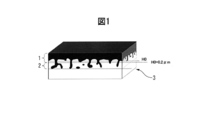
- the primary coating is divided into two regions in the plate thickness direction based on the geometrical features schematically shown in FIG. 1 to define the structure in each region.
- the term "surface oxide layer (1)” on the surface side and the term "inserted oxide layer (2)" on the base material steel sheet side are used to express two regions.
- the surface oxide layer (1) is a plate thickness at which a primary coating part that covers the surface of the base steel sheet relatively uniformly (hereinafter, this may be referred to as “surface oxide”) is present.
- the inlaid oxide layer (2) is a region in the plate thickness direction in which a primary coating portion (hereinafter, sometimes referred to as “inlaid oxide”) that has digged into the base steel sheet exists.
- the reference value H0 of the depth for dividing the two will be described later.
- the structure of the interface between the primary coating film and the base material steel sheet, in particular, the characteristic of the shape may be generally expressed by using the term "root".
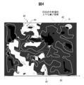
- the interface between the primary coating of the grain-oriented electrical steel sheet and the base steel sheet has an uneven shape in which the inlaid oxide penetrates into the base steel sheet.
- the penetration depth of the embedded oxide becomes deep and the number density (number/ ⁇ m 3 ) of the number of oxide particles increases, the adhesion of the primary coating to the base material steel plate increases due to the so-called anchor effect.
- the infiltrated oxide penetrates too much into the base steel sheet, it becomes a factor that hinders the crystal grain growth of the steel sheet during secondary recrystallization and the domain wall movement during magnetization, deteriorating the magnetic properties.
- the primary coating has the effect of imparting tension to the steel sheet and reducing iron loss.
- the surface oxide layer (1) preferably has a high content of Mg 2 SiO 4 having a small linear expansion coefficient, and the surface oxide layer (1) is preferably thick.
- the present inventors have found that the magnetic properties of the grain-oriented electrical steel sheet containing the magnetic property improving element and the annealing separator containing Y, La, Ce and Ca, Sr, and Ba.
- the adhesiveness of the primary coating formed by using was investigated and examined.
- one or more elements selected from the group consisting of Y, La, and Ce will be summarized and one or more elements selected from the group consisting of “Y group element”, Ca, Sr, and Ba will be summarized. May be described as "Ca group element”.
- the present inventors have obtained the following findings.
- the coating adhesion to the shearing process may be sufficient, but the coating adhesion to the bending process may not be sufficiently obtained. .. Further, a steel sheet that does not have good coating adhesion against bending often has poor iron loss and magnetic flux density.
- adheresion when it is not necessary to clearly distinguish between the film adhesion to shearing and the film adhesion to bending, it is simply described as "adhesion", and the film adhesion to shearing and the film adhesion to bending are included. Used as an intention. The present inventors further investigated the influence of the Y group element and the Ca group element in the annealing separator, and obtained the following findings.
- the embedded oxide layer (2) becomes thick. This improves the film adhesion to shearing.
- the annealing separator contains Ca group elements, if these elements are dispersed appropriately in the annealing separator, the number density of the inlaid oxide layer (2) of the formed primary coating increases. , The adhesion of the film to shearing is improved.
- the size of the particles containing the Ca group element in the Ca group element enriched region defined below in the primary coating is an appropriate size with respect to the MgO particle size, the coating adhesion to bending is high. Therefore, deterioration of magnetic characteristics can be suppressed.
- the surface oxide layer (1) has a uniform thickness and the Mg 2 SiO 4 phase increases.
- the improvement of the film adhesion to bending is that the thickness of the surface oxide layer (1) becomes uniform, and the local concentration of stress in the region where the surface oxide layer (1) is thin during bending is concentrated. It is thought that this is due to the avoidance of. Further, it is considered that the improvement of the magnetic properties is caused by the increase in the tension acting on the steel sheet because the amount of Mg 2 SiO 4 phase in the surface oxide layer (1) increases. Furthermore, it was clarified that the primary coating having such good characteristics is characterized not only by the shape of the interface irregularities but also by the morphology of Al existing near the interface of the primary coating.
- the characteristics of the annealing separator used to form such a primary coating were clarified.
- the interface between the base steel sheet and the primary coating has a complicated three-dimensional shape having irregularities as shown in FIG.
- the clarified characteristics of the existing form of Al should essentially be quantified as a "three-dimensional structure", but it was difficult to quantify because of its three-dimensional and complicated structure.
- the present inventors have attempted to define the characteristics of the interface on the “plane” by projecting information on the interface structure on a plane parallel to the steel sheet surface as described later. Then, it was confirmed that the effect of the present invention can be evaluated and explained by the quantitative definition by the "feature on the projection plane".
- the features of the present invention obtained from these findings are as follows. That is, if the primary coating mainly composed of Mg 2 SiO 4 and the interface between the primary coating and the base material steel plate satisfy the following characteristics (1) to (4), the embedded oxide layer (2) and the surface oxide The layer (1) becomes appropriate, and the adhesion of the primary coating against shearing and bending and the iron loss characteristics can both be achieved.
- the primary coating contains a Y group element and a Ca group element, and satisfies the following conditions (5) to (7). (5) Total content of Y group element: 0.1 to 6.0% by mass, (6) Total content of Ca group element: 0.1 to 6.0% by mass, (7) Number density D4 of Ca group element concentrated region: 0.008/ ⁇ m 2 or more.
- the above conditions (8) to (12) are realized at least in a region of 3.0 ⁇ m from the surface of the base steel plate in the layer of the annealing separating agent formed on the surface of the steel plate immediately before finish annealing.
- the raw material powder since particles of the raw material powder containing the Ca group element are likely to aggregate before being coated and dried on the surface of the steel sheet, in the raw material powder, (13) It is necessary to satisfy the number density of particles containing Ca group element ⁇ 25 billion particles/cm 3 .
- the gist of the present invention obtained from these findings is as follows.
- the grain-oriented electrical steel sheet according to the present invention is, in mass %, C: 0.0050% or less, Si: 2.5 to 4.5%, Mn: 0.02 to 0.2%, from the group consisting of S and Se.
- a primary coating containing 2 SiO 4 as a main component, and in the plate thickness direction of the steel plate, the base material steel sheet side is the positive side in the direction from the primary coating side to the base material steel sheet side.
- the surface height of the primary coating on the base steel sheet side The median value of H0 is H0, the primary coating existing on the base steel sheet side from H0+0.2 ⁇ m is “inserted oxide layer region”, and the primary coating existing on the primary coating side from H0+0.2 ⁇ m is “surface oxidation”.
- a region in which the maximum value of the characteristic X-ray intensity of Al is specified and the characteristic X-ray intensity of Al of 20% or more of the maximum value of the characteristic X-ray intensity of Al is obtained.
- Al concentrated region The primary coating is (1) Number density D3 of the Al concentrated region: 0.020 to 0.180 pieces/ ⁇ m 2 , (2) (Total area S5 of the area that is the inlaid oxide layer area and is the Al concentrated area)/(Total area S3 of the Al concentrated area) ⁇ 33% (3) A distance H5 obtained by subtracting H0 from the average value of the height in the plate thickness direction of the area that is the embedded oxide layer area and that is the Al concentrated area, H5: 0.4 to 4.0 ⁇ m, (4) (total area S1 of the inlaid oxide layer region)/(observation area S0) ⁇ 15% It is characterized by satisfying the condition of.
- the primary coating is one or more elements selected from the group consisting of Y, La, and Ce, and one or more elements selected from the group consisting of Ca, Sr, and Ba.
- the maximum value of the characteristic X-ray intensity of each of Ca, Sr, and Ba is specified, and 20% or more of the maximum value of the characteristic X-ray intensity of Ca is Area where characteristic X-ray intensity is obtained, area where characteristic X-ray intensity of Sr is 20% or more of maximum value of characteristic X-ray intensity of Sr, and 20% of maximum value of characteristic X-ray intensity of Ba.
- Ca group element enriched region When the above-mentioned region where the characteristic X-ray intensity of Ba is obtained is referred to as “Ca group element enriched region”, (5) The ratio of the total content of one or more elements selected from the group consisting of Y, La, and Ce to the content of Mg 2 SiO 4 in the primary coating: 0.1 to 6.0% by mass, (6) Ratio of the total content of one or more elements selected from the group consisting of Ca, Sr, and Ba to the content of Mg 2 SiO 4 in the primary coating: 0.1 to 6.0. mass%, (7) It is preferable that the condition that the number density D4 of the Ca-group element-enriched region is 0.008/ ⁇ m 2 or more is satisfied.
- the annealing separator used for manufacturing the grain-oriented electrical steel sheet according to the present invention is an annealing separator containing MgO as a main component, and one or more elements selected from the group consisting of Y, La, and Ce, and Ca, Sr, containing one or more elements selected from the group consisting of Ba, the ratio of the content of Mg, Y, La, Ce, Ca, Sr, Ba to the content of MgO (% by mass) Are respectively expressed as [Mg], [Y], [La], [Ce], [Ca], [Sr], and [Ba], (8) (0.253[Y]+0.180[La]+0.170[Ce])/0.454[Mg]: 0.40 to 3.60, (9) (0.353 [Ca] + 0.252 [Sr] + 0.195 [Ba])/0.454 [Mg]: 0.20 to 2.20,
- the average particle diameter R1 of MgO is 0.08 to 1.50 ⁇ m, (11) Average
- the annealing separator is preferably characterized in that the particles containing one or more elements selected from the group consisting of Y, La and Ce further contain oxygen.
- the production method of the grain-oriented electrical steel sheet according to the present invention comprises, in mass%, C: 0.1% or less, Si: 2.5 to 4.5%, Mn: 0.02 to 0.2%, S and Se.
- the substance that coats the surface of the steel sheet is the above-mentioned annealing separator.
- the method for producing a finish annealing steel sheet for producing a grain-oriented electrical steel sheet according to the present invention is, in mass %, C: 0.1% or less, Si: 2.5 to 4.5%, Mn: 0.02 to 0.2%, one or more elements selected from the group consisting of S and Se: 0.005 to 0.07% in total, sol.
- It comprises a step of producing and a step of applying an aqueous slurry to the surface of the decarburized annealed plate and drying, wherein the substance coating the steel plate surface after drying is the above-mentioned annealing separator. ..
- the grain-oriented electrical steel sheet according to the present invention has excellent magnetic properties and excellent adhesion of the primary coating to the base material steel sheet. Further, the annealing separator according to the present invention is used in the manufacturing process of the grain-oriented electrical steel sheet of the present invention.
- the grain-oriented electrical steel sheet of the present invention can be produced by the production method of the present invention using the annealing separator of the present invention.
- the surface of the side that was in close contact with the base material steel sheet of the primary coating separated from the grain-oriented electrical steel sheet is observed.
- This observation surface is analyzed by a scanning confocal laser scanning microscope to obtain the unevenness distribution of the interface (information in the depth direction of the interface). Further, the observation surface is analyzed using SEM-EDS, and the concentration distribution of various elements existing in the primary coating is obtained from the characteristic X-ray intensity.
- the obtained information is the information (position, characteristic X-ray intensity) of the primary coating having a three-dimensional structure on the steel sheet surface. It is projected on parallel planes. It is first noted that the following description of the interface in the present specification uses the "features on the projection plane". For example, the “area” related to the structure of the interface is the area obtained on the projection plane, and the region where the element exists is specified based on the characteristic X-ray intensity of the element obtained on the projection plane.
- the information of the primary film obtained on these projection planes can explain the features of the present invention without inconvenience, and the present invention is explained by the information of the primary film on these projection planes. Needless to say, this does not impair the significance of the present invention in which the three-dimensional structure of the primary coating is considered to be an essential feature.
- the notation “A to B” for the numerical values A and B means “not less than A and not more than B” unless otherwise specified. When a unit is attached only to the numerical value B in this notation, the unit is also applied to the numerical value A.
- the “main component” means a component contained in a certain substance in an amount of 50% by mass or more, preferably 70% by mass or more, and more preferably 90% by mass or more.
- the grain-oriented electrical steel sheet according to the present invention comprises a base material steel sheet and a primary coating formed on the surface of the base material steel sheet.
- the chemical composition of the base steel sheet forming the grain-oriented electrical steel sheet of the present invention contains the following elements. However, the feature of the present invention resides in the primary coating, and the base steel sheet does not need to be special.
- Carbon (C) is an element effective for controlling the structure until the completion of the decarburization annealing step in the manufacturing process, but if the C content exceeds 0.0050%, it is a product plate. The magnetic properties of the grain-oriented electrical steel sheet deteriorate. Therefore, the C content is 0.0050% or less. It is preferable that the C content is as low as possible. However, even if the C content is reduced to less than 0.0001%, only the manufacturing cost is required, and the above effect does not change so much. Therefore, the preferable lower limit of the C content is 0.0001%.
- Si 2.5-4.5%
- Si increases the electrical resistance of steel and reduces eddy current loss. If the Si content is less than 2.5%, the above effect cannot be sufficiently obtained. On the other hand, if the Si content exceeds 4.5%, the cold workability of the steel deteriorates. Therefore, the Si content is 2.5 to 4.5%.
- the lower limit of the Si content is preferably 2.6%, and more preferably 2.8%.
- the upper limit of the Si content is preferably 4.0%, and more preferably 3.8%.
- Mn 0.02 to 0.2%
- Manganese (Mn) combines with S and Se to form MnS and MnSe during the manufacturing process. These precipitates function as inhibitors (inhibitors of normal grain growth) and cause secondary recrystallization in steel. Mn further enhances the hot workability of steel. If the Mn content is less than 0.02%, the above effect cannot be sufficiently obtained. On the other hand, if the Mn content exceeds 0.2%, secondary recrystallization does not occur and the magnetic properties of the steel deteriorate. Therefore, the Mn content is 0.02 to 0.2%.
- the preferable lower limit of the Mn content is 0.03%, more preferably 0.04%.
- the preferable upper limit of the Mn content is 0.13%, more preferably 0.10%.
- One or more elements selected from the group consisting of S and Se 0.005% or less in total Sulfur (S) and selenium (Se) combine with Mn in the manufacturing process to function as an inhibitor MnS. And MnSe are formed.
- S sulfur
- Se selenium
- MnS metal-oxide-semiconductor
- the total content of these elements exceeds 0.005%, the magnetic properties deteriorate due to the remaining inhibitors. Further, segregation of S and Se may cause surface defects in the grain-oriented electrical steel sheet. Therefore, in the grain-oriented electrical steel sheet, the total content of one or more elements selected from the group consisting of S and Se is 0.005% or less.
- the total content of S and Se in the grain-oriented electrical steel sheet is preferably as low as possible.
- the preferable lower limit of the total content of one or more elements selected from the group consisting of S and Se in the grain-oriented electrical steel sheet is 0.0005%.
- sol. Al 0.010% or less
- Aluminum (Al) combines with N to form AlN and functions as an inhibitor during the production process of the grain-oriented electrical steel sheet.
- the Al content is 0.010% or less.
- the preferable upper limit of the Al content is 0.004%, and more preferably 0.003%. sol.
- the Al content is preferably as low as possible.
- the preferable lower limit of the Al content is 0.0001%. In the present specification, sol.
- Al means acid-soluble Al. Therefore, sol.
- the Al content is the content of acid-soluble Al.
- Al which is a feature of the primary coating of the present invention, is derived from the base steel sheet, as will be described later. Therefore, at first glance, the fact that the Al content of the base steel sheet is zero seems to contradict with the presence of Al in the primary coating, but the concentration in the primary coating is " In the grain-oriented electrical steel sheet of the present invention, which is "Al contained in the steel sheet", by the high temperature heat treatment also called “purification annealing” in one process of finish annealing after the concentration of Al, which is a feature of the present invention, occurs. Al of the base steel sheet is discharged out of the system. Therefore, there is no contradiction that the final base material steel plate does not contain Al and that the final primary coating film contains Al derived from the base material steel plate.
- N 0.010% or less Nitrogen (N) forms AlN by combining with Al during the manufacturing process of the grain-oriented electrical steel sheet, and functions as an inhibitor.
- N content in the grain-oriented electrical steel sheet exceeds 0.01%, the above-mentioned inhibitor excessively remains in the grain-oriented electrical steel sheet, and the magnetic properties deteriorate. Therefore, the N content is 0.01% or less.
- the preferable upper limit of the N content is 0.004%, and more preferably 0.003%.
- the N content is preferably as low as possible. However, even if the total content of N in the grain-oriented electrical steel sheet is reduced to less than 0.0001%, the manufacturing cost only increases and the above effect does not change so much. Therefore, the preferable lower limit of the N content in the grain-oriented electrical steel sheet is 0.0001%.
- the balance of the chemical composition of the base steel sheet of the grain-oriented electrical steel sheet according to the present invention consists of Fe and impurities.
- the impurities when industrially producing the base steel sheet, ore as a raw material, scrap, or those mixed from the production environment, or in the steel without being completely purified in the purification annealing.
- the following remaining elements and the like are meant as long as they are permitted within a range that does not adversely affect the grain-oriented electrical steel sheet of the present invention.
- the total content of one or more elements selected from the group consisting of Cu, Sn, Sb, Bi, Te and Pb is preferably 0.30% or less. Since these elements are impurities as described above, the total content of these elements is preferably as low as possible.
- a grain-oriented electrical steel sheet having a primary coating formed on its surface is subjected to constant potential electrolysis in an electrolytic solution so that only the base steel sheet is dissolved, and then the primary coating is separated from the base steel sheet to obtain an observation sample.
- electrolysis for sampling since the base material steel sheet at the interface is selectively electrolyzed, it is not necessary to electrolyze all the base material steel sheet, and an appropriate amount of electrolysis may be set. The amount of electrolysis is, for example, 80 C/cm 2 .
- the primary coating is applied to the adhesive surface of a commercially available metal tape, etc., the base metal steel plate is then removed, and the remaining tape is observed, or embedded with paraffin.
- the separated primary coating may be referred to as an “interface observation sample”, and the surface of the primary coating to be observed that is in close contact with the base steel sheet may be referred to as an “observation surface”.
- the interface observation sample is observed with various types of observation equipment from the direction perpendicular to the surface of the steel sheet from which it was peeled (the thickness direction of the grain-oriented electrical steel sheet). Therefore, the data obtained from each device is the information of the interface observation sample developed on the projection plane.
- the following description will be made on the premise of data on this projection plane. That is, for example, the description “at the interface” is a description of the situation of data on the projection plane.
- the direction from the primary coating film side to the base material steel plate side is positive.
- the term “height” used below means that the direction from the primary coating side to the base steel sheet side is high.
- the observed surface of the interface observation sample is subjected to characteristic X-ray intensity analysis of Ca, Sr, Ba and Al using SEM-EDS (model number: JSM-7900F, manufactured by JEOL Ltd.).
- the scanning step is set to 0.1 ⁇ m, a characteristic X-ray intensity distribution chart of 200 ⁇ 150 pixels on the projection plane is obtained, and each observation region of arbitrary 200 ⁇ 150 pixels is selected.
- a region that completely includes the observation region and is not in contact with each observation region on which the characteristic X-ray intensity analysis is performed is a scanning confocal laser microscope (model number: VK9710, manufactured by Keyence Corporation). ), and obtain the unevenness data of the observation plane on the projection plane.
- the scanning step is 0.1 ⁇ m.
- the obtained data array of 200 ⁇ 150 pixels is smoothed once by a Gaussian filter (FIG. 2) of size 3 ⁇ 3. Further, automatic quadric surface correction is performed on the smoothed data array with the center line in the width direction and the center line in the height direction as a reference to obtain the corrected data array.
- the scanning step of the unevenness measurement is set to D ⁇ m, which is not 0.1 ⁇ m
- the unevenness data array is reduced to a size of 0.1/D times by bilinear complementation, and the data point interval is artificially set to 0. An uneven distribution of 1 ⁇ m is obtained.
- FIG. 3 is a schematic view showing a three-dimensional structure of the back surface of the peeled primary coating and the fitting portion.
- H0 is the median value of the surface height of the primary coating.
- H1 is an average value of the heights of the fitting portions existing at positions higher than H0. This position (H1-H0) is 0.40 to 2.00 ⁇ m in the present invention.
- FIG. 3 is projected onto a plane parallel to the surface of the steel plate, and the projection plane has height unevenness distribution information. Then, from the uneven distribution, a data array of 200 ⁇ 150 points at a position corresponding to each area of 200 ⁇ 150 pixels selected from the characteristic X-ray intensity distribution map is specified. That is, for each area of 200 ⁇ 150 pixels of the digital image of the characteristic X-ray intensity distribution map, all pixels have one unevenness data (height).
- this is referred to as a characteristic X-ray intensity and height correlation distribution chart, and a schematic diagram showing this is shown in FIG. The method of identifying the morphology of the coating with the information obtained from this figure will be described.
- areas A0 to A5 described below are determined in the observation area by the following procedure.
- A0 In the schematic view of the characteristic X-ray intensity and unevenness correlation distribution chart shown in FIG. 4, all the observation areas in the outermost frame are indicated by A0.
- the region filled with dark gray is a region higher than the median value H0 of the unevenness.
- the inside of the frame indicated by the light gray line is a region (inserted oxide region) A1 which is 0.2 ⁇ m higher than H0. Outside the frame indicated by the light gray line is the surface oxide layer region A2.
- the Al (aluminum) concentrated region is represented by A3 (shown by dots) and A5 (shown by black).
- A5 indicates an Al (aluminum) concentrated region existing in the inlaid oxide region (A1).
- the area A4 (inside the frame of the dotted line) shows the Ca group element concentrated area described below.
- the area A0 is the entire observation area, that is, an area of 20 ⁇ m ⁇ 15 ⁇ m, and all pixels in the characteristic X-ray intensity and height correlation distribution map correspond to this area A0.
- A0 may be described as an “observation region”.
- the area A1 and the area A2 are classified based on the characteristic X-ray intensity and the height distribution of the height correlation distribution chart.
- the primary coating is not classified into two regions in the plate thickness direction based on the position H0 in the plate thickness direction, that is, the "inserted oxide layer (2)" and the "surface oxide layer (1)". , As described above (FIG. 1).
- Areas A1 and A2 are areas where this classification is developed on the projection plane.
- H0 is the median value of the surface height of the primary coating of the height data of the characteristic X-ray intensity and height correlation distribution chart. Here, it is an arithmetic average value of two height values of 200 ⁇ 150 close to the center.
- the region having a height of H0+0.2 ⁇ m or more in the plate thickness direction is the “inserted oxide layer (2)”, and what is seen on the projection plane is the “inserted oxide layer region” A1.
- the area having a height of less than H0+0.2 ⁇ m in the plate thickness direction is the “surface oxide layer (1)”, and is the “surface oxide layer area” A2 on the projection plane.
- the area A3 and the area A4 are classified based on the characteristic X-ray intensity and the height distribution of the height correlation distribution chart.
- the maximum value of the characteristic X-ray intensity of Al is specified, and 20% of the maximum value of the characteristic X-ray intensity of the Al is specified.
- the region where the above characteristic X-ray intensity of Al can be obtained is A3.
- the region A3 will be referred to as "Al concentrated region”.
- the characteristic X-ray intensities of Ca, Sr, and Ba are specified, and the characteristic X-ray intensity of Ca that is 20% or more of the maximum value of the characteristic X-ray intensity of Ca is Obtained region, region where Sr characteristic X-ray intensity of 20% or more of maximum value of Sr characteristic X-ray intensity is obtained, and Ba characteristic X-ray of 20% or more of maximum value of Ba characteristic X-ray intensity A4 is a region including the region where the intensity is obtained. That is, the region A4 is a region in which the characteristic X-ray intensity of any element of Ca, Sr, and Ba is 20% or more of the maximum characteristic X-ray intensity of the element.
- the area A4 will be referred to as "Ca group element concentrated area”.
- A5 a region existing in the inlaid oxide layer region A1 and being an Al (aluminum) concentrated region A3 is specified as A5.
- the area A5 will be referred to as an “inserted Al (aluminum) area”.
- the number density (number/ ⁇ m 2 ) of the number of each region, the total area ( ⁇ m 2 ) of each region, and the position (height ( ⁇ m)) in the plate thickness direction of each region are specified. Areas are required for the areas A0, A1, A3, and A5, and their total areas are S0, S1, S3, and S5. It is A3 and A4 that the number density of the number of regions is required. The number densities of the numbers of the areas A3 and A4 are D3 and D4, respectively. In specifying the number density of the number of regions, when the pixels in 200 ⁇ 150 pixels are continuous vertically or horizontally, these are regarded as one region.
- a region consisting of three or less pixels is regarded as noise and excluded, and the number of regions is specified.
- the area of one pixel is 0.1 ⁇ m ⁇ 0.1 ⁇ m (more specifically, since the scanning step at the time of measurement is 0.1 ⁇ m (more specifically, 0.092 ⁇ m), the area of one pixel is 0.092 ⁇ m ⁇ 0.092 ⁇ m) ⁇ number of regions.
- D3 is the area of the observation area A0 (that is, the total observation area S0, which is the total number of areas measured by regarding the area A3 in which the pixels are continuous in pixels as one area). ) Divided by. D4 is calculated by the same method.
- the region A5 is required to have a position in the plate thickness direction.
- the position of the area A5 is H5. Note that this position is specified with reference to H0, which is the boundary between the surface oxide layer (1) and the fitting oxide layer (2). Specifically, it is a value obtained by subtracting H0 from the average value of the heights of all the pixels in the area A5. Since the region A5 is a region where the height in the characteristic X-ray intensity and height correlation distribution chart exists at a position of H0+0.2 ⁇ m or more, the average height of the pixels in the region A5 is always H0+0.2 ⁇ m or more, As a result, H5 becomes a value of 0.2 ⁇ m or more.
- the characteristic primary coating film of the present invention will be described below.
- the primary coating of the present invention contains Mg 2 SiO 4 as a main component, but the Al distribution in the vicinity of the interface between the primary coating and the base steel sheet has a major characteristic. First, this will be described.
- the present invention is characterized in that D3, which is the number density of the Al concentrated region A3 near the interface, is D3: 0.020 to 0.180/ ⁇ m 2 . If D3 is out of this range, the effect of improving the coating adhesion to bending cannot be obtained.
- the ratio of the area of the inserted Al region A5 existing in the inserted oxide layer region A1 to the Al concentrated region A3, that is, S5/S3 is S5/S3 ⁇ 0.33 (33%). To do. If this ratio is less than 0.33, the effect of improving the coating adhesion to bending cannot be obtained. Further, the position H5 of the fitted Al region A5 in the plate thickness direction is characterized by H5: 0.4 to 4.0 ⁇ m. If this value is less than 0.4 ⁇ m, the effect of improving the coating adhesion to bending cannot be obtained.
- the state where the value of H5 exceeds 4.0 ⁇ m means that the inlaid oxide layer (2) itself is excessively thick, and the oxide hinders the domain wall movement at the time of magnetization, so that the magnetic characteristics are not affected. Negative effects will be seen.
- Al is an element having a strong tendency to form an oxide
- Al is selectively oxidized on the surface of the steel sheet, and Al diffuses from the inside of the base steel sheet toward the surface.
- the final film tension is lowered to deteriorate the magnetic properties, and the main component is Mg 2 SiO 4.
- the thickness of the surface oxide layer (1) becomes uneven.
- the solution may be to oxidize Al inside the steel sheet to prevent it from reaching the surface oxide layer (1).
- Al may be oxidized and fixed in the tip region of the inlaid oxide deeply penetrating the base steel plate.
- the present invention has a structure in which Al is concentrated in the tip region of the embedded oxide layer (2).
- the state of Al in the Al concentrated region A3 is not specified at all, but considering that the main component of the primary coating is Mg 2 SiO 4 , Al in A3 exists as an oxide. Therefore, it is considered that the above situation is realized and the improvement of the magnetic properties and the improvement of the film adhesion to the bending process are achieved at the same time.
- the specified value representing this situation is H5, and if H5 is 0.4 ⁇ m or more, that is, if the inserted Al region A5 is inside the steel sheet at a distance of 0.4 ⁇ m or more from H0 (the tip side of the inserted oxide), the above state is It is considered to have been achieved.
- the fact that such an inlaid Al region is at the tip of the inlaid oxide layer (2) also leads to D3 being a numerical value within an appropriate range. That is, if the number density of the inserted Al region A5 is small and Al reaches the entire interface, D3 will be low.
- an appropriate range of D3 is 0.020 to 0.180 pieces/ ⁇ m 2 . Further, if the appropriate fitting Al region A5 as described above is formed, Al diffused from the inside of the steel sheet will not reach the surface oxide layer, so that S5/S3 will inevitably have a high value. It is considered that the specified 0.33 is the lower limit.
- the primary coating of the present invention contains Mg 2 SiO 4 as a main component. More specifically, the primary coating contains 50-95 wt% Mg 2 SiO 4 .
- the balance is mainly commonly known oxides such as MgAl 2 O 4 and sulfides of Mn and alkaline earth metals.
- the primary coating of the present invention contains 0.1 to 6.0 mass% of Y group elements in total and 0.1 to 6.0 mass% of Ca group elements in total with respect to the content of Mg 2 SiO 4 in the primary coating. It is preferable to contain 1 to 6.0% by mass. Although details will be described later, in order to realize the above Al distribution, it is preferable to use an annealing separator containing a Y group element. In this case, the Y group element remains in the primary coating after the finish annealing. When the total content of Y group elements in the primary coating is less than 0.1% by mass, the coating adhesion to bending is not improved. If it exceeds 6.0 mass %, the thickness of the inlaid oxide layer (2) becomes too thick, so that the adverse effect on the magnetic properties becomes remarkable.
- an annealing separator containing a Ca group element in order to realize the above Al distribution, it is preferable to use an annealing separator containing a Ca group element.
- the Ca group element will remain in the primary coating after the finish annealing. If the total content of Ca group elements in the primary coating is less than 0.1% by mass, the coating adhesion in bending cannot be improved. If it exceeds 6.0% by mass, the number density of the oxide particles in the embedded oxide layer (2) becomes too high, and the adjacent embedded oxides coalesce into one body, resulting in the number of embedded oxide particles. Not only the density is lowered, but also a characteristic Al distribution is not obtained, and the coating adhesion in bending cannot be improved.
- the content of Mg 2 SiO 4 in the primary coating is quantitatively analyzed by inductively coupled plasma mass spectrometry (ICP-MS) using the primary coating separated from the magnetic steel sheet by the method described above as a sample.
- the product of the obtained quantitative value (mass %) and the molecular weight of Mg 2 SiO 4 is divided by twice the atomic weight of Mg to obtain the content of Mg 2 SiO 4 .
- quantitative analysis is performed by the same method as above, and the same calculation as above is performed for the obtained content value (mass %). Then, the contents of these elements were calculated.
- the total content of the obtained Ca, Ba and Sr was defined as "Ca group element content”
- the total content of the obtained La, Y and Ce was defined as "Y group element content”.
- the “number density of Ca group element concentrated regions” D4 on the projection plane is 0.008 pieces/ ⁇ m 2 or more.
- the number density D4 of the Ca group element-enriched region in the primary coating defined here represents the form in which the Ca group element that has acted on the formation of the inlaid oxide during the formation of the primary coating remains in the primary coating. it is conceivable that.
- D4 becomes higher, Ca group elements are uniformly supplied to the inlaid oxide, so that the number density D3 of the Al-based oxide becomes higher, and at the same time, the ingress of oxide into the base steel material is promoted.
- D4 is less than 0.008 particles/ ⁇ m 2 , not only the number density of the embedded oxide particles is not sufficiently obtained and the adhesion is not improved, but also the above-mentioned characteristic Al distribution cannot be obtained. If D4 is too high, the frequency of formation of the intruding oxide particles formed in association therewith becomes excessively high, and as in the case of excessively high D3, adjacent injecting oxides coalesce and integrate. Therefore, formation of a characteristic Al distribution is hindered. Therefore, D4 is 2.000 pieces/ ⁇ m 2 or less.
- An example of the method for manufacturing the grain-oriented electrical steel sheet according to the present invention will be described.
- An example of a method for producing a grain-oriented electrical steel sheet includes a steel making step, a hot rolling step, a hot rolled sheet annealing step, a cold rolling step, a decarburizing annealing step, an annealing separator layer forming step, and a finishing annealing step. Equipped with.
- each step will be described.
- the processing conditions of the following steps do not deviate from the general range and do not need to be special.
- Characteristic in the method of the present invention is an annealing separator for controlling the structure of the primary coating, which coats the surface of the steel sheet before finish annealing.
- molten steel is melted by a usual method such as a converter, and a well-known refining process and casting process are carried out to manufacture a slab having the following chemical composition.
- a well-known refining process and casting process are carried out to manufacture a slab having the following chemical composition.
- some of the elements contained in the slab are discharged from the steel in the decarburization annealing and finish annealing steps described below.
- C for controlling primary recrystallization and S, Al, N, etc. functioning as inhibitors are largely removed. Therefore, the chemical composition of the slab is different from that of the steel sheet of the final product.
- the C content in the slab is 0.100 mass% or less.
- the preferable upper limit of the C content in the slab is 0.092% by mass, more preferably 0.085% by mass. Further, if the C content is less than 0.005 mass%, the dispersed state of precipitates such as MnS, MnSe, and AlN and the steel grain structure after decarburization annealing cannot be uniformly obtained, and Goss after secondary recrystallization is not obtained. The azimuth integration degree may be deteriorated. Therefore, the lower limit of the C content in the slab is 0.005% by mass.
- the preferable lower limit of the C content in the slab is 0.020% by mass, and more preferably 0.040% by mass.
- Si 2.5 to 4.5 mass%
- Si enhances the electric resistance of steel, but if it is present in excess, the cold workability deteriorates.
- the Si content in the slab is 2.5 to 4.5 mass %
- the Si content in the grain-oriented electrical steel sheet after the finish annealing step will be 2.5 to 4.5 mass %.
- the upper limit of the Si content in the slab is preferably 4.0%, more preferably 3.8% by mass.
- the lower limit of the Si content in the slab is preferably 2.6% by mass, and more preferably 2.8% by mass.
- Mn 0.02 to 0.20 mass%
- Mn combines with S and Se to form a precipitate during the manufacturing process, and functions as an inhibitor. Mn further enhances the hot workability of steel.
- the Mn content in the slab is 0.02 to 0.20 mass %
- the Mn content of the grain-oriented electrical steel sheet after the finish annealing step is 0.02 to 0.20 mass %.
- the preferable upper limit of the Mn content in the slab is 0.13% by mass, more preferably 0.10% by mass.
- the preferable lower limit of the Mn content in the slab is 0.03 mass%, more preferably 0.04 mass%.
- One or more elements selected from the group consisting of S and Se 0.005 to 0.070 mass% in total
- sulfur (S) and selenium (Se) combine with Mn to form MnS and MnSe. Both MnS and MnSe function as inhibitors necessary for suppressing grain growth during secondary recrystallization. If the total content of one or more elements selected from the group consisting of S and Se is less than 0.005% by mass, the above effect is difficult to be obtained. On the other hand, if the total content of one or more elements selected from the group consisting of S and Se exceeds 0.070 mass %, secondary recrystallization does not occur during the manufacturing process and the magnetic properties of the steel deteriorate. To do.
- the total content of one or more elements selected from the group consisting of S and Se is 0.005 to 0.070 mass %.
- the preferable lower limit of the total content of one or more elements selected from the group consisting of S and Se is 0.008% by mass, and more preferably 0.016% by mass.
- the preferable upper limit of the total content of one or more elements selected from the group consisting of S and Se is 0.060% by mass, and more preferably 0.050% by mass.
- sol. Al 0.005 to 0.050 mass%
- AlN functions as an inhibitor.
- the Al content is 0.005 to 0.050 mass %.
- the preferable upper limit of the Al content is 0.040% by mass, and more preferably 0.035% by mass.
- the preferable lower limit of the Al content is 0.010% by mass, and more preferably 0.015% by mass.
- N 0.001 to 0.030 mass%
- nitrogen (N) combines with Al to form AlN that functions as an inhibitor. If the N content in the slab is less than 0.001% by mass, the above effect cannot be obtained. On the other hand, if the N content in the slab exceeds 0.030% by mass, AlN becomes coarse. In this case, AlN becomes difficult to function as an inhibitor, and secondary recrystallization may not occur. Therefore, the N content in the slab is 0.001 to 0.030 mass %.
- the preferable upper limit of the N content in the slab is 0.012% by mass, more preferably 0.010% by mass.
- the preferable lower limit of the N content in the slab is 0.005% by mass, and more preferably 0.006% by mass.
- the balance of the chemical composition in the slab of the present invention consists of Fe and impurities.
- the impurities are those that are mixed in from the ore as a raw material, scrap, or the manufacturing environment when the slab is industrially manufactured, and are allowed within a range that does not adversely affect the slab of the present embodiment. Means something.
- the slab according to the present invention may further contain, in place of a part of Fe, one or more elements selected from the group consisting of Cu, Sn and Sb in a total of 0.60 mass% or less. Further, the slab according to the present invention may further contain, in place of a part of Fe, one or more elements selected from the group consisting of Ca, Ba and Sr in a total amount of 0.02 mass% or less. All of these elements are arbitrary elements.
- One or more elements selected from the group consisting of Cu, Sn and Sb: 0 to 0.6 mass% in total Cu (copper), tin (Sn) and antimony (Sb) are all optional elements and may not be contained.
- Cu, Sn and Sb all increase the magnetic flux density of the grain-oriented electrical steel sheet. If Cu, Sn, and Sb are contained in any amount, the above effect can be obtained to some extent. However, if the total content of Cu, Sn and Sb exceeds 0.60% by mass, it becomes difficult to form the internal oxide layer during decarburization annealing.
- the total content of one or more elements selected from the group consisting of Cu, Sn and Sb is 0 to 0.60 mass %.
- a preferable lower limit of the total content of one or more elements selected from the group consisting of Cu, Sn, and Sb is 0.005% by mass, and more preferably 0.007% by mass.
- the preferable upper limit of the total content of one or more elements selected from the group consisting of Cu, Sn and Sb is 0.50% by mass, and more preferably 0.45% by mass.
- the slab according to the present invention may further contain, in place of a part of Fe, one or more elements selected from the group consisting of Bi, Te and Pb in a total amount of 0.030 mass% or less. All of these elements are arbitrary elements.
- One or more elements selected from the group consisting of Bi, Te and Pb: 0 to 0.030 mass% in total Bismuth (Bi), tellurium (Te), and lead (Pb) are all optional elements, but they are noteworthy elements in the present invention from the following viewpoints. These elements increase the magnetic flux density of the grain-oriented electrical steel sheet.
- the preferable lower limit value of the total content of one or more elements selected from the group consisting of Bi, Te and Pb is 0.0005% by mass, and more preferably 0.0010% by mass.
- the inlaid oxide layer (2) does not become thick and the coating adhesion of the primary coating deteriorates.
- the amount of addition has to be limited to about 0.030 mass% or less in order to secure the coating adhesion despite having the effect of increasing the magnetic flux density. Since the effect of the present invention improves the film adhesion by changing the structure of the oxide to be inserted, it is also particularly effective when a manufacturing method containing these elements is applied. When the present invention is applied, even if these elements are 0.010% by mass or more, and further 0.015% by mass or more, it becomes possible to secure good film adhesion.
- the upper limit is made 0.0300 mass %.
- a preferable upper limit is 0.0200% by mass, and a more preferable upper limit is 0.0150% by mass.
- Hot rolling process A slab having the above chemical composition is heated.
- the heating temperature of the slab is, for example, more than 1280°C to 1350°C.
- Hot rolling is performed on the heated slab to produce a hot rolled steel sheet.
- the hot-rolled steel sheet may be annealed if necessary.
- Cold rolling process In the cold rolling step, cold rolling is performed on the hot rolled steel sheet to produce a cold rolled steel sheet.
- Cold rolling is performed on the prepared hot-rolled steel sheet to produce a cold-rolled steel sheet which is the base steel sheet.
- Cold rolling may be carried out only once, or may be carried out plural times.
- intermediate annealing for the purpose of softening is performed, and then cold rolling is further performed.
- Cold rolling is performed once or a plurality of times to manufacture a cold rolled steel sheet having a product sheet thickness (sheet thickness as a product).
- the cold rolling rate in one or more times of cold rolling is 80% or more.
- the cold rolling rate (%) is defined as follows.
- Cold rolling ratio (%) (1-plate thickness of cold rolled steel plate after last cold rolling/plate thickness of hot rolled steel plate before start of first cold rolling) ⁇ 100
- the preferable upper limit of the cold rolling rate is 95%. Further, before performing cold rolling on the hot rolled steel sheet, heat treatment may be performed on the hot rolled steel sheet, or pickling may be performed.
- Decarburization annealing is performed on the cold rolled steel sheet manufactured by the cold rolling step, and nitriding annealing is performed as necessary.
- the decarburization annealing is performed in a well-known wet atmosphere containing hydrogen and nitrogen.
- the decarburization annealing reduces the C concentration of the grain-oriented electrical steel sheet to 50 ppm or less, which can suppress the magnetic aging deterioration.
- the decarburizing annealing step primary recrystallization occurs at the same time and the working strain introduced by cold rolling is released.
- an internal oxide layer containing SiO 2 as a main component is formed on the surface layer portion of the base steel sheet.
- the SiO 2 formed here reacts with MgO in the aqueous slurry containing the annealing separator applied subsequently during the finish annealing to form a primary coating whose morphology is controlled in the present invention.
- the conditions for the decarburization annealing step are well known, and the maximum temperature is, for example, 750 to 950°C.
- the holding time at the temperature is, for example, 1 to 5 minutes.
- the "annealing separating agent" refers to a substance that coats the surface of the above decarburized and annealed sheet that is subjected to finish annealing, mainly for the purpose of preventing seizure of the steel sheet during finish annealing.
- an aqueous slurry containing a compound that constitutes the annealing separator is prepared.
- the aqueous slurry is prepared by mixing and stirring a compound containing an element constituting the annealing separator with water. This slurry is applied to the surface of the above decarburized and annealed plate with a roll coater, a spray, or the like.
- the steel sheet coated with the slurry is inserted into a furnace kept at 400 to 1000° C. and kept for 10 to 90 seconds to dry the slurry on the surface. At this time, the temperature of the steel sheet itself rises only up to about 400°C. For this reason, no remarkable change in crystal structure such as grain growth occurs in the steel sheet, and water is evaporated and discharged in the slurry, and part of the contained elements reacts with water to form a compound containing oxygen.
- the decarburized annealed sheet coated with the annealing separator is referred to as a finish annealing steel sheet. Basically, it can be considered that the annealing separator finally covering the surface of the steel sheet before finish annealing is simply a mixture of various compounds used as the raw materials.
- finish annealing After the annealing separator is dried, finish annealing is performed.
- the finish annealing the annealing temperature is set to 1150 to 1250° C., and the decarburized annealed sheet coated with the annealing separator is annealed.
- the soaking time is, for example, 15 to 30 hours.
- the atmosphere in the furnace during finish annealing is a known atmosphere.
- a part of the elements such as S, Al, and N that function as inhibitors are discharged out of the system. This process is sometimes called "purification (annealing)".
- the grain-oriented electrical steel sheet manufactured by the above manufacturing process a primary coating film containing Mg 2 SiO 4 as a main component is formed on the surface.
- the grain-oriented electrical steel sheet of the present invention is obtained in which the interface structure between the base steel sheet and the primary coating satisfies the requirements of the invention, and the coating adhesion is improved.
- the grain-oriented electrical steel sheet according to the present invention may further be subjected to an insulating coating forming step after the finish annealing step.
- an insulating coating forming step a well-known insulating coating agent mainly containing colloidal silica and phosphate is applied to the surface of the grain-oriented electrical steel sheet after finish annealing, and then baking is performed. These treatments do not impair the effects of the present invention, and an insulating coating having a function of imparting tension to the steel sheet is formed on the primary coating.
- the grain-oriented electrical steel sheet according to the present invention may be further subjected to a well-known magnetic domain subdivision treatment step after cold rolling, decarburization annealing, finish annealing, or formation of an insulating film.
- a well-known magnetic domain subdivision treatment step distortion is imparted to the surface of the grain-oriented electrical steel sheet by laser irradiation, rolling with a convex roll, or a groove is formed on the surface by laser irradiation or etching. These treatments do not hinder the effect of the present invention and can be expected to improve the magnetic properties.
- the annealing separator of the present invention contains magnesium oxide (MgO) as a main component, and further comprises one or more elements (Y group elements) selected from the group consisting of Y, La, and Ce, and Ca, Sr, and Ba. It contains at least one element (Ca group element) selected from the group consisting of
- ⁇ Y, La, Ce> The proportion of each content of Y, La, Ce, and Mg with respect to the content of MgO in the annealing separator is represented by mass%, and is [Y], [La], [Ce], and [Mg].
- Y, La, and Ce atoms present in the annealing separator are contained as Y 2 O 3 , La 2 O 3 , CeO 2, and MgO which are stable oxides. It can be calculated as follows with the coefficient calculated.
- CY is the volume ratio between the total content of the Y group elements in the annealing separator as stable oxides of each element and the total content, and MgO, which is the main constituent in the annealing separator. In other words, it can also be said to be an index showing the magnitude of the influence of the Y group element on Mg in the oxide.
- the particles containing the Y group element can contain the Y group element as a simple substance, an alloy, or a compound, but as a compound containing oxygen or a substance that is oxidized during finish annealing to be converted to a compound containing oxygen. It is preferable to contain it.
- the compound containing oxygen is, for example, an oxide, a hydroxide, a carbonate, a sulfate or the like. This may be, of course, mixed as a raw material, or may be changed to a compound containing oxygen in the drying process of the above-mentioned annealing separator layer forming step, for example.
- CY is 0.40 to 3.60.
- the preferable lower limit of CY is 0.80, and more preferably 1.20.
- the preferable upper limit is 3.20, and more preferably 2.80.
- the thickness of the inlaid oxide layer (2) can be controlled by controlling the content of the Y group element is not clear, but it is considered as follows.
- the Y group element reacts with oxygen in the annealing separating agent not only when it is a compound containing oxygen as an annealing separating agent, but also contains oxygen. Exists as a compound.
- the compound decomposes to release oxygen.
- Mg 2 SiO 4 is an oxide that is stable even at a high temperature of finish annealing and in a hydrogen atmosphere, and as a result, a thick embedded oxide layer (2) is formed.
- the annealing separator has the following formula: (0.353 [Ca]+0.252 [Sr]+0.195 [Ba])/0.454 [Mg] ⁇ 0.20 to 2.20 Contains only the amount that satisfies the above. Below, (0.353 [Ca]+0.252 [Sr]+0.195 [Ba])/0.454 [Mg] may be described as CC.
- each coefficient of the above equation is calculated by considering that Ca, Ba, Sr, and Mg atoms present in the annealing separator are contained as the respective stable oxides CaO, BaO, SrO, and MgO.
- the coefficient can be calculated as follows.
- CC is a volume ratio between the total content of the Ca group elements in the annealing separator as a stable oxide of each element and the total content, and MgO which is a main constituent in the annealing separator. In other words, it can also be said to be an index showing the magnitude of the influence of the Ca group element on Mg in the oxide.
- the particles containing the Ca group element can contain the Ca group element as a simple substance, an alloy, or a compound, but as a compound containing oxygen or a substance that is oxidized during finish annealing to be converted to a compound containing oxygen. It is preferable to contain it.
- the compound containing oxygen is, for example, an oxide, a hydroxide, a carbonate, a sulfate or the like. This may be, of course, mixed as a raw material, or may be changed to a compound containing oxygen in the drying process of the above-mentioned annealing separator layer forming step, for example.
- the Ca group element reacts with SiO 2 existing in the surface area of the mother steel sheet as a starting point of the formation of the primary coating to facilitate the formation of an inlaid oxide, that is, to increase the number density of the inlaid oxide layer area.
- SiO 2 existing in the surface area of the mother steel sheet as a starting point of the formation of the primary coating to facilitate the formation of an inlaid oxide, that is, to increase the number density of the inlaid oxide layer area.
- the Ca group element has a function similar to that of Mg, but comparing the diffusion rates of Mg and Ca group element in SiO 2 shows that the Ca group element is faster, so that the Ca group element is present in the annealing separator.
- the complex oxide of SiO 2 and Ca group element is formed in the inner region of the mother steel plate earlier than Mg 2 SiO 4 which is the complex oxide of SiO 2 and Mg, and the inserted oxide progresses to the inside of the steel plate earlier. Make it stable over time.
- the injecting oxide is mainly a composite oxide of Ca and Si, but thereafter, Mg that arrives later forms a more stable oxide than Ca, so the oxide composition gradually changes and Specifically, it is replaced with Mg 2 SiO 4 which is a main constituent material of the primary coating.
- the annealing separator containing the Ca group element increases the number density of the embedded oxide layer region of the primary coating. It is considered that the Ca group element discharged from the oxide by the replacement with Mg is bonded to S in the base steel sheet to form a sulfide. In this process, finally Ca remaining in the primary coating is observed as the Ca group element contained in the primary coating and the number density D4 of the Ca group element concentrated region.
- CC is less than 0.20, the above effect cannot be sufficiently obtained.
- the CC exceeds 2.20, the number density becomes excessively high in the initial process of forming the inlaid oxide, which hinders the movement of the domain wall and deteriorates the iron loss.
- CC 0.20 to 2.20, the adhesion of the primary coating to the base steel sheet can be enhanced while suppressing the deterioration of iron loss.
- the annealing separator may further contain Ti, Zr, and Hf, if necessary.
- Ti group element one or more elements selected from the group consisting of Ti, Zr, and Hf may be described as “Ti group element”.
- the proportions of the respective contents of Ti, Zr, Hf, and Mg with respect to the content of MgO in the annealing separator are represented by mass% and are [Ti], [Zr], [Hf], and [Mg].
- the annealing separator has the following formula: (0.370[Ti]+0.238[Zr]+0.122[Hf])/0.454[Mg] ⁇ 6.50 Contains only the amount that satisfies the above.
- each coefficient of the above formula contains Ti, Zr, Hf, and Mg atoms present in the annealing separator as the respective stable oxides TiO 2 , ZrO 2 , HfO 2, and MgO.
- the coefficient is calculated as follows and can be calculated as follows.
- CT is the volume ratio of the Ca group elements in the annealing separator as the stable oxides of the respective elements, the total content, and MgO, which is the main constituent in the annealing separator. In other words, it can also be said to be an index showing the magnitude of the influence of the Ca group element on Mg in the oxide.
- the particles containing the Ti group element can contain the Ti group element as a simple substance, an alloy, or a compound.
- the compound is, for example, sulfate, carbonate, hydroxide or the like.
- the Ti group element accelerates the reaction between MgO in the annealing separator and SiO 2 on the surface layer of the mother steel sheet formed by decarburization annealing during finish annealing, and promotes the formation of Mg 2 SiO 4 .
- CT exceeds 6.50, the effect is saturated, and the iron loss may be deteriorated due to excessive film development.
- the annealing separator may contain an element whose known effect is known within a range not impairing the effect of the present invention.
- the annealing separating agent of the present invention contains the above-mentioned various elements, but they are present not only as elemental metals but also in the state of being mixed as various compounds.
- the present invention makes several provisions regarding this mixed situation.
- the average particle size of MgO is 0.08 to 1.50 ⁇ m.
- the average particle size of MgO is described as R1.
- R1 is less than 0.08 ⁇ m, contact between the coils of the coils during finish annealing cannot be sufficiently avoided, and the function as an annealing separating agent is impaired, so that seizure occurs between the plates of the coils.
- R1 exceeds 1.50 ⁇ m, the contact area between MgO and SiO 2 during the formation of the primary coating decreases, and the reaction is less likely to occur due to the inactivity of MgO itself, and the formation of the primary coating is delayed. Be inferior.
- the particles containing Ca group element have an average particle diameter of 0.08 to 1.50 ⁇ m.
- the average particle size of particles containing a Ca group element is described as R2.
- R2 is less than 0.08 ⁇ m, since the Ca group element is active, the supply amount of the Ca group element to the primary coating film being formed becomes too large with respect to the supply amount of Mg. Therefore, the formation of Mg 2 SiO 4 is hindered and the adhesion of the primary coating deteriorates.
- R2 is larger than 1.50 ⁇ m, the contact frequency between MgO and SiO 2 is reduced, and the supply of Mg to the primary coating film being formed is insufficient. Therefore, the formation of Mg 2 SiO 4 is delayed, and the adhesion of the primary coating deteriorates.
- the ratio of R2 to R1, that is, R2/R1 is in the range of 0.3 to 3.0.
- R2/R1 is less than 0.3, the area (S3/S5) which is the inserted Al area A5 of the formed primary coating is reduced and the coating adhesion is deteriorated. Therefore, the lower limit of R2/R1 is preferably 0.5 or more, more preferably 0.8 or more.
- the upper limit of R2/R1 is preferably 2.6 or less, and more preferably 2.2 or less.
- R1 and R2 are measured as follows. That is, the raw material powder was measured by a laser diffraction/scattering method according to JIS Z8825 (2013) using a laser diffraction/scattering type particle size distribution measuring device (LA-700 manufactured by Horiba Ltd.), and the volume was measured. Obtain a standard particle size distribution. Further, this is converted into a particle size distribution based on the number of particles, and finally the average particle size based on the number of particles is obtained for each raw material powder.
- LA-700 laser diffraction/scattering type particle size distribution measuring device
- R1 and R2 defined in the present invention are values calculated on the basis of the number of particles.
- the average particle size of particles is often specified on a weight basis.
- the abundance ratio of particles within a specific particle size range is expressed as a ratio to the total weight.
- the weight-based average particle size cannot be a representative particle of the entire measurement target in the particle size distribution. Since the weight accounts for a large proportion of the total weight, the average particle size obtained varies greatly.
- the average particle size based on the number of particles defined in the present invention is based on the number of particles classified by size, if the number of particles of a specific size itself does not significantly change, the entire average particle size.
- the effect of the present invention is that, in the element dispersion in the annealing separator, particularly the dispersion of the Ca group element as described above, the region in which the Ca group element is concentrated in the formed primary coating occupies an unreasonably large area. In order to prevent it from occurring, it is exhibited by being present in the annealing separator in an appropriate size. For this reason, although the frequency is low, it is necessary to specify the particle size not by weight but by average particle size based on the number of particles so that the influence of coarse particles can be eliminated.
- the characteristics of element dispersion provided by the annealing separator are as described above. Among them, in order to control the dispersion state of the Ca group element in the formed primary coating, the number density of particles in the raw material powder should be appropriate. Need to be kept. This situation can be realized by satisfying the number density of Ca group element-containing particles in the raw material powder ⁇ 25 billion particles/cm 3 .
- the raw material powder containing the Ca group element used in the annealing separator of the present invention in consideration of the above range, a commercially available raw material whose particle size distribution is controlled to remain within a fine range is used. ..
- the number density of particles in the raw material powder was measured using a laser diffraction particle size distribution analyzer (LA-700) manufactured by Horiba.
- the present invention relates to an annealing separating agent which plays an important role in forming a primary coating and which coats a steel sheet before finish annealing, and a primary coating formed by the agent, and the base steel sheet does not need to be special. Therefore, in this example, the steel sheet was manufactured under constant conditions (hot rolling, cold rolling, annealing, etc.) that were not directly related to the effect of the invention.
- the common conditions of all the examples will be described, and then the results of examining the effects of the invention by changing the conditions related to the formation of the primary coating in the examples 1 and 2 will be described.
- Each slab of Table 1 heated at 1350°C was hot rolled to produce a hot rolled steel sheet having a plate thickness of 2.3 mm.
- molten steel No. 5 since the content of Si in the molten steel was too large, cracking occurred during hot rolling, and the hot rolled steel sheet could not be manufactured.
- the obtained hot rolled steel sheet was annealed and pickled.
- the hot-rolled sheet annealing was performed at 1100° C. for 5 minutes.
- the hot rolled steel sheet after pickling was cold rolled to produce a cold rolled steel sheet having a thickness of 0.22 mm.
- the cold rolling rate is 90.4%.
- the decarburized annealed plate was coated with the aqueous slurry and held in a furnace at 900° C. for 10 seconds to dry the aqueous slurry.
- the aqueous slurry contains the raw material for the annealing separator.
- the number density of Ca group element-containing particles ⁇ 25 billion pieces/cm 2. Compounds with and without 3 were used.
- the number density of Ca group-containing particles is calculated by measuring the particle size distribution of a raw material powder containing all Ca group-containing particles used as a raw material powder of an aqueous slurry using a laser folding type particle size distribution measuring device.
- the respective ratios are mixed and measured so as to be the same as the ratio in the slurry.
- the content of Al or N was out of the range of an appropriate amount for forming a precipitate necessary for secondary recrystallization, and secondary recrystallization was not performed. As a result, the values of magnetic flux density B8 and iron loss were obtained. Was extremely deteriorated and was out of the scope of the present invention.
- the Cu content was too large, and the coating adhesion was extremely poor, which was outside the scope of the present invention.
- the Sn content was too high, and the coating adhesion was inferior, which was outside the scope of the present invention.
- the total content of Bi, Te, and Pb was too large, and the coating adhesion was inferior, which was outside the scope of the present invention.
- the composition of the base steel sheet becomes different from that of the slab that was the raw material, because decarburization annealing and finish annealing (purification annealing) were performed, similar to general grain-oriented electrical steel sheets.
- a sample having a length of 300 mm in the rolling direction and a width of 60 mm was sampled from the grain-oriented electrical steel sheet of each test number and excited at 800 A/m to determine the magnetic flux density B8.
- the iron loss W 17/50 when excited at a maximum magnetic flux density of 1.7 T and a frequency of 50 Hz was measured.
- a grain-oriented electrical steel sheet having a magnetic flux density B8 of 1.92 T or more and W 17/50 of 0.85 W/kg or less was considered to have excellent magnetic properties.
- the reference value takes into consideration the composition (mainly Si: 3.25% by mass) and the thickness (the mother steel plate is 0.22 mm) of the steel plate of this example. It goes without saying that if the steel plate composition and the plate thickness are different, the pass/fail reference values are different.
- ⁇ Adhesion> A sample with a length of 60 mm and a width of 15 mm was sampled from the grain-oriented electrical steel sheet of each test number, and a bending test was performed with a curvature of 10 mm. The bending test was carried out by using a cylindrical mandrel bending tester and installing the sample so that the axial direction of the cylinder coincided with the width direction of the sample. The surface of the sample after the bending test was observed, and the length in the rolling direction of the processed region peeling portion was measured from the widthwise position 1 mm from the edge in 13 levels for each 1 mm, and the maximum length L S thereof was specified. ..
- ⁇ Primary coating structure> A sample having a length of 10 mm and a width of 10 mm was taken from the grain-oriented electrical steel sheet of each test number in the rolling direction and subjected to constant-potential electrolysis in an electrolytic solution so that only the base steel sheet was dissolved to peel off the primary coating to remove the primary coating.
- the structure and composition were investigated.
- the stripping method and the measuring method were in accordance with the above-mentioned means, and the electrolyte solution component used was nonaqueous solvent system 10% acetylacetone-1% tetramethylammonium chloride-methanol, and the amount of electrolysis was 80 C/cm 2 . Finally, the following values were obtained.
- Example 1 The aqueous slurry to be applied to the steel sheet after decarburization annealing was prepared by mixing MgO, the compound containing Y group element and the compound containing Ca group element with water so that the content of each group element was as shown in Table 3. At this time, the compound species and the content of each group element (CY, CC) were changed.
- the area ratio S1/S0 of the inlaid oxide layer (2) is 0.15 or more
- the area S5/S3 that is the inlaid Al area A5 is 0.33 or more
- the distance H5 is 0.4 or more.
- the number density D3 of the Al concentrated region was 0.020 or more, which was within the range of the present invention.
- the magnetic flux density B8 was 1.92 T or more, and excellent magnetic characteristics were obtained.
- the residual rate of the primary coating was 90% or more, which showed excellent adhesion. Furthermore, the appearance of the primary coating was also good.
- test numbers 31 and 41 the total volume ratio CY of the Y group elements was too small, the thickness of the primary coating was thin, and H5 was less than 0.40 ⁇ m. As a result, the residual rates of the primary coating were 62% and 58%, respectively, and the coating adhesion was poor.
- test number 33 R2 was too small, the supply of Ca group element and Mg was biased, and S1/S0 was less than 0.15. As a result, the residual rate of the primary coating was 72%, and the coating adhesion was inferior.
- test number 34 R2 was too large, the supply of Ca group element and Mg was biased, and as a result of Ca group element, S1/S0 was less than 0.15. As a result, the residual rate of the primary coating was 84%, and the coating adhesion was poor.
- test number 38 R2/R1 was too large, and the supply of Ca to Mg was delayed. As a result, D3 was below the standard value. As a result, the residual rate of the primary coating was 89%, and the coating adhesion was poor.
- test number 43 the steel components Bi, Te, and Pb were too much. As a result, the deterioration of the primary coating became remarkable, and the effect of the coating morphology development by the additive to the annealing separator was insufficient. As a result, S1/S0 was less than 0.15, H5 was less than 0.40, D3 was less than 0.020, the primary coating residual rate was 10%, and the coating adhesion was poor. In Test No. 44, the number density of Ca group element-containing particles in the raw material powder was small. As a result, S5 was less than 0.33, and the primary coating film remaining rate was 78%, indicating poor coating film adhesion.
- Example 2 The aqueous slurry to be applied to the steel sheet after decarburization annealing was mixed with MgO, Y group element containing compound, Ca group element containing compound and Ti group containing compound with water so that each group element content was as shown in Table 5. It was adjusted. At this time, the compound species and the content of each group element (CY, CC, CT) were changed.
- Table 6 shows the results.
- the residual rate of the primary coating was 90% or more, it was judged that the adhesion of the primary coating to the mother steel sheet was excellent. It can be seen that those satisfying the requirements of the present invention have good characteristics.
- the magnetic flux density B8 was 1.92 or more and the iron loss W17/50 after laser irradiation was 0.85 or less, it was determined that the magnetic characteristics were excellent. It can be seen that those satisfying the requirements of the present invention have good characteristics.
- the chemical composition was appropriate, and the conditions (CC, CY, R1, R2, R2/R1) in the annealing separator were appropriate.
- the area ratio S1/S0 of the inlaid oxide layer (2) is 0.15 or more
- the area S5/S3 that is the inlaid Al area A5 is 0.33 or more
- the distance H5 is 0.4 or more.
- the number density D3 of the Al concentrated region was 0.020 or more, which was within the range of the present invention.
- the magnetic flux density B8 was 1.92 T or more, and excellent magnetic characteristics were obtained.
- the residual rate of the primary coating was 90% or more, which showed excellent adhesion.
- test number 63 R2/R1 was too small and the supply of Mg to Ca was delayed. As a result, S5/S3 fell below the standard value. As a result, the residual rate of the primary coating was 72%, and the coating adhesion was poor.
- test number 64 In test number 64, R2/R1 was too large and the supply of Ca to Mg was delayed. As a result, D3 was below the standard value. As a result, the residual rate of the primary coating was 71%, and the coating adhesion was poor.
- test number 65 the total content CC of Ca group elements was too large, and the morphology of the primary coating was excessively developed, so that D3 exceeded 0.180 pieces/ ⁇ m 2 .
- the iron loss 17/50 was 0.853 W/kg, and the magnetic properties were inferior.
- test number 66 the total content CY of Y group elements was too large, the thickness of the primary coating was too thick, and H5 exceeded 4.0 ⁇ m. As a result, the magnetic flux density B8 was 1.911T, and the magnetic characteristics were inferior.
- test numbers 68 and 70 the total content CY of Y group elements was too small, the thickness of the primary coating was thin, and H5 was less than 0.40 ⁇ m. As a result, the primary coating residual rates were 69% and 71%, respectively, and the coating adhesion was poor.
- test numbers 71 and 72 the total volume ratio CT of Ti group elements was too large, and D3 exceeded 0.180 pieces/ ⁇ m 2 .
- the iron loss W17/50 was 0.861 and 0.855 W/kg, respectively, and the magnetic properties were inferior.
- test number 74 R2 was too large, the supply of Ca group element and Mg was biased, and as a result of Ca group element, S1/S0 was less than 0.15. As a result, the residual rate of the primary coating was 78% and the coating adhesion was inferior.
- test number 75 R1 was too small, and burn-in between the plates occurred.
- test number 76 R1 was too large and the supply of Mg to the coating was delayed. As a result, S1/S0, S5/S3, H5 and D3 were all below the reference value. As a result, the residual rate of the primary coating was 84%, and the coating adhesion was poor.
- test number 77 the amounts of arbitrary elements and steel components Bi, Te, and Pb in the steel were too large. As a result, the deterioration of the primary coating became remarkable, and the effect of the coating morphology development by the additive to the annealing separator was insufficient. As a result, S1/S0 was less than 0.15, H5 was less than 0.40, D3 was less than 0.020, the primary coating residual rate was 10%, and the coating adhesion was poor. In test number 78, the number density of Ca group element-containing particles was too low. As a result, S5 was less than 0.33, and the primary coating residual rate was 84%, indicating poor coating adhesion.
Landscapes
- Chemical & Material Sciences (AREA)
- Engineering & Computer Science (AREA)
- Materials Engineering (AREA)
- Organic Chemistry (AREA)
- Mechanical Engineering (AREA)
- Metallurgy (AREA)
- Physics & Mathematics (AREA)
- Thermal Sciences (AREA)
- Crystallography & Structural Chemistry (AREA)
- Electromagnetism (AREA)
- Manufacturing & Machinery (AREA)
- Chemical Kinetics & Catalysis (AREA)
- Dispersion Chemistry (AREA)
- Power Engineering (AREA)
- Ceramic Engineering (AREA)
- General Chemical & Material Sciences (AREA)
- Structural Engineering (AREA)
- Manufacturing Of Steel Electrode Plates (AREA)
- Chemical Treatment Of Metals (AREA)
- Soft Magnetic Materials (AREA)
Abstract
Description
焼鈍分離剤にY、La、Ce、Sr、Ca、Baを含有させて、Y、La、Ce、Sr、Ca、Baを含有する一次被膜を形成する場合、剪断加工に対する一次被膜密着性に問題がなくても曲げ加工に対する一次被膜密着性が不足する場合や、磁気特性が劣化する場合があるなどの課題があり、曲げ加工に対する一次被膜密着性(以下、単に「被膜密着性」という)がある材料が望まれている。
本発明では、図1に模式的に示す形状的特徴を基に、一次被膜を板厚方向に2つの領域に分割してそれぞれの領域における構造を規定する。以下の説明において、2つの領域を表現するために、表面側を「表面酸化物層(1)」、母材鋼板側を「嵌入酸化物層(2)」という用語を用いる。表面酸化物層(1)とは、母材鋼板の表面を比較的一様に被覆している一次被膜部分(以下、これを「表面酸化物」と記述することがある)が存在する板厚方向の領域である。嵌入酸化物層(2)とは、母材鋼板中に食い込んだ一次被膜部分(以下、これを「嵌入酸化物」と記述することがある)が存在する板厚方向の領域である。両者を分割する深さの基準値H0については後述する。
このような一次被膜と母材鋼板の界面の構造、特に形状の特徴は、一般的に「根」という用語を用いて表現されることがある。
その結果、本発明者らは次の知見を得た。
以降、剪断加工に対する被膜密着性と曲げ加工に対する被膜密着性を明確に区別する必要がない場合は、単に「密着性」と記述し、剪断加工に対する被膜密着性と曲げ加工に対する被膜密着性を含めた意図として用いる。
本発明者らは、焼鈍分離剤中のY群元素及びCa群元素の影響についてさらに検討した結果、次の知見を得た。
また、焼鈍分離剤にCa群元素が含有される場合、焼鈍分離剤中でこれら元素が適度に分散していると、形成される一次皮膜の嵌入酸化物層(2)の数密度が増加し、剪断加工に対する被膜密着性が改善する。さらに、一次皮膜中の以下に規定するCa群元素濃化領域におけるCa群元素を含有する粒子の大きさがMgO粒径に対して適当な大きさであると、曲げ加工に対する被膜密着性が高くなり、磁気特性の劣化も抑えられる。このとき表面酸化物層(1)は、その厚さが均一になるとともに、Mg2SiO4相が増加する。曲げ加工に対する被膜密着性の改善は、表面酸化物層(1)の厚さが均一になり、曲げ加工時に、表面酸化物層(1)の厚さが薄い領域への局所的な応力の集中が回避されることが原因と考えられる。また、磁気特性の改善は、表面酸化物層(1)中のMg2SiO4相の量が増すため、鋼板に作用する張力が高くなることが原因と考えられる。
さらに、このような良好な特性を持つ一次被膜は、単に界面凹凸の形状だけでなく、一次被膜の界面近傍におけるAlの存在形態により特徴づけられることを明らかにした。また、このような一次被膜を形成するために使用する焼鈍分離剤が有する特徴を明確にした。
母材鋼板と一次被膜の界面は、図1に示すように凹凸を有する複雑な三次元形状となる。明らかになったAlの存在形態の特徴は本質的には「三次元的な構造」として定量化すべきものではあるが、三次元であり、かつ複雑な構造のため定量化が困難であった。このため、本発明者らは、界面構造に関する情報を後述のように鋼板表面に平行な面に投影し、その「平面」において界面が有する特徴を規定することを試みた。そして、本発明の効果が、この「投影平面上の特徴」による定量的な規定により評価及び説明が可能であることを確認した。
すなわち、Mg2SiO4を主体とする一次被膜及び一次被膜と母材鋼板の界面が次の(1)~(4)に示す特徴を満足すれば、嵌入酸化物層(2)及び表面酸化物層(1)が適切なものとなり、剪断加工及び曲げ加工に対する一次被膜の密着性と鉄損特性の両立が可能となる。
(1) Al濃化領域の個数の数密度D3:0.020~0.180個/μm2、
(2) (嵌入酸化物層領域でありかつAl濃化領域である領域の面積S5)/(Al濃化領域の面積S3)≧0.33(33%)、
(3) 嵌入酸化物層領域でありかつAl濃化領域である領域の板厚方向の高さの平均値からH0を引いた距離H5:0.4~4.0μm、
(4) (嵌入酸化物層領域の合計面積S1)/(観察面積S0)≧0.15(15%)。
さらにY群元素及び、Ca群元素を含有する一次被膜であり、下記(5)~(7)の条件を満足することは好適な形態である。
(5) Y群元素の合計含有量:0.1~6.0質量%、
(6) Ca群元素の合計含有量:0.1~6.0質量%、
(7) Ca群元素濃化領域の数密度D4:0.008個/μm2以上。
(8) (0.253[Y]+0.180[La]+0.170[Ce])/0.454[Mg]×100(%):0.40~3.60%、
(9) (0.353[Ca]+0.252[Sr]+0.195[Ba])/0.454[Mg]×100(%):0.20~2.20%、
(10) MgOの平均粒径R1:0.08~1.50μm、
(11) 焼鈍分離剤中のCa群元素を含有する粒子の平均粒径R2:0.08~1.50μm、
(12) (平均粒径R2)/(平均粒径R1)=0.3~3.0、
また、Ca群元素を含有する原料粉末の粒子は、鋼板表面に塗布乾燥されるまでの間に凝集しやすいので、原料粉末において、
(13) Ca群元素を含有する粒子の数密度≧250億個/cm3を満たすことが必要である。
本発明による方向性電磁鋼板は、質量%で、C:0.0050%以下、Si:2.5~4.5%、Mn:0.02~0.2%、S及びSeからなる群から選択される1種以上の元素:合計で0.005%以下、sol.Al:0.010%以下、及びN:0.010%以下を含有し、残部はFe及び不純物からなる化学組成を有する母材鋼板と、前記母材鋼板の表面上に形成されており、Mg2SiO4を主成分として含有する一次被膜とを備え、前記鋼版の板厚方向において、前記一次被膜側から前記母材鋼板側に向かう方向を正としたときの前記母材鋼板側の前記一次被膜表面の高さ及び前記一次被膜中成分情報を鋼板表面に平行な面に投影して展開した特性X線強度及び高さ相関分布図において、前記一次被膜の母材鋼板側の表面高さの中央値をH0として、H0+0.2μmより前記母材鋼板側に存在する前記一次被膜を「嵌入酸化物層領域」と、H0+0.2μmより前記一次被膜側に存在する前記一次被膜を「表面酸化物層領域」と分類し、かつ、Alの特性X線強度の最大値を特定し、該Alの特性X線強度の最大値の20%以上のAlの特性X線強度が得られる領域を「Al濃化領域」としたとき、
前記一次被膜が、
(1) 前記Al濃化領域の数密度D3:0.020~0.180個/μm2、
(2) (前記嵌入酸化物層領域でありかつ前記Al濃化領域である領域の合計面積S5)/(前記Al濃化領域の合計面積S3)≧33%、
(3) 前記嵌入酸化物層領域でありかつ前記Al濃化領域である領域の板厚方向の高さの平均値からH0を引いた距離H5:0.4~4.0μm、
(4) (前記嵌入酸化物層領域の合計面積S1)/(観察面積S0)≧15%
の条件を満足することを特徴とする。
前記一次被膜が
(5) 前記一次被膜中のMg2SiO4の含有量に対する、前記Y、La、Ceからなる群から選択される1種以上の元素の合計含有量の割合:0.1~6.0質量%、
(6) 前記一次被膜中のMg2SiO4の含有量をに対する、前記Ca、Sr、Baからなる群から選択される1種以上の元素の合計含有量の割合:0.1~6.0質量%、
(7) 前記Ca群元素濃化領域の数密度D4:0.008個/μm2以上
の条件を満足することを特徴とすることが好ましい。
(8) (0.253[Y]+0.180[La]+0.170[Ce])/0.454[Mg]:0.40~3.60、
(9) (0.353[Ca]+0.252[Sr]+0.195[Ba])/0.454[Mg]:0.20~2.20、
を満たし、
(10) 前記MgOの平均粒径R1:0.08~1.50μm、
(11) 前記Ca、Sr、Baからなる群から選択される1種以上の元素を含有する粒子の平均粒径R2:0.08~1.50μm、
(12) (前記平均粒径R2)/(前記平均粒径R1):0.3~3.0、
(13) Ca群元素を含有する粒子の数密度≧250億個/cm3
の条件を満足することを特徴とする。
以降の本明細書における界面に関する説明は、「上記投影平面上の特徴」を用いた説明であることを最初に断っておく。例えば界面の構造に関する「面積」は上記の投影平面上で得られる面積であり、元素の存在領域は、上記投影面上で得られる元素の特性X線強度に基づき特定されるものである。
ただし、これらの投影平面上で得られる一次皮膜の情報は本発明の特徴を不都合なく説明できるものであることは確認しており、これらの投影平面上での一次皮膜の情報により本発明を説明することが、一次被膜の三次元構造が本質的な特徴と考えられる本発明の意義を失わせるものでないことは言うまでもない。
また、本明細書において、特に断らない限り、数値A及びBについて「A~B」という表記は「A以上B以下」を意味するものとする。かかる表記において数値Bのみに単位を付した場合には、当該単位が数値Aにも適用されるものとする。また、本明細書において、「主成分」とはある物質に50質量%以上含まれている成分ことを言い、好ましくは70質量%以上、より好ましくは90質量%以上であることを意味する。
本発明の方向性電磁鋼板を構成する母材鋼板の化学組成は、次の元素を含有する。ただし本発明の特徴は一次被膜にあり、母材鋼板は特別なものである必要はない。
炭素(C)は、製造工程中における脱炭焼鈍工程完了までの組織制御に有効な元素であるが、C含有量が0.0050%を超えれば、製品板である方向性電磁鋼板の磁気特性が低下する。したがって、C含有量は0.0050%以下である。C含有量はなるべく低い方が好ましい。しかしながら、C含有量を0.0001%未満に低減しても、製造コストが掛るだけで、上記効果はそれほど変化しない。したがって、C含有量の好ましい下限は0.0001%である。
シリコン(Si)は鋼の電気抵抗を高めて、渦電流損を低減する。Si含有量が2.5%未満であれば、上記効果が十分に得られない。一方、Si含有量が4.5%を超えれば、鋼の冷間加工性が低下する。したがって、Si含有量は2.5~4.5%である。Si含有量の好ましい下限は2.6%であり、さらに好ましくは2.8%である。Si含有量の好ましい上限は4.0%であり、さらに好ましくは3.8%である。
マンガン(Mn)は、製造工程中において、S及びSeと結合してMnS及びMnSeを形成する。これらの析出物は、インヒビター(正常結晶粒成長の抑制剤)として機能し、鋼において、二次再結晶を起こさせる。Mnはさらに、鋼の熱間加工性を高める。Mn含有量が0.02%未満であれば、上記効果が十分に得られない。一方、Mn含有量が0.2%を超えれば、二次再結晶が発現せず、鋼の磁気特性が低下する。したがって、Mn含有量は0.02~0.2%である。Mn含有量の好ましい下限は0.03%であり、さらに好ましくは0.04%である。Mn含有量の好ましい上限は0.13%であり、さらに好ましくは0.10%である。
硫黄(S)及びセレン(Se)は、製造工程中において、Mnと結合して、インヒビターとして機能するMnS及びMnSeを形成する。しかしながら、これらの元素の含有量が合計で0.005%を超えれば、残存するインヒビターにより、磁気特性が低下する。さらに、S及びSeの偏析により、方向性電磁鋼板において、表面欠陥が発生する場合がある。したがって、方向性電磁鋼板において、S及びSeからなる群から選択される1種以上の元素の合計含有量は0.005%以下である。方向性電磁鋼板におけるS及びSe含有量の合計はなるべく低い方が好ましい。しかしながら、方向性電磁鋼板中のS含有量及びSe含有量の合計を0.0005%未満に低減しても、製造コストが高くなるだけで、上記効果はそれほど変化しない。したがって、方向性電磁鋼板中のS及びSeからなる群から選択される1種以上の元素の合計含有量の好ましい下限は0.0005%である。
アルミニウム(Al)は、方向性電磁鋼板の製造工程中において、Nと結合してAlNを形成し、インヒビターとして機能する。しかしながら、方向性電磁鋼板中のsol.Al含有量が0.010%を超えれば、母材鋼板中に上記インヒビターが過剰に残存するため、磁気特性が低下する。したがって、sol.Al含有量は0.010%以下である。sol.Al含有量の好ましい上限は0.004%であり、さらに好ましくは0.003%である。sol.Al含有量はなるべく低い方が好ましい。しかしながら、方向性電磁鋼板中のsol.Al含有量を0.0001%未満に低減しても、製造コストが高くなるだけで、上記効果はそれほど変化しない。したがって、方向性電磁鋼板中のsol.Al含有量の好ましい下限は0.0001%である。なお、本明細書において、sol.Alは酸可溶Alを意味する。したがって、sol.Al含有量は、酸可溶Alの含有量である。
注意を要するのは、後述するように本発明の一次被膜の特徴となるAlは母材鋼板を由来とするものであることである。このため、一見すると母材鋼板のAl含有量がゼロであることが、一次被膜にAlが存在することと矛盾するように思えるが、一次被膜に濃化するのは、「製造途中の母材鋼板に含有されていたAl」であり、本発明の方向性電磁鋼板では、本発明の特徴であるAlの濃化が起きた後に、仕上焼鈍の一過程で「純化焼鈍」とも呼ばれる高温熱処理により母材鋼板のAlは系外に排出される。このため、最終的な母材鋼板にAlが含有されないことと、最終的な一次被膜に母材鋼板由来のAlが存在することとは矛盾するものではない。
窒素(N)は、方向性電磁鋼板の製造工程中において、Alと結合してAlNを形成し、インヒビターとして機能する。しかしながら、方向性電磁鋼板中のN含有量が0.01%を超えれば、方向性電磁鋼板中に上記インヒビターが過剰に残存するため、磁気特性が低下する。したがって、N含有量は0.01%以下である。N含有量の好ましい上限は0.004%であり、さらに好ましくは0.003%である。N含有量はなるべく低い方が好ましい。しかしながら、方向性電磁鋼板中のN含有量の合計を0.0001%未満に低減しても、製造コストが高くなるだけで、上記効果はそれほど変化しない。したがって、方向性電磁鋼板中のN含有量の好ましい下限は0.0001%である。
銅(Cu)、スズ(Sn)、アンチモン(Sb)、ビスマス(Bi)、テルル(Te)及び鉛(Pb)は、仕上焼鈍の一過程で「純化焼鈍」とも呼ばれる高温熱処理により、母材鋼板の中のCu,Sn,Sb,Bi,Te及びPbの一部が系外に排出される。これらの元素は仕上焼鈍において二次再結晶の方位選択性を高めて磁束密度を改善する作用を発揮するが、仕上焼鈍完了後は母材鋼板中に残存すると単なる不純物として鉄損を劣化させる。したがって、Cu,Sn、Sb、Bi、Te及びPbからなる群から選択される1種以上の元素の合計含有量は0.30%以下であることが好ましい。上述のとおりこれらの元素は不純物であるため、これらの元素の合計含有量はなるべく低い方が好ましい。
一次被膜の特徴は本発明における最も重要である。この特徴は前述のように、その測定方法の限界もある。本発明では、一次被膜及び母材鋼板の界面の情報を、鋼板表面と平行な平面に投影し、その平面(以降、単に「投影平面」と記述することがある)の上で規定する。一次被膜の特徴を把握するには、この測定方法の理解が重要と考えられるので、最初に測定方法について説明する。
表面に一次被膜が形成された方向性電磁鋼板を、母材鋼板のみが溶解するよう電解液中で定電位電解したのち、母材鋼板から一次被膜を分離し、観察用試料とする。なお、試料採取のための電解にあたっては、界面の母材鋼板が選択的に電解されることから、母材鋼板全てを電解する必要はなく、適当な電解量を設定すればよい。電解量はたとえば80C/cm2である。一次被膜の分離にあたっては、市販されている金属製のテープ等の粘着面に一次被膜を付着させたのち母材鋼板を取り除きテープ側に残ったものを観察する方法や、パラフィンを用いて包埋させたあとパラフィンを取り除く方法などがある。
以降、この分離した一次被膜を「界面観察用サンプル」、観察すべき一次被膜の母材鋼板に密着していた側の表面を「観察面」と記述することがある。
また、上記観察領域を完全に包含する領域であって、上記特性X線強度分析を行った各観察領域と端が接しない領域を、走査型共焦点レーザ顕微鏡(型番:VK9710、キーエンス株式会社製)で分析し、投影平面上に観察面の凹凸データを得る。この際、走査ステップは0.1μmとする。得られた200×150画素のデータ配列に対し、サイズ3×3のガウシアンフィルタ(図2)によるスムージングを1回実施する。さらに、スムージング後のデータ配列に対して幅方向の中心線、高さ方向の中心線を基準とした、自動の二次曲面補正を行い、補正後のデータ配列を得る。ここで、凹凸測定の走査ステップを、0.1μmでないDμmとした場合は、凹凸のデータ配列を0.1/D倍のサイズにバイリニア補完で縮小し、疑似的にデータ点の間隔が0.1μmとなった凹凸分布を得る。
図3は、剥離させた一次被膜裏面と嵌入部の三次元構造を示す模式図である。H0は、一次被膜の表面高さの中央値である。H1はH0よりも高い位置に存在する嵌入部の高さの平均値である。この位置(H1-H0)は、本発明では、0.40~2.00μmである。図3を鋼板表面と平行な平面に投影し、ものが高さの凹凸分布情報を有する投影平面である。そして、凹凸分布から、特性X線強度分布図から選んだ200×150画素の各領域に対応する位置の200×150点のデータ配列を特定する。つまり、特性X線強度分布図のデジタル画像の200×150画素の各領域に対して、全ての画素が、それぞれ1つの凹凸データ(高さ)を持つようにする。
以下、これを特性X線強度及び高さ相関分布図と呼び、これを表した模式図を図4に示す。
この図から得られる情報で被膜の形態を特定する方法について述べる。
図4に示す特性X線強度及び凹凸相関分布図の模式図では、最外枠内の全ての観察領域をA0で示す。濃いグレーで塗りつぶした領域は、凹凸の中央値H0よりも高い領域である。薄いグレーの線で示す枠内はH0よりもさらに0.2μm高い領域(嵌入酸化物領域)A1である。薄いグレーの線で示す枠の外は、表面酸化物層領域A2である。Al(アルミニウム)濃化領域をA3(点で示す)およびA5(黒色で示す)で表す。特にA5は嵌入酸化物領域(A1)内に存在するAl(アルミニウム)濃化領域を示す。A4の領域(点線の枠内)は、以下に説明するCa群元素濃化領域を示す。
本発明では、一次被膜を鋼板厚さ方向の位置H0を基準として板厚方向に2つの領域、「嵌入酸化物層(2)」と「表面酸化物層(1)」とに分類することは、前述(図1)の通りである。領域A1及び領域A2はこの分類を投影平面上に展開した領域となる。
H0は、特性X線強度及び高さ相関分布図の高さデータの一次被膜の表面高さの中央値である。ここでは、200×150個の中央に近い2つの高さの値の算術平均値である。そして、板厚方向H0+0.2μm以上の高さとなる領域が「嵌入酸化物層(2)」であり、投影平面上で見たものが「嵌入酸化物層領域」A1である。同様に、板厚方向H0+0.2μm未満の高さとなる領域が「表面酸化物層(1)」であり、投影平面上では「表面酸化物層領域」A2である。
特性X線強度及び高さ相関分布図のAl(アルミニウム)の特性X線強度の分布において、Alの特性X線強度の最大値を特定し、該Alの特性X線強度の最大値の20%以上のAlの特性X線強度が得られる領域がA3である。以下、領域A3を「Al濃化領域」と記述する。
また、特性X線強度及び高さ相関分布図において、Ca、Sr、Baそれぞれの特性X線強度を特定し、Caの特性X線強度の最大値の20%以上のCaの特性X線強度が得られる領域と、Srの特性X線強度の最大値の20%以上のSrの特性X線強度が得られる領域と、Baの特性X線強度の最大値の20%以上のBaの特性X線強度が得られる領域とを合わせた領域がA4である。つまり領域A4は、Ca、Sr、Baのいずれかの元素について、特性X線強度が、その元素の最大の特性X線強度の20%以上の強度となっている領域である。以下、領域A4を「Ca群元素濃化領域」と記述する。
領域の個数の数密度が必要なのは、A3及びA4である。A3及びA4の領域の個数の数密度を、それぞれD3、D4とする。領域の個数の数密度の特定においては、200×150画素中の画素が上下または左右に連続している場合、これらを一つの領域とみなした。また、3つ以下の画素からなる領域は、ノイズとみなして除外して、領域の個数を特定する。なお、1つの画素の面積は、前述したように測定時の走査ステップが0.1μm(より詳しくは0.092μm)であることから、領域の面積=0.1μm×0.1μm(より詳しくは0.092μm×0.092μm)×領域個数とする。
言うまでもないが、例えばD3は、領域A3について、画素単位で画素が連続している領域を一つの領域と見なして計測した領域の合計個数を、観察領域A0の面積(すなわち全観察面積であるS0)で除した値である。D4も同様の方法で算出している。
領域の板厚方向の位置が必要なのは、領域A5である。領域A5の位置をH5とする。なお、この位置は、表面酸化物層(1)と嵌入酸化物層(2)の境界であるH0を基準として特定する。具体的には領域A5であるすべての画素についての高さの平均値から、H0を引いた値である。領域A5は特性X線強度及び高さ相関分布図における高さが、H0+0.2μm以上の位置に存在する領域なので、領域A5の画素についての高さの平均値は必ずH0+0.2μm以上であり、結果的にH5は0.2μm以上の値となる。
以下では本発明の特徴的な一次被膜について説明する。本発明の一次被膜はMg2SiO4を主成分とするが、一次被膜と母材鋼板との界面近傍でのAl分布に大きな特徴があり、まずこれを説明する。
本発明は界面近傍におけるAl濃化領域A3の数密度である上記D3について、D3:0.020~0.180個/μm2であることを特徴とする。D3がこの範囲を外れると、曲げ加工に対する被膜密着性の向上効果を得ることができない。
また、Al濃化領域A3に対する、嵌入酸化物層領域A1に存在する嵌入Al領域A5の面積の割合、すなわちS5/S3について、S5/S3≧0.33(33%)であることを特徴とする。この割合が0.33未満になると、曲げ加工に対する被膜密着性の向上効果を得ることができない。
さらに、嵌入Al領域A5の板厚方向の位置H5について、H5:0.4~4.0μmであることを特徴とする。この値が0.4μm未満になると、曲げ加工に対する被膜密着性の向上効果を得ることができない。またH5の値が4.0μm超になる状態は、嵌入酸化物層(2)自体が過度に厚くなっていることを意味し、酸化物が磁化時の磁壁移動を妨げるため、磁気特性への悪影響が見られるようになる。
Alは酸化物形成傾向が強い元素であるため、仕上焼鈍中に、鋼板表面ではAlが選択的に酸化され母材鋼板内部から表面に向かってAlが拡散する。この際、表面酸化物においてMg2SiO4の一部が還元されMgAl2O4が形成されると、最終的な被膜張力が低下し磁気特性を劣化させるとともに、Mg2SiO4を主体とする表面酸化物層(1)の厚さが不均一になる。これを回避するにはAlを鋼板の内部で酸化させ、表面酸化物層(1)への到達を阻止することが解決策となり得る。つまりAlを、母材鋼板に深く進入している嵌入酸化物の先端領域にて酸化して固定すれば良い。
本発明は、嵌入酸化物層(2)の先端領域にAlが濃化した構造となっている。本発明ではAl濃化領域A3におけるAlの状態については何ら規定するものではないが、一次被膜の主成分がMg2SiO4であることを考慮すれば、上記A3内のAlは酸化物として存在していると考えることが妥当であり、上記の状況を発現させて、磁気特性の向上と曲げ加工に対する被膜密着性の改善を両立して達成できていると考えられる。
この状況を表す規定値が、H5であり、H5が0.4μm以上、すなわち嵌入Al領域A5がH0から0.4μm以上離れた鋼板内部側(嵌入酸化物の先端側)であれば上記状態が達成されていると考えられる。
そしてこのような嵌入Al領域が嵌入酸化物層(2)の先端にあるということは、D3が適度な範囲内の数値になることにもつながる。すなわち嵌入Al領域A5の数密度が少なく、界面全体にAlが到達すれば、D3が低いことになる。また、一時的に嵌入Al領域A5の密度が過剰に高くなるような状況が生じたとしても、隣接する嵌入Al領域A5同士の距離が短くなるため、一次被膜の成長に伴いそれらは合体してしまい最終的にはD3は過度に高い値にはなりにくい。このため、D3の適切な範囲が、0.020~0.180個/μm2となる。
また、上記のような適切な嵌入Al領域A5が形成されていれば、鋼板内部から拡散するAlは表面酸化層には到達しなくなるので、S5/S3は必然的に高い値となり、本発明で規定する0.33が下限になると考えられる。
本発明の一次被膜において、嵌入酸化物は外形的には顕著な特徴を有するとまでは言えないが、上述の特徴的なAl分布が嵌入酸化物層(2)の先端領域での現象を活用したものであることから、嵌入酸化物自体が存在しなければ特徴的なAl分布の形成も困難となる。
このため、嵌入酸化物の存在を規定するものとして、投影平面上における嵌入酸化物層領域の面積割合を規定する。なお、この規定の数値範囲自体は一般的な剪断加工における被膜密着性が優れた方向性電磁鋼板においても観察される程度のものであるが、特徴的なAl分布を得るための必要条件として重要とも言える。
本発明においては、(嵌入酸化物層領域の面積S1)/(観察面積S0)≧0.15(15%)であることが必要である。この値が0.15未満になるということは、1つずつの嵌入酸化物がそれなりの面積で形成されているとしても嵌入酸化物の個数の数密度が非常に低いか、または数密度がある程度の値であったとしても1つずつの嵌入酸化物の面積が小さいか、の状況になる。どちらの場合も、嵌入酸化物同士の間隔が比較的広くなっている状況を表している。このような状況では、鋼板内部から拡散してくるAlは表面酸化層領域に到達することになるため、前述の特徴的なAl分布の形成が困難となる。
本発明の一次被膜はMg2SiO4を主成分とする。より具体的には、一次被膜は50~95質量%のMg2SiO4を含有する。残部は、主として一般的に知られているMgAl2O4などの酸化物や、Mnやアルカリ土類金属の硫化物である。
詳細は後述するが、前述のAl分布を実現するには、Y群元素を含有する焼鈍分離剤を使用することが好ましい。この場合、仕上焼鈍後の一次被膜にもY群元素が残存することになる。一次被膜におけるY群元素の合計含有量が0.1質量%未満では、曲げ加工に対する被膜密着性が向上しない。6.0質量%超では、嵌入酸化物層(2)の厚さが厚くなりすぎるため、磁気特性への悪影響が顕著となる。
一次被膜におけるCa群元素の合計含有量が0.1質量%未満では、曲げ加工における被膜密着性を高めることができない。6.0質量%超では、嵌入酸化物層(2)の酸化物粒子の数密度が高くなりすぎて隣接する嵌入酸化物同士が合体して一体化するため、結果として嵌入酸化物粒子の数密度が低下するばかりか、特徴的なAl分布が得られず、曲げ加工における被膜密着性を高めることができない。
さらに同様に、Ca、Ba、Sr及びLa、Y、Ceのそれぞれについて、上記と同様の方法で定量分析を行い、得られた含有値(質量%)に対して、上記と同様の計算を行って、これらの元素の含有量を算出した。得られたCa、Ba、Srの含有量の合計を「Ca群元素含有量」とし、得られたLa、Y、Ceの含有量の合計を「Y群元素含有量」とした。
D4が0.008個/μm2未満になると、嵌入酸化物粒子の数密度が十分に得られず密着性が向上しないばかりか、前述の特徴的なAl分布を得ることができない。
D4があまりに高いと、これに関連して形成される嵌入酸化物粒子の形成頻度も過度に高くなり、D3が過剰に高い場合と同様に、隣接する嵌入酸化物同士が合体して一体化するため、特徴的なAl分布の形成を阻害する。そのため、D4は2.000個/μm2以下である。
本発明による方向性電磁鋼板の製造方法の一例を説明する。
方向性電磁鋼板の製造方法の一例は、製鋼工程と、熱延工程と、熱延板焼鈍工程と、冷延工程と、脱炭焼鈍工程と、焼鈍分離剤層形成工程と、仕上焼鈍工程とを備える。以下、各工程について説明する。なお、以下の各工程の処理条件については、一般的な範囲を逸脱するものでなく、特別なものである必要はない。本発明方法において特徴的なのは、一次被膜の構造を制御するための、仕上焼鈍前の鋼板の表面を被覆する焼鈍分離剤である。
製鋼工程では、転炉などの通常の方法で溶鋼を溶製し、周知の精錬工程及び鋳造工程を実施することにより次の化学組成を有するスラブを製造する。なおスラブが含有する元素の一部は、後述の脱炭焼鈍及び仕上焼鈍工程にて鋼中から排出される。特に、一次再結晶を制御するためのC、及びインヒビターとして機能するS、Al、N等は大幅に取り除かれる。そのため、スラブの化学組成は最終製品の鋼板の化学組成とは異なる。
C含有量が0.100質量%を超えれば、脱炭焼鈍に必要となる時間が長くなる。この場合、製造コストが高くなり、かつ、生産性も低下する。したがって、スラブ中のC含有量は0.100質量%以下である。スラブ中のC含有量の好ましい上限は0.092質量%であり、さらに好ましくは0.085質量%である。また、C含有量が0.005質量%を下回れば、MnS、MnSe及びAlNなどの析出物の分散状態ならびに脱炭焼鈍後の鋼板粒組織が均一に得られず、二次再結晶後のGoss方位集積度を悪化させる可能性がある。したがって、スラブ中のC含有量の下限は0.005質量%である。スラブ中のC含有量の好ましい下限は、0.020質量%であり、さらに好ましくは、0.040質量%である。
製品である方向性電磁鋼板の化学組成の項目で説明したとおり、Siは鋼の電気抵抗を高めるが、過剰に存在すると、冷間加工性が低下する。スラブ中のSi含有量が2.5~4.5質量%であれば、仕上焼鈍工程後の方向性電磁鋼板のSi含有量は、2.5~4.5質量%となる。スラブ中のSi含有量の好ましい上限は、4.0%であり、さらに好ましくは、3.8質量%である。スラブ中のSi含有量の好ましい下限は、2.6質量%であり、さらに好ましくは2.8質量%である。
製品である方向性電磁鋼板の化学組成の項目で説明したとおり、製造工程中において、MnはS及びSeと結合して析出物を形成し、インヒビターとして機能する。Mnはさらに、鋼の熱間加工性を高める。スラブ中のMn含有量が0.02~0.20質量%であれば、仕上焼鈍工程後の方向性電磁鋼板のMn含有量が0.02~0.20質量%となる。スラブ中のMn含有量の好ましい上限は0.13質量%であり、さらに好ましくは0.10質量%である。スラブ中のMn含有量の好ましい下限は0.03質量%であり、さらに好ましくは0.04質量%である。
製造工程中において、硫黄(S)及びセレン(Se)はMnと結合して、MnS及びMnSeを形成する。MnS及びMnSeはいずれも、二次再結晶中の結晶粒成長を抑制するために必要なインヒビターとして機能する。S及びSeからなる群から選択される1種以上の元素の合計含有量が0.005質量%未満であれば、上記効果が得られにくい。一方、S及びSeからなる群から選択される1種以上の元素の合計含有量が0.070質量%を超えれば、製造工程中において二次再結晶が発現せず、鋼の磁気特性が低下する。したがって、スラブにおいて、S及びSeからなる群から選択される1種以上の元素の合計含有量は0.005~0.070質量%である。S及びSeからなる群から選択される1種以上の元素の合計含有量の好ましい下限は0.008質量%であり、さらに好ましくは0.016質量%である。S及びSeからなる群から選択される1種以上の元素の合計含有量の好ましい上限は0.060質量%であり、さらに好ましくは0.050質量%である。
製造工程中において、アルミニウム(Al)は、Nと結合してAlNを形成する。AlNはインヒビターとして機能する。スラブ中のsol.Al含有量が0.005質量%未満であれば、上記効果が得られない。一方、スラブ中のsol.Al含有量が0.050質量%を超えれば、AlNが粗大化する。この場合、AlNがインヒビターとして機能しにくくなり、二次再結晶が発現しない場合がある。したがって、スラブ中のsol.Al含有量は0.005~0.050質量%である。スラブ中のsol.Al含有量の好ましい上限は0.040質量%であり、さらに好ましくは0.035質量%である。スラブ中のsol.Al含有量の好ましい下限は0.010質量%であり、さらに好ましくは0.015質量%である。
製造工程中において、窒素(N)はAlと結合して、インヒビターとして機能するAlNを形成する。スラブ中のN含有量が0.001質量%未満であれば、上記効果が得られない。一方、スラブ中のN含有量が0.030質量%を超えれば、AlNが粗大化する。この場合、AlNがインヒビターとして機能しにくくなり、二次再結晶が発現しない場合がある。したがって、スラブ中のN含有量は0.001~0.030質量%である。スラブ中のN含有量の好ましい上限は0.012質量%であり、さらに好ましくは0.010質量%である。スラブ中のN含有量の好ましい下限は0.005質量%であり、さらに好ましくは0.006質量%である。
本発明によるスラブはさらに、Feの一部に代えて、Cu、Sn及びSbからなる群から選択される1種以上の元素を合計で0.60質量%以下含有してもよい。また、本発明によるスラブはさらに、Feの一部に代えて、Ca、Ba及びSrからなる群から選択される1種以上の元素を合計で0.02質量%以下含有してもよい。これらの元素はいずれも任意元素である。
Cu(銅)、スズ(Sn)及びアンチモン(Sb)はいずれも任意元素であり、含有しなくてもよい。含有スラブ成分る場合、Cu、Sn及びSbはいずれも、方向性電磁鋼板の磁束密度を高める。Cu、Sn及びSbが少しでも含有されれば、上記効果がある程度得られる。しかしながら、Cu、Sn及びSb含有量が合計で0.60質量%を超えれば、脱炭焼鈍時に内部酸化層が形成しにくくなる。この場合、仕上焼鈍時に、焼鈍分離剤のMgO及び内部酸化層のSiO2が反応して進行する一次被膜形成が遅延する。その結果、一次被膜の密着性が低下する。また、純化焼鈍後にSn、Sbが不純物元素として残存しやすくなる。その結果、磁気特性が劣化する。したがって、Cu、Sn及びSbからなる群から選択される1種以上の元素の含有量は合計で0~0.60質量%である。Cu、Sn及びSbからなる群から選択される1種以上の元素の合計含有量の好ましい下限は0.005質量%であり、さらに好ましくは、0.007質量%である。Cu、Sn及びSbからなる群から選択される1種以上の元素の合計含有量の好ましい上限は0.50質量%であり、さらに好ましくは、0.45%質量である。
ビスマス(Bi)、テルル(Te)及び鉛(Pb)はいずれも任意元素であるが、以下の観点で本発明においては注目すべき元素である。
これら元素は方向性電磁鋼板の磁束密度を高める。このためのBi、Te及びPbからなる群から選択される1種以上の元素の合計含有量の好ましい下限値は、0.0005質量%であり、さらに好ましくは、0.0010質量%である。
一方、仕上焼鈍時にこれらの元素が表面に偏析すると、嵌入酸化物層(2)が厚くならず一次被膜の被膜密着性が低下する。このため、磁束密度を高める効果を有するにも関わらず被膜密着性を確保するため添加量を、0.030質量%程度以下に制限せざるを得なかった。本発明の効果は嵌入酸化物の構造を変えることで被膜密着性を向上させるため、これらの元素を含有する製造法を適用する場合に、特に有効なものともなる。本発明を適用する場合、これら元素が0.010質量%以上、さらには0.015質量%以上でも良好な被膜密着性の確保が可能となる。とは言え、過剰に含有する場合は本発明の効果をもっても密着性の低下を回避できず、さらに仕上焼鈍時の純化によって系外に排出しきれず母材鋼板中に残存してしまうと磁気特性を劣化させるため、上限は0.0300質量%とする。好ましい上限は0.0200質量%であり、より好ましい上限は0.0150質量%である。
上述の化学組成を有するスラブを加熱する。スラブの加熱温度はたとえば、1280℃超~1350℃である。加熱されたスラブに対して熱間圧延を実施し、熱延鋼板を製造する。熱延鋼板は必要に応じて、焼鈍を施してもよい。
冷延工程では、熱延鋼板に対して冷間圧延を実施して、冷延鋼板を製造する。
冷延率(%)=(1-最後の冷間圧延後の冷延鋼板の板厚/最初の冷間圧延開始前の熱延鋼板の板厚)×100
冷延工程により製造された冷延鋼板に対して、脱炭焼鈍を実施し、必要に応じて窒化焼鈍を行う。脱炭焼鈍は、周知の水素-窒素含有湿潤雰囲気中で実施される。脱炭焼鈍により、方向性電磁鋼板のC濃度を、磁気時効劣化を抑制可能な50ppm以下に低減する。脱炭焼鈍工程では同時に一次再結晶が起き、冷延により導入された加工ひずみが解放される。さらに、脱炭焼鈍工程では、母材鋼板の表層部にSiO2を主成分とする内部酸化層が形成される。ここで形成されたSiO2が、その後塗布される焼鈍分離剤を含有する水性スラリー中のMgOと、仕上焼鈍中に反応して、本発明で形態が制御される一次被膜を形成する。脱炭焼鈍工程の条件は周知であり、たとえば最高到達温度は750~950℃である。該温度での保持時間はたとえば、1~5分である。
本発明において「焼鈍分離剤」とは、仕上焼鈍中の鋼板の焼き付きを防止することを主目的として、仕上焼鈍を実施する上記の脱炭焼鈍板の表面を被覆する物質を指す。
この工程では、焼鈍分離剤を構成する化合物等を含有する水性スラリーを準備する。水性スラリーは焼鈍分離剤を構成する元素を含有する化合物等を水と混合撹拌し調製したものである。このスラリーを上記の脱炭焼鈍板の表面にロールコーターやスプレーなどで塗布する。スラリーが塗布された鋼板を400~1000℃に保持した炉内に挿入し、10~90秒保持することで、表面のスラリーを乾燥する。なお、この際、鋼板自体の温度は400℃程度までしか上昇しない。このため鋼板において粒成長等の顕著な結晶組織の変化は起きず、またスラリーにおいては水分が蒸発して排出されるとともに、含有元素の一部は水と反応して酸素を含有する化合物を形成する。ここで、焼鈍分離剤で被覆された脱炭焼鈍板を仕上焼鈍用鋼板という。
基本的には最終的に仕上焼鈍前の鋼板の表面を被覆している焼鈍分離剤は、その原料として使用した各種の化合物等を単純に混合したものとなっていると考えて良い。
焼鈍分離剤を乾燥後、仕上焼鈍を実施する。仕上焼鈍では、焼鈍温度を1150~1250℃として、焼鈍分離剤で被覆された脱炭焼鈍板を焼鈍する。均熱時間はたとえば15~30時間である。仕上焼鈍における炉内雰囲気は周知の雰囲気である。なお、仕上焼鈍工程の最終過程において、特に、インヒビターとして機能するS、Al、N等の元素の一部を系外に排出する。この過程は「純化(焼鈍)」と呼ばれることがある。
本発明による方向性電磁鋼板はさらに、仕上焼鈍工程後に絶縁被膜形成工程を実施してもよい。絶縁被膜形成工程では、仕上焼鈍後の方向性電磁鋼板の表面に、コロイド状シリカ及びリン酸塩を主体とする、周知の絶縁コーティング剤を塗布した後、焼付けを実施する。これらの処理は本発明効果を阻害するものではなく、一次被膜上に鋼板への張力付与機能を有する絶縁被膜が形成される。
本発明による方向性電磁鋼板はさらに、冷延後、脱炭焼鈍後、仕上焼鈍後、又は絶縁被膜形成後などに、周知の磁区細分化処理工程を実施してもよい。磁区細分化処理工程では、方向性電磁鋼板の表面に、レーザ照射や凸部付きロールでの圧延等により歪を付与したり、レーザ照射やエッチング等により表面に溝を形成したりする。これらの処理は本発明効果を阻害するものでなく、磁気特性の改善が期待できる。
本発明の焼鈍分離剤は、酸化マグネシウム(MgO)を主成分とし、さらに、Y、La、Ceからなる群から選択される1種以上の元素(Y群元素)と、Ca、Sr、Baからなる群から選択される1種以上の元素(Ca群元素)とを含有する。
焼鈍分離剤中のMgOの含有量に対する、Y、La、Ce、Mgのそれぞれの含有量の割合を質量%で表し、[Y]、[La]、[Ce]、[Mg]とする。焼鈍分離剤は、これらの元素を、下記式:
(0.253[Y]+0.180[La]+0.170[Ce])/0.454[Mg]=0.40~0.360
を満たす範囲で含有する。
以下では、(0.253[Y]+0.180[La]+0.170[Ce])/0.454[Mg]をCYと記述することがある。
ここで上記式の各係数は、焼鈍分離剤中に存在するY、La、Ce原子が、それぞれの安定酸化物であるY2O3、La2O3、CeO2及びMgOとして含有されていると考えて計算される係数で以下の通り計算できる。
Yの係数:Y2O3分子量/Y2O3密度/Y原子量/2=225.8/5.01/88.9/2=0.253
Laの係数:La2O3分子量/La2O3密度/La原子量/2=325.8/6.51/138.9/2=0.180
Ceの係数:CeO2分子量/CeO2密度/Ce原子量=172.1/7.22/140.1=0.170
Mgの係数:MgO分子量/MgO密度/Mg原子量=40.3/3.65/24.3=0.454
Y群元素は、仕上焼鈍の初期(比較的低温)過程では、焼鈍分離剤として酸素を含む化合物であった場合はもちろん、そうでない場合も焼鈍分離剤中の酸素と反応して、酸素を含有する化合物として存在する。そして一次被膜が形成する(Mg2SiO4の形成が開始する)中期過程では、化合物が分解して酸素を放出する。
嵌入酸化物層(2)が母材鋼板の内部に侵入するには、脱炭焼鈍で形成された内部酸化層の深い位置にあるSiO2に焼鈍分離剤側から十分な量のMgが拡散し供給される必要があるが、仕上焼鈍は高温かつ水素雰囲気下で実施するため、酸素が不足するとSiO2は不安定となり分解してしまう。
この際、酸素を含むY群元素化合物が分解し酸素を放出することで、SiO2の分解を遅らせ、Mgが到達するまでSiO2の形成を維持できる。Mg2SiO4は仕上焼鈍の高温かつ水素雰囲気下でも安定な酸化物であり、結果として、厚い嵌入酸化物層(2)が形成されることとなる。
焼鈍分離剤中のMgOの含有量に対する、Ca、Sr、Ba、Mgのそれぞれの含有量の割合を質量%で表し、[Ca]、[Sr]、[Ba]、[Mg]とする。焼鈍分離剤は、これらの元素を、下記式:
(0.353[Ca]+0.252[Sr]+0.195[Ba])/0.454[Mg]≒0.20~2.20
を満たす量だけ含有する。
以下では、(0.353[Ca]+0.252[Sr]+0.195[Ba])/0.454[Mg]をCCと記述することがある。
ここで上記式の各係数は、焼鈍分離剤中に存在するCa、Ba、Sr、Mg原子を、それぞれの安定酸化物であるCaO、BaO、SrO及びMgOとして含有されていると考えて計算される係数で以下の通り計算できる。
Caの係数:CaO分子量/CaO密度/Ca原子量=56.1/3.96/40.1=0.353
Srの係数:SrO分子量/SrO密度/Sr原子量=103.6/3.96/87.6=0.252
Baの係数:BaO分子量/BaO密度/Ba原子量=153.3/4.7/137.3=0.195
Mgの係数:MgO分子量/MgO密度/Mg原子量=40.3/3.65/24.3=0.454
なお、Ca群元素を含有する粒子はCa群元素を単体、合金、または化合物として含有させることができるが、酸素を含む化合物、あるいは仕上焼鈍中に酸化して酸素を含む化合物に変化する物質として含有させることが好ましい。酸素を含む化合物はたとえば、酸化物、水酸化物、炭酸塩、硫酸塩等である。これは原料として混合させておくことはもちろん、例えば前述の焼鈍分離剤層形成工程の乾燥過程で酸素を含む化合物に変化したものであっても構わない。
このような作用を示す理由は明確ではないが、以下のように考えられる。
嵌入酸化物層(2)の形成には、母材鋼板の表面から深い領域に形成されているSiO2と焼鈍分離剤から供給されるMgを反応させることが必要であることは前述の通りである。
Ca群元素は、Mgと同様の働きを有するが、SiO2中のMgとCa群元素の拡散速度を比較すると、Ca群元素の方が早いため、焼鈍分離剤中にCa群元素が存在すると、SiO2とCa群元素の複合酸化物は、SiO2とMgの複合酸化物であるMg2SiO4よりも早期に母鋼板内部領域に形成され嵌入酸化物が鋼板内部に進行した形態を早い時期で安定にする。この時点では嵌入酸化物はCaとSiの複合酸化物が主体となるが、その後、遅れて到達するMgはCaよりも安定な酸化物を形成するため、徐々に酸化物組成は変化し、最終的には、一次被膜の主要な構成物質であるMg2SiO4で置き換えられることとなる。このようにして、Ca群元素を含有する焼鈍分離剤は、一次被膜の嵌入酸化物層領域の数密度を増大させることとなる。
なお、Mgとの置換で酸化物から排出されたCa群元素は母材鋼板中のSと結合し、硫化物を形成すると考えられる。この過程で最終的に一次被膜に残留するCaが前述の一次被膜に含有されるCa群元素、及びCa群元素濃化領域の数密度D4として観察されることとなる。
上記焼鈍分離剤はさらに、必要に応じて、Ti、Zr、Hfを含有してもよい。以降、Ti、Zr、Hfからなる群から選択される1種以上の元素を「Ti群元素」と記述することがある。
焼鈍分離剤中のMgOの含有量に対する、Ti、Zr、Hf、Mgのそれぞれの含有量の割合を質量%で表し、[Ti]、[Zr]、[Hf]、[Mg]とする。焼鈍分離剤は、これらの元素を、下記式:
(0.370[Ti]+0.238[Zr]+0.122[Hf])/0.454[Mg]<6.50
を満たす量だけ含有する。
以下では、(0.370[Ti]+0.238[Zr]+0.122[Hf])/0.454[Mg]をCTと記述することがある。
ここで上記式の各係数は、焼鈍分離剤中に存在するTi、Zr、Hf、Mg原子を、それぞれの安定酸化物であるTiO2、ZrO2、HfO2及びMgOとして含有されていると考えて計算される係数で以下の通り計算できる。
Tiの係数:(TiO2分子量/TiO2密度/Ti原子量)=79.9/4.506/47.9=0.370
Zrの係数:(ZrO2分子量/ZrO2密度/Zr原子量)=91.2/5.68/123.2=0.238
Hfの係数:(HfO2分子量/HfO2密度/Hf原子量)=210.5/9.68/178.5=0.122
Mgの係数:MgO分子量/Mg原子量=40.3/24.3=0.454
Ti群元素を含有する粒子はTi群元素を単体、合金、または化合物として含有させることができる。化合物はたとえば、硫酸塩、炭酸塩、水酸化物などである。
本発明の焼鈍分離剤は上記の各種元素を含有するが、それらは単体金属のみならず、各種の化合物として混合された状態で存在している。
本発明ではこの混合された状況に関して、いくつかの規定を行う。
R2が0.08μm未満では、Ca群元素が活性のため、形成中の一次被膜へのCa群元素の供給量がMgの供給量に対して大きくなり過ぎる。このため、Mg2SiO4の形成が阻害され、一次被膜の密着性が劣化する。
また、R2が1.50μm超と大きい場合、MgOとSiO2の接触頻度が低下し、形成中の一次被膜へのMgの供給が不足する。このため、Mg2SiO4の形成が遅れ、一次被膜の密着性が劣化する。
R2/R1が0.3未満になると、形成される一次皮膜の嵌入Al領域A5である領域(S3/S5)が低下し、被膜密着性が劣化する。よって、R2/R1の下限は好ましくは、0.5以上、さらに好ましくは0.8以上である。
一方、R2/R1が3.0を超えた場合も、形成される一次皮膜のAl濃化領域の数密度D3が0.020未満に低下し、被膜密着性が劣化する。よって、R2/R1の上限は好ましくは2.6以下、さらに好ましくは2.2以下である。
一般に粉体は小さいほど凝集しやすく、粒径が大きく異なる紛体化合物を混合すると、微細な化合物が凝集する。MgOとCa群元素の混合状況を考えると、Ca群元素の化合物が過度に微細で、R2/R1が0.3未満になると、Ca群元素の化合物が凝集する。このような混合物を母材鋼板表面に付着させた場合、母材鋼板との接触状況においては、Ca群元素のみが母材鋼板と接触した領域が相当の大きさの領域として存在することとなる。同様に、R2/R1が3.0を超えると、MgOが凝集し、Ca群元素と母材鋼板との接触がほとんどない領域が相当の大きさの領域として存在することとなる。
この状況で仕上焼鈍での一次被膜の形成が進行すると、Ca群元素のみが母材鋼板と接触した領域とMgOのみが接触した領域での、嵌入酸化物の形成速度に大きな差が生じることとなり界面が非常に不均一な構造をもってしまう。このような不均一さは曲げ加工時に応力集中のため被膜の密着性を低下させることとなる。
R1、R2は、以下のように測定する。すなわち、原料粉末を、レーザ回折/散乱式粒径分布測定装置(堀場製作所社製のLA-700)を用いて、JIS Z8825(2013)に準拠したレーザ回折・散乱法による測定を実施し、体積基準の粒度分布を得る。さらに、これを粒子数基準の粒度分布に変換し、最終的に原料粉末毎に粒子数基準の平均粒径を求める。
一般的に、粒子の平均粒径は重量基準で規定されることが多い。重量基準では粒径が不均一な粉体において、特定の粒径の範囲にある粒子の存在比率を、全重量に占める割合で表現する。この重量基準の平均粒径は、粒径の分布において測定対象全体の代表的な粒子とはなり得ない、例えば存在頻度の非常に少ない粗大粒の存在比がわずかに変化すると、その粗大粒が重量としては全体に占める割合が大きいことから、得られる平均粒径が大きく変動するという特徴がある。
一方、本発明で規定する粒子数基準の平均粒径は、サイズで区分される粒子の存在数を基準としているため、特定サイズの粒子の個数自体が大きく変化しなければ、全体の平均粒径が大きく変動することはない。つまり、存在頻度が高い粒子の粒径を反映した値となる。この値は言い換えると単位体積当たりの粒子数と強い相関を持つものとなる。
本発明の効果は、これまで説明したように焼鈍分離剤中の元素分散、特にCa群元素の分散において、形成される一次被膜中のCa群元素が濃化した領域が不当に大きな面積を占めることがないよう、焼鈍分離剤中で、適度な大きさで存在することで発揮される。このため、頻度が少ないとは言え、粗大な粒の影響を排除できるよう、粒径は重量基準でなく粒子数基準の平均粒径により規定する必要がある。
原料粉末中の粒子の数密度は、堀場社製のレーザ回折式粒度分布測定装置(LA-700)を用いて測定した。
本発明は、一次被膜形成に重要な役割を持つ、仕上焼鈍前の鋼板を被覆する焼鈍分離剤及びそれにより形成される一次被膜に関するもので、母材鋼板が特別なものである必要はない。このため本実施例では、鋼板は発明効果には直接関係しない条件(熱延、冷延、焼鈍条件など)を一定として製造した。まず、実施例全体の共通条件を説明した後、実施例1、2で一次被膜形成に関連する条件を変更して発明の効果を検討した結果を説明する。
表1に示す化学組成の溶鋼を、真空溶解炉にて製造し、連続鋳造法によりスラブを製造した。

なお、焼鈍分離剤を構成する化合物等を含有する水性スラリーの作成において、焼鈍分離剤成分にCa群元素を含有する化合物を使用する場合、Ca群元素含有粒子の数密度≧250億個/cm3を充足する場合と、充足しない場合の化合物を使用した。Ca群含有粒子の数密度は、水性スラリーの原料粉末として用いるすべてのCa群含有粒子を含む原料粉末を、レーザ折式粒度分布測定装置を使用して粒度分布を測定し、算出する。2種以上のCa群含有粒子を含む原料粉末を用いる場合は、それぞれの比率をスラリー中での比率と同じになるように混合して測定する。
溶鋼番号3においては、Cの含有量が多すぎ、二次再結晶後の鉄損の値が極めて劣化し、本発明の範囲外となった。溶鋼番号4はSiの含有量が少なすぎ、二次再結晶しなかったため、磁束密度B8及び鉄損の値が極めて劣化し、本発明の範囲外となった。
溶鋼番号6、7、8、9、10、11、12、13、14、15においては、Mn、S、Se、Sol.AlまたはNの含有量が、二次再結晶発現に必要な析出物を形成する適切な量の範囲を外れており、二次再結晶しなかったため、その結果、磁束密度B8及び鉄損の値が極めて劣化し、本発明の範囲外となった。
溶鋼番号17においては、Cuの含有量が多すぎ、被膜密着性が極めて劣位となり、本発明の範囲外となった。
溶鋼番号21においては、Snの含有量が多すぎ、被膜密着性が劣位となり、本発明の範囲外となった。
溶鋼番号25においては、Bi、Te及びPbの合計含有量が多すぎ、被膜密着性が劣位となり、本発明の範囲外となった。
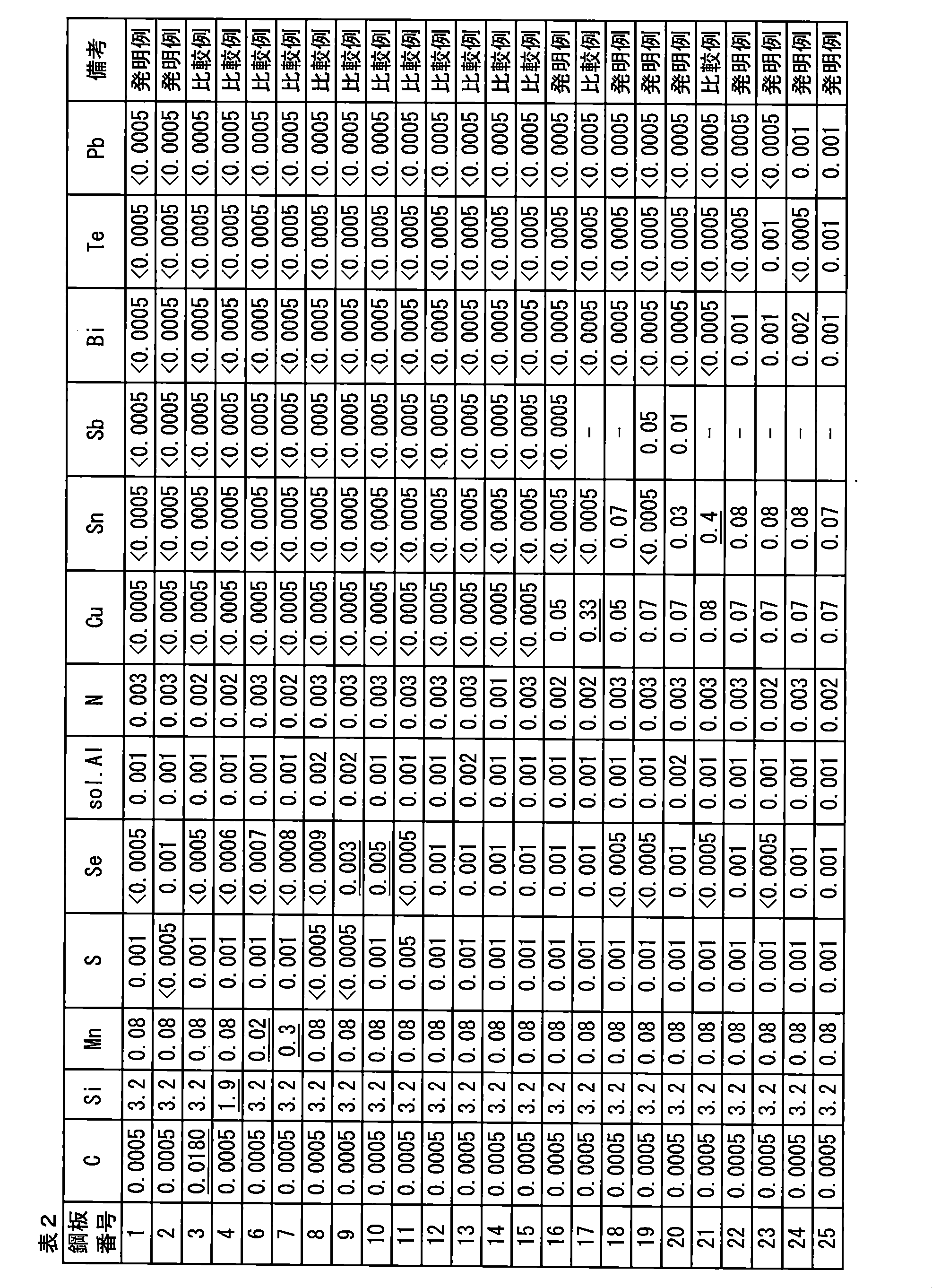
鋼板の成分が本発明の範囲内に入る鋼板番号1、2、16、18、19、20、22、23、24、25において、製造した方向性電磁鋼板の磁気特性及び一次被膜の密着性を、試験番号1~44として評価した。
各試験番号の方向性電磁鋼板から圧延方向長さ300mm×幅60mmのサンプルを採取し、800A/mで励磁し、磁束密度B8を求めた。また、コロイド状シリカ及びリン酸塩を主体とする絶縁被膜を焼き付けた後、最大磁束密度1.7T、周波数50Hzで励磁した時の鉄損W17/50を測定した。磁束密度B8が1.92T以上かつ、W17/50が0.85W/kg以下である方向性電磁鋼板を、磁気特性が優れるとした。なお、この基準値は、本実施例の鋼板の組成(主にはSi:3.25質量%)、及び厚さ(母鋼板が0.22mm)を考慮したものである。鋼板組成や板厚が異なれば、合否の基準値が異なることは言うまでもない。
各試験番号の方向性電磁鋼板から圧延方向長さ60mm×幅15mmのサンプルを採取し、10mmの曲率で曲げ試験を実施した。曲げ試験は、円筒型マンドレル屈曲試験機を用いて、円筒の軸方向がサンプルの幅方向と一致するようにサンプルに設置して実施した。曲げ試験後のサンプルの表面を観察し、加工領域剥離部の圧延方向の長さをエッジから1mmの幅方向位置から、1mmごとに13水準測定し、そのうちの最大の長さLSを特定した。そして、LSが、加工部全長L(約15.7mm)に占める割合を算出し、密着長さ百分率=(L-LS)/L×100(%)(一次被膜残存率)で密着性を評価して、90%以上が被膜密着性に優れるとした。
各試験番号の方向性電磁鋼板から圧延方向長さ10mm×幅10mmのサンプルを採取し、母材鋼板のみが溶解するよう電解液中で定電位電解して、一次被膜を剥離し、一次被膜の構造及び組成を調査した。剥離方法及び測定方法は前述の手段に従い、使用した電解液成分は、非水溶媒系の10%アセチルアセトン‐1%テトラメチルアンモニウムクロライドーメタノールであり、電解量は80C/cm2であった。最終的に以下の値を得た。
(1)Al濃化領域の数密度:D3
(2)嵌入酸化物層領域でありかつAl濃化領域である領域の面積:S5
(3)Al濃化領域の面積:S3
(4)嵌入酸化物層領域でありかつAl濃化領域である領域の、表面酸化物層と嵌入酸化物層の境界の基準値H0からの距離:H5
(5)嵌入酸化物層領域の面積:S1
(6)Y群元素の合計含有量
(7)Ca群元素の合計含有量
(8)Ca群濃化領域の数密度:D4
(9)観察面積:S0
水性スラリーの焼鈍分離剤の原料粉末を、前述の手段に従って測定し、以下の値を得た。
(11) (0.253[Y]+0.180[La]+0.170[Ce])/0.454[Mg]:CY
(12) (0.353[Ca]+0.252[Sr]+0.195[Ba])/0.454[Mg]:CC
(13) MgOの平均粒径:R1
(14) Ca群元素含有粒子の平均粒径:R2
(15) Ca群元素を含有する粒子の数密度≧250億個/cm3
脱炭焼鈍後の鋼板に塗布する水性スラリーを、MgO、Y群元素含有化合物及びCa群元素含有化合物を各群元素含有量が表3のようになるよう水と混合して調整した。この際、化合物種及び各群元素の含有量(CY、CC)を変化させた。
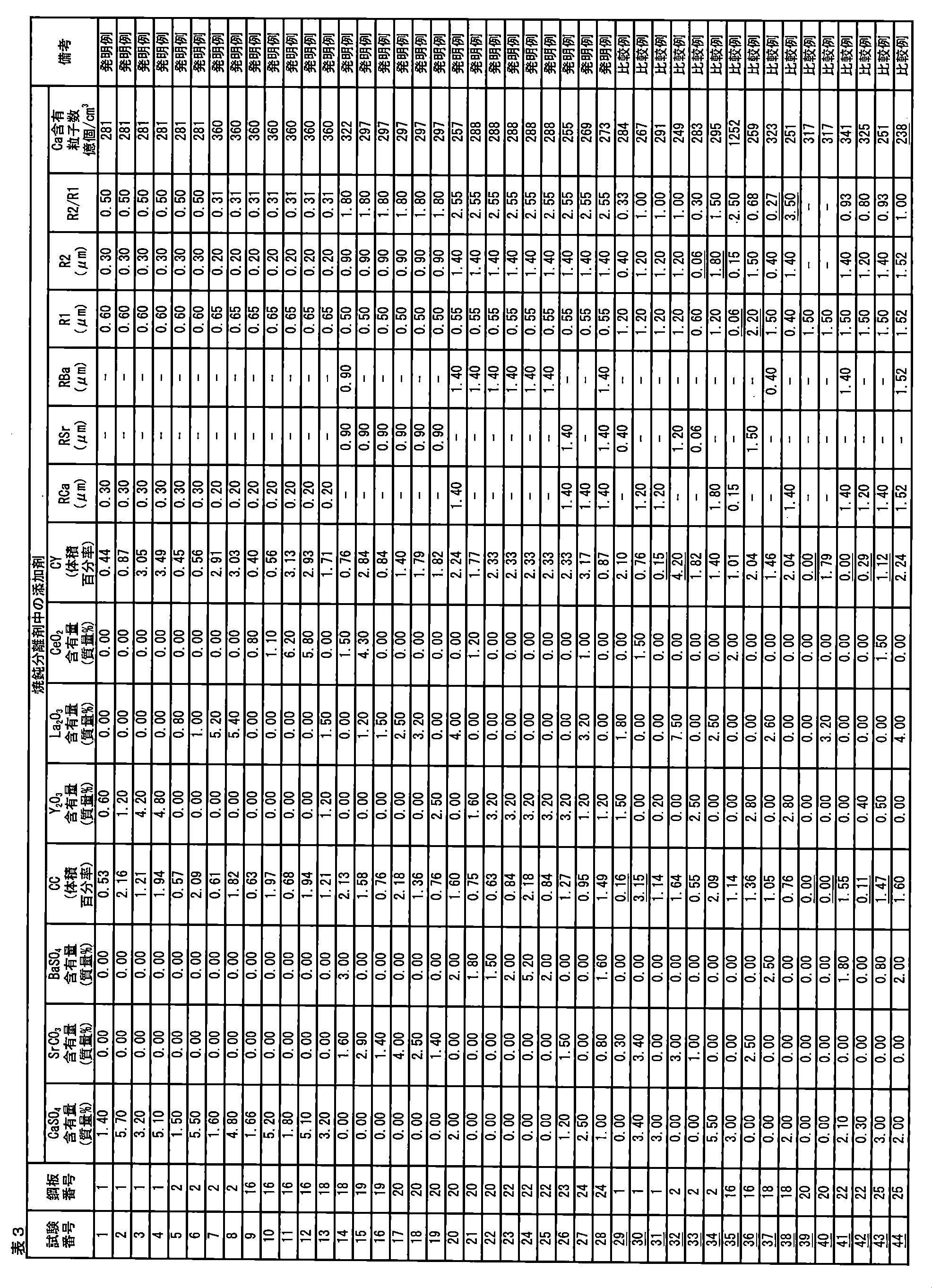
試験番号44では、原料粉末におけるCa群元素含有粒子の数密度が少なかった。その結果、S5が0.33未満となり、一次被膜残存率が78%と、被膜密着性が劣位であった。

脱炭焼鈍後の鋼板に塗布する水性スラリーを、MgO、Y群元素含有化合物、Ca群元素含有化合物及びTi群含有化合物を各群元素含有量が表5のようになるよう水と混合して調整した。この際、化合物種及び各群元素の含有量(CY、CC、CT)を変化させた。
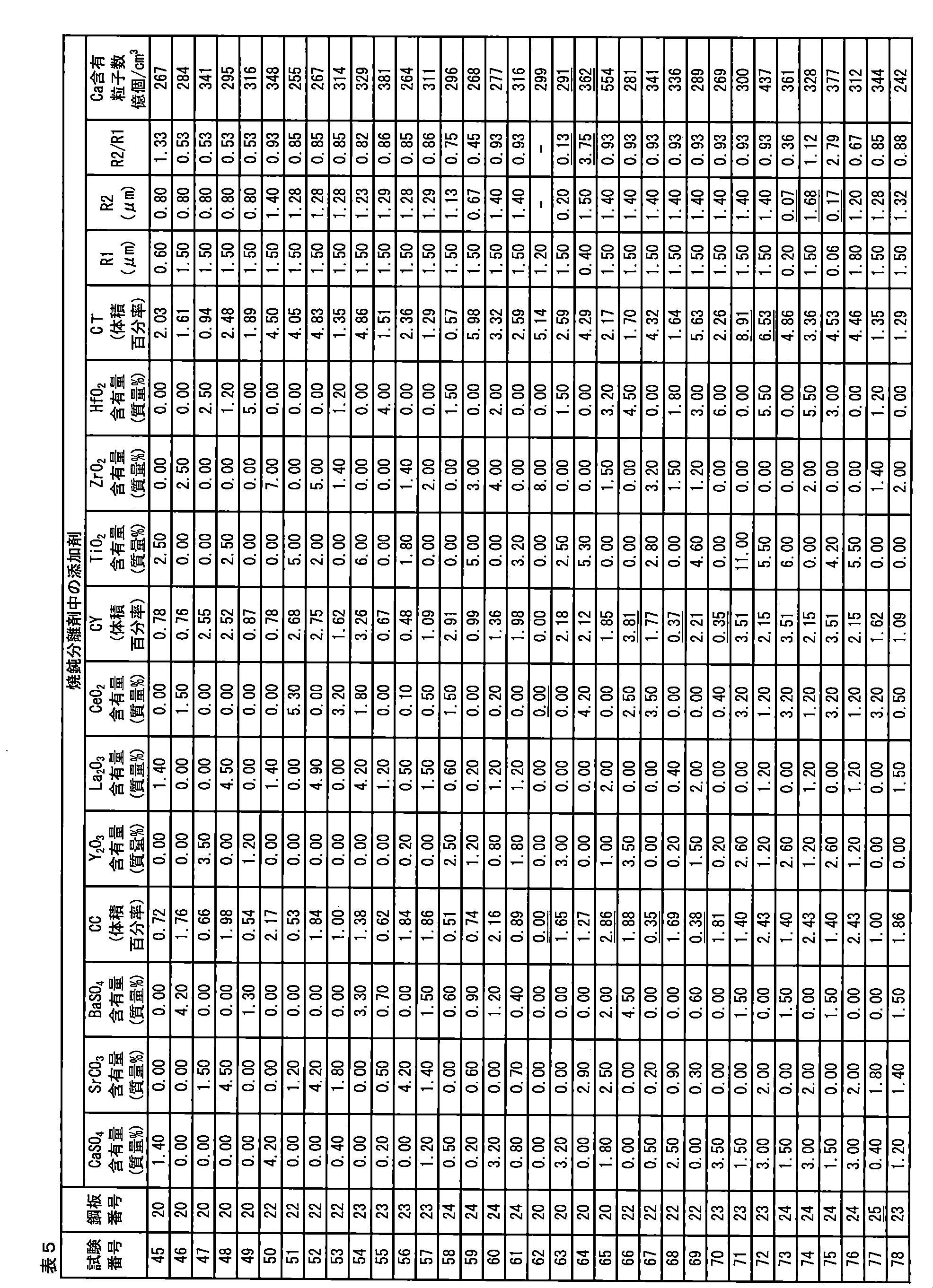
試験番号78では、Ca群元素含有粒子の数密度が低すぎた。その結果、S5が0.33未満となり、一次被膜残存率が84%と、被膜密着性が劣位であった。
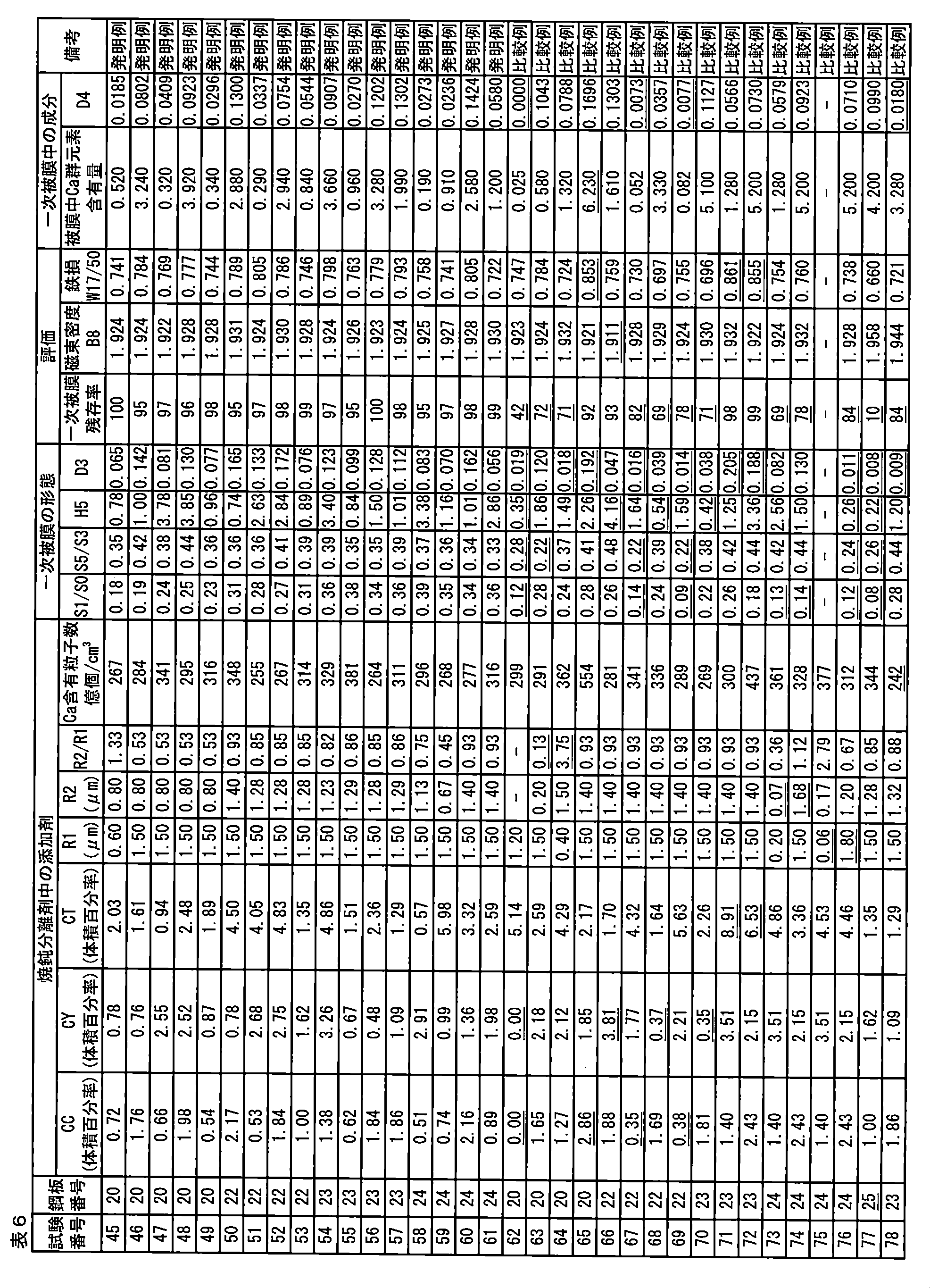
2 嵌入酸化物層
3 最深嵌入位置
A0 全ての観察領域
A1 嵌入酸化物領域
A2 表面酸化物層領域
A3 Al(アルミニウム)濃化領域
A4 Ca群元素濃化領域
A5 嵌入酸化物領域内に存在するAl(アルミニウム)濃化領域
Claims (11)
- 質量%で、
C:0.0050%以下、
Si:2.5~4.5%、
Mn:0.02~0.20%、
S及びSeからなる群から選択される1種以上の元素:合計で0.005%以下、
sol.Al:0.010%以下、及び
N:0.010%以下、
を含有し、残部はFe及び不純物からなる化学組成を有する母材鋼板と、
前記母材鋼板の表面上に形成されており、Mg2SiO4を主成分として含有する一次被膜とを備え、
前記母材鋼板の板厚方向において、前記一次被膜側から前記母材鋼板側に向かう方向を正としたときの前記母材鋼板側の前記一次被膜の表面の高さ及び前記一次被膜中の成分情報を鋼板表面に平行な面に投影して展開した特性X線強度及び高さ相関分布図において、
前記一次被膜の表面高さの中央値をH0として、H0+0.2μmより前記母材鋼板側に存在する前記一次被膜を「嵌入酸化物層領域」と、H0+0.2μmより前記一次被膜側に存在する前記一次被膜を「表面酸化物層領域」と規定し、かつ、
Alの特性X線強度の最大値を特定し、該Alの特性X線強度の最大値の20%以上のAlの特性X線強度が得られる領域を「Al濃化領域」としたとき、
前記一次被膜が、
(1) 前記Al濃化領域の数密度D3:0.020~0.180個/μm2、
(2) (前記嵌入酸化物層領域でありかつ前記Al濃化領域である領域の合計面積S5)/(前記Al濃化領域の合計面積S3)≧33%、
(3) 前記嵌入酸化物層領域でありかつ前記Al濃化領域である領域の板厚方向の高さの平均値からH0を引いた距離H5:0.4~4.0μm、
(4) (前記嵌入酸化物層領域の合計面積S1)/(観察面積S0)≧15%、
の条件を満足することを特徴とする方向性電磁鋼板。 - 前記一次被膜がY、La、Ceからなる群から選択される1種以上の元素、及び、Ca、Sr、Baからなる群から選択される1種以上の元素を含有し、かつ、
前記特性X線強度及び高さ相関分布図において、Ca、Sr、Baそれぞれの特性X線強度の最大値を特定し、前記Caの特性X線強度の最大値の20%以上のCaの特性X線強度が得られる領域と、前記Srの特性X線強度の最大値の20%以上のSrの特性X線強度が得られる領域と、前記Baの特性X線強度の最大値の20%以上のBaの特性X線強度が得られる領域とを合せて「Ca群元素濃化領域」としたとき、
前記一次被膜が
(5) 前記一次被膜中のMg2SiO4の含有量に対する、前記Y、La、Ceからなる群から選択される1種以上の元素の合計含有量の割合:0.1~6.0質量%、
(6) 前記一次被膜中のMg2SiO4の含有量に対する、前記Ca、Sr、Baからなる群から選択される1種以上の元素の合計含有量の割合:0.1~6.0質量%、
(7) 前記Ca群元素濃化領域の数密度D4:0.008個/μm2以上、
の条件を満足することを特徴とする、請求項1に記載の方向性電磁鋼板。 - MgOを主成分とする焼鈍分離剤であって、
Y、La、Ceからなる群から選択される1種以上の元素、及び、Ca、Sr、Baからなる群から選択される1種以上の元素を含有し、
前記MgOの含有量に対する、Mg、Y、La、Ce、Ca、Sr、Baの含有量の割合(質量%)をそれぞれ[Mg]、[Y]、[La]、[Ce]、[Ca]、[Sr]、[Ba]と表したとき、
(8) (0.253[Y]+0.180[La]+0.170[Ce])/0.454[Mg]:0.40~3.60、
(9) (0.353[Ca]+0.252[Sr]+0.195[Ba])/0.454[Mg]:0.20~2.20、
を満たし、
さらに、
(10) 前記MgOの平均粒径R1:0.08~1.50μm、
(11) 前記Ca群元素濃化領域における前記Ca、Sr、Baからなる群から選択される1種以上の元素を含有する粒子の平均粒径R2:0.08~1.50μm、
(12) (前記平均粒径R2)/(前記平均粒径R1):0.3~3.0、
(13) Ca群元素を含有する粒子の数密度≧250億個/cm3、
の条件を満足することを特徴とする焼鈍分離剤。 - 前記Y、La、Ceからなる群から選択される1種以上の元素を含有する粒子が、さらに酸素を含有することを特徴とする、請求項3に記載の焼鈍分離剤。
- Ti、Zr、Hfからなる群から選択される1種以上の元素をさらに含有することを特徴とする請求項3に記載の焼鈍分離剤。
- 質量%で、
C:0.100%以下、
Si:2.5~4.5%、
Mn:0.02~0.20%、
S及びSeからなる群から選択される1種以上の元素:合計で0.005~0.070%、
sol.Al:0.005~0.050%、及び、
N:0.001~0.030%、
を含有し、残部がFe及び不純物からなるスラブを熱間圧延して熱延鋼板を製造する工程と、
前記熱延鋼板に対して80%以上の冷延率で冷間圧延を実施して冷延鋼板を製造する工程と、
前記冷延鋼板に対して脱炭焼鈍を実施して脱炭焼鈍板を製造する工程と、
前記脱炭焼鈍板の表面に、水性スラリーを塗布し乾燥する工程と、
前記水性スラリーが乾燥された後の鋼板に対して仕上焼鈍を実施する工程とを備え、
前記水性スラリーが、前記請求項3~5のいずれか一項に記載の焼鈍分離剤を含むことを特徴とする、方向性電磁鋼板の製造方法。 - 前記Feの一部に代えて、さらにBi,Te及びPbからなる群から選択される1種以上の元素を、合計で0.030%以下含有する、請求項6に記載の方向性電磁鋼板の製造方法。
- 前記Feの一部に代えて、さらにCu、Sn及びSbからなる群から選択される1種以上の元素を、合計で0.60%以下含有する、請求項6または7に記載の方向性電磁鋼板の製造方法。
- 質量%で、
C:0.100%以下、
Si:2.5~4.5%、
Mn:0.02~0.20%、
S及びSeからなる群から選択される1種以上の元素:合計で0.005~0.070%、
sol.Al:0.005~0.050%、及び、
N:0.001~0.030%、
を含有し、残部がFe及び不純物からなるスラブを熱間圧延して熱延鋼板を製造する工程と、
前記熱延鋼板に対して80%以上の冷延率で冷間圧延を実施して冷延鋼板を製造する工程と、
前記冷延鋼板に対して脱炭焼鈍を実施して脱炭焼鈍板を製造する工程と、
前記脱炭焼鈍板の表面に、水性スラリーを塗布し乾燥する工程とを備え、
前記水性スラリーが、前記請求項3~5のいずれか一項に記載の焼鈍分離剤を含むことを特徴とする、方向性電磁鋼板を製造するための仕上焼鈍用鋼板の製造方法。 - 前記Feの一部に代えて、さらにBi,Te及びPbからなる群から選択される1種以上の元素を、合計で0.030%以下含有する、請求項9に記載の仕上げ焼鈍用鋼板の製造方法。
- 前記Feの一部に代えて、さらにCu、Sn及びSbからなる群から選択される1種以上の元素を、合計で0.60%以下含有する、請求項9または10に記載の仕上げ焼鈍用鋼板の製造方法。
Priority Applications (6)
| Application Number | Priority Date | Filing Date | Title |
|---|---|---|---|
| KR1020217020622A KR102489904B1 (ko) | 2019-01-08 | 2020-01-08 | 방향성 전자 강판, 어닐링 분리제 및 방향성 전자 강판의 제조 방법 |
| US17/421,215 US11634787B2 (en) | 2019-01-08 | 2020-01-08 | Grain-oriented electrical steel sheet, annealing separator, and method for manufacturing grain-oriented electrical steel sheet |
| CN202080008101.7A CN113260719B (zh) | 2019-01-08 | 2020-01-08 | 方向性电磁钢板、退火分离剂及方向性电磁钢板的制造方法 |
| JP2020565183A JP7184098B2 (ja) | 2019-01-08 | 2020-01-08 | 方向性電磁鋼板、焼鈍分離剤、及び方向性電磁鋼板の製造方法 |
| EP20738047.8A EP3910076A4 (en) | 2019-01-08 | 2020-01-08 | CORNORIENTED ELECTRIC STEEL SHEET, ANNEALING RELEASE AGENT AND PROCESS FOR THE PRODUCTION OF A CORNORIENTED MAGNETIC STEEL SHEET |
| BR112021012948-0A BR112021012948B1 (pt) | 2019-01-08 | 2020-01-08 | Chapa de aço elétrico de grão orientado, separador de recozimento, e, método para fabricar chapa de aço elétrico de grão orientado |
Applications Claiming Priority (2)
| Application Number | Priority Date | Filing Date | Title |
|---|---|---|---|
| JP2019001149 | 2019-01-08 | ||
| JP2019-001149 | 2019-01-08 |
Publications (1)
| Publication Number | Publication Date |
|---|---|
| WO2020145314A1 true WO2020145314A1 (ja) | 2020-07-16 |
Family
ID=71520483
Family Applications (1)
| Application Number | Title | Priority Date | Filing Date |
|---|---|---|---|
| PCT/JP2020/000338 Ceased WO2020145314A1 (ja) | 2019-01-08 | 2020-01-08 | 方向性電磁鋼板、焼鈍分離剤、及び方向性電磁鋼板の製造方法 |
Country Status (6)
| Country | Link |
|---|---|
| US (1) | US11634787B2 (ja) |
| EP (1) | EP3910076A4 (ja) |
| JP (1) | JP7184098B2 (ja) |
| KR (1) | KR102489904B1 (ja) |
| CN (1) | CN113260719B (ja) |
| WO (1) | WO2020145314A1 (ja) |
Families Citing this family (1)
| Publication number | Priority date | Publication date | Assignee | Title |
|---|---|---|---|---|
| US12454735B2 (en) * | 2019-01-08 | 2025-10-28 | Nippon Steel Corporation | Grain-oriented electrical steel sheet, finish annealing-use steel sheet, annealing separator, method for manufacturing grain-oriented electrical steel sheet, and method for manufacturing finish annealing-use steel sheet |
Citations (10)
| Publication number | Priority date | Publication date | Assignee | Title |
|---|---|---|---|---|
| JPH0688171A (ja) | 1992-09-09 | 1994-03-29 | Nippon Steel Corp | 超高磁束密度一方向性電磁鋼板の製造方法 |
| JPH06220539A (ja) * | 1993-01-21 | 1994-08-09 | Nippon Steel Corp | 磁区細分化一方向性電磁鋼板の製造法 |
| JPH08269552A (ja) | 1995-03-28 | 1996-10-15 | Nippon Steel Corp | 超高磁束密度一方向性電磁鋼板の製造方法 |
| JP2005290446A (ja) | 2004-03-31 | 2005-10-20 | Jfe Steel Kk | 磁気特性および被膜特性に優れる方向性電磁鋼板の製造方法 |
| WO2006126660A1 (ja) * | 2005-05-23 | 2006-11-30 | Nippon Steel Corporation | 被膜密着性に優れる方向性電磁鋼板およびその製造方法 |
| WO2008062853A1 (en) * | 2006-11-22 | 2008-05-29 | Nippon Steel Corporation | Unidirectionally grain oriented electromagnetic steel sheet having excellent film adhesion, and method for manufacturing the same |
| JP2008127634A (ja) | 2006-11-21 | 2008-06-05 | Nippon Steel Corp | 一方向性電磁鋼板の製造方法 |
| JP2017133072A (ja) * | 2016-01-28 | 2017-08-03 | 新日鐵住金株式会社 | 皮膜密着性及び耐錆性の優れた一方向性電磁鋼板、一方向性電磁鋼板用原板及びそれらの製造方法 |
| JP2018066061A (ja) * | 2016-10-18 | 2018-04-26 | Jfeスチール株式会社 | 方向性電磁鋼板およびその製造方法 |
| WO2018117673A1 (ko) * | 2016-12-22 | 2018-06-28 | 주식회사 포스코 | 방향성 전기강판용 소둔 분리제 조성물, 방향성 전기강판 및 방향성 전기강판의 제조방법 |
Family Cites Families (12)
| Publication number | Priority date | Publication date | Assignee | Title |
|---|---|---|---|---|
| JP4747564B2 (ja) * | 2004-11-30 | 2011-08-17 | Jfeスチール株式会社 | 方向性電磁鋼板 |
| KR101677883B1 (ko) * | 2013-09-19 | 2016-11-18 | 제이에프이 스틸 가부시키가이샤 | 방향성 전기 강판 및 그 제조 방법 |
| WO2015174362A1 (ja) | 2014-05-12 | 2015-11-19 | Jfeスチール株式会社 | 方向性電磁鋼板の製造方法 |
| KR101693516B1 (ko) * | 2014-12-24 | 2017-01-06 | 주식회사 포스코 | 방향성 전기강판 및 그 제조방법 |
| WO2016105053A1 (ko) * | 2014-12-24 | 2016-06-30 | 주식회사 포스코 | 방향성 전기강판 및 그 제조방법 |
| JP6350398B2 (ja) | 2015-06-09 | 2018-07-04 | Jfeスチール株式会社 | 方向性電磁鋼板およびその製造方法 |
| US10907234B2 (en) * | 2015-10-26 | 2021-02-02 | Nippon Steel Corporation | Grain-oriented electrical steel sheet and decarburized steel sheet used for manufacturing the same |
| CA3004286C (en) * | 2015-12-04 | 2021-05-04 | Jfe Steel Corporation | Method of producing grain-oriented electrical steel sheet |
| KR101762341B1 (ko) * | 2015-12-18 | 2017-07-27 | 주식회사 포스코 | 방향성 전기강판용 소둔분리제, 방향성 전기강판, 및 방향성 전기강판의 제조 방법 |
| JP2017113072A (ja) * | 2015-12-21 | 2017-06-29 | 株式会社藤商事 | 遊技機 |
| KR101850133B1 (ko) | 2016-10-26 | 2018-04-19 | 주식회사 포스코 | 방향성 전기강판용 소둔 분리제 조성물, 방향성 전기강판 및 방향성 전기강판의 제조방법 |
| EP3533902B1 (en) * | 2016-12-21 | 2021-02-17 | JFE Steel Corporation | Grain-oriented electrical steel sheet and production method for grain-oriented electrical steel sheet |
-
2020
- 2020-01-08 EP EP20738047.8A patent/EP3910076A4/en active Pending
- 2020-01-08 JP JP2020565183A patent/JP7184098B2/ja active Active
- 2020-01-08 CN CN202080008101.7A patent/CN113260719B/zh active Active
- 2020-01-08 KR KR1020217020622A patent/KR102489904B1/ko active Active
- 2020-01-08 US US17/421,215 patent/US11634787B2/en active Active
- 2020-01-08 WO PCT/JP2020/000338 patent/WO2020145314A1/ja not_active Ceased
Patent Citations (11)
| Publication number | Priority date | Publication date | Assignee | Title |
|---|---|---|---|---|
| JPH0688171A (ja) | 1992-09-09 | 1994-03-29 | Nippon Steel Corp | 超高磁束密度一方向性電磁鋼板の製造方法 |
| JPH06220539A (ja) * | 1993-01-21 | 1994-08-09 | Nippon Steel Corp | 磁区細分化一方向性電磁鋼板の製造法 |
| JPH08269552A (ja) | 1995-03-28 | 1996-10-15 | Nippon Steel Corp | 超高磁束密度一方向性電磁鋼板の製造方法 |
| JP2005290446A (ja) | 2004-03-31 | 2005-10-20 | Jfe Steel Kk | 磁気特性および被膜特性に優れる方向性電磁鋼板の製造方法 |
| WO2006126660A1 (ja) * | 2005-05-23 | 2006-11-30 | Nippon Steel Corporation | 被膜密着性に優れる方向性電磁鋼板およびその製造方法 |
| JP2012214902A (ja) | 2005-05-23 | 2012-11-08 | Nippon Steel Corp | 被膜密着性に優れる方向性電磁鋼板およびその製造方法 |
| JP2008127634A (ja) | 2006-11-21 | 2008-06-05 | Nippon Steel Corp | 一方向性電磁鋼板の製造方法 |
| WO2008062853A1 (en) * | 2006-11-22 | 2008-05-29 | Nippon Steel Corporation | Unidirectionally grain oriented electromagnetic steel sheet having excellent film adhesion, and method for manufacturing the same |
| JP2017133072A (ja) * | 2016-01-28 | 2017-08-03 | 新日鐵住金株式会社 | 皮膜密着性及び耐錆性の優れた一方向性電磁鋼板、一方向性電磁鋼板用原板及びそれらの製造方法 |
| JP2018066061A (ja) * | 2016-10-18 | 2018-04-26 | Jfeスチール株式会社 | 方向性電磁鋼板およびその製造方法 |
| WO2018117673A1 (ko) * | 2016-12-22 | 2018-06-28 | 주식회사 포스코 | 방향성 전기강판용 소둔 분리제 조성물, 방향성 전기강판 및 방향성 전기강판의 제조방법 |
Non-Patent Citations (1)
| Title |
|---|
| See also references of EP3910076A4 |
Also Published As
| Publication number | Publication date |
|---|---|
| CN113260719B (zh) | 2023-01-20 |
| BR112021012948A2 (pt) | 2021-09-14 |
| KR20210096239A (ko) | 2021-08-04 |
| CN113260719A (zh) | 2021-08-13 |
| KR102489904B1 (ko) | 2023-01-18 |
| EP3910076A4 (en) | 2022-09-28 |
| EP3910076A1 (en) | 2021-11-17 |
| US20220064753A1 (en) | 2022-03-03 |
| US11634787B2 (en) | 2023-04-25 |
| JPWO2020145314A1 (ja) | 2021-11-04 |
| JP7184098B2 (ja) | 2022-12-06 |
Similar Documents
| Publication | Publication Date | Title |
|---|---|---|
| KR101165430B1 (ko) | 피막 밀착성이 우수한 일방향성 전자 강판 및 그 제조법 | |
| RU2768905C1 (ru) | Способ производства листа электротехнической стали с ориентированной зеренной структурой | |
| WO2020145319A1 (ja) | 方向性電磁鋼板の製造方法および方向性電磁鋼板 | |
| JP7184098B2 (ja) | 方向性電磁鋼板、焼鈍分離剤、及び方向性電磁鋼板の製造方法 | |
| CN113260718B (zh) | 方向性电磁钢板、方向性电磁钢板的制造方法及方向性电磁钢板的制造中利用的退火分离剂 | |
| JP7180691B2 (ja) | 方向性電磁鋼板、仕上焼鈍用鋼板、焼鈍分離剤、方向性電磁鋼板の製造方法、及び仕上焼鈍用鋼板の製造方法 | |
| JP7464818B2 (ja) | 方向性電磁鋼板の製造方法および方向性電磁鋼板、ならびに焼鈍分離剤 | |
| US12454735B2 (en) | Grain-oriented electrical steel sheet, finish annealing-use steel sheet, annealing separator, method for manufacturing grain-oriented electrical steel sheet, and method for manufacturing finish annealing-use steel sheet | |
| JP7205555B2 (ja) | 方向性電磁鋼板およびその製造方法、ならびに焼鈍分離剤 | |
| RU2792912C2 (ru) | Лист электротехнической стали с ориентированной зеренной структурой, стальной лист, используемый для финишного отжига, отжиговый сепаратор, способ изготовления листа электротехнической стали с ориентированной зеренной структурой и способ изготовления стального листа, используемого для финишного отжига | |
| RU2773042C1 (ru) | Лист анизотропной электротехнической стали, сепаратор отжига и способ производства листа анизотропной электротехнической стали | |
| RU2777398C1 (ru) | Лист электротехнической стали с ориентированной зеренной структурой, стальной лист, используемый для финишного отжига, отжиговый сепаратор, способ изготовления листа электротехнической стали с ориентированной зеренной структурой и способ изготовления стального листа, используемого для финишного отжига | |
| CN112771183B (zh) | 方向性电磁钢板、方向性电磁钢板的制造方法及方向性电磁钢板的制造中利用的退火分离剂 | |
| JP7837135B2 (ja) | 方向性電磁鋼板、および方向性電磁鋼板の製造方法、ならびに焼鈍分離剤 | |
| JP2021123766A (ja) | 方向性電磁鋼板、および方向性電磁鋼板の製造方法、ならびに焼鈍分離剤 | |
| WO2020145321A1 (ja) | 方向性電磁鋼板、方向性電磁鋼板の製造方法、及び、方向性電磁鋼板の製造に利用される焼鈍分離剤 | |
| JP2021123768A (ja) | 方向性電磁鋼板の製造方法および方向性電磁鋼板、ならびに焼鈍分離剤 |
Legal Events
| Date | Code | Title | Description |
|---|---|---|---|
| 121 | Ep: the epo has been informed by wipo that ep was designated in this application |
Ref document number: 20738047 Country of ref document: EP Kind code of ref document: A1 |
|
| ENP | Entry into the national phase |
Ref document number: 2020565183 Country of ref document: JP Kind code of ref document: A |
|
| ENP | Entry into the national phase |
Ref document number: 20217020622 Country of ref document: KR Kind code of ref document: A |
|
| REG | Reference to national code |
Ref country code: BR Ref legal event code: B01A Ref document number: 112021012948 Country of ref document: BR |
|
| NENP | Non-entry into the national phase |
Ref country code: DE |
|
| ENP | Entry into the national phase |
Ref document number: 2020738047 Country of ref document: EP Effective date: 20210809 |
|
| ENP | Entry into the national phase |
Ref document number: 112021012948 Country of ref document: BR Kind code of ref document: A2 Effective date: 20210629 |