WO2020152928A1 - Système de cathéter à ballonnet et procédé pour photothérapie de tumeurs - Google Patents
Système de cathéter à ballonnet et procédé pour photothérapie de tumeurs Download PDFInfo
- Publication number
- WO2020152928A1 WO2020152928A1 PCT/JP2019/041172 JP2019041172W WO2020152928A1 WO 2020152928 A1 WO2020152928 A1 WO 2020152928A1 JP 2019041172 W JP2019041172 W JP 2019041172W WO 2020152928 A1 WO2020152928 A1 WO 2020152928A1
- Authority
- WO
- WIPO (PCT)
- Prior art keywords
- balloon
- wall
- light irradiation
- liquid
- probe
- Prior art date
- Legal status (The legal status is an assumption and is not a legal conclusion. Google has not performed a legal analysis and makes no representation as to the accuracy of the status listed.)
- Ceased
Links
Images


Classifications
-
- A—HUMAN NECESSITIES
- A61—MEDICAL OR VETERINARY SCIENCE; HYGIENE
- A61N—ELECTROTHERAPY; MAGNETOTHERAPY; RADIATION THERAPY; ULTRASOUND THERAPY
- A61N5/00—Radiation therapy
- A61N5/06—Radiation therapy using light
- A61N5/0601—Apparatus for use inside the body
- A61N5/0603—Apparatus for use inside the body for treatment of body cavities
-
- A—HUMAN NECESSITIES
- A61—MEDICAL OR VETERINARY SCIENCE; HYGIENE
- A61M—DEVICES FOR INTRODUCING MEDIA INTO, OR ONTO, THE BODY; DEVICES FOR TRANSDUCING BODY MEDIA OR FOR TAKING MEDIA FROM THE BODY; DEVICES FOR PRODUCING OR ENDING SLEEP OR STUPOR
- A61M25/00—Catheters; Hollow probes
- A61M25/10—Balloon catheters
- A61M25/1018—Balloon inflating or inflation-control devices
- A61M25/10181—Means for forcing inflation fluid into the balloon
-
- A—HUMAN NECESSITIES
- A61—MEDICAL OR VETERINARY SCIENCE; HYGIENE
- A61M—DEVICES FOR INTRODUCING MEDIA INTO, OR ONTO, THE BODY; DEVICES FOR TRANSDUCING BODY MEDIA OR FOR TAKING MEDIA FROM THE BODY; DEVICES FOR PRODUCING OR ENDING SLEEP OR STUPOR
- A61M25/00—Catheters; Hollow probes
- A61M25/10—Balloon catheters
- A61M25/104—Balloon catheters used for angioplasty
-
- A—HUMAN NECESSITIES
- A61—MEDICAL OR VETERINARY SCIENCE; HYGIENE
- A61N—ELECTROTHERAPY; MAGNETOTHERAPY; RADIATION THERAPY; ULTRASOUND THERAPY
- A61N5/00—Radiation therapy
- A61N5/06—Radiation therapy using light
- A61N5/0613—Apparatus adapted for a specific treatment
- A61N5/062—Photodynamic therapy, i.e. excitation of an agent
-
- A—HUMAN NECESSITIES
- A61—MEDICAL OR VETERINARY SCIENCE; HYGIENE
- A61N—ELECTROTHERAPY; MAGNETOTHERAPY; RADIATION THERAPY; ULTRASOUND THERAPY
- A61N5/00—Radiation therapy
- A61N5/10—X-ray therapy; Gamma-ray therapy; Particle-irradiation therapy
- A61N5/1001—X-ray therapy; Gamma-ray therapy; Particle-irradiation therapy using radiation sources introduced into or applied onto the body; brachytherapy
- A61N5/1002—Intraluminal radiation therapy
-
- A—HUMAN NECESSITIES
- A61—MEDICAL OR VETERINARY SCIENCE; HYGIENE
- A61N—ELECTROTHERAPY; MAGNETOTHERAPY; RADIATION THERAPY; ULTRASOUND THERAPY
- A61N5/00—Radiation therapy
- A61N5/10—X-ray therapy; Gamma-ray therapy; Particle-irradiation therapy
- A61N5/1001—X-ray therapy; Gamma-ray therapy; Particle-irradiation therapy using radiation sources introduced into or applied onto the body; brachytherapy
- A61N5/1007—Arrangements or means for the introduction of sources into the body
-
- A—HUMAN NECESSITIES
- A61—MEDICAL OR VETERINARY SCIENCE; HYGIENE
- A61B—DIAGNOSIS; SURGERY; IDENTIFICATION
- A61B18/00—Surgical instruments, devices or methods for transferring non-mechanical forms of energy to or from the body
- A61B2018/00053—Mechanical features of the instrument of device
- A61B2018/00214—Expandable means emitting energy, e.g. by elements carried thereon
- A61B2018/0022—Balloons
-
- A—HUMAN NECESSITIES
- A61—MEDICAL OR VETERINARY SCIENCE; HYGIENE
- A61B—DIAGNOSIS; SURGERY; IDENTIFICATION
- A61B18/00—Surgical instruments, devices or methods for transferring non-mechanical forms of energy to or from the body
- A61B2018/00315—Surgical instruments, devices or methods for transferring non-mechanical forms of energy to or from the body for treatment of particular body parts
- A61B2018/00505—Urinary tract
- A61B2018/00517—Urinary bladder or urethra
-
- A—HUMAN NECESSITIES
- A61—MEDICAL OR VETERINARY SCIENCE; HYGIENE
- A61B—DIAGNOSIS; SURGERY; IDENTIFICATION
- A61B18/00—Surgical instruments, devices or methods for transferring non-mechanical forms of energy to or from the body
- A61B18/18—Surgical instruments, devices or methods for transferring non-mechanical forms of energy to or from the body by applying electromagnetic radiation, e.g. microwaves
- A61B18/20—Surgical instruments, devices or methods for transferring non-mechanical forms of energy to or from the body by applying electromagnetic radiation, e.g. microwaves using laser
- A61B18/22—Surgical instruments, devices or methods for transferring non-mechanical forms of energy to or from the body by applying electromagnetic radiation, e.g. microwaves using laser the beam being directed along or through a flexible conduit, e.g. an optical fibre; Couplings or hand-pieces therefor
- A61B2018/2255—Optical elements at the distal end of probe tips
- A61B2018/2261—Optical elements at the distal end of probe tips with scattering, diffusion or dispersion of light
-
- A—HUMAN NECESSITIES
- A61—MEDICAL OR VETERINARY SCIENCE; HYGIENE
- A61M—DEVICES FOR INTRODUCING MEDIA INTO, OR ONTO, THE BODY; DEVICES FOR TRANSDUCING BODY MEDIA OR FOR TAKING MEDIA FROM THE BODY; DEVICES FOR PRODUCING OR ENDING SLEEP OR STUPOR
- A61M25/00—Catheters; Hollow probes
- A61M25/10—Balloon catheters
- A61M2025/1043—Balloon catheters with special features or adapted for special applications
- A61M2025/1088—Balloon catheters with special features or adapted for special applications having special surface characteristics depending on material properties or added substances, e.g. for reducing friction
-
- A—HUMAN NECESSITIES
- A61—MEDICAL OR VETERINARY SCIENCE; HYGIENE
- A61M—DEVICES FOR INTRODUCING MEDIA INTO, OR ONTO, THE BODY; DEVICES FOR TRANSDUCING BODY MEDIA OR FOR TAKING MEDIA FROM THE BODY; DEVICES FOR PRODUCING OR ENDING SLEEP OR STUPOR
- A61M25/00—Catheters; Hollow probes
- A61M25/10—Balloon catheters
- A61M25/1002—Balloon catheters characterised by balloon shape
-
- A—HUMAN NECESSITIES
- A61—MEDICAL OR VETERINARY SCIENCE; HYGIENE
- A61M—DEVICES FOR INTRODUCING MEDIA INTO, OR ONTO, THE BODY; DEVICES FOR TRANSDUCING BODY MEDIA OR FOR TAKING MEDIA FROM THE BODY; DEVICES FOR PRODUCING OR ENDING SLEEP OR STUPOR
- A61M25/00—Catheters; Hollow probes
- A61M25/10—Balloon catheters
- A61M25/1018—Balloon inflating or inflation-control devices
- A61M25/10181—Means for forcing inflation fluid into the balloon
- A61M25/10182—Injector syringes
-
- A—HUMAN NECESSITIES
- A61—MEDICAL OR VETERINARY SCIENCE; HYGIENE
- A61N—ELECTROTHERAPY; MAGNETOTHERAPY; RADIATION THERAPY; ULTRASOUND THERAPY
- A61N5/00—Radiation therapy
- A61N5/06—Radiation therapy using light
- A61N5/0601—Apparatus for use inside the body
- A61N5/0603—Apparatus for use inside the body for treatment of body cavities
- A61N2005/061—Bladder and/or urethra
-
- A—HUMAN NECESSITIES
- A61—MEDICAL OR VETERINARY SCIENCE; HYGIENE
- A61N—ELECTROTHERAPY; MAGNETOTHERAPY; RADIATION THERAPY; ULTRASOUND THERAPY
- A61N5/00—Radiation therapy
- A61N5/06—Radiation therapy using light
- A61N2005/063—Radiation therapy using light comprising light transmitting means, e.g. optical fibres
-
- A—HUMAN NECESSITIES
- A61—MEDICAL OR VETERINARY SCIENCE; HYGIENE
- A61N—ELECTROTHERAPY; MAGNETOTHERAPY; RADIATION THERAPY; ULTRASOUND THERAPY
- A61N5/00—Radiation therapy
- A61N5/10—X-ray therapy; Gamma-ray therapy; Particle-irradiation therapy
- A61N5/1001—X-ray therapy; Gamma-ray therapy; Particle-irradiation therapy using radiation sources introduced into or applied onto the body; brachytherapy
- A61N5/1002—Intraluminal radiation therapy
- A61N2005/1003—Intraluminal radiation therapy having means for centering a radioactive source within the lumen, e.g. balloons
Definitions
- the present invention relates to a balloon catheter system and an optical tumor treatment method of irradiating light energy through a balloon of a balloon catheter.
- the lesion is excised during surgical operation.
- a perfusate is flowed into the bladder to excise a lesion while excising a lesion while ensuring a field of view of the endoscope. Will be collected.
- the bladder is inflated by the perfusate, and its shape changes depending on its internal volume.
- Urological endoscopic surgery technique chart-For independence of transurethral surgery (Non-patent Document 1), page 108, in a state in which the bladder is filled with 300 ml or more of perfusate in TUR-Bt. It states that the wall of the bladder becomes thin and tension is applied, and that damage is likely to occur when energization for excision is performed in this state.
- Non-patent Document 2 Journal of Applied Clinical Medical Physics, Vol.8, No1, p55-68, Winter2007 (Non-patent Document 2), there is a reported example that the bladder size immediately after urination is 118 ml on average.
- optical treatment methods such as PDT (photodynamic therapy) or PIT (Photoimmuno Therapy) have been studied as effective treatment methods for cancer.
- US patent US6364874 describes Device for irradiating internal cavities of the body.
- the device of US Pat. No. 6,364,874 includes a flexible catheter made of a transparent material, an optical fiber designed to radially diffuse light coming from a light source, one end of the catheter enclosing a diffusing portion of the optical fiber. Including an inflatable balloon secured with.
- FIG. 1 of US Pat. No. 6,364,874 shows an instrument for irradiating a patient's bronchus
- FIG. 2 of US Pat. No. 6,364,874 shows an instrument for irradiating the uterus of a patient.
- the present invention has been made in view of the above circumstances, and an object thereof is to provide a balloon catheter and an optical tumor capable of maintaining a constant flow rate of perfusion when extending the mucosa of a treatment site. It is to realize the treatment method.
- a balloon catheter system includes a light irradiation probe having a light irradiation unit for irradiating light to the tip of a fiber probe, and the light irradiation probe can be inserted, and the light irradiation probe is arranged and sent.
- a balloon catheter provided with a shaft having a through hole through which a liquid is possible, and a balloon fixed to one end of the shaft and expandable and contractible by a liquid injected through the through hole of the shaft;
- An injection device comprising a measuring unit capable of measuring the amount of the liquid injected into the balloon, and an injection unit for injecting the liquid measured by the measuring unit into the balloon through the through hole.
- the balloon is inflated by the liquid injected into the balloon to extend the wall of the treatment site and keeps the wall of the treatment site extended by the inflated balloon.
- An optical tumor treatment method includes a balloon positioning step in which a balloon fixed to one end of a shaft of a balloon catheter positions in the bladder, and an injection part of an injection device is operated to move the liquid to the shaft.
- FIG. 6 is a diagram illustrating a state in which the tactile sensor provided on the outer surface of the balloon is in contact with the mucous membrane of the wall during the mucous membrane extension step.
- the figure explaining the balloon which provided two tactile sensors on the outer surface.
- FIG. 6 is a diagram illustrating a step of positioning a balloon fixed to one end of a shaft on which an imaging probe is arranged in a bladder.
- the figure explaining the step of positioning the balloon fixed to the shaft inserted in the treatment instrument channel in the bladder Diagram illustrating the state in which the outer surface of the balloon is in close contact with the bladder wall due to the mucous membrane extension step
- Reference numeral 1 in FIG. 1 is a balloon catheter system.
- the balloon catheter system 1 is, for example, an optical treatment device suitable for optical tumor treatment such as PIT.
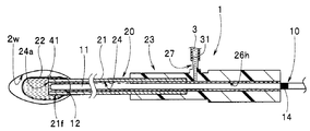
- the balloon catheter system 1 includes a light irradiation probe 10, a balloon catheter 20, and an injection device 30.
- the light irradiation probe 10 includes a light irradiation unit 12 at a probe tip 11f, which is one end of the elongated fiber probe 11.
- the light irradiation unit 12 is a light irradiation body having a light diffusion function.
- the light irradiation unit 12 includes an irradiation unit side peripheral surface 12s and an irradiation unit front end surface 12g.
- the outer surface of the irradiation unit side peripheral surface 12s has an annular shape.
- the outer surface of the front end surface 12g of the irradiation portion is hemispherical.
- the probe base end 11r which is the opposite side of the fiber probe 11 from the probe tip 11f, is the light source connection 13.
- the light source connection unit 13 is connected to a light source device (not shown).
- the light source device includes a light emitter (not shown). The light emitted from the light emitter is incident on a predetermined portion of the light source connecting portion 13, for example, the base end face 13r. The incident light is transmitted through the fiber probe 11 and is radially (omnidirectionally) emitted from the light irradiation unit 12.
- light is radially emitted to the fiber probe central axis a11 on the irradiation unit side peripheral surface 12s.
- the light is emitted radially toward the center point c12 on the front surface 12g of the irradiation portion.
- the balloon catheter 20 has a shaft 21 and a balloon 22.
- Reference numeral 23 is a port, which is provided at the end of the shaft 21.
- the shaft 21 is an elongated single-lumen tube that is transparent.
- the shaft 21 has one through hole 24 along the shaft axis a21.
- the shaft 21 is made of nylon, silicon, or Teflon (registered trademark).
- the inner diameter of the through hole 24 provided in the shaft 21 is set to be larger than the outer diameter of the fiber probe 11 by a predetermined dimension. Therefore, the fiber probe 11 can be inserted into the through hole 24.
- Reference numeral 24a is an opening for a balloon, which is an opening on the tip side of the through hole 24.
- a base end side opening opposite to the balloon opening 24a is a port opening 24b.
- the balloon 22 has translucency and elasticity.
- the balloon 22 is a bag having an opening on one side, and the opening-side end 22a is a balloon fixing portion.
- the opening-side end portion 22a of the balloon 22 is fixed to a predetermined position on the outer peripheral surface of the shaft distal end portion 21f of the shaft 21 while maintaining liquid tightness (water tightness) by welding or bonding.
- the balloon 22 is inflated by injecting the liquid into the balloon 22 from the balloon opening 24 a through the through hole 24 of the shaft 21.
- the balloon 22 has a substantially spherical expanded shape, and is formed so as to expand from the side opposite to the opening side end 22a. Further, the expanded balloon 22 contracts as the liquid in the balloon 22 is discharged through the through hole 24.
- the port 23 has a shaft fixing hole 25, a probe port portion 26, and a liquid port portion 27.
- a shaft base end portion 21r located on the opposite side of the shaft front end portion 21f is arranged.
- the shaft base end portion 21r is water-tightly fixed in the shaft fixing hole 25 by welding, adhesion, or the like.
- the probe port 26 is provided on the base end side of the port 23.
- the liquid port portion 27 is provided so as to project from the side portion of the port 23.
- the probe port 26 is provided with a probe insertion hole 26h.
- the insertion hole axis a26 of the probe insertion hole 26h coincides with the shaft axis a21 of the shaft 21.
- the inner diameter of the probe insertion hole 26h is equal to the inner diameter of the through hole 24 so that the fiber probe 11 can be inserted therethrough.
- the fiber probe 11 is designed to be inserted into the probe insertion hole 26h from the opening 26m of the base end surface 26e of the probe port portion 26 as shown by an arrow Y1. Then, the fiber probe 11 is introduced into the through hole 24 of the shaft 21 after passing through the probe insertion hole 26h.
- a holding portion (not shown) is provided on the opening 26m side of the probe port portion 26.
- the holding portion has a function of a sealing cock that prevents the liquid supplied into the balloon 22 and the through hole 24 from leaking to the outside, and a function of holding the arrangement position of the fiber probe 11.
- the liquid port portion 27 is provided with a liquid hole 27h.
- a liquid feeding tube 31 extending from the injection device 30 is detachably connected to the liquid port portion 27.
- the injection device 30 is a so-called syringe including a syringe 32 and a plunger 33.
- the liquid hole axis a27 of the liquid hole 27h intersects the shaft axis a21 at a predetermined angle ⁇ .
- the liquid hole axis a27 in the present embodiment is orthogonal to the shaft axis a21.
- the liquid port shaft a27 may intersect the shaft shaft a21 at an angle, and may extend from the side portion in the proximal direction. Further, the syringe 32 may be directly attached to the liquid port portion 27. In this case, the liquid port portion 27 serves as a syringe mounting portion on which the syringe 32 can be freely attached and detached.
- the syringe 32 is a cylinder having a liquid storage space 32S.
- the plunger 33 is arranged so as to be movable back and forth in the liquid storage space 32S and to prevent the liquid from leaking out from the liquid storage space 32S.
- the liquid stored in the liquid storage space 32S passes through the liquid hole 27h and the through hole 24 in accordance with the operation of the plunger 33 that functions as an injection portion, and is injected into the balloon 22 from the balloon opening 24a. ..
- the syringe 32 has a plurality of scales and functions as a measuring unit.
- the syringe 32 is provided with scales s1, s2, and s3, for example.
- the first scale s1 is a scale that notifies the user of the amount of liquid stored in the syringe 32 in advance.
- the second scale s2 is a scale that defines the lower limit when injecting the liquid stored in the syringe 32 into the balloon 22.
- the third scale s3 is a scale that defines the upper limit when injecting the liquid stored in the syringe 32 into the balloon 22.
- Reference numeral 40 is a contact detection unit, and the contact detection unit 40 detects that the outer surface of the balloon 22 contacts the wall of the treatment site.
- the contact detection unit 40 includes a tactile sensor 41 having a function of detecting pressure, reflection of light, change in capacitance between electrodes, and the like, and a signal line 42 extending from the tactile sensor 41.
- a detection signal is output through the signal line 42 and, for example, a buzzer (not shown) sounds.
- a buzzer not shown
- the detection signal may be wirelessly output from the tactile sensor 41.
- the tactile sensor 41 is fixed to a predetermined position on the outer surface of the balloon 22.
- the signal line 42 extends from the tactile sensor 41 and is arranged on the outer surface of the shaft 21 and the port 23 along the shaft axis a21 and the insertion hole axis a26.
- the signal line 42 extends from, for example, a side portion of the port 23 on the base end side.
- the injection device 30 is a syringe including a syringe 32 and a plunger 33.
- the injection device 30 may be, for example, a pump type fluid supply device (not shown).
- a pump (not shown) is driven by the operation of a pump drive switch (not shown), the liquid is injected into the balloon 22 while measuring, and the balloon 22 is inflated. Therefore, the pump is the injection part.
- the injection amount into the balloon 22 is performed by a flow rate sensor provided in the liquid feeding tube 31 and functioning as a measuring unit.
- the balloon catheter system 1 of this embodiment is used for treating a bladder tumor. Therefore, the balloon catheter 20 is for disposable urology, and the balloon 22 is a bladder balloon to be placed in the bladder which is a treatment site.
- the volume of the fluid storage space 32S in the syringe 32 of the injection device 30 corresponds to the bladder. That is, the second scale s2 of the syringe 32 is provided as a scale for notifying that 100 ml of the liquid stored up to the scale s1 of the syringe 32 has been injected into the balloon 22. On the other hand, the third scale s3 of the syringe 32 is provided as a scale for notifying that 300 ml of the liquid stored up to the scale s1 of the syringe 32 has been injected into the balloon 22.
- the above 100 ml is a value assumed based on the average bladder size in Non-Patent Document 2 described above.
- the above-mentioned 300 ml is a value in consideration of safety based on the description of Non-Patent Document 1 mentioned above. That is, when treating the tumor of the bladder, the injection amount of the liquid into the balloon 22 is set to 100 ml or more and 300 ml or less.
- the medical staff arranges the fiber probe 11 in the through hole 24 of the shaft 21 in advance. Further, the medical staff previously connects the syringe 32, which stores physiological saline up to the first scale s1, and the liquid port portion 27 with the liquid feeding tube 31.
- the medical staff Before starting the optical treatment of the bladder using the balloon catheter system 1, the medical staff pre-injects the patient with a drug that reacts to the light emitted from the light irradiation unit 12 in advance.
- the treatment is started after a lapse of a predetermined time.
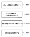
- the treatment includes a balloon positioning step S201, a mucous membrane extension step S202, a light irradiation portion positioning step S203, and a light irradiation step S204 shown in FIG.
- the mucous membrane extending step S202 includes a first expansion holding step.
- the first inflation holding step when the tactile sensor 41 provided on the outer surface of the balloon 22 detects that the tactile sensor 41 is in contact with the wall 2w, the operator operates the plunger (hereinafter, referred to as an injection part) 33. The infusion of saline into the balloon 22 is stopped to keep the balloon in an inflated state.
- balloon positioning step S201 the operator positions the balloon 22 fixed to one end of the shaft 21 of the balloon catheter 20 in the bladder 2 as shown in FIG.
- Reference numeral 14 in FIG. 3 is a positioning coloring portion.
- the colored portion 14 is a peripheral portion provided at a predetermined position of the shaft 21.
- the light irradiation portion 12 is arranged at a predetermined position in the through hole 24.
- the light irradiation portion 12 is arranged at a predetermined position in the inflated balloon 22 ( (See FIG. 5).
- the operator operates the injection part 33 of the injection device 30. Then, the physiological saline in the liquid storage space 32S is injected into the balloon 22 through the through hole 24 of the shaft 21 as the injection part 33 moves. Then, as shown in FIG. 4A, the physiological saline 3 fills the balloon 22, the through hole 24, and the probe insertion hole 26h.
- the balloon 22 starts to inflate by injecting the physiological saline 3.
- the operator has determined whether the remaining amount of the physiological saline 3 in the liquid storage space 32S has reached the vicinity of the second scale s2, or the second scale s2 and the third scale s3. Check if it is in between.
- a part of the outer surface of the balloon 22 comes into contact with the wall 2w of the bladder 2 as shown in FIG. 4B.
- the balloon 22 is expanded and the contact surface between the outer surface and the wall 2w is expanded.
- the tactile sensor 41 provided on the outer surface of the balloon 22 comes into contact with the mucous membrane of the wall 2w. Then, the tactile sensor 41 outputs a detection signal and the buzzer sounds. The operator checks the buzzer sound and at the same time stops the operation of the injection part 33, and checks whether or not the buzzer sound continues to be emitted. While the buzzer sounds, the outer surface of the balloon 22 contacts the substantially entire surface of the wall 2w, and the wall 2w is held in a stretched state.
- the operator advances the light irradiation portion 12 of the fiber probe 11 in the through hole 24 while checking the buzzer sound.
- 12 g and 12 s of the light irradiating part 12 are partially protruded from the balloon opening 24 a of the through hole 24 as shown in FIG. 5, and are arranged in the balloon 22 inflating the bladder 2.
- the fiber probe 11 is positioned and held by a holder (not shown).
- the operator emits light from the light irradiation unit 12 while checking the buzzer sound. That is, the operator operates, for example, a foot switch (not shown) for a predetermined time. Then, light is emitted from the light emitting device of the light source device, the light is transmitted through the fiber probe 11, emitted from the light emitting unit 12, passes through the balloon 22, and is applied to the mucous membrane of the wall 2w.
- the operator discharges the physiological saline 3 from the inside of the balloon 22 to deflate it, and removes the balloon catheter 20 out of the body.
- the bladder 2 can be expanded while gradually expanding the balloon 22. Then, when the tactile sensor 41 provided on the outer surface of the balloon 22 comes into contact with the mucous membrane of the wall 2w of the bladder 2, the injection of the physiological saline 3 into the balloon 22 is stopped, and the bladder 2 is inflated together with the balloon 22. Can be held at
- the wall 2w of the bladder 2 is expanded by the outer surface of the balloon 22 which is inflated and comes into contact.
- This extended state can be determined by confirming the buzzer sound that is generated when the tactile sensor 41 contacts the wall 2w of the bladder 2. Therefore, the operator can efficiently irradiate the mucous membrane of the wall 2w extended through the balloon 22 by emitting light from the light irradiation unit 12 of the fiber probe 11 in all directions while checking the buzzer sound.
- the syringe 32 is provided with scales s2 and s3 for notifying the lower and upper limits of the physiological saline 3 to be injected into the balloon 22.
- scales s2 and s3 for notifying the lower and upper limits of the physiological saline 3 to be injected into the balloon 22.
- the balloon positioning step S201 is executed again to solve the problem.
- the tactile sensor 41 is fixed to the outer surface of the balloon 22 at one location.
- the number of tactile sensors 41 is not limited to one and may be plural.
- tactile sensors 41a and 41b are provided on the outer surface of the balloon 22. In this configuration, the buzzer sounds when a detection signal is output from each tactile sensor 41. As a result, the contact between the outer surface of the balloon 22 and the wall 2w can be accurately determined.
- the position at which the tactile sensor 41 is provided depends on the shape of the balloon 22 inflated, the start position of the inflation, etc., and three or more tactile sensors 41 may be provided. Further, instead of ringing the buzzer, a lamp may be turned on, blinking, vibration of a vibrator, or the like to notify the operator that the wall 2w is extended by the balloon 22.
- the contact detection unit 40 is the tactile sensor 41 provided on the outer surface of the balloon 22.
- the contact detection unit 40 is not limited to the tactile sensor 41, and may be an imaging probe or the like including an image sensor.
- the balloon catheter system 1A includes an imaging probe 50 in addition to the light irradiation probe 10.
- the imaging probe 50 includes an imaging element 52 and a light emitting element (not shown) on the insertion portion distal end portion 51f, which is one end portion of the elongated insertion portion 51.
- the insertion portion base end portion 51r which is the opposite side of the insertion portion front end portion 51f, of the insertion portion 51 is connected to a camera control unit (not shown).
- the camera control unit generates an image pickup signal picked up by the image pickup element 52 into a video signal and outputs the video signal to a display device (not shown).
- the observation image captured by the image sensor 52 is displayed on the screen of the display device.
- An observation window and an illumination window which are not shown, are provided on the tip surface or the side surface of the insertion portion tip 51f.
- the medical staff places the insertion portion 51 in place of the fiber probe 11 in the through hole 24 of the shaft 21.
- the outer diameter of the insertion portion 51 is set to be the same as or slightly smaller than the outer diameter of the fiber probe 11.
- the mucosal extension step S202 includes a second expansion holding step instead of the first expansion holding step.
- the operator observes the image through the balloon 22 displayed on the screen of the display device to confirm that the balloon 22 is in contact with the wall 2w, and then the physiological saline solution is used. Injection into the balloon 22 is stopped. This holds the balloon 22 in an inflated state.
- the tumor treatment site is the bladder.
- the medical staff connects the syringe 32 and the liquid port portion 27 with the liquid feeding tube 31.
- a drug that reacts to the light emitted from the light irradiation unit 12 is intravenously injected into the patient.
- the holding portion on the opening 26m side of the probe port portion 26 has a function of holding the arrangement positions of the fiber probe 11 and the insertion portion 51, and the liquid supplied into the balloon 22 and the through hole 24 leaks to the outside. And a function of a sealing cock for preventing.
- the operator positions the balloon 22 fixed to one end of the shaft 21 of the balloon catheter 20 in the bladder 2 as shown in FIG. 6B.
- the operator injects the physiological saline 3 in the liquid storage space 32S in the mucous membrane extending step S202 as described above.
- the balloon 22 starts to expand after the physiological saline 3 is filled in the balloon 22, the through hole 24, and the probe insertion hole 26h.
- the operator continues the injection operation while performing the injection operation by the injection unit 33, observing the image displayed on the screen of the display device, confirming the remaining amount in the liquid storage space 32S, and the like. Then, as shown in FIG. 6C, a part of the outer surface of the balloon 22 (see reference numeral 22p in FIG. 6C) contacts the wall 2w of the bladder 2, and the wall 2w on the screen of the display device contacts the balloon 22. Mucous membrane is displayed.
- the operator observes the change in the contact area between the balloon 22 and the wall 2w while repeatedly performing the operation of injecting the physiological saline 3 and the operation of rotating the insertion portion 51 around the axis. Then, the operator confirms the image of the mucous membrane of the wall 2w which the outer surface of the balloon 22 is in close contact with the substantially entire surface of the wall 2w and extends over the balloon 22, and at the same time, the operation of the injection part 33 is stopped. As a result, the outer surface of the balloon 22 contacts the wall 2w and keeps the wall 2w extended.
- the process proceeds to the light irradiation unit positioning step S203.
- the operator removes the insertion part 51 from the through hole 24 of the shaft 21 and then inserts the fiber probe 11 of the light irradiation probe 10 into the through hole 24 to move the light irradiation part 12 to the position shown in FIG. It is placed in the balloon 22 that is inflated by contacting the wall 2w of the bladder 2, and the process proceeds to the light irradiation step S204 described above.
- the operator discharges the physiological saline 3 from the inside of the balloon 22 to deflate it, and removes the balloon catheter 20 out of the body.
- the imaging probe 50 is prepared in addition to the light irradiation probe 10.
- the surgeon confirms the image of the mucous membrane of the wall 2w extended through the balloon 22 captured on the screen by the image sensor 52 of the imaging probe 50, the injection of the physiological saline 3 into the balloon 22 is stopped. To do.
- the bladder 2 can be held in the expanded state in which light irradiation can be performed together with the balloon 22.
- the shaft 21 has a hole for insertion part (not shown) which is a first pipe through hole through which the insertion part 51 can be inserted and a hole for fiber probe (not shown) which is a second through hole for the fiber probe 11. (Shown), and a double lumen tube having.
- the insertion section 51 can be smoothly moved to the light irradiation section positioning step S203 and the light irradiation step S204 without removing the insertion section 51 from the insertion section hole, in the arranged state.
- the operator can re-check the image captured by the image sensor 52 of the imaging probe 50 in the light irradiation unit positioning step S203, and then move to the light irradiation step S204.
- the contact detection unit 40 is the imaging probe 50 including the imaging element 52.
- the contact detection unit may be the image pickup element 52A of the endoscope 60 having the treatment tool channel through which the shaft 21 of the balloon catheter 20 is inserted.
- the endoscope system shown in FIG. 7A has an endoscope 60, and the shaft 21 of the balloon catheter 20 is introduced into the treatment instrument channel from the treatment instrument opening 61 of the endoscope 60 and guided into, for example, the bladder.
- Reference numeral 62 is an endoscope insertion portion
- reference numeral 63 is an endoscope tip portion
- reference numeral 64 is an endoscope bending portion
- reference numeral 65 is an endoscope flexible tube portion.
- the endoscope bending portion 64 bends as the bending lever 67 provided on the endoscope operating portion 66 is operated.
- Reference numeral 68 is a universal code
- reference numeral 69 is a treatment instrument insertion port.
- the treatment instrument opening 61 and the treatment instrument insertion port 69 communicate with the treatment instrument channel.
- a signal line extending from the image pickup element 52A is built in the universal cord 68.
- the distal end surface of the endoscope distal end portion 63 of the endoscope insertion portion 62 is arranged near the bladder. Then, in the balloon positioning step S201, the operator positions the inside of the bladder 2 while observing the image of the balloon 22 fixed to the shaft 21 of the balloon catheter 20 inserted into the treatment instrument channel 71 as shown in FIG. 7B.
- the operator injects the physiological saline 3 in the liquid storage space 32S in the mucous membrane extending step S202 as described above.
- the balloon 22 starts to expand after the physiological saline 3 is filled in the balloon 22, the through hole 24, and the probe insertion hole 26h.
- the operator continues the injection operation while performing the injection operation by the injection unit 33, observing the image displayed on the screen of the display device, confirming the remaining amount in the liquid storage space 32S, and the like. Then, a part of the outer surface of the balloon 22 (see reference numeral 22p in FIGS. 7B and 7C) is brought into close contact with the observation window 72 of the endoscope 60, and the image of the balloon 22 or the balloon 22 is displayed on the screen of the display device. The mucous membrane of the wall 2w which is in contact with over 22 is displayed.
- the operator observes the change in the contact area between the balloon 22 and the wall 2w while repeatedly performing the operation of injecting the physiological saline 3 and the operation of the endoscope bending portion 64. Then, as shown in FIG. 7C, the operator confirms the image of the mucous membrane of the wall 2w which the outer surface of the balloon 22 adheres to substantially the entire surface of the wall 2w and extends through the balloon 22. To stop. As a result, the outer surface of the balloon 22 contacts the wall 2w and keeps the wall 2w extended.
- the process proceeds to the light irradiation unit positioning step S203.
- the operator places the light irradiation unit 12 in the balloon 22 that is in intimate contact with the wall 2w of the bladder 2 and inflated as shown in FIG.
- the process moves to S204.
- the endoscope insertion part 62 is pulled out of the body.
- the operator inserts the shaft 21 of the balloon catheter 20 of the balloon catheter system 1 into the treatment tool channel 71 of the endoscope 60 and positions it in the bladder. After that, the operator injects the physiological saline 3 to inflate the balloon 22 and passes over the balloon 22 with the image pickup element 52A of the endoscope 60, or directly contacts the outer surface of the balloon 22 with the wall 2w. Check.
- the injection of the physiological saline 3 into the balloon 22 is stopped.
- the bladder 2 can be held together with the balloon 22 in an expanded state in which light can be emitted.
Landscapes
- Health & Medical Sciences (AREA)
- Engineering & Computer Science (AREA)
- Biomedical Technology (AREA)
- Life Sciences & Earth Sciences (AREA)
- General Health & Medical Sciences (AREA)
- Veterinary Medicine (AREA)
- Public Health (AREA)
- Animal Behavior & Ethology (AREA)
- Heart & Thoracic Surgery (AREA)
- Pathology (AREA)
- Radiology & Medical Imaging (AREA)
- Nuclear Medicine, Radiotherapy & Molecular Imaging (AREA)
- Biophysics (AREA)
- Child & Adolescent Psychology (AREA)
- Pulmonology (AREA)
- Anesthesiology (AREA)
- Hematology (AREA)
- Vascular Medicine (AREA)
- Endoscopes (AREA)
- Media Introduction/Drainage Providing Device (AREA)
Abstract
L'invention concerne un système de cathéter à ballonnet comprenant : une sonde d'irradiation de lumière dotée d'une unité d'irradiation de lumière qui irradie de la lumière à l'extrémité distale d'une sonde à fibre ; un cathéter à ballonnet pourvu d'un arbre dans lequel la sonde d'irradiation de lumière peut être insérée et qui est muni d'un trou débouchant à travers lequel un liquide peut être pompé avec la sonde d'irradiation de lumière disposée à l'intérieur de celui-ci, et un ballonnet qui est fixé à une extrémité de l'arbre et qui peut être gonflé par un liquide injecté à travers le trou débouchant de l'arbre ; et un dispositif d'injection pourvu d'une unité de mesure qui peut mesurer la quantité de liquide injectée dans le ballonnet, et une unité d'injection qui, à travers le trou débouchant, injecte un liquide mesuré par l'unité de mesure dans le ballonnet, le liquide injecté dans le ballonnet gonfle le ballonnet pour dilater la paroi du site de traitement, et la paroi du site de traitement est maintenue dans un état expansé au moyen du ballonnet gonflé.
Applications Claiming Priority (2)
| Application Number | Priority Date | Filing Date | Title |
|---|---|---|---|
| US16/253,477 | 2019-01-22 | ||
| US16/253,477 US20200230378A1 (en) | 2019-01-22 | 2019-01-22 | Balloon catheter system and method for optical tumor treatment |
Publications (1)
| Publication Number | Publication Date |
|---|---|
| WO2020152928A1 true WO2020152928A1 (fr) | 2020-07-30 |
Family
ID=71609557
Family Applications (1)
| Application Number | Title | Priority Date | Filing Date |
|---|---|---|---|
| PCT/JP2019/041172 Ceased WO2020152928A1 (fr) | 2019-01-22 | 2019-10-18 | Système de cathéter à ballonnet et procédé pour photothérapie de tumeurs |
Country Status (2)
| Country | Link |
|---|---|
| US (1) | US20200230378A1 (fr) |
| WO (1) | WO2020152928A1 (fr) |
Cited By (3)
| Publication number | Priority date | Publication date | Assignee | Title |
|---|---|---|---|---|
| JPWO2021066012A1 (fr) * | 2019-09-30 | 2021-04-08 | ||
| JP2022126610A (ja) * | 2021-02-18 | 2022-08-30 | バイオセンス・ウエブスター・(イスラエル)・リミテッド | 光学測定を使用したバルーンカテーテルの組織の接触の検出 |
| WO2025205862A1 (fr) * | 2024-03-28 | 2025-10-02 | テルモ株式会社 | Cathéter à ballonnet |
Families Citing this family (1)
| Publication number | Priority date | Publication date | Assignee | Title |
|---|---|---|---|---|
| CN112402807B (zh) * | 2020-11-18 | 2021-11-23 | 中国人民解放军总医院 | 一种用于人体腔道及空腔器官内的光动力治疗器械 |
Citations (5)
| Publication number | Priority date | Publication date | Assignee | Title |
|---|---|---|---|---|
| JPH09502904A (ja) * | 1993-09-29 | 1997-03-25 | メディカル カレッジ オブ オハイオ | 前立腺細胞を治療するための光力学的療法の使用 |
| JP2012505041A (ja) * | 2008-10-07 | 2012-03-01 | エムシー10 インコーポレイテッド | 伸縮可能な集積回路およびセンサアレイを有するカテーテルバルーン |
| JP2016507267A (ja) * | 2012-12-21 | 2016-03-10 | ポール ホセイト, | バルーン内部から撮像するための撮像カテーテル |
| JP2018000241A (ja) * | 2016-06-27 | 2018-01-11 | 学校法人日本大学 | 医療用超音波システム及び医療用超音波装置 |
| JP2018538077A (ja) * | 2015-12-18 | 2018-12-27 | フォトキュア エイエスエイ | 光線力学的治療用装置 |
-
2019
- 2019-01-22 US US16/253,477 patent/US20200230378A1/en not_active Abandoned
- 2019-10-18 WO PCT/JP2019/041172 patent/WO2020152928A1/fr not_active Ceased
Patent Citations (5)
| Publication number | Priority date | Publication date | Assignee | Title |
|---|---|---|---|---|
| JPH09502904A (ja) * | 1993-09-29 | 1997-03-25 | メディカル カレッジ オブ オハイオ | 前立腺細胞を治療するための光力学的療法の使用 |
| JP2012505041A (ja) * | 2008-10-07 | 2012-03-01 | エムシー10 インコーポレイテッド | 伸縮可能な集積回路およびセンサアレイを有するカテーテルバルーン |
| JP2016507267A (ja) * | 2012-12-21 | 2016-03-10 | ポール ホセイト, | バルーン内部から撮像するための撮像カテーテル |
| JP2018538077A (ja) * | 2015-12-18 | 2018-12-27 | フォトキュア エイエスエイ | 光線力学的治療用装置 |
| JP2018000241A (ja) * | 2016-06-27 | 2018-01-11 | 学校法人日本大学 | 医療用超音波システム及び医療用超音波装置 |
Cited By (4)
| Publication number | Priority date | Publication date | Assignee | Title |
|---|---|---|---|---|
| JPWO2021066012A1 (fr) * | 2019-09-30 | 2021-04-08 | ||
| JP2022126610A (ja) * | 2021-02-18 | 2022-08-30 | バイオセンス・ウエブスター・(イスラエル)・リミテッド | 光学測定を使用したバルーンカテーテルの組織の接触の検出 |
| JP7814966B2 (ja) | 2021-02-18 | 2026-02-17 | バイオセンス・ウエブスター・(イスラエル)・リミテッド | 光学測定を使用したバルーンカテーテルの組織の接触の検出 |
| WO2025205862A1 (fr) * | 2024-03-28 | 2025-10-02 | テルモ株式会社 | Cathéter à ballonnet |
Also Published As
| Publication number | Publication date |
|---|---|
| US20200230378A1 (en) | 2020-07-23 |
Similar Documents
| Publication | Publication Date | Title |
|---|---|---|
| US10433821B2 (en) | Precision directed medical instruments | |
| US10864323B2 (en) | Modulated drug delivery | |
| WO2020152928A1 (fr) | Système de cathéter à ballonnet et procédé pour photothérapie de tumeurs | |
| US10463232B2 (en) | Anchored guidewire | |
| JP4810623B2 (ja) | 医療システム | |
| US11583694B2 (en) | Treatment method | |
| JP2019141635A (ja) | バルーン内視鏡ならびにその製造方法および使用方法 | |
| US20100121144A1 (en) | Endoscope Accessory | |
| JP2004508867A (ja) | 組織治療法および装置 | |
| JP6762035B2 (ja) | 治療物質運搬デバイス、及び治療物質運搬キット | |
| US20070219446A1 (en) | System and apparatus for imaging and treating hollow body cavities | |
| ES2763809T3 (es) | Lente en catéter de balón | |
| JP5330222B2 (ja) | 管腔通過確認装置、管腔通過確認方法、および管腔通過確認装置の製造方法 | |
| JP2000014663A (ja) | 前立腺肥大治療用装置 | |
| WO2017160270A1 (fr) | Administration modulée de médicament | |
| JP2025107237A (ja) | 照射デバイス | |
| KR101452683B1 (ko) | 풍선카테터 및 상기 풍선카테터를 구비한 카테터장치 | |
| CN218248144U (zh) | 用于胆道肿瘤光动力精准治疗的柱形光纤球囊导管装置 | |
| JP4847774B2 (ja) | 内視鏡 | |
| JP4920279B2 (ja) | 内視鏡 | |
| JP2004223032A (ja) | 圧迫止血装置 | |
| KR102840613B1 (ko) | 광 치료 장치 | |
| CN108938083B (zh) | 一种基于t型引流管通道的胆道造影激光治疗机 | |
| CN207561979U (zh) | 一种基于t型引流管通道的胆道造影激光治疗机 | |
| JPH11290324A (ja) | 超音波プローブ |
Legal Events
| Date | Code | Title | Description |
|---|---|---|---|
| 121 | Ep: the epo has been informed by wipo that ep was designated in this application |
Ref document number: 19911475 Country of ref document: EP Kind code of ref document: A1 |
|
| NENP | Non-entry into the national phase |
Ref country code: DE |
|
| 122 | Ep: pct application non-entry in european phase |
Ref document number: 19911475 Country of ref document: EP Kind code of ref document: A1 |
|
| NENP | Non-entry into the national phase |
Ref country code: JP |