WO2020158021A1 - Dispositif de commande de direction et procédé de commande de direction - Google Patents
Dispositif de commande de direction et procédé de commande de direction Download PDFInfo
- Publication number
- WO2020158021A1 WO2020158021A1 PCT/JP2019/032825 JP2019032825W WO2020158021A1 WO 2020158021 A1 WO2020158021 A1 WO 2020158021A1 JP 2019032825 W JP2019032825 W JP 2019032825W WO 2020158021 A1 WO2020158021 A1 WO 2020158021A1
- Authority
- WO
- WIPO (PCT)
- Prior art keywords
- vehicle
- steering
- control device
- wheel steering
- steering angle
- Prior art date
- Legal status (The legal status is an assumption and is not a legal conclusion. Google has not performed a legal analysis and makes no representation as to the accuracy of the status listed.)
- Ceased
Links
Images






Classifications
-
- B—PERFORMING OPERATIONS; TRANSPORTING
- B62—LAND VEHICLES FOR TRAVELLING OTHERWISE THAN ON RAILS
- B62D—MOTOR VEHICLES; TRAILERS
- B62D6/00—Arrangements for automatically controlling steering depending on driving conditions sensed and responded to, e.g. control circuits
- B62D6/002—Arrangements for automatically controlling steering depending on driving conditions sensed and responded to, e.g. control circuits computing target steering angles for front or rear wheels
-
- B—PERFORMING OPERATIONS; TRANSPORTING
- B62—LAND VEHICLES FOR TRAVELLING OTHERWISE THAN ON RAILS
- B62D—MOTOR VEHICLES; TRAILERS
- B62D15/00—Steering not otherwise provided for
- B62D15/02—Steering position indicators ; Steering position determination; Steering aids
- B62D15/027—Parking aids, e.g. instruction means
- B62D15/0285—Parking performed automatically
-
- B—PERFORMING OPERATIONS; TRANSPORTING
- B62—LAND VEHICLES FOR TRAVELLING OTHERWISE THAN ON RAILS
- B62D—MOTOR VEHICLES; TRAILERS
- B62D7/00—Steering linkage; Stub axles or their mountings
- B62D7/06—Steering linkage; Stub axles or their mountings for individually-pivoted wheels, e.g. on king-pins
- B62D7/14—Steering linkage; Stub axles or their mountings for individually-pivoted wheels, e.g. on king-pins the pivotal axes being situated in more than one plane transverse to the longitudinal centre line of the vehicle, e.g. all-wheel steering
- B62D7/15—Steering linkage; Stub axles or their mountings for individually-pivoted wheels, e.g. on king-pins the pivotal axes being situated in more than one plane transverse to the longitudinal centre line of the vehicle, e.g. all-wheel steering characterised by means varying the ratio between the steering angles of the steered wheels
- B62D7/1509—Steering linkage; Stub axles or their mountings for individually-pivoted wheels, e.g. on king-pins the pivotal axes being situated in more than one plane transverse to the longitudinal centre line of the vehicle, e.g. all-wheel steering characterised by means varying the ratio between the steering angles of the steered wheels with different steering modes, e.g. crab-steering, or steering specially adapted for reversing of the vehicle
Definitions
- the present invention relates to a steering control device for steering and controlling rear wheels in accordance with steering of front wheels of a vehicle.
- four-wheel steering type vehicles that can steer not only the front wheels but also the rear wheels are known.
- the ECU 40 of the steering control device 10 controls the steering angles of the left front wheel 21 to the right rear wheel 24 of the host vehicle 100.
- the ECU 40 indicates that the host vehicle 100 is parallel to the parking frame P. If not, the control is performed such that the steering directions of the left front wheel 21, the right front wheel 22, the left rear wheel 23, and the right rear wheel 24 are opposite directions, which are different directions. It becomes easier to change the direction, and it becomes easy to make the own vehicle 100 parallel to the parking frame P. Further, when the own vehicle 100 is parallel to the parking frame P, the ECU 40 sets the left front wheel 21 and the right front wheel 22.
- left rear wheel 23 and the right rear wheel 24 are controlled so that the steering directions are in the same direction and in phase with each other, so that the host vehicle 100 is moved in parallel while maintaining the direction of the host vehicle 100. It becomes easy to adjust the left and right gaps with the parking frame P.”
- Patent Document 1 unless the own vehicle is parallel to the parking frame, the steering control of the rear wheels with respect to the front wheels is not changed from the in-phase control to the in-phase control, so that the own vehicle is parallel to the parking frame. Until then, there was a problem that it was difficult to finely correct the posture of the vehicle. Further, when the steering direction of the rear wheels suddenly switches from the reverse phase of the front wheels to the same phase, the behavior of the vehicle during steering suddenly changes, which causes a problem that the driver feels uncomfortable.
- the present invention gradually adjusts the gain of the rear-wheel steering with respect to the front-wheel steering angle operated by the driver when the four-wheel steering vehicle is parked, according to the relative relationship between the own vehicle and the parking frame, and the vicinity of the parking frame.
- An object of the present invention is to provide a steering control device capable of reducing the steering load on the driver by enabling fine steering of the host vehicle.
- a vehicle steering control device of the present invention controls a rear wheel steering angle by a rear wheel steering system based on a front wheel steering angle by a driver's operation.
- the calculation device is provided to reduce the absolute value of the gain of the rear wheel steering angle with respect to the front wheel steering angle as the positional relationship between the vehicle and the parking frame becomes closer.
- the steering control device of the present invention when the four-wheel steering vehicle is parked, the gain of the rear wheel steering with respect to the front wheel steering angle operated by the driver is gradually adjusted according to the relative relationship between the own vehicle and the parking frame. Therefore, it is possible to finely steer the own vehicle in the vicinity of the parking frame, and it is possible to reduce the steering load on the driver.
- Example 1 Schematic configuration diagram of a vehicle of Example 1 1 is a schematic diagram of a rear wheel steering system according to a first embodiment.
- Functional block diagram of the steering control device of the first embodiment Operation flowchart of the parking determination unit of the steering control device according to the first embodiment
- the top view explaining the relationship between the vehicle of Example 1 and a parking frame.
- Conceptual diagram of gain adjustment of the first embodiment An example of time transition of the front wheel steering angle according to the first embodiment Specific Example of Relationship between ⁇ L x , ⁇ L y , ⁇ , and Gain when Parking Vehicle in Example 1
- Example 2 Schematic configuration diagram of a vehicle Functional block diagram of a steering control device according to a second embodiment The top view explaining the relationship between the vehicle of Example 2 and a parking frame.
- Functional block diagram of a steering control device according to a third embodiment Specific Example of Relationship between ⁇ f , ⁇ , v, and Gain when Parking Vehicle in Example 3 The top view explaining the relationship between the vehicle of Example 3 and a parking frame.
- the steering control device 1 according to the first embodiment of the present invention will be described with reference to FIGS. 1 to 8.
- FIG. 1 is a schematic configuration diagram of a vehicle 10 equipped with the steering control device 1 of the present embodiment.
- the vehicle 10 is a four-wheel steering (4WS) type vehicle that can steer both the front wheels 5 and the rear wheels 7.
- 4WS four-wheel steering
- the front wheels 5 and the rear wheels 7 are steered in the same direction.
- the front and rear wheels can be independently steered in opposite phases, and the minimum turning radius can be made smaller.
- the vehicle 10 includes a vehicle state sensor 2 for acquiring vehicle information such as vehicle speed information and shift lever information, a steering wheel 3 operated by a driver, a front wheel power steering device 4 for steering front wheels 5, and a rear wheel steering device 4.
- a rear wheel power steering device 6 that steers the wheels 7, an external world recognition sensor 8 that recognizes the external world of the vehicle 10 (a front recognition sensor 8f, a rear recognition sensor 8r), and a communication line (a part of which is illustrated) that connects them to each other. Is omitted).
- the steering control device 1 receives signals from the vehicle state sensor 2 and the external environment recognition sensor 8 via the communication line, and controls the front wheel power steering device 4 and the rear wheel power steering device 6 based on the received signals. Control.
- the steering control device 1 is actually a function of an ECU (Electronic Control Unit) including hardware such as a computing device such as a CPU, a main storage device, an auxiliary storage device, and a communication device. Then, while referring to the database recorded in the auxiliary storage device, the arithmetic unit executes the program loaded in the main storage device to realize each function of the parking determination unit 1a and the like described later. Description will be given while omitting such well-known techniques as appropriate.
- ECU Electronic Control Unit
- the front wheel power steering device 4 includes a steering sensor 3a (steering angle sensor, torque sensor, etc.) that detects a steering direction and a steering torque of the steering wheel 3 operated by a driver, and a front wheel rack shaft 4c connected to the front wheels 5 via a link. And a front wheel power steering motor 4b that applies a steering thrust to the front wheel rack shaft 4c, and a front wheel that applies a torque command to the front wheel power steering motor 4b based on a detection value of the steering sensor 3a (hereinafter referred to as "front wheel steering angle ⁇ f "). It comprises a steering angle control unit 4a.
- the front wheel power steering device 4 assists the steering of the front wheels 5 by causing the front wheel power steering motor 4b to generate steering thrust corresponding to the steering of the steering wheel 3 by the driver.
- the rear wheel power steering device 6 includes a rear wheel rack shaft 6c connected to the rear wheels 7 via a link, a rear wheel power steering motor 6b that applies steering thrust to the rear wheel rack shaft 6c, and a steering control device 1.
- the rear wheel steering angle control unit 6a provides a torque command to the rear wheel power steering motor 6b based on a command value (hereinafter, referred to as "rear wheel steering angle ⁇ r ").
- the rear wheel power steering device 6 causes the rear wheel power steering motor 6b to generate a steering thrust force corresponding to the command value from the steering control device 1, and steers the rear wheels 7.
- the relationship between the front wheel steering angle ⁇ f and the rear wheel steering angle ⁇ r will be described later.
- the external recognition sensor 8 processes image data captured by a stereo camera and recognizes obstacles and parking frames around the vehicle 10.
- the outside world recognition sensor 8 may be provided not only in the front and rear but also in the side of the vehicle for recognizing the side.
- the parking frame recognized by the outside world recognition sensor 8 is not limited to the area surrounded by the white line designated as the parking lot, and the vehicle 10 such as a vacant space between other vehicles or a vacant space surrounded by walls. It may be a parking area.
- a rear wheel steering angle control unit 6a and a rear wheel power steering motor 6b are mainly arranged between the steering control device 1 and the rear wheels 7.
- the vehicle information vehicle speed information, shift lever information
- the outside world recognition sensor 8 or the outside of the vehicle for example, a parking facility management system.
- Each information of the parking frame information of is input.
- the steering control device 1 calculates a predetermined rear wheel steering angle ⁇ r based on these input information, and gives the obtained rear wheel steering angle ⁇ r to the rear wheel steering angle control unit 6a.
- the rear wheel steering angle control unit 6a generates a torque command according to the difference between the input rear wheel steering angle ⁇ r and the actual rear wheel steering angle, and outputs the torque command to the rear wheel power steering motor 6b.
- the steering thrust is generated to change the direction of the rear wheels 7 to control the traveling direction of the vehicle 10.
- FIG. 3 is a functional block diagram showing details of the steering control device 1.
- the steering control device 1 includes a parking determination unit 1a, a vehicle/parking frame relationship determination unit 1b, and a gain control unit 1c.
- the parking determination unit 1a determines whether the driving mode of the vehicle 10 is the parking driving mode.
- the own vehicle/parking frame relationship determination unit 1b calculates the relationship between the vehicle 10 and the parking frame 9, and the gain control unit 1c is calculated by the own vehicle/parking frame relationship determination unit 1b.
- the rear wheel steering angle ⁇ r is determined based on the obtained information.
- ⁇ Parking determination unit 1a> As a method of determining the driving mode of the vehicle 10 by the parking determination unit 1a, there are a method of determining with a driver trigger and a method of determining based on vehicle information.
- the driver trigger method is a method of determining that the driving mode has been switched to the parking driving mode when the driver indicates to the vehicle 10 to start parking, such as when the driver presses the parking start button.
- the vehicle information method is a method of determining that the driving mode is switched to the parking driving mode based on the vehicle information (vehicle speed information, shift lever information) input from the vehicle state sensor 2. An example of this is shown in the flowchart of FIG.
- the parking determination unit 1a acquires vehicle information (vehicle speed information, shift lever information) necessary for determining the driving mode from the vehicle state sensor 2.
- the parking determination unit 1a determines whether the vehicle 10 is traveling at an extremely low speed (for example, 5 km/h or less) based on the acquired vehicle speed information.
- the processing is terminated after determining the normal operation mode, and when the vehicle is traveling at an extremely low speed, the processing proceeds to step S3.
- step S3 the parking determination unit 1a confirms the position of the shift lever based on the acquired shift lever information.
- a parking pattern such as parallel parking or reverse parking
- the vehicle 10 often repeats forward and reverse, and the shift lever enters "R" (Reverse, reverse) at least once. Based on such characteristics, the time shift of the shift lever position is observed, and when the shift lever does not enter "R" for a certain period of time, it is determined that the operation mode is the normal operation mode, and the processing is ended. On the other hand, if the shift lever enters "R" even once within a fixed time, it is determined that the operation mode is the parking operation mode, and the process ends.
- the flowchart in FIG. 4 is an example of a method of determining the driving mode using vehicle information, and determination may be performed using vehicle information other than vehicle speed information and shift lever information.
- vehicle information other than vehicle speed information and shift lever information.
- the time change of the front wheel steering angle, the accelerator pedal, the brake pedal, etc. may be used together when determining the driving mode.
- the driving mode may be estimated based on the surrounding situation detected by the outside world recognition sensor 8 or the map data (the vehicle 10 is in the parking area, etc.).
- ⁇ Own vehicle/parking frame relation determination unit 1b> Next, the relationship between the vehicle 10 and the parking frame 9 calculated by the own vehicle/parking frame relationship determination unit 1b will be described with reference to FIG. FIG.
- the lateral direction (lateral direction) of the parking frame 9 is x direction
- the longitudinal direction (front and rear direction) is y.
- the direction is.
- the own vehicle/parking frame relationship determination unit 1b grasps the position and shape of the parking frame 9 based on the parking frame information received from the outside world recognition sensor 8 or the outside of the vehicle.
- the parking frame 9 grasped by the own vehicle/parking frame relationship determination unit 1b is defined by its center coordinates 9C , an ideal posture angle ⁇ i during parking, an x-direction distance 9 x , and a y-direction distance 9 y .
- the relationship between the vehicle 10 and the parking frame 9 is the attitude angle difference ⁇ between the attitude angle ⁇ of the vehicle 10 and the ideal attitude angle ⁇ i , the x-direction distance ⁇ L x of the center coordinates 9 C of the vehicle 10 and the parking frame 9, and the vehicle 10 and the parking frame. It is expressed by the y-direction distance ⁇ L y of the center coordinate 9 C of the frame 9.
- the reference point of the vehicle 10 is the vehicle center point. Further, in FIG.
- the x-direction distance ⁇ L x and the y-direction distance ⁇ L y are represented by the relationship between the vehicle 10 and the center coordinates 9 C of the parking frame, but as a relationship with the points forming the parking frame 9. May be represented.
- ⁇ Gain controller 1c> After the relationship between the vehicle 10 and the parking frame 9 is calculated by the own vehicle/parking frame relationship determination unit 1b, the gain control unit 1c adjusts the gain of the rear wheel steering angle ⁇ r with respect to the front wheel steering angle ⁇ f . A gain adjusting method by the gain control unit 1c will be described with reference to FIGS.
- the gain control unit 1c positions the vehicle 10 in the rectangular area A 0 illustrated in FIG. 5, for example. If it is, the following gain adjustment control is started.
- the gain control unit 1c controls the gain of the rear wheel steering ⁇ r with respect to the front wheel steering angle ⁇ f to be constant.
- the minimum turning radius of the vehicle can be reduced, and the yaw motion is facilitated.
- the attitude angle of the vehicle changes significantly, and the attitude angle difference ⁇ greatly decreases.
- the attitude angle difference ⁇ is equal to or less than the threshold value (that is, when the attitude angle ⁇ of the vehicle 10 approaches the ideal attitude angle ⁇ i )
- the rear wheel steering with respect to the front wheel steering angle ⁇ f is changed according to the magnitude of the attitude angle difference ⁇ .
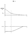
- Vary the gain of the angle ⁇ r Specifically, as shown in FIG. 6, the absolute value of the gain approaches 0 as the attitude angle difference ⁇ becomes smaller.
- the rear wheel steering angle ⁇ r is smaller than in the conventional control in which the gain is constant regardless of the attitude angle difference ⁇ , and the yaw motion of the vehicle 10 is less likely to occur.
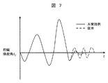
- the driver can easily change the attitude angle ⁇ of the vehicle 10 by a small amount, and as shown in FIG. 7, the correction steering angle of the driver near the parking frame is reduced and the steering frequency becomes a low frequency. The steering load on the driver can be reduced.
- the gain of the rear wheel steering angle ⁇ r with respect to the front wheel steering angle ⁇ f is adjusted according to the magnitude of the attitude angle difference ⁇ , but the x direction distance ⁇ L x and the y direction distance ⁇ L y are also taken into consideration.
- the gain may be adjusted by adjusting the gain. However, in this case, if the gain is set by giving priority to the attitude angle difference ⁇ over the x-direction distance ⁇ L x and the y-direction distance ⁇ L y , it is possible to realize steering more in line with the driver's feeling.
- FIG. 8 exemplifies a time transition of the x-direction distance ⁇ L x , the y-direction distance ⁇ L y , the attitude angle difference ⁇ , and the gain when the vehicle 10 is parked in the parking frame 9 shown in FIG.
- the driver operates the steering wheel 3 so as to gradually decrease the attitude angle difference ⁇ while reducing the x-direction distance ⁇ L x .
- the attitude angle ⁇ of the vehicle 10 is changed significantly while gradually reducing the x-direction distance ⁇ L x and the y-direction distance ⁇ L y .
- the attitude angle difference ⁇ is sharply reduced.
- the gain is constant and the value is the same as before.
- the driver makes the y-direction distance ⁇ L y closer to 0 while finely correcting the attitude angle difference ⁇ .
- the gain control unit 1c makes the gain of the rear-wheel steering angle ⁇ r relative to the front-wheel steering angle ⁇ f close to 0, which allows a slight change in the posture angle, thereby reducing the steering load on the driver's parking.
- the gain of the rear-wheel steering angle ⁇ r with respect to the front-wheel steering angle ⁇ f operated by the driver is controlled by the vehicle and the parking. Since the vehicle is gradually adjusted in accordance with the relative relationship between the frames, it is possible to finely steer the vehicle in the vicinity of the parking frame and reduce the steering load on the driver.
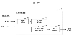
- the vehicle 10 according to the first embodiment includes the outside world recognition sensor 8 for recognizing the parking frame 9, but the vehicle 11 according to the present embodiment does not include the outside world recognition sensor 8 as illustrated in FIG. 9. Therefore, as shown in FIG. 10, unlike the first embodiment, the parking frame information is not input to the steering control device 1 of the present embodiment, but like the first embodiment, the front wheel steering angle information, the vehicle speed information, Each piece of shift lever information is input.
- the parking frame estimation unit 1d is added so that the same effect as that of the first embodiment can be obtained without inputting the parking frame information, and the parking frame estimated here is added.
- the rear wheel steering angle ⁇ r is decided based on the relative relationship between the vehicle and the vehicle.
- the operations of the parking determination unit 1a, the own vehicle/parking frame relation determination unit 1b, and the gain control unit 1c are the same as those in the first embodiment, and therefore, the description overlapping with the first embodiment will be omitted below.
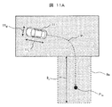
- the parking frame estimation unit 1d first predicts the vehicle 11 based on the front wheel steering angle ⁇ f , the steering angular velocity ⁇ , and the vehicle speed v, as illustrated in FIG. 11A. Estimate the path P 1 .
- the steering angular velocity ⁇ is a time derivative of the front wheel steering angle ⁇ f .
- the parking space estimation unit 1d is based on the predicted path P 1 that is estimated, estimates the parking space 9a.
- the estimated route end point P 1e is set as the center point of the parking frame 9a, and the total length 11 L and the total width 11 W of the vehicle 11 plus a margin is set as a distance from the parking frame center point (estimated route end point P 1e ).
- the parking frame 9a can be estimated by adding and subtracting. If it is difficult to estimate the y-direction distance 9 y of the parking frame 9 a from the vehicle speed v, the estimation need not be performed.
- the estimation accuracy by the parking frame estimation unit 1d improves, so that the margin amount added to the total length 11 L or the total width 11 W of the vehicle 11 is small. It may be a value.
- the parking frame 9b estimated at the end of parking becomes smaller than the parking frame 9a estimated at the start of parking, and it is considered that the parking frame 9b is closer to the actual parking frame 9.
- the gain of the rear-wheel steering angle ⁇ r with respect to the front-wheel steering angle ⁇ f operated by the driver is as follows even in the vehicle without the external environment recognition sensor 8. Since the vehicle is gradually adjusted according to the relative relationship between the own vehicle and the parking frame, it is possible to finely steer the own vehicle in the vicinity of the parking frame and reduce the steering load on the driver.
- the own vehicle/parking frame relation determination unit 1b performs calculation based on the parking frame or the like recognized by the external recognition sensor 8, and in the second embodiment, based on the parking frame estimated by the parking frame estimation unit 1d, although an appropriate gain value was set in the gain control unit 1c based on the calculation result, in the present embodiment, the gain control is performed without using the parking frame information from the external world recognition sensor 8 or the parking frame estimation unit 1d.
- the unit 1c sets an appropriate gain.
- the parking determination unit 1a detects the shift to the parking operation mode, the gain control portion 1c, the vehicle speed v, the front wheel steering angle [delta] f, on the basis of the time change data of the steering angular velocity omega, for front-wheel steering angle [delta] f
- the gain of the rear wheel steering angle ⁇ r is adjusted. This detailed procedure will be described with reference to FIGS. 13 and 14.
- Fig. 13 shows an example of the parking pattern of the driver.
- the posture of the vehicle 11 changes at the same time as the vehicle speed v is increased after the vehicle is stopped. Then, the operation of the handle 3 is started.
- An example of the driver performing this operation is in the area A 1 in FIG. 14 away from the area where the driver is trying to park.
- the driver steers the steering wheel 3 largely and starts decelerating in order to secure the yaw motion of the vehicle 11.
- the steering angular velocity ⁇ has a positive value.
- An example of the driver performing this operation is in the area A 2 in FIG.
- the steering wheel 3 is turned back while maintaining the vehicle speed v so that the posture angle ⁇ of the vehicle 11 converges to the ideal posture angle ⁇ i. Is done.
- An example of the driver performing this steering is in the area A 3 of FIG. In this region, when it is determined that the vehicle attitude angle is not significantly changed by comparing the vehicle speed v, the front wheel steering angle ⁇ f , the steering angular velocity ⁇ with time, and the positive/negative of the steering angle and the steering angular velocity ⁇ , Gradually reduce the gain of the rear wheels from the initial value.
- the driver approaches the vehicle speed v to 0 while performing a slight steering in order to finely correct the attitude angle ⁇ of the vehicle 11.
- This minute steering does not always have to be performed in one direction, and may be continuously performed in both directions as shown in FIG.
- An example of the driver performing this steering is in the area A 4 in FIG.
- the absolute value of the gain of the rear wheel steering angle ⁇ r with respect to the front wheel steering angle ⁇ f is brought close to 0 from the time transition of the vehicle speed v, the front wheel steering angle, and the steering angular velocity ⁇ .
- the control is similar to that of two-wheel steering, and the attitude angle of the vehicle is less likely to change, and the steering load on the driver is reduced.
- the gain of the rear wheel steering angle ⁇ r with respect to the front wheel steering angle ⁇ f operated by the driver is Since the vehicle is gradually adjusted according to the behavior of the vehicle, it is possible to finely steer the own vehicle and reduce the steering load on the driver.
- the present invention is not limited to the above-mentioned embodiments, but includes various modifications.
- the above-described embodiments have been described in detail for the purpose of explaining the present invention in an easy-to-understand manner, and are not necessarily limited to having all the configurations.
- SYMBOLS 1... Steering control device, 1a... Parking determination part, 1b... Own vehicle/parking frame relation determination part, 1c... Gain control part, 1d... Parking frame estimation part, 2... Vehicle state sensor, 3... Steering wheel, 3a... Steering sensor 4... Front wheel power steering device, 4a... Front wheel steering angle control unit 4b... Front wheel power steering motor, 4c... Front wheel rack shaft, 5... Front wheel, 6... Rear wheel power steering device, 6a... Rear wheel steering angle control unit, 6b ... rear wheel power steering motor, 6c... rear wheel rack shaft, 7... rear wheel, 8... external recognition sensor, 8f... front recognition sensor, 8r... rear recognition sensor, 9, 9a, 9b, 9c... parking frame 10, 11... Vehicle
Landscapes
- Engineering & Computer Science (AREA)
- Chemical & Material Sciences (AREA)
- Combustion & Propulsion (AREA)
- Transportation (AREA)
- Mechanical Engineering (AREA)
- Physics & Mathematics (AREA)
- Mathematical Physics (AREA)
- Steering Control In Accordance With Driving Conditions (AREA)
- Steering-Linkage Mechanisms And Four-Wheel Steering (AREA)
- Control Of Driving Devices And Active Controlling Of Vehicle (AREA)
Abstract
Le but de la présente invention est de fournir un dispositif de commande de direction qui peut réduire une charge de direction sur un conducteur pendant le stationnement d'un véhicule à quatre roues directrices, en permettant une orientation fine du véhicule à proximité d'une place de stationnement par réglage progressif, en fonction d'une corrélation entre le véhicule et la place de stationnement, d'un gain de direction de roue arrière δr par rapport à un angle de direction de roue avant δf commandé par le conducteur. Afin de satisfaire ce but, le dispositif de commande de direction de véhicule de la présente invention commande un angle de direction de roue arrière d'un système de direction de roue arrière sur la base d'un angle de direction de roue avant commandé par un conducteur, et comprend un dispositif de calcul qui, lorsque le véhicule passe à un mode de conduite de stationnement, réduit la valeur absolue d'un gain de l'angle de direction de roue arrière par rapport à l'angle de direction de roue avant lorsque le véhicule s'approche de la place de stationnement.
Priority Applications (3)
| Application Number | Priority Date | Filing Date | Title |
|---|---|---|---|
| DE112019006007.4T DE112019006007B4 (de) | 2019-01-28 | 2019-08-22 | Lenksteuervorrichtung und -verfahren |
| CN201980085432.8A CN113260553B (zh) | 2019-01-28 | 2019-08-22 | 转向控制装置和转向控制方法 |
| US17/416,126 US11975775B2 (en) | 2019-01-28 | 2019-08-22 | Steering control device and steering control method |
Applications Claiming Priority (2)
| Application Number | Priority Date | Filing Date | Title |
|---|---|---|---|
| JP2019-012085 | 2019-01-28 | ||
| JP2019012085A JP7203617B2 (ja) | 2019-01-28 | 2019-01-28 | 操舵制御装置、および、操舵制御方法 |
Publications (1)
| Publication Number | Publication Date |
|---|---|
| WO2020158021A1 true WO2020158021A1 (fr) | 2020-08-06 |
Family
ID=71840530
Family Applications (1)
| Application Number | Title | Priority Date | Filing Date |
|---|---|---|---|
| PCT/JP2019/032825 Ceased WO2020158021A1 (fr) | 2019-01-28 | 2019-08-22 | Dispositif de commande de direction et procédé de commande de direction |
Country Status (5)
| Country | Link |
|---|---|
| US (1) | US11975775B2 (fr) |
| JP (1) | JP7203617B2 (fr) |
| CN (1) | CN113260553B (fr) |
| DE (1) | DE112019006007B4 (fr) |
| WO (1) | WO2020158021A1 (fr) |
Families Citing this family (6)
| Publication number | Priority date | Publication date | Assignee | Title |
|---|---|---|---|---|
| KR20230001331A (ko) * | 2021-06-28 | 2023-01-04 | 현대자동차주식회사 | 자동차용 후륜 조향 제어 시스템 및 방법 |
| KR20230028973A (ko) * | 2021-08-23 | 2023-03-03 | 현대모비스 주식회사 | 4륜 조향 제어 장치 및 방법 |
| CN114312998B (zh) * | 2022-01-14 | 2023-03-28 | 中国第一汽车股份有限公司 | 后轮转向控制方法、装置、控制单元、车辆及存储介质 |
| KR102662632B1 (ko) * | 2022-01-14 | 2024-05-03 | 현대모비스 주식회사 | 4륜 독립 조향 장치 및 그 제어 방법 |
| US12296905B2 (en) | 2022-10-27 | 2025-05-13 | Trimble Inc. | Techniques for controlling autonomous 4WS vehicles |
| CN120462376A (zh) * | 2024-07-16 | 2025-08-12 | 比亚迪股份有限公司 | 泊车控制方法、设备、存储介质以及一种车辆 |
Citations (4)
| Publication number | Priority date | Publication date | Assignee | Title |
|---|---|---|---|---|
| JPS61163063A (ja) * | 1985-01-11 | 1986-07-23 | Fuji Heavy Ind Ltd | 自動車の前後輪操舵装置 |
| JPH0891238A (ja) * | 1994-09-28 | 1996-04-09 | Fuji Heavy Ind Ltd | 後輪操舵装置の制御方法 |
| JPH08287398A (ja) * | 1995-04-18 | 1996-11-01 | Toyota Motor Corp | 車両誘導装置 |
| JP2011225019A (ja) * | 2010-04-15 | 2011-11-10 | Toyota Motor Corp | 操舵制御装置 |
Family Cites Families (8)
| Publication number | Priority date | Publication date | Assignee | Title |
|---|---|---|---|---|
| JP3899739B2 (ja) * | 1999-09-21 | 2007-03-28 | 日産自動車株式会社 | 車両用操舵装置 |
| US8430192B2 (en) | 2010-01-04 | 2013-04-30 | Carla R. Gillett | Robotic omniwheel vehicle |
| US9586471B2 (en) | 2013-04-26 | 2017-03-07 | Carla R. Gillett | Robotic omniwheel |
| WO2018021325A1 (fr) * | 2016-07-28 | 2018-02-01 | 日本精工株式会社 | Dispositif de direction assistée électrique |
| MX377381B (es) * | 2017-06-23 | 2025-03-10 | Nissan Motor | Método de control de estacionamiento y dispositivo de control de estacionamiento. |
| US10960820B2 (en) * | 2017-08-03 | 2021-03-30 | Mitsubishi Electric Corporation | Vehicle periphery image display device and vehicle periphery image display method |
| KR20230028973A (ko) * | 2021-08-23 | 2023-03-03 | 현대모비스 주식회사 | 4륜 조향 제어 장치 및 방법 |
| KR102662632B1 (ko) * | 2022-01-14 | 2024-05-03 | 현대모비스 주식회사 | 4륜 독립 조향 장치 및 그 제어 방법 |
-
2019
- 2019-01-28 JP JP2019012085A patent/JP7203617B2/ja active Active
- 2019-08-22 WO PCT/JP2019/032825 patent/WO2020158021A1/fr not_active Ceased
- 2019-08-22 DE DE112019006007.4T patent/DE112019006007B4/de active Active
- 2019-08-22 CN CN201980085432.8A patent/CN113260553B/zh active Active
- 2019-08-22 US US17/416,126 patent/US11975775B2/en active Active
Patent Citations (4)
| Publication number | Priority date | Publication date | Assignee | Title |
|---|---|---|---|---|
| JPS61163063A (ja) * | 1985-01-11 | 1986-07-23 | Fuji Heavy Ind Ltd | 自動車の前後輪操舵装置 |
| JPH0891238A (ja) * | 1994-09-28 | 1996-04-09 | Fuji Heavy Ind Ltd | 後輪操舵装置の制御方法 |
| JPH08287398A (ja) * | 1995-04-18 | 1996-11-01 | Toyota Motor Corp | 車両誘導装置 |
| JP2011225019A (ja) * | 2010-04-15 | 2011-11-10 | Toyota Motor Corp | 操舵制御装置 |
Also Published As
| Publication number | Publication date |
|---|---|
| US11975775B2 (en) | 2024-05-07 |
| DE112019006007T5 (de) | 2021-09-02 |
| DE112019006007B4 (de) | 2024-11-07 |
| CN113260553A (zh) | 2021-08-13 |
| JP7203617B2 (ja) | 2023-01-13 |
| JP2020117180A (ja) | 2020-08-06 |
| CN113260553B (zh) | 2023-08-04 |
| US20220073133A1 (en) | 2022-03-10 |
Similar Documents
| Publication | Publication Date | Title |
|---|---|---|
| JP7203617B2 (ja) | 操舵制御装置、および、操舵制御方法 | |
| CN115140157B (zh) | 用于车辆的转向控制方法、装置、存储介质及车辆 | |
| JP7663315B2 (ja) | 車両の操舵支援装置 | |
| JP5299756B2 (ja) | 車両 | |
| JP3896995B2 (ja) | 車両用走行支援装置 | |
| WO2020166092A1 (fr) | Dispositif de commande de véhicule et procédé de commande de véhicule | |
| WO2019159562A1 (fr) | Dispositif d'aide à la conduite, procédé d'aide à la conduite, et système d'aide à la conduite | |
| JP5347499B2 (ja) | 車両制御装置及び車両制御方法 | |
| JP6374308B2 (ja) | 車両の制御装置及び車両の制御方法 | |
| JP6377971B2 (ja) | 車両の挙動制御装置及び車両の挙動制御方法 | |
| CN118529138A (zh) | 四轮转向车辆的控制装置 | |
| JP3896994B2 (ja) | 車両用走行支援装置 | |
| CN118494597A (zh) | 适用多驾驶场景的上下转中位同步方法及系统 | |
| JP5962074B2 (ja) | 車両用舵角制御装置 | |
| JP2006069496A (ja) | 前後輪操舵制御装置 | |
| JP4752306B2 (ja) | 車両用操舵装置 | |
| JP2005324655A (ja) | 車両用後輪操舵装置 | |
| JP3736370B2 (ja) | 車両用操舵装置 | |
| JPH11245838A (ja) | 車両用後輪操舵制御装置 | |
| JP7724793B2 (ja) | 経路生成装置および走行支援制御装置 | |
| JP2006069498A (ja) | 前後輪操舵制御装置 | |
| JP2005324744A (ja) | 車両用自動操舵装置 | |
| JP2023074883A (ja) | 車両制御方法 | |
| JP2007038696A (ja) | 操舵支援装置 | |
| KR20190115676A (ko) | 주차 충돌 방지를 위한 후륜 조향 보정 장치 및 방법 |
Legal Events
| Date | Code | Title | Description |
|---|---|---|---|
| 121 | Ep: the epo has been informed by wipo that ep was designated in this application |
Ref document number: 19912649 Country of ref document: EP Kind code of ref document: A1 |
|
| 122 | Ep: pct application non-entry in european phase |
Ref document number: 19912649 Country of ref document: EP Kind code of ref document: A1 |