WO2020158065A1 - 高強度鋼板およびその製造方法 - Google Patents
高強度鋼板およびその製造方法 Download PDFInfo
- Publication number
- WO2020158065A1 WO2020158065A1 PCT/JP2019/041131 JP2019041131W WO2020158065A1 WO 2020158065 A1 WO2020158065 A1 WO 2020158065A1 JP 2019041131 W JP2019041131 W JP 2019041131W WO 2020158065 A1 WO2020158065 A1 WO 2020158065A1
- Authority
- WO
- WIPO (PCT)
- Prior art keywords
- steel sheet
- less
- area ratio
- strength steel
- hot
- Prior art date
- Legal status (The legal status is an assumption and is not a legal conclusion. Google has not performed a legal analysis and makes no representation as to the accuracy of the status listed.)
- Ceased
Links
Classifications
-
- C—CHEMISTRY; METALLURGY
- C21—METALLURGY OF IRON
- C21D—MODIFYING THE PHYSICAL STRUCTURE OF FERROUS METALS; GENERAL DEVICES FOR HEAT TREATMENT OF FERROUS OR NON-FERROUS METALS OR ALLOYS; MAKING METAL MALLEABLE, e.g. BY DECARBURISATION OR TEMPERING
- C21D9/00—Heat treatment, e.g. annealing, hardening, quenching or tempering, adapted for particular articles; Furnaces therefor
- C21D9/46—Heat treatment, e.g. annealing, hardening, quenching or tempering, adapted for particular articles; Furnaces therefor for sheet metals
-
- B—PERFORMING OPERATIONS; TRANSPORTING
- B32—LAYERED PRODUCTS
- B32B—LAYERED PRODUCTS, i.e. PRODUCTS BUILT-UP OF STRATA OF FLAT OR NON-FLAT, e.g. CELLULAR OR HONEYCOMB, FORM
- B32B15/00—Layered products comprising a layer of metal
- B32B15/01—Layered products comprising a layer of metal all layers being exclusively metallic
- B32B15/013—Layered products comprising a layer of metal all layers being exclusively metallic one layer being formed of an iron alloy or steel, another layer being formed of a metal other than iron or aluminium
-
- C—CHEMISTRY; METALLURGY
- C21—METALLURGY OF IRON
- C21D—MODIFYING THE PHYSICAL STRUCTURE OF FERROUS METALS; GENERAL DEVICES FOR HEAT TREATMENT OF FERROUS OR NON-FERROUS METALS OR ALLOYS; MAKING METAL MALLEABLE, e.g. BY DECARBURISATION OR TEMPERING
- C21D1/00—General methods or devices for heat treatment, e.g. annealing, hardening, quenching or tempering
- C21D1/18—Hardening; Quenching with or without subsequent tempering
- C21D1/185—Hardening; Quenching with or without subsequent tempering from an intercritical temperature
-
- C—CHEMISTRY; METALLURGY
- C21—METALLURGY OF IRON
- C21D—MODIFYING THE PHYSICAL STRUCTURE OF FERROUS METALS; GENERAL DEVICES FOR HEAT TREATMENT OF FERROUS OR NON-FERROUS METALS OR ALLOYS; MAKING METAL MALLEABLE, e.g. BY DECARBURISATION OR TEMPERING
- C21D1/00—General methods or devices for heat treatment, e.g. annealing, hardening, quenching or tempering
- C21D1/18—Hardening; Quenching with or without subsequent tempering
- C21D1/19—Hardening; Quenching with or without subsequent tempering by interrupted quenching
-
- C—CHEMISTRY; METALLURGY
- C21—METALLURGY OF IRON
- C21D—MODIFYING THE PHYSICAL STRUCTURE OF FERROUS METALS; GENERAL DEVICES FOR HEAT TREATMENT OF FERROUS OR NON-FERROUS METALS OR ALLOYS; MAKING METAL MALLEABLE, e.g. BY DECARBURISATION OR TEMPERING
- C21D1/00—General methods or devices for heat treatment, e.g. annealing, hardening, quenching or tempering
- C21D1/18—Hardening; Quenching with or without subsequent tempering
- C21D1/25—Hardening, combined with annealing between 300 degrees Celsius and 600 degrees Celsius, i.e. heat refining ("Vergüten")
-
- C—CHEMISTRY; METALLURGY
- C21—METALLURGY OF IRON
- C21D—MODIFYING THE PHYSICAL STRUCTURE OF FERROUS METALS; GENERAL DEVICES FOR HEAT TREATMENT OF FERROUS OR NON-FERROUS METALS OR ALLOYS; MAKING METAL MALLEABLE, e.g. BY DECARBURISATION OR TEMPERING
- C21D8/00—Modifying the physical properties of ferrous metals or ferrous alloys by deformation combined with, or followed by, heat treatment
- C21D8/02—Modifying the physical properties of ferrous metals or ferrous alloys by deformation combined with, or followed by, heat treatment during manufacturing of plates or strips
- C21D8/0221—Modifying the physical properties of ferrous metals or ferrous alloys by deformation combined with, or followed by, heat treatment during manufacturing of plates or strips characterised by the working steps
- C21D8/0226—Hot rolling
-
- C—CHEMISTRY; METALLURGY
- C21—METALLURGY OF IRON
- C21D—MODIFYING THE PHYSICAL STRUCTURE OF FERROUS METALS; GENERAL DEVICES FOR HEAT TREATMENT OF FERROUS OR NON-FERROUS METALS OR ALLOYS; MAKING METAL MALLEABLE, e.g. BY DECARBURISATION OR TEMPERING
- C21D8/00—Modifying the physical properties of ferrous metals or ferrous alloys by deformation combined with, or followed by, heat treatment
- C21D8/02—Modifying the physical properties of ferrous metals or ferrous alloys by deformation combined with, or followed by, heat treatment during manufacturing of plates or strips
- C21D8/0221—Modifying the physical properties of ferrous metals or ferrous alloys by deformation combined with, or followed by, heat treatment during manufacturing of plates or strips characterised by the working steps
- C21D8/0236—Cold rolling
-
- C—CHEMISTRY; METALLURGY
- C21—METALLURGY OF IRON
- C21D—MODIFYING THE PHYSICAL STRUCTURE OF FERROUS METALS; GENERAL DEVICES FOR HEAT TREATMENT OF FERROUS OR NON-FERROUS METALS OR ALLOYS; MAKING METAL MALLEABLE, e.g. BY DECARBURISATION OR TEMPERING
- C21D8/00—Modifying the physical properties of ferrous metals or ferrous alloys by deformation combined with, or followed by, heat treatment
- C21D8/02—Modifying the physical properties of ferrous metals or ferrous alloys by deformation combined with, or followed by, heat treatment during manufacturing of plates or strips
- C21D8/0247—Modifying the physical properties of ferrous metals or ferrous alloys by deformation combined with, or followed by, heat treatment during manufacturing of plates or strips characterised by the heat treatment
- C21D8/0252—Modifying the physical properties of ferrous metals or ferrous alloys by deformation combined with, or followed by, heat treatment during manufacturing of plates or strips characterised by the heat treatment with application of tension
-
- C—CHEMISTRY; METALLURGY
- C21—METALLURGY OF IRON
- C21D—MODIFYING THE PHYSICAL STRUCTURE OF FERROUS METALS; GENERAL DEVICES FOR HEAT TREATMENT OF FERROUS OR NON-FERROUS METALS OR ALLOYS; MAKING METAL MALLEABLE, e.g. BY DECARBURISATION OR TEMPERING
- C21D8/00—Modifying the physical properties of ferrous metals or ferrous alloys by deformation combined with, or followed by, heat treatment
- C21D8/02—Modifying the physical properties of ferrous metals or ferrous alloys by deformation combined with, or followed by, heat treatment during manufacturing of plates or strips
- C21D8/0247—Modifying the physical properties of ferrous metals or ferrous alloys by deformation combined with, or followed by, heat treatment during manufacturing of plates or strips characterised by the heat treatment
- C21D8/0263—Modifying the physical properties of ferrous metals or ferrous alloys by deformation combined with, or followed by, heat treatment during manufacturing of plates or strips characterised by the heat treatment following hot rolling
-
- C—CHEMISTRY; METALLURGY
- C21—METALLURGY OF IRON
- C21D—MODIFYING THE PHYSICAL STRUCTURE OF FERROUS METALS; GENERAL DEVICES FOR HEAT TREATMENT OF FERROUS OR NON-FERROUS METALS OR ALLOYS; MAKING METAL MALLEABLE, e.g. BY DECARBURISATION OR TEMPERING
- C21D8/00—Modifying the physical properties of ferrous metals or ferrous alloys by deformation combined with, or followed by, heat treatment
- C21D8/02—Modifying the physical properties of ferrous metals or ferrous alloys by deformation combined with, or followed by, heat treatment during manufacturing of plates or strips
- C21D8/0247—Modifying the physical properties of ferrous metals or ferrous alloys by deformation combined with, or followed by, heat treatment during manufacturing of plates or strips characterised by the heat treatment
- C21D8/0273—Final recrystallisation annealing
-
- C—CHEMISTRY; METALLURGY
- C22—METALLURGY; FERROUS OR NON-FERROUS ALLOYS; TREATMENT OF ALLOYS OR NON-FERROUS METALS
- C22C—ALLOYS
- C22C38/00—Ferrous alloys, e.g. steel alloys
- C22C38/001—Ferrous alloys, e.g. steel alloys containing N
-
- C—CHEMISTRY; METALLURGY
- C22—METALLURGY; FERROUS OR NON-FERROUS ALLOYS; TREATMENT OF ALLOYS OR NON-FERROUS METALS
- C22C—ALLOYS
- C22C38/00—Ferrous alloys, e.g. steel alloys
- C22C38/002—Ferrous alloys, e.g. steel alloys containing In, Mg, or other elements not provided for in one single group C22C38/001 - C22C38/60
-
- C—CHEMISTRY; METALLURGY
- C22—METALLURGY; FERROUS OR NON-FERROUS ALLOYS; TREATMENT OF ALLOYS OR NON-FERROUS METALS
- C22C—ALLOYS
- C22C38/00—Ferrous alloys, e.g. steel alloys
- C22C38/005—Ferrous alloys, e.g. steel alloys containing rare earths, i.e. Sc, Y, Lanthanides
-
- C—CHEMISTRY; METALLURGY
- C22—METALLURGY; FERROUS OR NON-FERROUS ALLOYS; TREATMENT OF ALLOYS OR NON-FERROUS METALS
- C22C—ALLOYS
- C22C38/00—Ferrous alloys, e.g. steel alloys
- C22C38/008—Ferrous alloys, e.g. steel alloys containing tin
-
- C—CHEMISTRY; METALLURGY
- C22—METALLURGY; FERROUS OR NON-FERROUS ALLOYS; TREATMENT OF ALLOYS OR NON-FERROUS METALS
- C22C—ALLOYS
- C22C38/00—Ferrous alloys, e.g. steel alloys
- C22C38/02—Ferrous alloys, e.g. steel alloys containing silicon
-
- C—CHEMISTRY; METALLURGY
- C22—METALLURGY; FERROUS OR NON-FERROUS ALLOYS; TREATMENT OF ALLOYS OR NON-FERROUS METALS
- C22C—ALLOYS
- C22C38/00—Ferrous alloys, e.g. steel alloys
- C22C38/04—Ferrous alloys, e.g. steel alloys containing manganese
-
- C—CHEMISTRY; METALLURGY
- C22—METALLURGY; FERROUS OR NON-FERROUS ALLOYS; TREATMENT OF ALLOYS OR NON-FERROUS METALS
- C22C—ALLOYS
- C22C38/00—Ferrous alloys, e.g. steel alloys
- C22C38/06—Ferrous alloys, e.g. steel alloys containing aluminium
-
- C—CHEMISTRY; METALLURGY
- C22—METALLURGY; FERROUS OR NON-FERROUS ALLOYS; TREATMENT OF ALLOYS OR NON-FERROUS METALS
- C22C—ALLOYS
- C22C38/00—Ferrous alloys, e.g. steel alloys
- C22C38/08—Ferrous alloys, e.g. steel alloys containing nickel
-
- C—CHEMISTRY; METALLURGY
- C22—METALLURGY; FERROUS OR NON-FERROUS ALLOYS; TREATMENT OF ALLOYS OR NON-FERROUS METALS
- C22C—ALLOYS
- C22C38/00—Ferrous alloys, e.g. steel alloys
- C22C38/12—Ferrous alloys, e.g. steel alloys containing tungsten, tantalum, molybdenum, vanadium, or niobium
-
- C—CHEMISTRY; METALLURGY
- C22—METALLURGY; FERROUS OR NON-FERROUS ALLOYS; TREATMENT OF ALLOYS OR NON-FERROUS METALS
- C22C—ALLOYS
- C22C38/00—Ferrous alloys, e.g. steel alloys
- C22C38/14—Ferrous alloys, e.g. steel alloys containing titanium or zirconium
-
- C—CHEMISTRY; METALLURGY
- C22—METALLURGY; FERROUS OR NON-FERROUS ALLOYS; TREATMENT OF ALLOYS OR NON-FERROUS METALS
- C22C—ALLOYS
- C22C38/00—Ferrous alloys, e.g. steel alloys
- C22C38/16—Ferrous alloys, e.g. steel alloys containing copper
-
- C—CHEMISTRY; METALLURGY
- C22—METALLURGY; FERROUS OR NON-FERROUS ALLOYS; TREATMENT OF ALLOYS OR NON-FERROUS METALS
- C22C—ALLOYS
- C22C38/00—Ferrous alloys, e.g. steel alloys
- C22C38/18—Ferrous alloys, e.g. steel alloys containing chromium
- C22C38/32—Ferrous alloys, e.g. steel alloys containing chromium with boron
-
- C—CHEMISTRY; METALLURGY
- C22—METALLURGY; FERROUS OR NON-FERROUS ALLOYS; TREATMENT OF ALLOYS OR NON-FERROUS METALS
- C22C—ALLOYS
- C22C38/00—Ferrous alloys, e.g. steel alloys
- C22C38/18—Ferrous alloys, e.g. steel alloys containing chromium
- C22C38/38—Ferrous alloys, e.g. steel alloys containing chromium with more than 1.5% by weight of manganese
-
- C—CHEMISTRY; METALLURGY
- C22—METALLURGY; FERROUS OR NON-FERROUS ALLOYS; TREATMENT OF ALLOYS OR NON-FERROUS METALS
- C22C—ALLOYS
- C22C38/00—Ferrous alloys, e.g. steel alloys
- C22C38/60—Ferrous alloys, e.g. steel alloys containing lead, selenium, tellurium, or antimony, or more than 0.04% by weight of sulfur
-
- C—CHEMISTRY; METALLURGY
- C23—COATING METALLIC MATERIAL; COATING MATERIAL WITH METALLIC MATERIAL; CHEMICAL SURFACE TREATMENT; DIFFUSION TREATMENT OF METALLIC MATERIAL; COATING BY VACUUM EVAPORATION, BY SPUTTERING, BY ION IMPLANTATION OR BY CHEMICAL VAPOUR DEPOSITION, IN GENERAL; INHIBITING CORROSION OF METALLIC MATERIAL OR INCRUSTATION IN GENERAL
- C23C—COATING METALLIC MATERIAL; COATING MATERIAL WITH METALLIC MATERIAL; SURFACE TREATMENT OF METALLIC MATERIAL BY DIFFUSION INTO THE SURFACE, BY CHEMICAL CONVERSION OR SUBSTITUTION; COATING BY VACUUM EVAPORATION, BY SPUTTERING, BY ION IMPLANTATION OR BY CHEMICAL VAPOUR DEPOSITION, IN GENERAL
- C23C2/00—Hot-dipping or immersion processes for applying the coating material in the molten state without affecting the shape; Apparatus therefor
- C23C2/04—Hot-dipping or immersion processes for applying the coating material in the molten state without affecting the shape; Apparatus therefor characterised by the coating material
- C23C2/06—Zinc or cadmium or alloys based thereon
-
- C—CHEMISTRY; METALLURGY
- C23—COATING METALLIC MATERIAL; COATING MATERIAL WITH METALLIC MATERIAL; CHEMICAL SURFACE TREATMENT; DIFFUSION TREATMENT OF METALLIC MATERIAL; COATING BY VACUUM EVAPORATION, BY SPUTTERING, BY ION IMPLANTATION OR BY CHEMICAL VAPOUR DEPOSITION, IN GENERAL; INHIBITING CORROSION OF METALLIC MATERIAL OR INCRUSTATION IN GENERAL
- C23C—COATING METALLIC MATERIAL; COATING MATERIAL WITH METALLIC MATERIAL; SURFACE TREATMENT OF METALLIC MATERIAL BY DIFFUSION INTO THE SURFACE, BY CHEMICAL CONVERSION OR SUBSTITUTION; COATING BY VACUUM EVAPORATION, BY SPUTTERING, BY ION IMPLANTATION OR BY CHEMICAL VAPOUR DEPOSITION, IN GENERAL
- C23C2/00—Hot-dipping or immersion processes for applying the coating material in the molten state without affecting the shape; Apparatus therefor
- C23C2/26—After-treatment
- C23C2/28—Thermal after-treatment, e.g. treatment in oil bath
-
- C—CHEMISTRY; METALLURGY
- C23—COATING METALLIC MATERIAL; COATING MATERIAL WITH METALLIC MATERIAL; CHEMICAL SURFACE TREATMENT; DIFFUSION TREATMENT OF METALLIC MATERIAL; COATING BY VACUUM EVAPORATION, BY SPUTTERING, BY ION IMPLANTATION OR BY CHEMICAL VAPOUR DEPOSITION, IN GENERAL; INHIBITING CORROSION OF METALLIC MATERIAL OR INCRUSTATION IN GENERAL
- C23C—COATING METALLIC MATERIAL; COATING MATERIAL WITH METALLIC MATERIAL; SURFACE TREATMENT OF METALLIC MATERIAL BY DIFFUSION INTO THE SURFACE, BY CHEMICAL CONVERSION OR SUBSTITUTION; COATING BY VACUUM EVAPORATION, BY SPUTTERING, BY ION IMPLANTATION OR BY CHEMICAL VAPOUR DEPOSITION, IN GENERAL
- C23C2/00—Hot-dipping or immersion processes for applying the coating material in the molten state without affecting the shape; Apparatus therefor
- C23C2/34—Hot-dipping or immersion processes for applying the coating material in the molten state without affecting the shape; Apparatus therefor characterised by the shape of the material to be treated
- C23C2/36—Elongated material
- C23C2/40—Plates; Strips
-
- C—CHEMISTRY; METALLURGY
- C21—METALLURGY OF IRON
- C21D—MODIFYING THE PHYSICAL STRUCTURE OF FERROUS METALS; GENERAL DEVICES FOR HEAT TREATMENT OF FERROUS OR NON-FERROUS METALS OR ALLOYS; MAKING METAL MALLEABLE, e.g. BY DECARBURISATION OR TEMPERING
- C21D2211/00—Microstructure comprising significant phases
- C21D2211/001—Austenite
-
- C—CHEMISTRY; METALLURGY
- C21—METALLURGY OF IRON
- C21D—MODIFYING THE PHYSICAL STRUCTURE OF FERROUS METALS; GENERAL DEVICES FOR HEAT TREATMENT OF FERROUS OR NON-FERROUS METALS OR ALLOYS; MAKING METAL MALLEABLE, e.g. BY DECARBURISATION OR TEMPERING
- C21D2211/00—Microstructure comprising significant phases
- C21D2211/002—Bainite
-
- C—CHEMISTRY; METALLURGY
- C21—METALLURGY OF IRON
- C21D—MODIFYING THE PHYSICAL STRUCTURE OF FERROUS METALS; GENERAL DEVICES FOR HEAT TREATMENT OF FERROUS OR NON-FERROUS METALS OR ALLOYS; MAKING METAL MALLEABLE, e.g. BY DECARBURISATION OR TEMPERING
- C21D2211/00—Microstructure comprising significant phases
- C21D2211/005—Ferrite
-
- C—CHEMISTRY; METALLURGY
- C21—METALLURGY OF IRON
- C21D—MODIFYING THE PHYSICAL STRUCTURE OF FERROUS METALS; GENERAL DEVICES FOR HEAT TREATMENT OF FERROUS OR NON-FERROUS METALS OR ALLOYS; MAKING METAL MALLEABLE, e.g. BY DECARBURISATION OR TEMPERING
- C21D2211/00—Microstructure comprising significant phases
- C21D2211/008—Martensite
-
- C—CHEMISTRY; METALLURGY
- C21—METALLURGY OF IRON
- C21D—MODIFYING THE PHYSICAL STRUCTURE OF FERROUS METALS; GENERAL DEVICES FOR HEAT TREATMENT OF FERROUS OR NON-FERROUS METALS OR ALLOYS; MAKING METAL MALLEABLE, e.g. BY DECARBURISATION OR TEMPERING
- C21D2211/00—Microstructure comprising significant phases
- C21D2211/009—Pearlite
-
- Y—GENERAL TAGGING OF NEW TECHNOLOGICAL DEVELOPMENTS; GENERAL TAGGING OF CROSS-SECTIONAL TECHNOLOGIES SPANNING OVER SEVERAL SECTIONS OF THE IPC; TECHNICAL SUBJECTS COVERED BY FORMER USPC CROSS-REFERENCE ART COLLECTIONS [XRACs] AND DIGESTS
- Y02—TECHNOLOGIES OR APPLICATIONS FOR MITIGATION OR ADAPTATION AGAINST CLIMATE CHANGE
- Y02P—CLIMATE CHANGE MITIGATION TECHNOLOGIES IN THE PRODUCTION OR PROCESSING OF GOODS
- Y02P10/00—Technologies related to metal processing
- Y02P10/20—Recycling
Definitions
- the present invention relates to a high-strength steel sheet mainly used as an automobile part and a method for producing the same, and in particular, a high-strength steel sheet having a yield strength of 550 MPa or more, excellent shear burr suppression and workability, and the production thereof. Regarding the method.
- Patent Document 1 discloses a cold-rolled steel sheet excellent in burr resistance and drawability during press forming and a method for manufacturing the same.
- Patent Document 2 discloses a high-strength cold-rolled steel sheet having a tensile strength of 900 MPa or more, which is excellent in mechanical cutting properties, a manufacturing method thereof, and a high-strength galvanized steel sheet and a manufacturing method thereof.
- Patent Document 3 discloses a high-strength hot-dip galvanized steel sheet excellent in mechanical cutting properties, a high-strength galvannealed steel sheet, and methods for producing them.
- Patent Document 4 discloses a high-strength hot-dip galvanized steel sheet having excellent burr resistance and a method for manufacturing the same.
- the high-strength steel sheet of Patent Document 2 and the high-strength hot-dip galvanized steel sheet of Patent Document 3 have excellent mechanical shearing properties by dispersing an oxide in the surface layer of the steel sheet.
- the dispersed oxide becomes a starting point of crack formation during processing, and the formability deteriorates, which poses a practical problem.
- the high-strength hot-dip galvanized steel sheet of Patent Document 4 has a problem that the strength is insufficient and it is difficult to use for higher-strength parts.
- the present invention advantageously solves the problems of the above-mentioned conventional techniques, and an object thereof is to provide a high-strength steel sheet excellent in shear burr suppression and excellent in workability, and a manufacturing method thereof.
- the present inventors have examined the steel sheet structure before shearing, and after optimizing the component composition, optimize the proportion of fresh martensite in the steel sheet structure and the adjacent structure. By doing so, they have found that a steel sheet with high shear ductility and high ductility can be obtained, and the present invention has been completed.
- the present invention was made based on the above findings, and specifically provides the following. [1]% by mass, C: 0.07 to 0.25%, Si: 0.01 to 1.80%, Mn: 1.8 to 3.2%, P: 0.05% or less, S: 0.02% or less, Al: 0.01 to 2.0%, N: 0.01% or less, B: 0.0001 to 0.005%, Ti: 0.005 to 0.04%, Nb: a component composition containing at least one of 0.005 to 0.06% and the balance being Fe and inevitable impurities,
- the area ratio of ferrite is 5 to 30%
- the total area ratio of tempered martensite and bainite is 40 to 90%
- pearlite is 0 to 5%
- fresh martensite is The total area ratio of the sites and the residual ⁇ is 5 to 30%, and the ratio of the total area ratio of the fresh martensite and the residual ⁇ to the total area ratio of the tempered martensite, bainite and pearlite is 0.
- a ratio of the fresh martensite and the residual ⁇ adjacent to ferrite is 30% or more in terms of a total area ratio, and has a steel structure,
- further, in mass% contains at least one of Mo: 0.03 to 0.50% and Cr: 0.1 to 1.0%, and a total of 1% or less.
- a steel slab having the component composition according to any one of [1] to [3] is hot-rolled, then cooled at an average cooling rate of 10 to 30° C./s, and a winding temperature of 400 to A hot rolling step of winding under the condition of 700°C, A cold rolling step of cold rolling the hot rolled steel sheet obtained in the hot rolling step, The cold-rolled steel sheet obtained in the cold-rolling step is subjected to bending-bending back by a roll having a radius of 800 mm or less in a temperature range from 600° C. to an annealing temperature for a total of 2 to 5 times, and then an annealing temperature of 750 to 900° C.
- Annealing time in the temperature range 30 to 200 seconds, cooling from the annealing temperature to a temperature range of 200 to 340°C at an average cooling rate of 10°C/s or more, and reheating to a temperature range of 350 to 600°C.
- the method for manufacturing a high-strength steel sheet according to [6] which includes a plating step of performing a plating treatment after the annealing step.
- the method for producing a high strength steel sheet according to [7] wherein the plating treatment is hot dip galvanizing treatment or hot dip galvanizing treatment.
- the high strength in the present invention means that the yield strength (yield point, YP) is 550 MPa or more.
- the steel sheet of the present invention has a specific composition and a specific steel structure. Therefore, the steel sheet of the present invention will be described in the order of composition and steel structure.
- the steel sheet of the present invention contains the following component compositions.
- “%”, which is a unit of the content of components, means “mass %”.
- C 0.07 to 0.25%
- C is an element necessary to generate martensite and increase the strength.
- 550 MPa or more which is the desired yield strength
- the content of 0.07% or more is required. If the C content is less than 0.07%, martensite is generated and the yield strength does not reach 550 MPa or more. In addition, it is difficult to form fresh martensite, and burr becomes remarkable.
- the amount of C exceeds 0.25%, the strength will increase excessively and carbide will be easily generated.
- Carbide serves as a starting point of void generation during processing, resulting in deterioration of workability. Therefore, the C content is limited to the range of 0.07 to 0.25%. It is preferably 0.09% or more, and preferably 0.20% or less. It is more preferably 0.11% or more, and even more preferably 0.16% or less.
- Si 0.01 to 1.80% Si is an element having the effect of increasing the hardness of the steel sheet by solid solution strengthening. In order to stably secure the yield strength, Si needs to be contained in an amount of 0.01% or more. On the other hand, when Si exceeds 1.80%, an opening along the segregation tends to occur during shearing due to segregation, and burrs are also noticeable. Therefore, the upper limit is set to 1.80%. It is preferably 0.3% or more, and preferably 1.2% or less. It is more preferably 0.5% or more, and even more preferably 1.1% or less.
- Mn 1.8 to 3.2%
- Mn is an element that has the effect of increasing the hardness of the steel sheet. Further, it is an element that suppresses ferrite transformation, bainite transformation, etc., and increases the strength of the material by forming martensite. Further, since fresh martensite is easily formed, it is possible to suppress the generation of burrs. Therefore, Mn needs to be contained at 1.8% or more.
- the upper limit of Mn is set to 3.2%. It is preferably 2.3% or more, and preferably 3.0%. It is more preferably 2.5% or more, and even more preferably 2.9% or less.
- P 0.05% or less P segregates at grain boundaries to reduce workability. Therefore, P is set to 0.05% or less. It is preferably 0.03% or less, more preferably 0.02% or less. The lower limit is not particularly specified, but 0.0005% or more is preferable from the economical aspect of melting.
- S 0.02% or less S combines with Mn to form coarse MnS and becomes a starting point of void generation during processing, so it is preferable to reduce the S amount, and S is 0.02% or less. I wish I had it. It is preferably 0.01% or less, more preferably 0.002% or less. The lower limit is not particularly specified, but 0.0001% or more is preferable from the economical aspect of melting.
- Al 0.01-2.0%
- Al is an element that acts as a deoxidizer. Further, Al may suppress the precipitation of cementite, and in order to obtain the effect, it is necessary to contain 0.01% or more. On the other hand, when it exceeds 2.0%, the oxides and nitrides become aggregated and coarsened, and become the starting point of void generation during processing. Therefore, Al is set to 2.0% or less. It is preferably 0.03% or more, and preferably 0.1% or less.
- N 0.01% or less N is a harmful element in the present invention, and it is preferable to reduce it as much as possible. N combines with Ti to form TiN. If N exceeds 0.01%, the amount of TiN formed is large, and this is the starting point for the generation of voids during processing, so the workability deteriorates. Therefore, N is set to 0.01% or less. It is preferably 0.006% or less. The lower limit is not particularly specified, but 0.0005% or more is preferable from the economical aspect of melting.
- B 0.0001 to 0.005%
- Ti 0.005 to 0.04%
- Nb 0.005 to 0.06% or less
- B 0.0001 to 0.005%
- B segregates at the austenite grain boundaries, delays the ferrite transformation after rolling, and facilitates the formation of fresh martensite. In order to obtain this effect sufficiently, the B content must be 0.0001% or more.
- B forms Fe 23 (CB) 6 and becomes a starting point of generation of voids during processing, resulting in deterioration of workability. Therefore, B is limited to the range of 0.0001 to 0.005%.
- Ti 0.005-0.04%
- Ti combines with N to form a nitride, thereby suppressing the formation of BN and eliciting the effect of B.
- TiN is formed to make the crystal grains finer and contribute to the strengthening of the steel sheet.
- the Ti content needs to be 0.005% or more.
- it exceeds 0.04% coarse carbides containing Ti are likely to be formed, and desired tensile strength cannot be obtained. Therefore, Ti is limited to the range of 0.005 to 0.04%.
- Nb 0.005 to 0.06%
- Nb is an element that further improves the effect of the present invention. Since Nb promotes the miniaturization of martensite, fresh martensite is likely to remain and burr generation can be suppressed. In order to obtain this effect, the Nb content needs to be 0.005% or more. On the other hand, if it exceeds 0.06%, Nb carbide precipitates and becomes a starting point of void generation during processing, so that the workability is deteriorated. Therefore, Nb is limited to the range of 0.06% or less. It is preferably 0.01% or more and preferably 0.04% or less.
- the above are the basic ingredients.
- the high-strength steel sheet of the present invention contains the above-mentioned basic components, and the balance other than the above-mentioned basic components has a component composition containing Fe (iron) and inevitable impurities.
- the high-strength steel sheet of the present invention contains the above-mentioned basic components and the balance has a composition of Fe and inevitable impurities.
- the high-strength steel sheet of the present invention may contain the following components as optional components in addition to the above-mentioned component composition.
- the high-strength steel sheet of the present invention is, in addition to the above-mentioned composition, any one or more of Mo: 0.03 to 0.50% and Cr: 0.1 to 1.0% in total of 1% or less as an optional element. You may contain as. If either one or more of Mo and Cr exceeds 1% in total, the ferrite fraction is low and fresh martensite increases. Therefore, it is preferable that one or more of Mo and Cr be 1% or less in total.
- Mo 0.03 to 0.50% Mo promotes nucleation of austenite and makes martensite fine. In order to obtain this effect, the content of Mo is set to 0.03% or more. On the other hand, when Mo segregates at the grain boundaries, grain growth of ferrite is stopped, so that the ferrite fraction becomes low. In order to suppress this, when Mo is contained, the content is set to 0.50% or less. More preferably, it is 0.30% or less.
- Cr 0.1-1.0% Cr is an element having an effect of suppressing temper embrittlement. Therefore, the effect of the present invention is further increased by including it. Therefore, when Cr is contained, the content is 0.1% or more. However, if the content exceeds 1.0%, the formation of Cr carbide is caused and the workability is deteriorated. Therefore, when Cr is contained, the content is 1.0% or less.
- the high-strength steel sheet of the present invention is further composed of Cu, Ni, Sn, As, Sb, Ca, Mg, Pb, Co, Ta, W, REM, Zn, V, Sr, Cs, and Hf in addition to the above-mentioned composition. Any one or more of them may be contained in a total amount of 0.5% or less as an optional element. It is preferably 0.1% or less, more preferably 0.03% or less.
- component composition of the high-strength steel sheet of the present invention has been described above, in order to obtain the effect expected in the present invention, it is not sufficient to adjust the component composition to the above range, and a specific range for the steel structure is set. It is important to control to the satisfaction.
- the steel structure of the present invention will be described below.
- the steel structure of the present invention is a structure in the plate thickness cross section in the rolling direction.
- Area ratio of ferrite 5-30% Ferrite is a soft phase, and it is effective to configure the metal structure with ferrite crystal grains having a low dislocation density and excellent ductility. In order to obtain such an effect, the area ratio is set to 5% or more. On the other hand, when the area ratio exceeds 30%, ferrite is likely to be deformed, so that burrs are significantly generated during shearing. Therefore, the area ratio of ferrite is set to 5 to 30%. In addition, it is preferably 8% or more, and preferably 25% or less.
- Area ratio of tempered martensite and bainite is 40 ⁇ 90% Since the hardness of tempered martensite and bainite is higher than that of ferrite and lower than that of fresh martensite, voids between the hard phase and the soft phase are less likely to occur. In order to obtain such effects, the area ratio is 40% or more. On the other hand, when the area ratio exceeds 90%, the occurrence of burrs during shearing becomes remarkable. Therefore, the total area ratio of tempered martensite and bainite is set to 40 to 90%. In addition, it is preferably 50% or more, and preferably 80% or less.
- Perlite area ratio 0-5% If the area ratio of pearlite exceeds 5%, the occurrence of burrs during shearing becomes remarkable, so the area ratio of pearlite is set to 0 to 5%.
- the area ratio of pearlite can be determined by mirror-polishing and etching the cross section of the test piece, taking a photograph of the rolled cross section of the test piece with a visual field of 400 times using an optical microscope, and performing image processing of the cross section photograph. ..
- Area ratio of total of fresh martensite and residual ⁇ 5 to 30% Since fresh martensite is a hard phase and is not easily deformed during shearing, burr generation can be suppressed.
- the residual ⁇ of the present invention transforms into fresh martensite even with a small amount of strain. Therefore, in order to obtain the effect of suppressing the occurrence of burrs, the total area ratio of fresh martensite and residual ⁇ is set to 5% or more. On the other hand, if it exceeds 30%, voids are likely to appear during processing and the workability deteriorates. Therefore, the total area ratio of fresh martensite and residual ⁇ is set to 5 to 30%.
- Ratio of total area ratio of fresh martensite and residual ⁇ to total area ratio of tempered martensite, bainite and pearlite 0.5 or less
- Hard second phase other than fresh martensite and residual ⁇ is tempered martensite. Sight, bainite and perlite. If the ratio of the total area ratio of fresh martensite and residual ⁇ to the total area ratio of tempered martensite, bainite, and pearlite exceeds 0.5, voids are likely to occur during processing, and workability deteriorates. .. Therefore, the ratio of the total area ratio of fresh martensite and residual ⁇ to the total area ratio of tempered martensite, bainite, and pearlite is set to 0.5 or less. It is preferably 0.4 or less.
- Proportion of fresh martensite and residual ⁇ adjacent to ferrite in fresh martensite and residual ⁇ 30% or more in total area ratio
- the total proportion of fresh martensite and residual ⁇ adjacent to ferrite is the total area ratio
- the ratio of the fresh martensite and the residual ⁇ adjacent to the ferrite is 30% or more in terms of the total area ratio. It is preferably 90% or less.
- the high-strength steel plate of the present invention may have a plating layer on the steel plate surface.
- the type of plating layer is not particularly limited. Examples include a hot-dip galvanized layer and an alloyed hot-dip galvanized layer.
- the surface defined in the present invention means the interface between the plating layer and the steel sheet when it has a plating layer.
- the method for producing a high-strength steel sheet according to the present invention has a hot rolling step, a cold rolling step and an annealing step. Further, when the high-strength steel sheet of the present invention is a high-strength steel sheet having a plating layer, it further has a plating step. Each of these steps will be described below.
- the hot rolling step is a step in which a steel slab having the above-described composition is hot-rolled, then cooled at an average cooling rate of 10 to 30° C./s and wound at a winding temperature of 400 to 700° C. is there.
- the melting method of the steel material is not particularly limited, and a known melting method such as a converter or an electric furnace can be adopted. After melting, it is preferable to form a steel slab (steel material) by a continuous casting method because of problems such as segregation, but as a slab by a known casting method such as an ingot-bulk rolling method and a thin slab continuous casting method. Is also good.
- a known melting method such as a converter or an electric furnace
- the steel slab may be reheated in a heating furnace and then rolled, or if the temperature is maintained at a predetermined temperature or higher, the steel slab should be heated. Instead, it may be directly sent and rolled.
- the steel material obtained above is subjected to hot rolling including rough rolling and finish rolling.
- the steel material before rough rolling holds a temperature equal to or higher than a predetermined temperature, and when the carbide in the steel material is melted, the step of heating the steel material before rough rolling is It can be omitted.
- the rough rolling conditions do not need to be particularly limited. Further, there is no need to particularly limit the finish rolling.
- Average cooling rate after hot rolling 10 to 30°C/s
- the average cooling rate up to the coiling temperature is less than 10° C./s, ferrite grains do not grow and the workability deteriorates.
- the average cooling rate is 10 to 30° C./s. It is preferably 15° C. or higher, and preferably 25° C./s or lower.
- Winding temperature 400-700°C If the winding temperature is lower than 400°C, a low temperature transformation phase such as bainite is generated, the amount of fresh martensite is small, and burrs are likely to be generated during shearing. On the other hand, when the winding temperature exceeds 700° C., the ferrite grain size becomes coarse and the strength decreases. Therefore, the winding temperature is 400 to 700°C. It is preferably 500° C. or higher, and preferably 600° C. or lower.
- the cold rolling step is a step of cold rolling the hot rolled steel sheet obtained by the above method.
- Rolling rate is not particularly limited in the cold rolling process. For example, it is preferable to adjust the rolling rate within the range of 30 to 80%.
- the annealing step is performed by bending the cold-rolled steel sheet obtained in the cold rolling step with a roll having a radius of 800 mm or less in a temperature range from 600° C. to the annealing temperature for a total of 2 to 5 times, and then 750 to 900.
- Annealing time in the annealing temperature range of °C 30 to 200 seconds, cooling from the annealing temperature to a temperature range of 200 to 340°C at an average cooling rate of 10°C/s or more, and a temperature range of 350 to 600°C It is a process performed under the condition of reheating to 10 to 300 seconds.
- bending and unbending are performed a total of 2 to 5 times with rolls having a radius of 800 mm or less.
- the desired steel structure cannot be obtained by simply heating. If the desired steel structure is not obtained, the occurrence of burrs becomes remarkable. Therefore, in order to obtain a desired steel structure, bending and unbending are performed in a high temperature range from 600° C. to the annealing temperature to promote the nucleation of the second phase. By performing this bending and bending back, the ratio of the total area ratio of the fresh martensite and the residual ⁇ to the total area ratio of the tempered martensite, bainite and pearlite can be adjusted to 0.5 or less, and burrs are generated during shearing.
- the roll diameter In order to make the ratio of the total area ratio of fresh martensite and residual ⁇ to the total area ratio of tempered martensite, bainite, and pearlite 0.5 or less, the roll diameter must be 800 mm or less. .. In addition, it is preferably 700 mm or less. The roll diameter is preferably 200 mm or more. In addition, when the number of bending and bending back is more than 5 times and less than 2 times, the ratio of the total area ratio of fresh martensite and residual ⁇ to the total area ratio of tempered martensite, bainite and pearlite exceeds 0.5. Therefore, the number of times is set to 2 times or more and 5 times or less. Preferably, it is 4 times or less. It should be noted that the number of times of bending and bending back does not mean that bending and bending back are combined once, but the number of times is counted as one bending and one bending back.
- Annealing temperature 750 to 900° C.
- annealing time 30 to 200 seconds If the annealing temperature is less than 750° C. or the holding time is less than 30 seconds, the progress of recovery is slow and a sufficient fresh martensite fraction cannot be obtained. On the other hand, when the annealing temperature exceeds 900° C., the fresh martensite fraction becomes high, the ferrite fraction becomes low, and the workability deteriorates. Further, if the annealing time exceeds 200 seconds, workability may be deteriorated due to the precipitation of a large amount of iron carbide. Therefore, the annealing temperature is 750 to 900° C., preferably 800° C. or higher, and preferably 900° C. or lower. The holding time is 30 to 200 seconds, preferably 50 seconds or more, and preferably 150 seconds or less.
- Average cooling rate from annealing temperature to 200 to 340° C. 10° C./s or more
- the average cooling rate is less than 10° C./s, ferrite grains grow and the area ratio of ferrite may exceed 30%. , Burrs are more likely to occur.
- the average cooling rate from the annealing temperature to 200 to 340° C. is 10° C./s or more.
- the upper limit is not particularly specified, but 100°C/s or less is preferable.
- Reheating temperature 350 to 600° C.
- reheating time 10 to 300 seconds
- the reheating time (holding time) is less than 10 seconds
- the ratio of the pre-fresh martensite adjacent to the ferrite and the residual ⁇ is less than 30% in total area ratio. Therefore, the reheating temperature is 350 to 600° C. and the holding time is 10 to 300 seconds.
- the type of plating layer is not particularly limited in the present invention, and therefore the type of plating treatment is also not particularly limited.
- a hot dip galvanizing process and an alloying process alloying hot dip galvanizing process which alloys after the process can be mentioned.
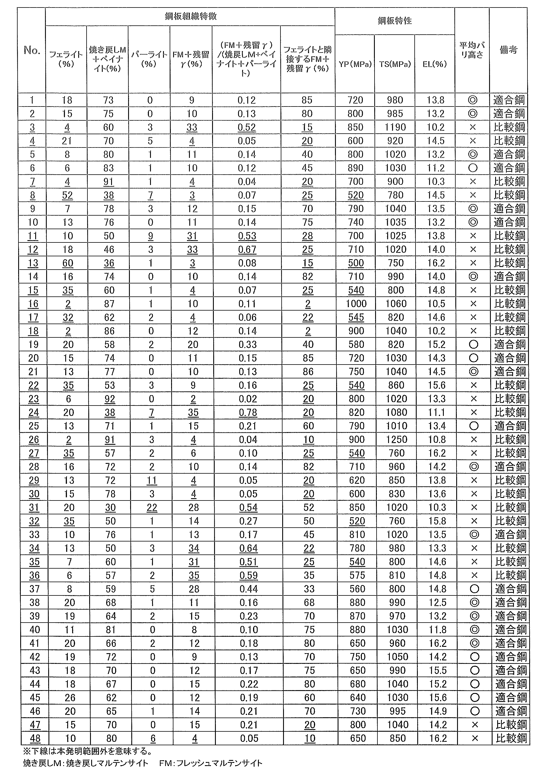
- a slab having the composition shown in Table 1 was hot-rolled, cold-rolled and annealed under the conditions shown in Table 2 to produce a steel sheet.
- the roll diameter used for bending and bending back in the annealing process was 425 mm in radius.
- the steel sheets produced under the conditions shown in Table 2 were immersed in a plating bath to form a hot dip galvanized layer having a coating adhesion amount of 20 to 80 g/m 2 . Further, a part of them was subjected to an alloying treatment after forming the hot-dip galvanized layer to obtain an alloyed hot-dip galvanized steel sheet. After the plating treatment, cooling was performed.
- the material classification is also shown in Table 2.
- the survey method is as follows.
- Area ratio of ferrite, total area ratio of tempered martensite and bainite, total area ratio of fresh martensite and residual ⁇ , ratio of fresh martensite and residual ⁇ adjacent to ferrite among fresh martensite and residual ⁇ was determined by image analysis of the observation result by the scanning electron microscope.
- the area ratio of ferrite was determined by extracting only the ferrite portion in each tissue visual field, determining the area ratio occupied by the ferrite with respect to the observation visual field area, and averaging the area ratio values of the 10 visual fields.
- the total area ratio of tempered martensite and bainite in each observation view, extract only the tempered martensite and bainite portion, and obtain the area ratio occupied by the tempered martensite and bainite with respect to the observation view area. The value was obtained by averaging the area ratio values of 10 fields of view.
- the total area ratio of fresh martensite and residual ⁇ is, in each observation visual field, only the fresh martensite and residual ⁇ portion are extracted, and the area ratio of fresh martensite and residual ⁇ to the observation visual field area is calculated. It was determined by averaging the values of the area ratios of 10 fields of view.
- Ratio of fresh martensite and residual ⁇ of fresh martensite and residual ⁇ adjacent to ferrite is the ratio of fresh martensite and residual ⁇ adjacent to ferrite determined by image analysis in each observation visual field. Then, the value obtained by dividing the value by the total area of fresh martensite and residual ⁇ existing in the observation visual field is "the ratio of fresh martensite and residual ⁇ adjacent to ferrite among fresh martensite and residual ⁇ ". was calculated by averaging the respective ratios of the 10 visual fields. In addition, perlite was confirmed as the other phase.
- All of the examples of the present invention are excellent in suppressing shear burr, and have high El and high ductility, and are excellent in workability.
Landscapes
- Chemical & Material Sciences (AREA)
- Engineering & Computer Science (AREA)
- Materials Engineering (AREA)
- Mechanical Engineering (AREA)
- Metallurgy (AREA)
- Organic Chemistry (AREA)
- Physics & Mathematics (AREA)
- Thermal Sciences (AREA)
- Crystallography & Structural Chemistry (AREA)
- Chemical Kinetics & Catalysis (AREA)
- Oil, Petroleum & Natural Gas (AREA)
- Heat Treatment Of Sheet Steel (AREA)
Abstract
Description
[1]質量%で、C:0.07~0.25%、Si:0.01~1.80%、Mn:1.8~3.2%、P:0.05%以下、S:0.02%以下、Al:0.01~2.0%、N:0.01%以下を含有し、B:0.0001~0.005%、Ti:0.005~0.04%、Nb:0.005~0.06%のいずれか1種以上を含有し、残部がFeおよび不可避的不純物からなる成分組成と、
圧延方向の板厚断面において、フェライトの面積率が5~30%であり、焼き戻しマルテンサイトおよびベイナイトの合計の面積率が40~90%であり、パーライトが0~5%であり、フレッシュマルテンサイトおよび残留γの合計の面積率が5~30%であり、前記フレッシュマルテンサイトおよび前記残留γの合計の面積率の、前記焼き戻しマルテンサイト、ベイナイトおよびパーライトの合計の面積率に対する比が0.5以下であり、前記フレッシュマルテンサイトおよび前記残留γのうち、フェライトと隣接する前記フレッシュマルテンサイトおよび前記残留γの割合が、合計の面積率で30%以上である鋼組織を有し、
降伏強さが550MPa以上である高強度鋼板。
[2]前記成分組成に加えてさらに、質量%で、Mo:0.03~0.50%、Cr:0.1~1.0%のいずれか1種以上を合計で1%以下を含有する[1]に記載の高強度鋼板。
[3]前記成分組成に加えてさらに、質量%で、Cu、Ni、Sn、As、Sb、Ca、Mg、Pb、Co、Ta、W、REM、Zn、V、Sr、Cs、Hfのいずれか1種以上を合計で0.5%以下を含有することを特徴とする[1]または[2]に記載の高強度鋼板。
[4]鋼板表面にめっき層を有する[1]~[3]のいずれかに記載の高強度鋼板。
[5]前記めっき層が、溶融亜鉛めっき層または合金化溶融亜鉛めっき層である[4]に記載も高強度鋼板。
[6][1]~[3]のいずれかに記載の成分組成を有する鋼スラブを熱間圧延後、平均冷却速度が10~30℃/sの条件で冷却し、巻取温度が400~700℃の条件で巻取る熱延工程と、
前記熱延工程で得られた熱延鋼板を冷間圧延する冷延工程と、
前記冷延工程で得られた冷延鋼板を、600℃から焼鈍温度までの温度域において半径800mm以下のロールで曲げ曲げ戻しを合計2回以上5回以下行い、その後750~900℃の焼鈍温度域で焼鈍時間:30~200秒の条件で焼鈍し、前記焼鈍温度から10℃/s以上の平均冷却速度で200~340℃の温度域に冷却し、350~600℃の温度域に再加熱して10~300秒保持する条件で行う焼鈍工程を有する高強度鋼板の製造方法。
[7]前記焼鈍工程後に、めっき処理を行うめっき工程を有する[6]に記載の高強度鋼板の製造方法。
[8]前記めっき処理は、溶融亜鉛めっき処理または合金化溶融亜鉛めっき処理である[7]に記載の高強度鋼板の製造方法。
Cはマルテンサイトを生成させて強度を上昇させるために必要な元素である。所望の降伏強さである550MPa以上の高強度を確保するためには、0.07%以上の含有を必要とする。C量が0.07%未満では、マルテンサイトが生成し、降伏強さが550MPa以上にならない。また、フレッシュマルテンサイトが形成しにくく、バリの発生が顕著となる。一方、C量が0.25%を超えると強度が増加し過ぎるうえに、炭化物が生成しやすくなる。炭化物は加工時のボイド発生の起点となるため、加工性が低下する。したがって、C量は0.07~0.25%の範囲に限定した。好ましくは0.09%以上であり、好ましくは0.20%以下である。より好ましくは0.11%以上であり、より好ましくは0.16%以下である。
Siは固溶強化により鋼板の硬度を高める作用を有する元素である。降伏強さを安定的に確保するために、Siは0.01%以上の含有を必要とする。一方、Siは1.80%を超えると、偏析によりせん断時に偏析に沿った開口が生じやすいうえ、バリの発生も顕著となる。このため、上限を1.80%とする。好ましくは0.3%以上であり、好ましくは1.2%以下である。より好ましくは0.5%以上であり、より好ましくは1.1%以下である。
Mnは鋼板の硬度を高める作用を有する元素である。また、フェライト変態やベイナイト変態などを抑えてマルテンサイトの生成で素材の強度を上昇させる元素である。また、フレッシュマルテンサイトが形成しやすくなるため、バリの発生を抑制できる。このため、Mnは1.8%以上の含有を必要とする。一方、Mn量が多くなると、Mnの偏析が生じやすくなり、加工時に偏析に沿ってボイドが生じやすく加工性が低下するため、Mnの上限は3.2%とする。好ましくは2.3%以上であり、好ましくは3.0%である。より好ましくは2.5%以上であり、より好ましくは2.9以下%である。
Pは粒界に偏析して加工性を低下させる。そのため、Pは0.05%以下とした。好ましくは0.03%以下であり、より好ましくは0.02%以下である。下限については、特に規定しないが、溶製上の経済性から0.0005%以上が好ましい。
Sは、Mnと結合して粗大なMnSを形成し、加工時のボイド発生の起点となるため、S量は低減することが好ましく、Sは0.02%以下であればよい。好ましくは0.01%以下であり、より好ましくは0.002%以下である。下限については、特に規定しないが、溶製上の経済性から0.0001%以上が好ましい。
Alは脱酸剤として作用する元素である。また、Alはセメンタイトの析出を抑制することがあり、その効果を得るために、0.01%以上含有する必要がある。一方、2.0%を超えると、酸化物や窒化物が凝集粗大化して加工時のボイド発生の起点となる。したがって、Alは2.0%以下とした。好ましくは0.03%以上であり、好ましくは0.1%以下である。
Nは本発明においては有害な元素であり、極力低減することが好ましい。NはTiと結合してTiNを形成する。Nが0.01%を超えると、形成されるTiN量が多くなることに起因して加工時のボイド発生の起点となるため、加工性が低下する。したがって、Nは0.01%以下とした。好ましくは0.006%以下である。下限については、特に規定しないが、溶製上の経済性から0.0005%以上が好ましい。
B:0.0001~0.005%
Bはオーステナイト粒界に偏析して、圧延後のフェライト変態を遅延させ、フレッシュマルテンサイトが形成しやすくなる。この効果を十分に得るには、Bの含有量は0.0001%以上にする必要がある。一方、0.005%を超えると、BはFe23(CB)6を形成して加工時のボイド発生の起点となるため、加工性が低下する。このため、Bは0.0001~0.005%の範囲に限定する。
TiはNと結合し、窒化物を形成することにより、BNの形成を抑制し、Bの効果を引き出すとともに、TiNを形成させて結晶粒を微細化して鋼板の高強度化に寄与する。この効果を得るため、Tiの含有量は0.005%以上にする必要がある。一方、0.04%を超えると、粗大なTiを含有する炭化物が生じやすく、所望の引張強さが得られなくなる。このため、Tiは0.005~0.04%の範囲に限定する。
Nbは本発明の効果をさらに向上させる元素である。Nbがマルテンサイト微細化を促進することによりフレッシュマルテンサイトが残りやすく、バリの発生が抑制できる。この効果を得るため、Nbの含有量は0.005%以上にする必要がある。一方、0.06%を超えると、Nb炭化物が析出して加工時のボイド発生の起点となるため、加工性が低下する。このため、Nbは0.06%以下の範囲に限定する。好ましくは0.01%以上であり、好ましくは0.04%以下である。
Moはオーステナイトの核生成を促進し、マルテンサイトを微細化させる。この効果を得るために、Moを含有する場合、0.03%以上とする。一方、Moが粒界偏析すると、フェライトの粒成長が止まるため、フェライト分率が低くなる。これを抑制するため、Moを含有する場合、0.50%以下とする。より好ましくは、0.30%以下である。
Crは焼き戻し脆化を抑制する効果を持つ元素である。そのため、含有させることで本発明の効果はさらに増大する。このため、Crを含有する場合は0.1%以上とする。しかしながら、1.0%を超えての含有はCr炭化物の形成を招き加工性の低下を招く。したがって、Crを含有する場合、1.0%以下とする。
フェライトは、軟質相であり、金属組織を転位密度の低い延性に優れたフェライト結晶粒で構成することが有効である。このような効果を得るためには面積率は5%以上とする。一方、面積率が30%を超えると、フェライトは変形しやすいためせん断時バリの発生が顕著になる。このため、フェライトの面積率は5~30%とする。なお、好ましくは8%以上であり、好ましくは25%以下である。
焼き戻しマルテンサイトおよびベイナイトの硬度はフェライトより高く、フレッシュマルテンサイトより低いため、硬質相と軟質相の間のボイドが発生しにくくなる。このような効果を得るために、面積率は40%以上とする。一方、面積率が90%を超えると、せん断時のバリの発生が顕著になる。このため、焼き戻しマルテンサイトおよびベイナイトの合計の面積率は40~90%とする。なお、好ましくは50%以上であり、好ましくは80%以下である。
パーライトの面積率は5%超えると、せん断時のバリの発生が顕著になるため、パーライトの面積率は0~5%とする。なお、パーライトの面積率に関しては、試験片断面を鏡面研磨、エッチングし、光学顕微鏡を用いて倍率400倍の視野で試験片の圧延断面を写真撮影し、断面写真の画像処理によって求めることができる。
フレッシュマルテンサイトは硬質相であり、せん断時変形しにくいため、バリの発生が抑制できる。本発明の残留γは、少量の歪でもフレッシュマルテンサイトに変態する。このため、バリ発生の抑制効果を得るために、フレッシュマルテンサイトおよび残留γの合計の面積率を5%以上とする。一方、30%を超えると、加工時ボイドが出やすくなり、加工性が低下する。このため、フレッシュマルテンサイトおよび残留γの合計の面積率は5~30%とする。
フレッシュマルテンサイトと残留γ以外の硬質第2相は、焼き戻しマルテンサイト、ベイナイトおよびパーライトである。フレッシュマルテンサイトおよび残留γの合計の面積率と、焼き戻しマルテンサイト、ベイナイトおよびパーライトの合計面積率との比が0.5超えになると、加工時にボイドが発生しやすくなり、加工性が低下する。このため、フレッシュマルテンサイトおよび残留γの合計の面積率の、焼き戻しマルテンサイト、ベイナイトおよびパーライトの合計の面積率に対する比は0.5以下とする。好ましくは0.4以下である。
フェライトと隣接するフレッシュマルテンサイトおよび残留γの合計の割合が、合計の面積率で30%未満になると、バリの発生が顕著になる。このため、フレッシュマルテンサイトおよび残留γのうち、フェライトと隣接するフレッシュマルテンサイトおよび残留γの割合は、合計の面積率で30%以上とする。好ましくは90%以下である。
熱間圧延後、巻取温度までの平均冷却速度が10℃/s未満であると、フェライト粒が成長せず、加工性が低下する。一方、30℃/sを超えると、フェライト粒が成長し過ぎで、せん断中にバリが発生しやすくなる。したがって、平均冷却速度は10~30℃/sである。好ましくは15℃以上であり、好ましくは25℃/s以下である。
巻取温度が400℃を下回ると、ベイナイトなど低温変態相が生成し、フレッシュマルテンサイトが少なく、せん断中のバリが発生しやすくなる。一方、巻取温度が700℃を超えると、フェライト粒径が粗大となり、強度が低下する。したがって、巻取温度は400~700℃である。好ましくは、500℃以上であり、好ましくは600℃以下である。
単純に加熱させるのみでは、所望の鋼組織が得られない。所望の鋼組織が得られないとバリの発生が顕著になる。そこで、所望の鋼組織を得るために、600℃から焼鈍温度までの高温範囲で、曲げと曲げ戻しを行うことにより第2相の核生成を促進する。この曲げ曲げ戻しを行うことで、フレッシュマルテンサイトおよび残留γの合計の面積率の、焼き戻しマルテンサイト、ベイナイトおよびパーライトの合計の面積率に対する比を0.5以下に調整でき、せん断時バリ発生の抑制に関係することを知見した。フレッシュマルテンサイトおよび残留γの合計の面積率の、焼き戻しマルテンサイト、ベイナイトおよびパーライトの合計の面積率に対する比を0.5以下にするためには、ロール径は半径800mm以下とする必要がある。なお、好ましくは、700mm以下である。また、ロール径は、200mm以上であることが好ましい。また、曲げ曲げ戻し回数が5回超えまた2回未満ではフレッシュマルテンサイトおよび残留γの合計の面積率の、焼き戻しマルテンサイト、ベイナイトおよびパーライトの合計の面積率に対する比をは0.5超えになってしまうため、2回以上5回以下とした。好ましくは、4回以下である。なお、曲げ曲げ戻し回数とは、曲げと曲げ戻しを合わせて1回とするのではなく、曲げで1回、曲げ戻しで1回として回数を数える。
焼鈍温度が750℃未満や保持時間が30秒未満の場合、回復の進行が遅くなり、十分なフレッシュマルテンサイト分率が得られない。一方、焼鈍温度が900℃を超えると、フレッシュマルテンサイト分率が高くなり、フェライト分率が低くなり、加工性が低下する。また、焼鈍時間が200秒を超えると、鉄炭化物の多量の析出により加工性の低下を招くことがある。したがって、焼鈍温度は750~900℃であり、好ましくは800℃以上であり、好ましくは900℃以下とする。保持時間は30~200秒であり、好ましくは50秒以上であり、好ましくは150秒以下とする。
平均冷却速度が10℃/s未満になると、フェライト粒が成長し、フェライトの面積率が30%を超える可能性があるため、バリが発生しやすくなる。焼鈍温度から200℃未満の温度域まで冷却すると、フレッシュマルテンサイトと残留γの合計面積率が低くなり、バリが発生しやすくなる。一方、340℃超えの温度域まで冷却すると、フレッシュマルテンサイトと残留γの合計面積率が高くなり、加工性が低下する。したがって、焼鈍温度から200~340℃までの平均冷却速度は10℃/s以上とする。上限については特に定めないが、100℃/s以下が好ましい。
350℃未満の温度域で再加熱すると、フレッシュマルテンサイトおよび残留γが得られなくなり、バリが発生しやすくなる。一方、600℃超えで再加熱すると、フレッシュマルテンサイトと残留γ以外の硬質第2相の面積率が増え、所望のフレッシュマルテンサイトおよび残留γが得られなくなり、バリが発生しやすくなる。再加熱時間(保持時間)が300秒超えになると、生産性上好ましくないうえ、ベイナイト変態が進行し、強度が低下する。一方、再加熱時間(保持時間)が10秒未満になると、フェライトと隣接する前フレッシュマルテンサイトおよび前記残留γの割合が、合計の面積率で30%未満となる。したがって、再加熱温度:350~600℃、保持時間:10~300秒とする。


得られた鋼板の圧延方向の板厚断面を研磨して、1質量%ナイタールによる腐食現出させた。走査型電子顕微鏡で3000倍に拡大して、表面から板厚1/4t部までの領域内を10視野分撮影し、ASTM E 112-10に準拠した切断法によって求める。tは鋼板の厚さ(板厚)である。フェライトは粒内に腐食痕やセメンタイトが観察されない形態を有する組織である。焼き戻しマルテンサイトおよびベイナイトは結晶粒内に多数の微細な鉄系炭化物および腐食痕が認められる組織である。フレッシュマルテンサイト(FM)と残留γは粒内に炭化物が認められず、フェライトよりも明るいコントラストで観察される組織である。
圧延方向と90°の方向を長手方向(引張方向)とするJIS Z 2201に記載の5号試験片を用い、JIS Z 2241に準拠した引張試験を5回行い、平均の降伏強さ(YP)、引張強さ(TS)、突合せ伸び(EL)を求めた。
得られた鋼板から、圧延方向、圧延方向と90°の方向それぞれ50mm×100mmの試験片を採取し、せん断を行い、せん断面のバリ高さを測定した。10回測定して平均バリ高さを求めた。平均バリの高さが5μm以下の場合「◎」と判定し、平均バリの高さが5μm超え15μm未満の場合を「○」と判定し、平均バリの高さが15μm以上の場合を「×」と判定した。
Claims (8)
- 質量%で、C:0.07~0.25%、
Si:0.01~1.80%、
Mn:1.8~3.2%、
P:0.05%以下、
S:0.02%以下、
Al:0.01~2.0%、
N:0.01%以下を含有し、
B:0.0001~0.005%、
Ti:0.005~0.04%、
Nb:0.005~0.06%のいずれか1種以上を含有し、残部がFeおよび不可避的不純物からなる成分組成と、
圧延方向の板厚断面において、フェライトの面積率が5~30%であり、焼き戻しマルテンサイトおよびベイナイトの合計の面積率が40~90%であり、パーライトが0~5%であり、フレッシュマルテンサイトおよび残留γの合計の面積率が5~30%であり、前記フレッシュマルテンサイトおよび前記残留γの合計の面積率の、前記焼き戻しマルテンサイト、ベイナイトおよびパーライトの合計の面積率に対する比が0.5以下であり、前記フレッシュマルテンサイトおよび前記残留γのうち、フェライトと隣接する前記フレッシュマルテンサイトおよび前記残留γの割合が、合計の面積率で30%以上である鋼組織を有し、
降伏強さが550MPa以上である高強度鋼板。 - 前記成分組成に加えてさらに、質量%で、Mo:0.03~0.50%、
Cr:0.1~1.0%のいずれか1種以上を合計で1%以下を含有する請求項1に記載の高強度鋼板。 - 前記成分組成に加えてさらに、質量%で、Cu、Ni、Sn、As、Sb、Ca、Mg、Pb、Co、Ta、W、REM、Zn、V、Sr、Cs、Hfのいずれか1種以上を合計で0.5%以下を含有する請求項1または2に記載の高強度鋼板。
- 鋼板表面にめっき層を有する請求項1~3のいずれか1項に記載の高強度鋼板。
- 前記めっき層が、溶融亜鉛めっき層または合金化溶融亜鉛めっき層である請求項4に記載も高強度鋼板。
- 請求項1~3のいずれか1項に記載の成分組成を有する鋼スラブを熱間圧延後、平均冷却速度が10~30℃/sの条件で冷却し、巻取温度が400~700℃の条件で巻取る熱延工程と、
前記熱延工程で得られた熱延鋼板を冷間圧延する冷延工程と、
前記冷延工程で得られた冷延鋼板を、600℃から焼鈍温度までの温度域において半径800mm以下のロールで曲げ曲げ戻しを合計2回以上5回以下行い、その後750~900℃の焼鈍温度域で焼鈍時間:30~200秒の条件で焼鈍し、前記焼鈍温度から10℃/s以上の平均冷却速度で200~340℃の温度域に冷却し、350~600℃の温度域に再加熱して10~300秒保持する条件で行う焼鈍工程を有する高強度鋼板の製造方法。 - 前記焼鈍工程後に、めっき処理を行うめっき工程を有する請求項6に記載の高強度鋼板の製造方法。
- 前記めっき処理は、溶融亜鉛めっき処理または合金化溶融亜鉛めっき処理である請求項7に記載の高強度鋼板の製造方法。
Priority Applications (7)
| Application Number | Priority Date | Filing Date | Title |
|---|---|---|---|
| MX2021009107A MX2021009107A (es) | 2019-01-30 | 2019-10-18 | Lamina de acero de alta resistencia y metodo para la produccion de la misma. |
| JP2020502498A JP6787522B1 (ja) | 2019-01-30 | 2019-10-18 | 高強度鋼板およびその製造方法 |
| CN201980090657.2A CN113366134B (zh) | 2019-01-30 | 2019-10-18 | 高强度钢板及其制造方法 |
| KR1020217023746A KR102503913B1 (ko) | 2019-01-30 | 2019-10-18 | 고강도 강판 및 그 제조 방법 |
| US17/425,440 US12410491B2 (en) | 2019-01-30 | 2019-10-18 | High-strength steel sheet and method for producing the same |
| EP19912842.2A EP3889283B1 (en) | 2019-01-30 | 2019-10-18 | High-strength steel sheet and method for producing the same |
| US19/297,120 US20250369065A1 (en) | 2019-01-30 | 2025-08-12 | High-strength steel sheet and method for producing the same |
Applications Claiming Priority (2)
| Application Number | Priority Date | Filing Date | Title |
|---|---|---|---|
| JP2019-013796 | 2019-01-30 | ||
| JP2019013796 | 2019-01-30 |
Related Child Applications (2)
| Application Number | Title | Priority Date | Filing Date |
|---|---|---|---|
| US17/425,440 A-371-Of-International US12410491B2 (en) | 2019-01-30 | 2019-10-18 | High-strength steel sheet and method for producing the same |
| US19/297,120 Division US20250369065A1 (en) | 2019-01-30 | 2025-08-12 | High-strength steel sheet and method for producing the same |
Publications (1)
| Publication Number | Publication Date |
|---|---|
| WO2020158065A1 true WO2020158065A1 (ja) | 2020-08-06 |
Family
ID=71840555
Family Applications (1)
| Application Number | Title | Priority Date | Filing Date |
|---|---|---|---|
| PCT/JP2019/041131 Ceased WO2020158065A1 (ja) | 2019-01-30 | 2019-10-18 | 高強度鋼板およびその製造方法 |
Country Status (7)
| Country | Link |
|---|---|
| US (2) | US12410491B2 (ja) |
| EP (1) | EP3889283B1 (ja) |
| JP (1) | JP6787522B1 (ja) |
| KR (1) | KR102503913B1 (ja) |
| CN (1) | CN113366134B (ja) |
| MX (1) | MX2021009107A (ja) |
| WO (1) | WO2020158065A1 (ja) |
Cited By (7)
| Publication number | Priority date | Publication date | Assignee | Title |
|---|---|---|---|---|
| WO2022202716A1 (ja) * | 2021-03-23 | 2022-09-29 | Jfeスチール株式会社 | 亜鉛めっき鋼板および部材、ならびに、それらの製造方法 |
| JP7197062B1 (ja) * | 2021-07-28 | 2022-12-27 | Jfeスチール株式会社 | 亜鉛めっき鋼板および部材、ならびに、それらの製造方法 |
| WO2023007833A1 (ja) * | 2021-07-28 | 2023-02-02 | Jfeスチール株式会社 | 亜鉛めっき鋼板および部材、ならびに、それらの製造方法 |
| WO2023032339A1 (ja) * | 2021-08-31 | 2023-03-09 | 日本製鉄株式会社 | 鋼板及びその製造方法 |
| JP2023551501A (ja) * | 2020-12-03 | 2023-12-08 | ポスコ カンパニー リミテッド | 曲げ加工性に優れた超高強度冷延鋼板及びその製造方法 |
| JP2024535898A (ja) * | 2021-09-24 | 2024-10-02 | ポスコ カンパニー リミテッド | 表面品質に優れ、材質偏差が少ない高強度冷延鋼板及びこの製造方法 |
| EP4194578A4 (en) * | 2020-10-13 | 2025-05-21 | JFE Steel Corporation | HIGH-STRENGTH COLD-ROLLED STEEL SHEET, HIGH-STRENGTH CLAD STEEL SHEET, METHOD FOR PRODUCING A HIGH-STRENGTH COLD-ROLLED STEEL SHEET, AND METHOD FOR PRODUCING A HIGH-STRENGTH CLAD STEEL SHEET |
Families Citing this family (2)
| Publication number | Priority date | Publication date | Assignee | Title |
|---|---|---|---|---|
| US12410491B2 (en) | 2019-01-30 | 2025-09-09 | Jfe Steel Corporation | High-strength steel sheet and method for producing the same |
| EP3889282B1 (en) * | 2019-01-30 | 2024-03-20 | JFE Steel Corporation | High-strength steel sheet and method for producing the same |
Citations (8)
| Publication number | Priority date | Publication date | Assignee | Title |
|---|---|---|---|---|
| JPH04120242A (ja) | 1990-09-11 | 1992-04-21 | Nippon Steel Corp | プレス成形時の耐バリ性、絞り性に優れた冷延鋼板およびその製造方法 |
| JP2011111673A (ja) | 2009-11-30 | 2011-06-09 | Nippon Steel Corp | 機械切断特性に優れた引張最大強度900MPa以上の高強度冷延鋼板及びその製造方法、並びに、高強度亜鉛めっき鋼板及びその製造方法 |
| JP2011168880A (ja) | 2010-01-22 | 2011-09-01 | Jfe Steel Corp | 耐バリ性に優れた高強度溶融亜鉛めっき鋼板およびその製造方法 |
| WO2013018739A1 (ja) * | 2011-07-29 | 2013-02-07 | 新日鐵住金株式会社 | 曲げ性に優れた高強度亜鉛めっき鋼板およびその製造方法 |
| WO2013018726A1 (ja) * | 2011-07-29 | 2013-02-07 | 新日鐵住金株式会社 | 合金化溶融亜鉛めっき層およびそれを有する鋼板ならびにその製造方法 |
| JP5354135B2 (ja) | 2011-09-30 | 2013-11-27 | 新日鐵住金株式会社 | 機械切断特性に優れた高強度溶融亜鉛めっき鋼板、高強度合金化溶融亜鉛めっき鋼板、並びにそれらの製造方法 |
| JP2016141858A (ja) * | 2015-02-03 | 2016-08-08 | Jfeスチール株式会社 | 高強度鋼板、高強度めっき鋼板、高強度溶融亜鉛めっき鋼板および高強度合金化溶融亜鉛めっき鋼板、並びにそれらの製造方法 |
| WO2017108959A1 (en) * | 2015-12-21 | 2017-06-29 | Arcelormittal | Method for producing a high strength coated steel sheet having improved ductility and formability, and obtained coated steel sheet |
Family Cites Families (23)
| Publication number | Priority date | Publication date | Assignee | Title |
|---|---|---|---|---|
| JP5365217B2 (ja) | 2008-01-31 | 2013-12-11 | Jfeスチール株式会社 | 高強度鋼板およびその製造方法 |
| JP4924730B2 (ja) | 2009-04-28 | 2012-04-25 | Jfeスチール株式会社 | 加工性、溶接性および疲労特性に優れる高強度溶融亜鉛めっき鋼板およびその製造方法 |
| MX360965B (es) | 2009-11-30 | 2018-11-23 | Nippon Steel & Sumitomo Metal Corp | Placa de acero de alta resistencia con resistencia a la tracción final de 900 mpa o mas, excelente en resistencia a la fragilizacion por hidrógeno y método de producción de la misma. |
| JP5141811B2 (ja) * | 2010-11-12 | 2013-02-13 | Jfeスチール株式会社 | 均一伸びとめっき性に優れた高強度溶融亜鉛めっき鋼板およびその製造方法 |
| US9551055B2 (en) | 2011-09-30 | 2017-01-24 | Nippon Steel & Sumitomo Metal Corporation | Process for producing high-strength hot-dip galvanized steel sheet |
| CN103842542B (zh) * | 2011-09-30 | 2016-01-20 | 新日铁住金株式会社 | 耐冲击特性优良的高强度热浸镀锌钢板及其制造方法、和高强度合金化热浸镀锌钢板及其制造方法 |
| ES2712809T3 (es) * | 2011-09-30 | 2019-05-14 | Nippon Steel & Sumitomo Metal Corp | Chapa de acero galvanizada y su método de fabricación |
| JP5958667B1 (ja) | 2014-12-22 | 2016-08-02 | Jfeスチール株式会社 | 高強度溶融亜鉛めっき鋼板およびその製造方法 |
| JP6052472B2 (ja) * | 2015-01-15 | 2016-12-27 | Jfeスチール株式会社 | 高強度溶融亜鉛めっき鋼板およびその製造方法 |
| EP3219821B1 (en) | 2015-01-15 | 2019-11-13 | JFE Steel Corporation | High-strength galvanized steel sheet and method for producing the same |
| JP6492869B2 (ja) | 2015-03-30 | 2019-04-03 | 新日鐵住金株式会社 | 溶接性と加工性に優れた高強度冷延鋼板とその製造方法 |
| WO2016198906A1 (fr) * | 2015-06-10 | 2016-12-15 | Arcelormittal | Acier a haute résistance et procédé de fabrication |
| JP6610113B2 (ja) * | 2015-09-16 | 2019-11-27 | 日本製鉄株式会社 | 高強度合金化溶融亜鉛めっき鋼板と該鋼板用熱延鋼板及びそれらの製造方法 |
| JP6288394B2 (ja) | 2016-03-25 | 2018-03-07 | 新日鐵住金株式会社 | 高強度鋼板および高強度亜鉛めっき鋼板 |
| US10920294B2 (en) | 2016-03-31 | 2021-02-16 | Jfe Steel Corporation | Steel sheet, coated steel sheet, method for producing hot-rolled steel sheet, method for producing full-hard cold-rolled steel sheet, method for producing heat-treated sheet, method for producing steel sheet, and method for producing coated steel sheet |
| KR102245008B1 (ko) | 2016-08-30 | 2021-04-26 | 제이에프이 스틸 가부시키가이샤 | 고강도 강판 및 그 제조 방법 |
| CN109642290B (zh) | 2016-09-30 | 2022-05-03 | 杰富意钢铁株式会社 | 高强度镀覆钢板及其制造方法 |
| JP6414246B2 (ja) | 2017-02-15 | 2018-10-31 | Jfeスチール株式会社 | 高強度鋼板およびその製造方法 |
| EP3556881B1 (en) | 2017-02-28 | 2020-09-30 | JFE Steel Corporation | High-strength steel sheet and production method therefor |
| JP6315154B1 (ja) | 2017-07-31 | 2018-04-25 | 新日鐵住金株式会社 | 溶融亜鉛めっき鋼板 |
| EP3653745A4 (en) | 2017-10-20 | 2020-07-15 | JFE Steel Corporation | HIGH-STRENGTH STEEL SHEET AND MANUFACTURING METHOD THEREOF |
| MX2020004029A (es) | 2017-10-20 | 2020-08-13 | Jfe Steel Corp | Lamina de acero de alta resistencia y metodo para la fabricacion de la misma. |
| US12410491B2 (en) | 2019-01-30 | 2025-09-09 | Jfe Steel Corporation | High-strength steel sheet and method for producing the same |
-
2019
- 2019-10-18 US US17/425,440 patent/US12410491B2/en active Active
- 2019-10-18 WO PCT/JP2019/041131 patent/WO2020158065A1/ja not_active Ceased
- 2019-10-18 CN CN201980090657.2A patent/CN113366134B/zh active Active
- 2019-10-18 MX MX2021009107A patent/MX2021009107A/es unknown
- 2019-10-18 KR KR1020217023746A patent/KR102503913B1/ko active Active
- 2019-10-18 EP EP19912842.2A patent/EP3889283B1/en active Active
- 2019-10-18 JP JP2020502498A patent/JP6787522B1/ja active Active
-
2025
- 2025-08-12 US US19/297,120 patent/US20250369065A1/en active Pending
Patent Citations (8)
| Publication number | Priority date | Publication date | Assignee | Title |
|---|---|---|---|---|
| JPH04120242A (ja) | 1990-09-11 | 1992-04-21 | Nippon Steel Corp | プレス成形時の耐バリ性、絞り性に優れた冷延鋼板およびその製造方法 |
| JP2011111673A (ja) | 2009-11-30 | 2011-06-09 | Nippon Steel Corp | 機械切断特性に優れた引張最大強度900MPa以上の高強度冷延鋼板及びその製造方法、並びに、高強度亜鉛めっき鋼板及びその製造方法 |
| JP2011168880A (ja) | 2010-01-22 | 2011-09-01 | Jfe Steel Corp | 耐バリ性に優れた高強度溶融亜鉛めっき鋼板およびその製造方法 |
| WO2013018739A1 (ja) * | 2011-07-29 | 2013-02-07 | 新日鐵住金株式会社 | 曲げ性に優れた高強度亜鉛めっき鋼板およびその製造方法 |
| WO2013018726A1 (ja) * | 2011-07-29 | 2013-02-07 | 新日鐵住金株式会社 | 合金化溶融亜鉛めっき層およびそれを有する鋼板ならびにその製造方法 |
| JP5354135B2 (ja) | 2011-09-30 | 2013-11-27 | 新日鐵住金株式会社 | 機械切断特性に優れた高強度溶融亜鉛めっき鋼板、高強度合金化溶融亜鉛めっき鋼板、並びにそれらの製造方法 |
| JP2016141858A (ja) * | 2015-02-03 | 2016-08-08 | Jfeスチール株式会社 | 高強度鋼板、高強度めっき鋼板、高強度溶融亜鉛めっき鋼板および高強度合金化溶融亜鉛めっき鋼板、並びにそれらの製造方法 |
| WO2017108959A1 (en) * | 2015-12-21 | 2017-06-29 | Arcelormittal | Method for producing a high strength coated steel sheet having improved ductility and formability, and obtained coated steel sheet |
Cited By (12)
| Publication number | Priority date | Publication date | Assignee | Title |
|---|---|---|---|---|
| EP4194578A4 (en) * | 2020-10-13 | 2025-05-21 | JFE Steel Corporation | HIGH-STRENGTH COLD-ROLLED STEEL SHEET, HIGH-STRENGTH CLAD STEEL SHEET, METHOD FOR PRODUCING A HIGH-STRENGTH COLD-ROLLED STEEL SHEET, AND METHOD FOR PRODUCING A HIGH-STRENGTH CLAD STEEL SHEET |
| US12404565B2 (en) | 2020-10-13 | 2025-09-02 | Jfe Steel Corporation | High-strength cold-rolled steel sheet, high-strength coated or plated steel sheet, method of producing high-strength cold-rolled steel sheet, and method of producing high-strength coated or plated steel sheet |
| JP2023551501A (ja) * | 2020-12-03 | 2023-12-08 | ポスコ カンパニー リミテッド | 曲げ加工性に優れた超高強度冷延鋼板及びその製造方法 |
| JP7576704B2 (ja) | 2020-12-03 | 2024-10-31 | ポスコ カンパニー リミテッド | 曲げ加工性に優れた超高強度冷延鋼板及びその製造方法 |
| WO2022202716A1 (ja) * | 2021-03-23 | 2022-09-29 | Jfeスチール株式会社 | 亜鉛めっき鋼板および部材、ならびに、それらの製造方法 |
| JP7197063B1 (ja) * | 2021-03-23 | 2022-12-27 | Jfeスチール株式会社 | 亜鉛めっき鋼板および部材、ならびに、それらの製造方法 |
| JP7197062B1 (ja) * | 2021-07-28 | 2022-12-27 | Jfeスチール株式会社 | 亜鉛めっき鋼板および部材、ならびに、それらの製造方法 |
| WO2023007833A1 (ja) * | 2021-07-28 | 2023-02-02 | Jfeスチール株式会社 | 亜鉛めっき鋼板および部材、ならびに、それらの製造方法 |
| WO2023032339A1 (ja) * | 2021-08-31 | 2023-03-09 | 日本製鉄株式会社 | 鋼板及びその製造方法 |
| JPWO2023032339A1 (ja) * | 2021-08-31 | 2023-03-09 | ||
| JP7674676B2 (ja) | 2021-08-31 | 2025-05-12 | 日本製鉄株式会社 | 鋼板及びその製造方法 |
| JP2024535898A (ja) * | 2021-09-24 | 2024-10-02 | ポスコ カンパニー リミテッド | 表面品質に優れ、材質偏差が少ない高強度冷延鋼板及びこの製造方法 |
Also Published As
| Publication number | Publication date |
|---|---|
| CN113366134A (zh) | 2021-09-07 |
| EP3889283A1 (en) | 2021-10-06 |
| JPWO2020158065A1 (ja) | 2021-02-18 |
| KR20210107820A (ko) | 2021-09-01 |
| CN113366134B (zh) | 2022-07-19 |
| EP3889283B1 (en) | 2024-02-28 |
| US20250369065A1 (en) | 2025-12-04 |
| JP6787522B1 (ja) | 2020-11-18 |
| KR102503913B1 (ko) | 2023-02-27 |
| EP3889283A4 (en) | 2022-03-23 |
| US12410491B2 (en) | 2025-09-09 |
| US20220098696A1 (en) | 2022-03-31 |
| MX2021009107A (es) | 2021-09-14 |
Similar Documents
| Publication | Publication Date | Title |
|---|---|---|
| JP6354921B1 (ja) | 鋼板およびその製造方法 | |
| JP6787522B1 (ja) | 高強度鋼板およびその製造方法 | |
| CN109563582B (zh) | 薄钢板及其制造方法 | |
| JP6787523B1 (ja) | 高強度鋼板およびその製造方法 | |
| CN108884538B (zh) | 薄钢板和镀覆钢板、以及薄钢板和镀覆钢板的制造方法 | |
| JP5987999B1 (ja) | 高強度鋼板およびその製造方法 | |
| JP6278162B1 (ja) | 薄鋼板およびめっき鋼板、並びに熱延鋼板の製造方法、冷延フルハード鋼板の製造方法、薄鋼板の製造方法およびめっき鋼板の製造方法 | |
| WO2013121963A1 (ja) | 鋼板、めっき鋼板、及びそれらの製造方法 | |
| JP5076394B2 (ja) | 高張力鋼板ならびにその製造方法 | |
| JP6275510B2 (ja) | 高強度熱延鋼板およびその製造方法 | |
| CN116018416B (zh) | 钢板及其制造方法 | |
| JP2014009372A (ja) | 曲げ性に優れた高強度熱延鋼板およびその製造方法 | |
| JP2018090893A (ja) | 熱延鋼板の製造方法および冷延フルハード鋼板の製造方法 | |
| JP6278161B1 (ja) | 薄鋼板およびめっき鋼板、並びに、熱延鋼板の製造方法、冷延フルハード鋼板の製造方法、薄鋼板の製造方法およびめっき鋼板の製造方法 | |
| CN116323993B (zh) | 高强度冷轧钢板、高强度镀覆钢板、高强度冷轧钢板的制造方法、高强度镀覆钢板的制造方法以及汽车部件 | |
| JP5978614B2 (ja) | 打ち抜き性に優れた高強度熱延鋼板およびその製造方法 | |
| JP4501699B2 (ja) | 深絞り性と伸びフランジ性に優れた高強度鋼板およびその製造方法 | |
| JP6320792B2 (ja) | 高強度熱延鋼板およびその製造方法 | |
| CN111868282B (zh) | 钢板 | |
| JP6453140B2 (ja) | 切断端面の耐遅れ破壊性に優れた高強度鋼板およびその製造方法 | |
| JP5861434B2 (ja) | 打ち抜き性に優れた高強度熱延鋼板およびその製造方法 | |
| JP6086078B2 (ja) | 伸びフランジ性に優れた高強度冷延鋼板およびその製造方法 | |
| KR102964359B1 (ko) | 고강도 강판 및 그의 제조 방법 |
Legal Events
| Date | Code | Title | Description |
|---|---|---|---|
| ENP | Entry into the national phase |
Ref document number: 2020502498 Country of ref document: JP Kind code of ref document: A |
|
| 121 | Ep: the epo has been informed by wipo that ep was designated in this application |
Ref document number: 19912842 Country of ref document: EP Kind code of ref document: A1 |
|
| ENP | Entry into the national phase |
Ref document number: 2019912842 Country of ref document: EP Effective date: 20210628 |
|
| ENP | Entry into the national phase |
Ref document number: 20217023746 Country of ref document: KR Kind code of ref document: A |
|
| WWE | Wipo information: entry into national phase |
Ref document number: MX/A/2021/009107 Country of ref document: MX |
|
| NENP | Non-entry into the national phase |
Ref country code: DE |
|
| WWP | Wipo information: published in national office |
Ref document number: MX/A/2021/009107 Country of ref document: MX |
|
| WWG | Wipo information: grant in national office |
Ref document number: 17425440 Country of ref document: US |
|
| WWG | Wipo information: grant in national office |
Ref document number: MX/A/2021/009107 Country of ref document: MX |