WO2020158848A1 - Outil d'alignement de fibre optique et procédé de réglage de fibre optique dans un support de fibre - Google Patents
Outil d'alignement de fibre optique et procédé de réglage de fibre optique dans un support de fibre Download PDFInfo
- Publication number
- WO2020158848A1 WO2020158848A1 PCT/JP2020/003365 JP2020003365W WO2020158848A1 WO 2020158848 A1 WO2020158848 A1 WO 2020158848A1 JP 2020003365 W JP2020003365 W JP 2020003365W WO 2020158848 A1 WO2020158848 A1 WO 2020158848A1
- Authority
- WO
- WIPO (PCT)
- Prior art keywords
- optical fibers
- fiber
- optical
- optical fiber
- aligning
- Prior art date
- Legal status (The legal status is an assumption and is not a legal conclusion. Google has not performed a legal analysis and makes no representation as to the accuracy of the status listed.)
- Ceased
Links
Images


Classifications
-
- G—PHYSICS
- G02—OPTICS
- G02B—OPTICAL ELEMENTS, SYSTEMS OR APPARATUS
- G02B6/00—Light guides; Structural details of arrangements comprising light guides and other optical elements, e.g. couplings
- G02B6/24—Coupling light guides
- G02B6/255—Splicing of light guides, e.g. by fusion or bonding
- G02B6/2555—Alignment or adjustment devices for aligning prior to splicing
-
- G—PHYSICS
- G02—OPTICS
- G02B—OPTICAL ELEMENTS, SYSTEMS OR APPARATUS
- G02B6/00—Light guides; Structural details of arrangements comprising light guides and other optical elements, e.g. couplings
- G02B6/24—Coupling light guides
- G02B6/36—Mechanical coupling means
- G02B6/38—Mechanical coupling means having fibre to fibre mating means
- G02B6/3807—Dismountable connectors, i.e. comprising plugs
- G02B6/3898—Tools, e.g. handheld; Tuning wrenches; Jigs used with connectors, e.g. for extracting, removing or inserting in a panel, for engaging or coupling connectors, for assembling or disassembling components within the connector, for applying clips to hold two connectors together or for crimping
-
- G—PHYSICS
- G02—OPTICS
- G02B—OPTICAL ELEMENTS, SYSTEMS OR APPARATUS
- G02B6/00—Light guides; Structural details of arrangements comprising light guides and other optical elements, e.g. couplings
- G02B6/24—Coupling light guides
- G02B6/36—Mechanical coupling means
- G02B6/38—Mechanical coupling means having fibre to fibre mating means
- G02B6/3807—Dismountable connectors, i.e. comprising plugs
- G02B6/3873—Connectors using guide surfaces for aligning ferrule ends, e.g. tubes, sleeves, V-grooves, rods, pins, balls
- G02B6/3885—Multicore or multichannel optical connectors, i.e. one single ferrule containing more than one fibre, e.g. ribbon type
Definitions
- the present invention relates to an optical fiber alignment tool and a method for setting an optical fiber in a fiber holder.
- field assembly type optical connectors have been proposed that can be easily assembled to optical fiber cord terminals at optical fiber installation sites.
- the built-in optical fiber is preliminarily inserted and fixed in the ferrule at the factory, and the end of the built-in optical fiber and the end of the optical fiber in the optical fiber cord are fused together.
- Patent Document 1 a ferrule having a plurality of built-in optical fibers is assembled by fusion-splicing the ends of the plurality of built-in optical fibers and the ends of the plurality of optical fibers in an optical fiber cord.
- a fusion splicing type field assembly type optical connector is disclosed (see FIGS. 41 and 42 of Patent Document 1).
- the present invention aims to improve the workability of the work of aligning and holding a plurality of optical fibers in a predetermined order.
- Some embodiments of the present invention are an optical fiber alignment tool for aligning a plurality of optical fibers, the fiber aligning unit aligning the plurality of optical fibers in a predetermined order, and maintaining the predetermined order.
- the optical fiber aligning tool further comprising: a fiber holding portion that holds the plurality of optical fibers in a line in a direction in which the plurality of optical fibers are arranged.
- FIG. 1A and 1B are perspective views of the optical fiber alignment tool 10 according to the first embodiment in an initial state.
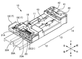
- FIG. 2 is a perspective view of the optical fiber alignment tool 10 according to the first embodiment in an assembled state.
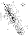
- FIG. 3 is an exploded perspective view of the main body 12 in an initial state.
- 4A to 4D are explanatory views showing the states before and after assembling a plurality of optical fibers 1 by the optical fiber alignment tool 10 of the first embodiment.
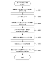
- FIG. 5 is a flowchart of a method (setting procedure) for setting the plurality of optical fibers 1 on the fiber holder 6 by the optical fiber alignment tool 10 of the first embodiment.
- FIG. 6A is a perspective view showing a state where the optical fiber 1 is inserted into the fiber insertion portion 22.
- FIG. 6B is a perspective view showing a state in which a plurality of optical fibers 1 are assembled.
- 7A to 7C are explanatory views showing a state in which a plurality of optical fibers 1 are inserted into the fiber insertion portion 22 of the optical fiber alignment tool 10 of the first comparative example.
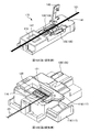
- FIG. 8 is a perspective view of the optical fiber alignment tool 110 according to the second embodiment in an initial state.
- FIG. 9 is a perspective view of the optical fiber alignment tool 110 according to the second embodiment in an assembled state.
- FIG. 10 is an exploded perspective view of the main body 111 in the initial state.
- FIG. 11 is an exploded perspective view of the main body 111 in the assembled state.
- FIG. 12A to 12D are explanatory views showing a state before and after assembling a plurality of optical fibers 101 by the optical fiber alignment tool 110 of the second embodiment.
- FIG. 13A is a schematic explanatory diagram of the main body 111 in an initial state.
- FIG. 13B is a schematic explanatory diagram of the main body 111 in the assembled state.
- FIG. 14A is an explanatory diagram showing the main body 111 in the assembled state, with the main body side cover 119 closed.
- FIG. 14B is an explanatory diagram showing the main body 111 in the assembled state with the main body side cover 119 opened.
- FIG. 15A is a perspective view showing a state where the optical fiber 101 is inserted into the fiber insertion portion 122.
- FIG. 15B is a perspective view showing a state in which a plurality of optical fibers 101 are assembled.
- FIG. 16A is a perspective view showing a state in which a plurality of optical fibers 101 are accommodated in the V groove 107 of the fiber holder 106.
- FIG. 16B is a perspective view showing how the lid 108 of the fiber holder 106 is closed.
- 17A to 17C are explanatory views showing a state in which a plurality of optical fibers 101 are inserted into the fiber insertion portion 122 in the optical fiber alignment tool 110 of the second comparative example.
- FIG. 18A is a perspective view of the optical fiber alignment tool 110 of the first modified example.
- FIG. 18B is a perspective view of the main body 111 of the optical fiber alignment tool 110 of the second modification.
- An optical fiber aligning tool for aligning a plurality of optical fibers, the fiber aligning unit aligning the plurality of optical fibers in a predetermined order, and the plurality of optical fibers while maintaining the predetermined order. It becomes clear that the optical fiber aligning tool is characterized by having a fiber holding portion that holds the plurality of optical fibers in a direction in which the optical fibers are arranged. According to such an optical fiber alignment tool, it is possible to improve the workability of the work of aligning and holding a plurality of optical fibers in a predetermined order.
- the fiber alignment section includes a plurality of separation sections provided in a direction in which the plurality of optical fibers are arranged. Thereby, the plurality of optical fibers can be aligned in a predetermined order.
- the fiber aligning section includes a plurality of fiber inserting sections provided between the two separating sections, and that the optical fibers are inserted one by one into the plurality of fiber inserting sections. Thereby, the plurality of optical fibers can be aligned in a predetermined order.
- a taper portion is formed on the side of the fiber insertion portion where the optical fiber is inserted.
- the optical fiber can be easily inserted into the fiber insertion portion.
- the fiber holding section includes a mounting section on which the plurality of optical fibers are mounted when the fiber holding section sandwiches and holds the plurality of optical fibers in a direction in which the plurality of optical fibers are arranged. Accordingly, it is possible to hold the plurality of optical fibers by sandwiching the plurality of optical fibers in the direction in which the plurality of optical fibers are arranged while maintaining the predetermined order of the plurality of optical fibers.
- the fiber holding unit When the fiber holding unit holds the plurality of optical fibers in a direction in which the plurality of optical fibers are arranged, the fiber holding unit is arranged in a direction perpendicular to an optical axis direction of the optical fibers and a direction in which the plurality of optical fibers are arranged. It is desirable to sandwich a plurality of optical fibers. Accordingly, it is possible to hold the plurality of optical fibers by sandwiching the plurality of optical fibers in the direction in which the plurality of optical fibers are arranged while maintaining the predetermined order of the plurality of optical fibers.
- the plurality of optical fibers is preferably movable in the direction in which the plurality of optical fibers are arranged. .. Accordingly, it is possible to hold the plurality of optical fibers by sandwiching the plurality of optical fibers in the direction in which the plurality of optical fibers are arranged while maintaining the predetermined order of the plurality of optical fibers.
- the plurality of optical fibers be movable in a direction in which the plurality of optical fibers are arranged, by the separation portion not protruding from the mounting surfaces of the plurality of optical fibers in the mounting portion. .. Accordingly, it is possible to hold the plurality of optical fibers by sandwiching the plurality of optical fibers in the direction in which the plurality of optical fibers are arranged while maintaining the predetermined order of the plurality of optical fibers.
- a holder holder is further provided, and a fiber holder that holds the plurality of optical fibers in the predetermined order is installed in the holder holder.
- a fiber holder that holds the plurality of optical fibers in the predetermined order is installed in the holder holder.
- a front side holding section for holding the plurality of optical fibers
- the holder holding section is preferably provided so as to be sandwiched between the fiber alignment section and the front side holding section.
- optical fiber alignment tools for solving these problems. That is, it is an optical fiber alignment tool for aligning a plurality of optical fibers, the fiber aligning unit for aligning the plurality of optical fibers in a predetermined order, and the optical fiber alignment tool while maintaining the predetermined order of the plurality of optical fibers. And a fiber holding unit that collects and holds a plurality of optical fibers, wherein the fiber alignment unit includes a separation unit that separates the optical fibers aligned in the predetermined order from each other, and the separation unit is the An optical fiber aligning tool characterized by being retractable from between optical fibers becomes clear. According to such an optical fiber alignment tool, it is possible to improve the workability of the work of aligning and holding a plurality of optical fibers in a predetermined order and a predetermined pitch.
- the separating section retracts from between the optical fibers so that the fiber holding section can hold the plurality of optical fibers in a direction in which the plurality of optical fibers are aligned. Thereby, a plurality of optical fibers can be held at a predetermined pitch.
- the fiber alignment section includes a plurality of fiber insertion sections provided between the two separation sections, and the optical fiber is inserted into the fiber insertion section. Thereby, the plurality of optical fibers can be aligned in a predetermined order.
- the fiber insertion part is formed so as to widen toward the side where the optical fiber is inserted. Thereby, the optical fiber can be easily inserted into the fiber insertion portion.
- the fiber holding section includes an arm section, and the arm section is provided both before the separation section retracts from between the optical fibers and after the separation section retracts from between the optical fibers. It is desirable that the plurality of optical fibers be mounted. This allows the plurality of optical fibers to move in the direction in which the plurality of optical fibers are aligned while maintaining the predetermined order of the plurality of optical fibers.
- the fiber holding unit When the fiber holding unit holds the plurality of optical fibers in a direction in which the plurality of optical fibers are aligned, the fiber holding unit is perpendicular to both the optical axis direction of the optical fibers and the direction in which the plurality of optical fibers are aligned. It is desirable that the plurality of optical fibers be sandwiched in different directions. This allows the plurality of optical fibers to move in the direction in which the plurality of optical fibers are aligned while maintaining the predetermined order of the plurality of optical fibers.
- the plurality of optical fibers are movable in the direction in which the plurality of optical fibers are aligned. Is desirable.
- the plurality of optical fibers can be gathered in the direction in which the plurality of optical fibers are aligned while maintaining the predetermined order of the plurality of optical fibers.
- the plurality of optical fibers can be moved in a direction in which the plurality of optical fibers are aligned after the separating unit is retracted from between the optical fibers.
- the plurality of optical fibers can be gathered in the direction in which the plurality of optical fibers are aligned while maintaining the predetermined order of the plurality of optical fibers.
- a holder holder is further provided, and a fiber holder that holds the plurality of optical fibers in the predetermined order and a predetermined pitch is installed in the holder holder.
- a fiber holder that holds the plurality of optical fibers in the predetermined order and a predetermined pitch is installed in the holder holder.
- a front side holding section for holding the plurality of optical fibers
- the holder mounting section is preferably provided so as to be sandwiched between the fiber alignment section and the front side holding section.
- a method for setting an optical fiber in a fiber holder using an optical fiber alignment tool for aligning a plurality of optical fibers wherein the optical fiber alignment tool comprises: A fiber aligning unit that aligns the fibers in a predetermined order; and a fiber holding unit that collects and holds the plurality of optical fibers while maintaining the predetermined order of the plurality of optical fibers, and the fiber aligning unit is A separation unit that separates the optical fibers arranged in the predetermined order from each other, and the plurality of optical fibers are arranged in the predetermined order, and the separation unit retracts from between the optical fibers.
- the method of setting the optical fiber in the fiber holder is characterized by According to such a method of setting the optical fibers in the fiber holder, it is possible to improve the workability of the work of aligning and holding the plurality of optical fibers in a predetermined order and a predetermined pitch.
- An optical fiber aligning tool for aligning a plurality of optical fibers, the fiber aligning unit aligning the plurality of optical fibers in a predetermined order, and maintaining the predetermined order of the plurality of optical fibers.
- a fiber holding unit that collects and holds the plurality of optical fibers, and the fiber alignment unit includes a separation unit that separates the optical fibers arranged in the predetermined order from each other. Is retractable from between the optical fibers, and the fiber holding portion is a position where the separating portion separates the optical fibers again after the separating portion retracts from between the optical fibers.
- the optical fiber aligning tool which is characterized in that it has a stopper portion for restricting the return to the above, becomes clear. According to such an optical fiber alignment tool, it is possible to prevent the optical fiber from being damaged by the separating section sandwiching the optical fiber.
- the fiber holding unit collects and holds the plurality of optical fibers in a direction in which the plurality of optical fibers are aligned, it is perpendicular to both the optical axis direction of the optical fibers and the direction in which the plurality of optical fibers are aligned. It is preferable that the plurality of optical fibers are sandwiched in different directions, and the stopper portion regulates movement of the separation portion in a direction in which the plurality of optical fibers are sandwiched. As a result, it is possible to prevent the optical fiber from being sandwiched by the separating section and damaging the optical fiber.
- the fiber holding unit includes a slide unit that collects and holds the plurality of optical fibers after the separation unit is retracted from between the optical fibers, and the stopper unit includes a slide unit in which the slide unit includes the separation unit. It is desirable to regulate returning to a position separating the optical fibers from each other again. As a result, it is possible to prevent the optical fiber from being sandwiched by the separating section and damaging the optical fiber.
- the fiber holding portion includes a lid portion that sandwiches the plurality of optical fibers in a direction perpendicular to both an optical axis direction of the optical fiber and a direction in which the plurality of optical fibers are aligned, and the lid portion is a convex portion.
- the slide part includes a locking part, and the locking part locks with the convex part when the separation part moves in a direction in which the plurality of optical fibers are sandwiched. ..
- the slide part includes a locking part, and the locking part locks with the convex part when the separation part moves in a direction in which the plurality of optical fibers are sandwiched. ..
- FIG. 2 is a perspective view of the optical fiber alignment tool 10 according to the first embodiment in an assembled state. 1B and 2, part of the housing 11 of the optical fiber alignment tool 10 is omitted.
- the optical axis direction of the optical fiber 1 held by the optical fiber alignment tool 10 is the front-back direction.
- the main body portion 12, the holder holding portion 13, and the front holding portion 14 are provided in this order in the front-rear direction, and the holder holding portion 13 is provided.
- the side of the front side holding portion 14 with respect to is referred to as “front”, and the side of the main body portion 12 with respect to the holder holding portion 13 is referred to as “rear”.
- the direction perpendicular to the bottom surface of the accommodating portion 43 of the holder holding portion 13 is referred to as “vertical direction”, and the fiber holder 6 (not shown in FIGS. 1A to 2; 6B) is defined as “upper” and the opposite side is “lower”.
- a direction perpendicular to the front-rear direction and the up-down direction is referred to as “left-right direction”.
- the slide portion 18 is provided so as to be slidable in the left-right direction with respect to the housing 11. Therefore, the left-right direction may be referred to as the “sliding direction”.
- the plurality of optical fibers 1 are arranged in the left-right direction. Therefore, the left-right direction may be referred to as the “fiber alignment direction” or simply the “alignment direction”. Furthermore, the right side when the front side is viewed from the rear side is defined as “right”, and the left side is defined as “left”. The hinge side of the main body side lid portion 19 (or the hinge side of the front side lid portion 40) is “left” and the opening/closing side is “right”.
- the optical fiber alignment tool 10 is a tool for aligning a plurality of optical fibers 1 in a predetermined order and assembling the plurality of optical fibers 1. Further, the optical fiber alignment tool 10 is also a tool for holding a plurality of optical fibers 1 in an assembled state. By aligning the plurality of optical fibers 1 in a predetermined order with the optical fiber aligning tool 10, collecting the plurality of optical fibers 1, and holding the plurality of optical fibers 1 in the assembled state, the plurality of optical fibers 1 1 can be easily set in the fiber holder 6.
- the fiber holder 6 (not shown in FIGS. 1A to 2; see FIGS. 6A and 6B described later) used in the first embodiment is a member for holding a plurality of optical fibers 1 in a state of being aligned in a predetermined order. Is. By holding the plurality of optical fibers 1 in the optical fiber cord in a predetermined order by the fiber holder 6, processing such as coating removal and cutting can be performed collectively by the plurality of optical fibers 1. You can Further, by holding the plurality of optical fibers 1 in the optical fiber cord in a predetermined order by the fiber holder 6, the plurality of optical fibers 1 and the plurality of built-in optical fibers inserted and fixed in the ferrule are held. The fusion splicing can also be performed collectively.
- the plurality of optical fibers 1 can be held and set in the fiber holder 6 in a state where the optical fibers 1 are arranged at a predetermined pitch.
- the plurality of optical fibers 1 in a state in which the optical fibers 1 are arranged at a predetermined pitch may be referred to as “an aggregated optical fiber 1”.
- the plurality of optical fibers 1 in the aggregated state are arranged in one direction (here, in the left-right direction) while adjacent optical fibers 1 are in contact with each other. It is in a state of being.
- the pitch of the optical fibers 1 in the assembled state is the same as the pitch of the built-in optical fibers to be fusion-spliced (that is, the pitch of a plurality of grooves formed in the fiber holder 6 described later)
- the adjacent optical fibers 1 do not have to be in contact with each other.
- the plurality of optical fibers 1 in the aggregated state may be arranged in a line in one direction (here, the left-right direction) even if adjacent optical fibers 1 are not in contact with each other.
- the “aggregate state” may also refer to the state of the optical fiber alignment tool 10 that holds a plurality of optical fibers 1 with the optical fibers 1 arranged at a predetermined pitch.
- the position of each component (for example, the fiber alignment part 16 and the slide part 18 described later) of the optical fiber alignment tool 10 in the assembled state may be referred to as a “assembly position”.
- FIG. 2 shows the assembled state of the optical fiber alignment tool 10 of the first embodiment, in which the fiber alignment section 16 and the slide section 18 are located at the assembly position.
- the initial state of the optical fiber alignment tool 10 in the work of setting the plurality of optical fibers 1 in the fiber holder 6 may be referred to as the “initial state”.
- the position of each component (for example, the fiber alignment part 16 and the slide part 18 described later) of the optical fiber alignment tool 10 in the initial state may be referred to as an “initial position”.
- 1A and 1B show an initial state of the optical fiber alignment tool 10 according to the first embodiment, in which the fiber alignment section 16 and the slide section 18 are located at the initial positions.
- the optical fiber alignment tool 10 has a main body portion 12, a holder holding portion 13, and a front holding portion 14.
- the main body portion 12, the holder holding portion 13, and the front side holding portion 14 are portions provided in the housing 11 of the optical fiber alignment tool 10, and the main body portion 12, the holder holding portion 13, and the front side portion, respectively.
- the holding portion 14 is provided in this order in the front-rear direction. That is, the main body portion 12, the holder holding portion 13, and the front side holding portion 14 are provided along the optical axis direction of the optical fiber 1 held by the optical fiber alignment tool 10.
- the main body 12 is a part that aligns the plurality of optical fibers 1 in a predetermined order and collects the plurality of optical fibers 1.
- the main body 12 is also a part that holds the plurality of optical fibers 1 in an assembled state.
- the body portion 12 is provided on the rear side of the holder holding portion 13.
- the main body portion 12 has a fiber alignment portion 16 and a fiber holding portion 17.
- the fiber alignment section 16 is a part that aligns the plurality of optical fibers 1 in a predetermined order.
- the fiber alignment unit 16 is housed inside the housing 11.
- the fiber alignment unit 16 is provided so as to be vertically movable with respect to the housing 11. Further, the fiber alignment section 16 is provided so as to be sandwiched by the slide section 18 (the arm section 31A and the arm section 31B) of the fiber holding section 17. The detailed configuration and operation of the fiber alignment unit 16 will be described later.
- the fiber holding unit 17 is a part that collects a plurality of optical fibers 1.
- the fiber holding unit 17 is also a part that holds a plurality of optical fibers 1 in an assembled state. The detailed configuration and operation of the fiber holding unit 17 will be described later.
- the holder holding portion 13 is a portion that holds the fiber holder 6 (not shown in FIGS. 1A to 2; see FIGS. 6A and 6B described later).
- the holder holding portion 13 is provided on the front side of the main body portion 12 and is provided on the rear side of the front holding portion 14.
- the holder holding portion 13 is provided with a housing portion 43 for housing the fiber holder 6.
- the fiber holder 6 is positioned with respect to the optical fiber alignment tool 10.
- the plurality of optical fibers 1 held by the optical fiber alignment tool 10 are housed in the plurality of grooves formed in the fiber holder 6, respectively. Therefore, by positioning the fiber holder 6 with respect to the optical fiber alignment tool 10, the plurality of optical fibers 1 can be easily accommodated in the plurality of grooves formed in the fiber holder 6, respectively.
- the front holding section 14 is a section that holds a plurality of optical fibers 1.
- the front holding portion 14 is provided on the front side of the holder holding portion 13.
- the front holding portion 14 is provided with a front lid portion 40 and a front groove portion 41.
- the front lid portion 40 is a portion that sandwiches the plurality of optical fibers 1 from above.
- the front groove portion 41 is a portion on which the plurality of optical fibers 1 are placed. By sandwiching the plurality of optical fibers 1 placed in the front groove portion 41 by the front lid portion 40, the plurality of optical fibers 1 can be held.
- the front lid portion 40 is formed of a transparent resin that transmits an optical signal. Further, a lens 42 is formed on the front lid portion 40. Since the front lid portion 40 is formed of a transparent resin that transmits an optical signal, an operator can visually check the aligned state (order) of the plurality of optical fibers 1 through the front lid portion 40. Further, since the lens 42 is formed, the visual observation of the aligned state of the plurality of optical fibers 1 is enlarged, and the aligned state (order) of the plurality of optical fibers 1 can be easily confirmed.
- FIG. 3 is an exploded perspective view of the main body 12 in an initial state.
- 4A to 4D are explanatory views showing the states before and after assembling a plurality of optical fibers 1 by the optical fiber alignment tool 10 of the first embodiment.
- the main body 12 has the fiber alignment part 16 and the fiber holding part 17.
- the fiber alignment section 16 is a part that aligns the plurality of optical fibers 1 in a predetermined order.
- the fiber holding unit 17 is also a part that collects a plurality of optical fibers 1 and holds the plurality of optical fibers 1 in a collected state.
- the fiber alignment unit 16 is provided with an identification unit 20, a separation unit 21, and a pin 23 (pin 23A and pin 23B).
- the identification section 20 is a section for identifying each of the plurality of optical fibers 1 when inserting the plurality of optical fibers 1 into the fiber alignment section 16.
- a plurality of identification units 20 are provided in the left-right direction, and are colored corresponding to the identification colors of the plurality of optical fibers 1.
- a plurality of fiber insertion portions 22 are provided in the left-right direction so as to correspond to the plurality of identification portions 20.
- the plurality of identification portions 20 are provided on the rear side of the plurality of fiber insertion portions 22.
- the identification color of the optical fiber 1 and the identification part 20 can be easily associated with each other.
- the identification unit 20 is provided in the vicinity of the fiber insertion unit 22 to the extent that the identification color of the optical fiber 1 and the color of the identification unit 20 can be associated with each other, the plurality of identification units 20 will not operate in the plurality of fibers. It may not be provided on the rear side of the insertion portion 22.
- the separating unit 21 is a unit that sorts the plurality of optical fibers 1 one by one.
- the separation part 21 is provided as a wall extending in the front-rear direction.
- a plurality (here, 11) of separation units 21 are provided to sort the plurality (here, 12) of the optical fibers 1 output from the optical fiber cord into each one.
- the plurality of separation parts 21 are arranged in the left-right direction, and the space between the separation parts 21 is a fiber insertion part 22. However, at the left and right ends of the fiber alignment section 16, the fiber insertion section 22 is between the separation section 21 and the housing 11.
- the plurality of optical fibers 1 are inserted into the plurality (here, 12) of fiber insertion portions 22 formed in this way, so that the plurality of optical fibers 1 are sorted into each one.
- a groove 24 extending in the left-right direction is formed in the separating portion 21 when the main body side lid portion 19 described later is closed.
- the wall 24 is a portion for accommodating the convex portion 33 of the main body side lid portion 19 described later.
- the identification unit 20 allows the plurality of optical fibers 1 to be inserted into each fiber insertion unit 22 in a predetermined order.
- the fiber insertion portions 22 are separated from each other by the separation portion 21. That is, when the plurality of optical fibers 1 are inserted in the fiber insertion portion 22, the optical fibers 1 are separated from each other by the separation portion 21. Thereby, the plurality of optical fibers 1 can be aligned in a predetermined order.
- a taper portion is formed on the rear side of the separation portion 21. Specifically, the tapered portion is formed such that the width in the left-right direction decreases from the front side to the rear side. Then, the fiber insertion portion 22 is formed so as to widen toward the side (rear side) into which the optical fiber 1 is inserted. Thereby, the optical fiber 1 can be easily inserted into the fiber insertion portion 22.
- the pin 23 is a portion protruding from the fiber alignment portion 16.
- two pins 23 (pins 23A and 23B) are provided.
- the pin 23A is provided on the rear side of the fiber alignment section 16, and the pin 23B is provided on the front side of the fiber alignment section 16.
- the pin 23B is not shown in FIG.
- the pins 23 (pins 23A and 23B) are inserted in rail portions 30 (30A and 30B) provided on a slide portion 18 described later.
- the pin 23 is provided so as to be movable with respect to the rail portion 30. When the pin 23 moves along the rail portion 30, the entire fiber alignment portion 16 moves.
- the fiber holding portion 17 has a slide portion 18 and a main body side lid portion 19.
- the slide part 18 is a part that switches between the initial state and the collective state.
- the slide portion 18 is provided so as to be movable in the left-right direction with respect to the housing 11.
- the slide portion 18 is provided with a rail portion 30 (rail portion 30A and rail portion 30B), an arm portion 31 (arm portion 31A and arm portion 31B), and a shoulder portion 32 (shoulder portion 32A and shoulder portion 32B). ing.
- the rail part 30 is a part into which the pin 23 of the fiber alignment part 16 is inserted.
- two rail portions 30 (rail portion 30A and rail portion 30B) are provided.
- the rail portion 30A is provided on the rear side of the slide portion 18, and the rail portion 30B is provided on the rear side of the slide portion 18.
- the pin 23A is inserted into the rail portion 30A, and the pin 23B is inserted into the rail portion 30B.
- the pin 23A and the pin 23B are provided so as to be movable with respect to the rail portion 30A and the rail portion 30B, respectively.
- the rail portion 30 includes an upper rail portion 44, an inclined portion 45, and a lower rail portion 46.
- the upper rail portion 44A in the rail portion 30A, the inclined portion 45A, and the lower rail portion 46A are illustrated, and the upper rail portion 44B in the rail portion 30B, the inclined portion 45B, and the lower portion 45B.
- the side rail portion 46B is not shown.
- the upper rail portion 44, the inclined portion 45, and the lower rail portion 46 are integrally formed openings, and the upper rail portion 44, the inclined portion 45, and the lower rail portion 46 are The pin 23 can freely move between them.
- the upper rail portion 44 is a portion of the rail portion 30 on which the pin 23 is located when the fiber alignment portion 16 reaches the initial position.
- the upper rail portion 44 is located above the lower rail portion 46.
- the fiber alignment section 16 when the pin 23 is positioned on the upper rail portion 44 is in the initial position, and is in a state in which the plurality of optical fibers 1 can be inserted into the plurality of fiber insertion sections 22, respectively. Is.
- the separation portions 21 separate the optical fibers 1 from each other, and the predetermined order of the plurality of optical fibers 1 is maintained.
- the inclined portion 45 is a portion of the rail portion 30 on which the pin 23 is located when the fiber alignment portion 16 moves between the initial position and the assembly position.
- the inclined portion 45 is a portion that connects the upper rail portion 44 and the lower rail portion 46. As described above, the upper rail portion 44 is located above the lower rail portion 46. Therefore, the inclined portion 45 is a portion inclined from the upper rail portion 44 to the lower rail portion 46.
- the lower rail portion 46 is a portion of the rail portion 30 on which the pin 23 is located when the fiber alignment portion 16 is at the gathering position.
- the lower rail portion 46 is located below the upper rail portion 44.
- the fiber alignment portion 16 when the pins 23 are positioned on the lower rail portion 46 is in the gathering position, and the separation portion 21 moves downward and the optical fibers 1 are not separated from each other.
- the plurality of optical fibers 1 are in a state of being sandwiched between the bridge portion 15 and the convex portion 33 of the main body side cover portion 19, which will be described later, and the predetermined order of the plurality of optical fibers 1 is maintained. It is in a state.
- the arm 31 is a place where a plurality of optical fibers 1 are placed.
- the plurality of optical fibers 1 are placed on the arm 31 at both the initial position and the gathering position.
- the arm portion 31 may be referred to as the placing portion 31. That is, as will be described later, even after the separating section 21 moves downward in the assembled state, the plurality of optical fibers 1 are still mounted on the arm section 31.
- two arm portions 31 (arm portion 31A and arm portion 31B) are provided. Each arm portion 31 is formed so as to extend to the left at the upper end portion of the slide portion 18.
- the optical fiber 1 is placed on the upper surfaces of the arm portions 31A and 31B (hereinafter may be referred to as "mounting surfaces").
- the shoulder 32 is a part that holds the plurality of optical fibers 1 together with the housing 11.
- the shoulder portion 32 is a portion that protrudes upward at the right end portion of the arm portion 31.
- two shoulders 32 are provided.
- the shoulder portion 32A projects from the arm portion 31A
- the shoulder portion 32B projects from the arm portion 31B.
- the shoulder portion 32 holds the plurality of optical fibers 1 with the housing 11 in a sandwiched state.
- the main body side lid portion 19 is a portion that sandwiches the plurality of optical fibers 1 from above and below together with the bridge portion 15 of the housing 11. As shown in FIGS. 4B and 4D, a plurality of light beams are provided between the convex portion 33 provided on the main body side lid portion 19 and the bridge portion 15 provided on the housing 11 at both the initial position and the gathering position. The fiber 1 is sandwiched and held. As a result, since the plurality of optical fibers 1 are sandwiched and held from the initial state to the assembled state, the predetermined order of the plurality of optical fibers 1 is maintained. However, as will be described later, it is possible for the plurality of optical fibers 1 to move in the left-right direction while maintaining a predetermined order after the separating unit 21 moves downward and then to the assembled state.
- FIGS. 4A and 4B show the optical fiber alignment tool 10 when the plurality of optical fibers 1 are inserted into the fiber insertion portion 22 (fiber alignment portion 16) in the initial state.
- FIG. 4A shows a side view of the optical fiber alignment tool 10 when the optical fiber alignment tool 10 is viewed from the rear side to the front side.
- FIG. 4B shows a sectional view of the optical fiber alignment tool 10 when cut along a plane perpendicular to the left-right direction.
- the slide section 18 in the initial state is located on the right side.
- the pin 23 is located at the left end of the upper rail portion 44.
- the bottom surface of the fiber aligning portion 16 is located above the mounting surface of the optical fiber 1 of the arm portion 31, and the separating portion 21 can sort the plurality of optical fibers 1 one by one. It is in a state. That is, the worker can insert the plurality of optical fibers 1 into the fiber insertion portion 22 one by one. In other words, the worker can randomly insert the plurality of optical fibers 1 into the respective fiber insertion portions 22.
- the pin 23 moves from the upper rail portion 44 to the inclined portion 45.
- the inclined portion 45 is a portion that connects the upper rail portion 44 and the lower rail portion 46 and that is inclined from the upper rail portion 44 to the lower rail portion 46. Therefore, the pin 23 advances along the inclined portion 45 along with the slide of the slide portion 18. Therefore, when the pin 23 advances in the inclined portion 45, the pin 23 (fiber alignment portion 16) moves downward with respect to the slide portion 18. That is, as the pin 23 advances along the inclined portion 45, the separating portion 21 moves downward.
- FIG. 4C and 4D show the optical fiber alignment tool 10 in the assembled state.
- FIG. 4C shows a side view of the optical fiber alignment tool 10 when the optical fiber alignment tool 10 is viewed from the rear side to the front side.
- FIG. 4D shows a sectional view of the optical fiber alignment tool 10 when cut along a plane perpendicular to the left-right direction.
- the pin 23 moves from the inclined portion 45 to the lower rail portion 46.
- the bottom surface of the fiber alignment portion 16 is located below the mounting surface of the optical fiber 1 of the arm portion 31, and the sorting of the plurality of optical fibers 1 by the separating portion 21 is released. ing. That is, it becomes possible for the plurality of optical fibers 1 to move in the left-right direction.
- the predetermined order of the plurality of optical fibers 1 is maintained. It remains dripping.
- the slide unit 18 in the assembled state is located on the left side.
- the pin 23 is located at the right end of the lower rail portion 46.
- the shoulder portion 32 and the housing 11 are in a state of holding the plurality of optical fibers 1 in between. That is, while maintaining the predetermined order of the plurality of optical fibers 1, the plurality of optical fibers 1 are sandwiched and held in the direction (horizontal direction) in which they are arranged.
- FIG. 5 is a flowchart of a method (setting procedure) for setting the plurality of optical fibers 1 on the fiber holder 6 by the optical fiber alignment tool 10 of the first embodiment.
- the worker stores a plurality of optical fibers 1 in the respective fiber insertion portions 22 (S101).
- the operator confirms that the optical fiber alignment tool 10 is in the initial state before accommodating the plurality of optical fibers 1 in the respective fiber insertion portions 22. That is, as shown in FIG. 4A, it is confirmed that the slide portion 18 is located on the right side.
- the bottom surface of the fiber alignment section 16 is located above the mounting surface of the optical fiber 1 of the arm section 31, and the separation section 21 can sort the plurality of optical fibers 1 into each one.
- the worker can randomly insert the plurality of optical fibers 1 into the respective fiber insertion portions 22.
- FIG. 6A is a perspective view showing a state where the optical fiber 1 is inserted into the fiber insertion portion 22.
- a plurality (here, 12) of fiber insertion portions 22 are provided.
- the fiber insertion portions 22 are separated from each other by the separation portion 21. Therefore, the worker can randomly insert the plurality of optical fibers 1 into the respective fiber insertion portions 22. That is, it is not necessary to sequentially insert the optical fibers 1 from the right side among the plurality of fiber insertion portions 22.
- the optical fiber 1 can be inserted into any fiber insertion portion 22.
- the identification color of the optical fiber 1 and the identification section 20 are made to correspond to each other, and the optical fiber 1 is inserted into the predetermined fiber insertion section 22. Thereby, the plurality of optical fibers 1 can be easily aligned in a predetermined order.
- the operator slides the slide portion 18 (S102).
- the operator slides the slide portion 18 located on the right side in the initial state to the left side.
- This causes the pin 23 to move from the upper rail portion 44 to the inclined portion 45.
- the pins 23 (the fiber alignment section 16) move downward with respect to the slide section 18 as the pins 23 move along the inclined portions 45. That is, as the pin 23 advances along the inclined portion 45, the separating portion 21 moves downward.
- the pin 23 moves from the inclined portion 45 to the lower rail portion 46.
- the bottom surface of the fiber alignment section 16 is located below the mounting surface of the optical fiber 1 of the arm section 31.
- the plurality of optical fibers 1 can be moved in the left-right direction while maintaining a predetermined order.
- the plurality of optical fibers 1 can be sandwiched and held in the direction in which the plurality of optical fibers 1 are arranged while maintaining the predetermined order of the plurality of optical fibers 1.
- the worker stores the plurality of optical fibers 1 in the respective grooves of the fiber holder 6 (S103).
- FIG. 6B is a perspective view showing a state in which a plurality of optical fibers 1 are assembled. As described above, in the assembled state, the plurality of optical fibers 1 are held with the optical fibers 1 arranged at a predetermined pitch. Therefore, the worker can easily store the plurality of optical fibers 1 in the grooves of the fiber holder 6 by holding the plurality of optical fibers 1 on the fiber holder 6 by stroking them in the front-back direction.
- the worker closes the cover of the fiber holder 6 and holds the plurality of optical fibers 1 (S104). As a result, the plurality of optical fibers 1 are held by the fiber holder 6.
- the worker holds the plurality of optical fibers 1 in the front holding unit 14 (S105) and confirms the order of the plurality of optical fibers 1 (S106).
- the front holding unit 14 is formed of a transparent resin that transmits an optical signal, and the lens 42 is formed, so that the operator can keep the plurality of optical fibers 1 aligned (sequential).
- the visual observation is enlarged, and the aligned state (order) of the plurality of optical fibers 1 can be easily confirmed.
- the fiber alignment unit 16 is not provided with the separation unit 21. Therefore, as shown in FIG. 7B, in the optical fiber alignment tool 10 of the first comparative example, all of the plurality of optical fibers 1 should be inserted into one fiber insertion portion 22 provided in the fiber alignment portion 16. become.
- the vertical width of the fiber insertion portion 22 is formed to be substantially the same as the outer diameter of the optical fiber 1. Therefore, as shown in FIG. 7B, by filling the optical fibers 1 from the right side and inserting them, it is possible to align them in a predetermined order when all the plurality of optical fibers 1 are inserted.
- the inserted optical fibers 1 packed on the right side can be moved in the left and right directions, respectively. Therefore, as shown in FIG. 7C, the optical fiber 1 to be packed on the right side may move to the left side, and a space may be left between the optical fibers 1.
- the optical fibers 1 to be inserted may be mistakenly inserted into this empty space and may be aligned in the wrong order. This problem is particularly remarkable in the field assembly type optical connector in which a plurality of optical fibers are manually arranged in a predetermined order.
- the fiber insertion portions 22 are separated by the separation portion 21. That is, when the plurality of optical fibers 1 are inserted in the fiber insertion portion 22, the optical fibers 1 are separated from each other by the separation portion 21. Therefore, it is possible to prevent a space from being formed between the optical fibers 1 and the optical fibers 1 to be inserted can be mistakenly inserted into the empty space and be aligned in an incorrect order. .. As a result, the workability of the work of aligning and holding the plurality of optical fibers 1 in a predetermined order can be improved.
- FIG. 8 is a perspective view of the optical fiber alignment tool 110 according to the second embodiment in an initial state.
- FIG. 9 is a perspective view of the optical fiber alignment tool 110 according to the second embodiment in an assembled state.
- the fiber holder 106 and the optical fiber 101 are not shown in FIG. 8, the fiber holder 106 and the plurality of optical fibers 101 in the assembled state are shown in FIG. 9.
- the “aggregated state” of the plurality of optical fibers 101 is a state in which the plurality of optical fibers 101 are aligned in a predetermined order and a state in which the plurality of optical fibers 101 are gathered and held.
- “assembling” the plurality of optical fibers 101 means bringing the plurality of optical fibers 101 into an assembled state.
- the optical axis direction of the optical fiber 101 held by the optical fiber alignment tool 110 is the front-back direction.
- the main body 111, the holder mounting portion 112, and the front holding portion 113 are provided in this order in the front-rear direction.
- the side of the front holding part 113 with respect to the holder mounting part 112 is defined as “front”, and the side of the main body part 111 with respect to the holder mounting part 112 is defined as “rear”.
- the direction perpendicular to the bottom surface of the holder mounting portion 112 is referred to as “vertical direction”, and the side (see FIG. 9) in which the fiber holder 106 is accommodated when viewed from the bottom surface of the holder mounting portion 112 is referred to as “upper”. The other side is "bottom”.
- a direction perpendicular to the front-rear direction and the up-down direction is referred to as “left-right direction”.
- the slide portion 118 of the fiber holding portion 117 is provided so as to be slidable in the left-right direction with respect to the main body housing 111A. Therefore, the left-right direction may be referred to as the “sliding direction”.
- the plurality of optical fibers 101 in the assembled state are aligned in the left-right direction. Therefore, the left-right direction may be referred to as the “fiber alignment direction” or simply the “alignment direction”. Furthermore, the right side when the front side is viewed from the rear side is defined as “right”, and the left side is defined as “left”. The hinge side of the main body side cover portion 119 is “left” and the opening/closing side is “right”.
- the optical fiber alignment tool 110 is a tool for assembling a plurality of optical fibers 101.
- the plurality of optical fibers 101 can be collected.
- 101 can be easily set on the fiber holder 106 for aligning the 101 in a predetermined order and a predetermined pitch (described later). That is, it is possible to improve the workability of the work of aligning and holding the plurality of optical fibers 101 in a predetermined order and a predetermined pitch (setting work of the plurality of optical fibers 101 to the fiber holder 106).
- the fiber holder 106 (see FIG. 9) used in the second embodiment is a member that holds a plurality of optical fibers 101 in a state of being aligned in a predetermined order and a predetermined pitch.
- processing such as coating removal and cutting (cutting) is collectively performed by the plurality of optical fibers 101. You can do it.
- the plurality of optical fibers 101 in the optical fiber cord in a predetermined order and a predetermined pitch by the fiber holder 106, the plurality of optical fibers 101 and the plurality of optical fibers inserted and fixed in the ferrule are held.
- the fusion splicing with the built-in optical fiber can also be performed collectively.
- the plurality of optical fibers 101 in the aggregated state held by the optical fiber alignment tool 110 of the second embodiment are in a state of being aligned in a predetermined order, and while the adjacent optical fibers 101 are in contact with each other, It is in a state of being aligned in the direction (here, the left-right direction) (see the right side diagram of FIG. 12C described later).
- the adjacent optical fibers 101 may not be in contact with each other.
- the plurality of optical fibers 101 in the aggregated state may be in a state where they are gathered and aligned in one direction (here, the left-right direction) even if the adjacent optical fibers 101 are not in contact with each other.
- the plurality of V grooves 107 formed at a predetermined pitch in the fiber holder 106 are provided. Each can be easily accommodated.
- the “aggregate state” may also refer to the state of the optical fiber alignment tool 110 that holds a plurality of optical fibers 101 that are gathered and aligned in a predetermined order.
- the position of each component (for example, the fiber alignment part 116 and the slide part 118) of the optical fiber alignment tool 110 in the assembled state may be referred to as a “assembly position”.
- FIG. 9, FIG. 11, FIG. 12C, and FIG. 12D show the assembled state of the optical fiber alignment tool 110 of the second embodiment, and the fiber alignment section 116 and the slide section 118 are located at the assembled position.
- FIGS. 8, 10, 12A, and 12B show the initial state of the optical fiber alignment tool 110 of the second embodiment, in which the fiber alignment section 116 and the slide section 118 are located at the initial positions.
- the optical fiber aligning tool 110 has a main body 111, a holder placement part 112, a front side holding part 113, and a fiber clamp 114.
- the main body portion 111, the holder mounting portion 112, and the front holding portion 113 are provided in this order in the front-rear direction. That is, the main body portion 111, the holder mounting portion 112, and the front holding portion 113 are provided along the optical axis direction of the optical fiber 101 held by the optical fiber alignment tool 110.
- the main body portion 111 is a portion where a plurality of optical fibers 101 are assembled (the plurality of optical fibers 101 are arranged in a predetermined order and the plurality of optical fibers 101 are collected and held).
- the main body portion 111 is provided on the rear side of the holder mounting portion 112.
- the main body section 111 has a main body section housing 111A, a fiber alignment section 116, and a fiber holding section 117.
- the main body housing 111A is a portion that houses the fiber alignment portion 116 and the fiber holding portion 117.
- the main body housing 111A is a portion that supports the fiber alignment portion 116 so as to be vertically movable. Further, the main body housing 111A is a portion that supports the slide portion 118 of the fiber holding portion 117 so as to be movable in the left-right direction.
- a bridge 115 is provided on the main body housing 111A.
- the bridge portion 115 is a place where the plurality of optical fibers 101 are placed in both the initial state and the collective state.
- the bridge portion 115 is a portion that extends in the left-right direction.
- the fiber alignment unit 116 is a part that aligns the plurality of optical fibers 101 in a predetermined order.
- the fiber alignment unit 116 is housed inside the main body housing 111A.
- the fiber alignment unit 116 is provided so as to be vertically movable with respect to the main body housing 111A. Further, the fiber aligning portion 116 is provided so as to be sandwiched by the slide portion 118 (arm portion 131A and arm portion 131B) of the fiber holding portion 117 from the front-rear direction.
- the detailed configuration and operation of the fiber alignment unit 116 will be described later.
- the fiber holding unit 117 is a part that collects and holds a plurality of optical fibers 101.
- “collecting and holding” means that the plurality of optical fibers 101 to be held by the fiber holder 106 have the same pitch as the V groove 107 of the fiber holder 106, or the V grooves 107 of the fiber holder 106. It is to hold them in a state where they are aligned at almost the same pitch as the pitch.
- the detailed configuration and operation of the fiber holding unit 117 will be described later.
- the holder mounting part 112 is a part for holding the fiber holder 106 (see FIG. 9).
- the holder mounting part 112 is provided on the front side of the main body part 111 and on the rear side of the front holding part 113.
- the fiber holder 106 is positioned (held) with respect to the optical fiber alignment tool 110.
- the plurality of optical fibers 101 held by the main body 111 are housed in the plurality of V grooves 107 formed in the fiber holder 106 (described later). Therefore, by positioning the fiber holder 106 with respect to the optical fiber alignment tool 110, the plurality of optical fibers 101 can be easily housed in the plurality of V grooves 107 formed in the fiber holder 106, respectively.
- the front holding section 113 is a section that holds a plurality of optical fibers 101 on the front side of the fiber holder 106.
- the front holding portion 113 is provided on the front side of the holder mounting portion 112.
- the front holding portion 113 has a front cover 140 and a front groove portion 141.
- the front cover 140 is a portion that sandwiches the plurality of optical fibers 101 from above.
- the front groove portion 141 is a portion where a plurality of optical fibers 101 are placed. By sandwiching the plurality of optical fibers 101 placed in the front groove portion 141 with the front cover 140, the plurality of optical fibers 101 can be held.
- the front holding portion 113 may not be provided.
- the fiber clamp 114 is a part that clamps a plurality of optical fibers 101.
- the fiber clamp 114 is provided on the rearmost side of the optical fiber alignment tool 110. By clamping the plurality of optical fibers 101 with the fiber clamp 114, the rear side (root side) of the plurality of optical fibers 101 can be collectively fixed to the optical fiber alignment tool 110.
- the fiber clamp 114 has a clamp cover 142 that sandwiches the plurality of optical fibers 101 from above.
- FIG. 10 is an exploded perspective view of the main body 111 in the initial state.
- FIG. 11 is an exploded perspective view of the main body 111 in the assembled state.
- 12A to 12D are explanatory views showing a state before and after assembling a plurality of optical fibers 101 by the optical fiber alignment tool 110 of the second embodiment.
- FIG. 13A is a schematic explanatory diagram of the main body 111 in an initial state.
- FIG. 13B is a schematic explanatory diagram of the main body 111 in the assembled state.
- FIG. 10 illustrates a plurality of optical fibers 101 before being assembled, which are inserted into the fiber insertion portion 122 (described later).
- FIG. 10 illustrates a plurality of optical fibers 101 before being assembled, which are inserted into the fiber insertion portion 122 (described later).
- FIG. 10 illustrates a plurality of optical fibers 101 before being assembled, which are inserted into the fiber insertion portion 122 (described later).
- the main body 111 includes the main body casing 111A, and the fiber alignment portion 116 that aligns the plurality of optical fibers 101 in a predetermined order.
- a fiber holding unit 117 that collects and holds a plurality of optical fibers 101.
- the fiber alignment section 116 has an identification section 120, a separation section 121, a groove 124, and a pin 123 (pin 123A and pin 123B).
- the identification unit 120 is a part for identifying each of the plurality of optical fibers 101 when inserting the plurality of optical fibers 101 into the fiber insertion unit 122 (described later). As shown in FIGS. 10 and 11, a plurality of identification units 120 are provided in the left-right direction, and each identification unit 120 is colored corresponding to the identification color of the optical fiber 101. Since the plurality of fiber insertion portions 122 are provided in the left-right direction so as to correspond to the plurality of identification portions 120, the operator installs so as to correspond to the identification portions 120 of the same color as the identification color of the optical fiber 101.
- the plurality of identification units 120 are arranged behind the plurality of fiber insertion units 122 (front side when inserting the plurality of optical fibers 101). Side). Accordingly, when the optical fiber 101 is inserted from the rear side to the front side, the identification color of the optical fiber 101 and the identification section 120 can be easily associated with each other.
- the identification unit 120 is provided in the vicinity of the fiber insertion unit 122 to the extent that the identification color of the optical fiber 101 and the color of the identification unit 120 can be made to correspond to each other, the plurality of identification units 120 will not be included in the plurality of fibers. It may not be provided on the rear side of the insertion portion 122. Moreover, the identification unit 120 may not be provided.
- the separating part 121 is a part that separates the plurality of aligned optical fibers 101 from each other.
- the separating portion 121 is provided as a wall extending in the front-rear direction. Note that, as shown in FIGS. 10 and 11, the separating portion 121 is not provided in the portion where the groove 124 is formed.
- a plurality of (here, 11) separating units 121 are provided in order to separate the plurality (here, 12) of the optical fibers 101 output from the optical fiber cord into each one. ing.
- the plurality of separation parts 121 are arranged in the left-right direction, and the fiber insertion part 122 is formed between the separation parts 121.
- fiber insertion portions 122 are formed between the separation portion 121 and the main body housing 111A at the left and right ends of the fiber alignment portion 116.
- the fiber insertion portion 122 is a portion into which the optical fiber 101 is inserted.
- a plurality of (here, 12) optical fibers 101 are inserted into the plurality (here, 12) of fiber insertion portions 122 formed in this way. It is possible to separate the optical fiber 101 of the present invention one by one.
- the number of the fiber insertion portions 122 (separation portions 121) can be changed according to the number of the optical fibers 101 output from the optical fiber cord.
- the optical fibers 101 are not always inserted into the fiber insertion portion 122 one by one. For example, like the optical fiber alignment tool 110 (see FIG. 18B) of the second modification described later, two optical fibers 101 may be inserted into the fiber insertion portion 122.
- the plurality of optical fibers 101 are arranged in a predetermined manner by the identification section 120 provided corresponding to the identification color of the optical fiber 101 and the fiber insertion section 122 provided corresponding to the identification section 120.
- the fibers can be inserted into the fiber insertion portions 122 in order.
- the fiber insertion portions 122 are separated from each other by the separation portion 121. That is, when the plurality of optical fibers 101 are inserted in the fiber insertion portion 122, the optical fibers 101 are separated from each other by the separation portion 121.
- the separating section 121 does not have to be provided as a wall extending in the front-rear direction (a space between the optical fibers 101 is It does not have to be separated by a wall).
- the plurality of optical fibers 101 are adhered by the adhesive section 147 so that the positions of the optical fibers 101 in the left-right direction are changed. You may suppress exchanging.
- the tapered portion 125 is formed on the rear side of the separation portion 121. Specifically, the tapered portion 125 is formed such that the width in the left-right direction decreases from the front side to the rear side. Then, the fiber insertion portion 122 is formed so as to widen toward the side (rear side) into which the optical fiber 101 is inserted. Thereby, the optical fiber 101 can be easily inserted into the fiber insertion portion 122.
- the groove 124 is a portion in which the bridge 115 is accommodated. Note that, as shown in FIGS. 10 and 11, the groove 124 is formed as a groove extending in the left-right direction on the upper surface of the fiber alignment portion 116 (the surface on which the separation portion 121 is provided).
- the pin 123 is a portion protruding from the fiber alignment portion 116.
- a pair of pins 123 pins 123A and 123B that project to the front side and the rear side are provided.
- the pin 123A is provided on the rear side of the fiber alignment section 116
- the pin 123B is provided on the front side of the fiber alignment section 116.
- the pin 123B is not shown in FIGS. 10 to 13B.
- the pins 123 (pins 123A and 123B) are inserted in rail portions 130 (30A and 30B) provided on a slide portion 118 described later.
- the pin 123 is provided so as to be movable with respect to the rail portion 130.
- the fiber holding part 117 has a slide part 118 and a main body side cover part 119.
- the slide part 118 is a part that switches between the initial state and the collective state.
- the slide portion 118 is provided so as to be movable in the left-right direction with respect to the main body housing 111A.
- the slide part 118 includes a rail part 130 (rail part 130A and rail part 130B), an arm part 131 (arm part 131A and arm part 131B), a shoulder part 132 (shoulder part 132A and shoulder part 132B), and a stopper part 134. Have and.
- the rail part 130 is a part into which the pin 123 of the fiber alignment part 116 is inserted.
- a pair of rail portions 130 (a rail portion 130A and a rail portion 130B) are formed on the front side and the rear side.
- the rail portion 130A is formed on the rear side of the slide portion 118, and the rail portion 130B is formed on the rear side of the slide portion 118.
- the rail portion 130B is not shown in FIGS. 10 to 13B.
- the pin 123A is inserted in the rail portion 130A, and the pin 123B is inserted in the rail portion 130B (however, in FIGS. 10 to 13B, the rail portion 130B and the pin 123B are not shown).
- Rails 130A and 130B movably support pins 123A and 123B, respectively.
- the rail portion 130A and the rail portion 130B each include an upper rail portion 144, an inclined portion 145, and a lower rail portion 146.
- the upper rail portion 144A, the inclined portion 145A, and the lower rail portion 146A in the rail portion 130A are illustrated, and the upper rail portion 144B, the inclined portion 145B, and the lower portion in the rail portion 130B are illustrated.
- Side rail portion 146B is not shown.
- the upper rail portion 144, the inclined portion 145, and the lower rail portion 146 are integrally formed openings, and the upper rail portion 144, the inclined portion 145, and the lower rail portion 146 are connected to each other.
- the pin 123 can freely move between them.
- the upper rail portion 144 is a portion of the rail portion 130 where the pin 123 is located when the fiber alignment portion 116 is in the initial position.
- the upper rail portion 144 is located above the lower rail portion 146.
- the fiber alignment portion 116 when the pin 123 is positioned on the upper rail portion 144 is in the initial position, and the plurality of optical fibers 101 are respectively inserted into the plurality of fiber insertion portions 122. It is ready for insertion.
- FIGS. 12A and 12B when the plurality of optical fibers 101 are inserted into the plurality of fiber insertion portions 122, the separation portions 121 separate the optical fibers 101 from each other, and the predetermined order of the plurality of optical fibers 101 is changed. It is maintained.
- the inclined part 145 is a part of the rail part 130 where the pin 123 is located when the fiber alignment part 116 moves between the initial position and the assembly position.
- the inclined portion 145 is a portion that connects the upper rail portion 144 and the lower rail portion 146. As described above, the upper rail portion 144 is located above the lower rail portion 146. Therefore, the inclined portion 145 is a portion inclined from the upper rail portion 144 to the lower rail portion 146.
- the lower rail portion 146 is a portion of the rail portion 130 on which the pin 123 is located when assembling a plurality of optical fibers 101.
- the lower rail portion 146 is located below the upper rail portion 144.
- the fiber alignment portion 116 when the pin 123 is located at the right end of the lower rail portion 146 is in the gathering position. While the pins 123 are located on the lower rail portion 146, the plurality of optical fibers 101 are sandwiched between the bridge portion 115 and the main body side lid portion 119, and the plurality of optical fibers 101 are kept. The predetermined order of the fibers 101 is maintained.
- the arm 131 is a part on which a plurality of optical fibers 101 are placed.
- the plurality of optical fibers 101 are placed on the arm 131 at both the initial position and the gathering position.
- the arm portion 131 may be referred to as the mounting portion 31.
- the plurality of optical fibers 101 remain mounted on the arm 131.
- two arm portions 131 are provided in the second embodiment. Each arm 131 (arm 131A and arm 131B) is formed so as to extend to the left above the slide 118.
- the optical fiber 101 is placed on the upper surfaces of the arm portions 131A and 131B (hereinafter, sometimes referred to as "mounting surfaces").
- the placement surface is a surface parallel to the left-right direction and the front-back direction (in other words, a surface perpendicular to the up-down direction).
- the shoulder portion 132 is a portion that holds the plurality of optical fibers 101 together with the main body housing 111A.
- the shoulder portion 132 is a portion that protrudes upward at the right end portion of the arm portion 131.
- two shoulders 132 (shoulder 132A and shoulder 132B) are provided.
- the shoulder portion 132A projects from the arm portion 131A
- the shoulder portion 132B projects from the arm portion 131B.
- the shoulder portion 132 holds the plurality of optical fibers 101 together with the main body housing 111A in the assembled state (that is, collects and holds the plurality of optical fibers 101). ).
- FIG. 12A and 12B show the optical fiber alignment tool 110 when a plurality of optical fibers 101 are inserted into the fiber insertion portion 122 (fiber alignment portion 116) in the initial state.
- FIG. 12A shows a side view of the optical fiber alignment tool 110 when the optical fiber alignment tool 110 is viewed from the rear side to the front side.
- FIG. 12B shows a cross-sectional view of the optical fiber alignment tool 110 when cut along a plane perpendicular to the left-right direction.
- the slide unit 118 in the initial state is located on the right side.
- the pin 123 is located at the left end of the upper rail portion 144.
- the plurality of optical fibers 101 can be sorted one by one by being separated by the separating unit 121. That is, the worker can insert the plurality of optical fibers 101 into the fiber insertion portion 122 one by one. In other words, the worker can randomly insert the plurality of optical fibers 101 into the respective fiber insertion portions 122.
- the pin 123 moves from the upper rail portion 144 to the inclined portion 145.
- the inclined portion 145 is a portion that connects the upper rail portion 144 and the lower rail portion 146 and is inclined from the upper rail portion 144 to the lower rail portion 146. Therefore, the pin 123 advances along the inclined portion 145 along the slide of the slide portion 118. Therefore, when the pin 123 advances in the inclined portion 145, the pin 123 (fiber alignment portion 116) moves downward with respect to the slide portion 118. That is, as the pin 123 moves along the inclined portion 145, the separating portion 121 moves downward.
- FIG. 12C and 12D show the optical fiber alignment tool 110 in the assembled state.
- FIG. 12C shows a side view of the optical fiber alignment tool 110 when the optical fiber alignment tool 110 is viewed from the rear side to the front side.
- FIG. 12D shows a cross-sectional view of the optical fiber alignment tool 110 when cut along a plane perpendicular to the left-right direction.
- the pin 123 moves from the inclined portion 145 to the lower rail portion 146.
- the separating unit 121 is retracted from between the optical fibers 101, and the sorting of the plurality of optical fibers 101 by the separating unit 121 is released. That is, it becomes possible for the plurality of optical fibers 101 to move in the left-right direction.
- the predetermined order of the plurality of optical fibers 101 is maintained. Remains maintained.
- the slide unit 118 in the assembled state is located on the left side.
- the pin 123 is located at the right end of the lower rail portion 146.
- the shoulder portion 132 and the housing 11 are in a state of holding the plurality of optical fibers 101 in between. That is, while maintaining the predetermined order of the plurality of optical fibers 101, the plurality of optical fibers 101 are sandwiched and held in the direction (horizontal direction) in which the plurality of optical fibers 101 are arranged (that is, the plurality of optical fibers 101 are held). It is in a state of collecting and holding the fibers 101).
- the stopper portion 134 is a portion that regulates the return of the slide portion 118 from the assembled state to the initial state while the main body side lid portion 119 is closed. As shown in FIG. 10, FIG. 11, FIG. 12A, and FIG. 12C, the stopper portion 134 projects obliquely upward to the right with respect to the bottom surface of the slide portion 118.
- the stopper part 134 has a locking part 136 and an elastically deforming part 137.
- the locking part 136 is a part that locks with the convex part 135 of the main body side cover part 119.
- the locking portion 136 is provided at the end of the stopper portion 134 on the protruding side.
- the locking portion 136 is formed as a convex portion protruding upward, and locks with the convex portion 135 of the main body side lid portion 119 which projects downward when the main body side lid portion 119 is closed (see a later-described figure 14A).
- the elastically deformable portion 137 is a portion that allows the locking portion 136 to be pushed down by elastically deforming.
- the elastically deformable portion 137 constitutes the base side of the stopper portion 134.
- the main body side cover portion 119 is a portion that sandwiches the plurality of optical fibers 101 from above and below together with the bridge portion 115 of the main body housing 111A. As shown in FIGS. 12B and 12D, between the main body side lid portion 119 and the bridge portion 115 and the arm portion 131 of the slide portion 118 provided on the main body portion housing 111A at both the initial position and the gathering position. A plurality of optical fibers 101 are sandwiched and held. As a result, since the plurality of optical fibers 101 are sandwiched and held from the initial state to the assembled state, the predetermined order of the plurality of optical fibers 101 is maintained. However, it is possible to move the plurality of optical fibers 101 in the left-right direction while keeping the predetermined order after the separating unit 121 is retracted downward (from between the optical fibers 101).
- the main body side lid portion 119 has a convex portion 135.
- the convex portion 135 is a portion that is locked by the locking portion 136 of the stopper portion 134 when the slide portion 118 is returned from the assembled state to the initial state while the main body side lid portion 119 is closed.
- the convex portion 135 is provided on the hinge side of the main body side lid portion 119. As shown in FIGS. 12A and 12C, when the main body side cover portion 119 is closed, the convex portion 135 protrudes downward, and the locking portion 136 of the stopper portion 134 formed as a convex portion protruding upward is formed. It is locked (see FIG. 14A described later).
- FIG. 14A is an explanatory diagram showing a state in which the main body 111 in the assembled state and the main body side cover 119 are closed.
- the separating unit 121 In the assembled state shown in FIG. 14A, as described above, the separating unit 121 is in a state of being retracted from between the optical fibers 101. The upper side of the plurality of optical fibers 101 in the assembled state is sandwiched by the main body side cover 119.
- the locking portion 136 provided on the stopper portion 134 engages with the convex portion 135 provided on the main body side lid portion 119.
- the slide portion 118 By stopping, it is regulated to return the slide portion 118 from the assembled state (the state located on the left side) to the initial state (the state located on the right side). If the operator does not have the stopper portion 134 and the operator tries to move the slide portion 118 to the right side (initial position side), the separating portion 121 moves up and the optical fiber 101 is sandwiched between the optical fiber 101 and the main body side lid portion 119. There is a risk of getting out. That is, the optical fiber 101 may be sandwiched between the separating part 121 and the main body side cover part 119, and the optical fiber 101 may be damaged.
- the optical fiber alignment tool 110 of the second embodiment has the stopper portion 134, the slide portion 118 in the assembled state suddenly returns to the initial position side, so that the separation portion 121 and the main body side lid portion 119 are formed. It is possible to prevent the optical fiber 101 from being damaged by sandwiching the optical fiber 101 between them.
- FIG. 14B is an explanatory diagram showing a state in which the main body part 111 in the assembled state and the main body side cover part 119 are opened.
- the convex portion 135 provided on the hinge side of the main body side cover portion 119 moves upward.
- the locking portion 136 can move below the convex portion 135 without contacting the convex portion 135. That is, it becomes possible to move the slide portion 118 to the right side (the initial position side) without the stopper portion 134 being locked to the locking portion 136.
- the locking portion 136 is provided with a slope 136A.
- the inclined surface 136A is a surface on the left side of the locking portion 136. That is, the inclined surface 136A is a surface that comes into contact with the convex portion 135 when the slide portion 118 is moved from the right side (initial position side) to the left side (collection position side).
- the slope 136A is formed as a slope facing diagonally upward to the left. Note that, in FIG. 12C described above, the state of the stopper portion 134 when the convex portion 135 contacts the slope 136A is indicated by a broken line.
- the locking portion 136 receives the downward force from the projection 135 by the convex portion 135 coming into contact with the slope 136A, and the elastically deforming portion 137 elastically deforms, so that the locking portion 136. Is pushed down. This allows the locking portion 136 to move below the convex portion 135. That is, when the slide part 118 is moved from the right side (initial position side) to the left side (collection position side), the locking part 136 is not locked to the convex part 135 and the slide part 118 is changed from the initial state to the collection state. Transition is not regulated.
- FIG. 15A is a perspective view showing a state where the optical fiber 101 is inserted into the fiber insertion portion 122.
- FIG. 15B is a perspective view showing a state in which a plurality of optical fibers 101 are assembled.
- FIG. 16A is a perspective view showing a state in which a plurality of optical fibers 101 are accommodated in the V groove 107 of the fiber holder 106.
- FIG. 16B is a perspective view showing how the lid 108 of the fiber holder 106 is closed. Note that FIG. 9 is referred to for the shape of the V groove 107 of the fiber holder 106 described in FIG. 16A.
- the operator stores the plurality of optical fibers 101 in the respective fiber insertion portions 122.
- the operator confirms that the optical fiber alignment tool 110 is in the initial state before accommodating the plurality of optical fibers 101 in the respective fiber insertion portions 122. That is, as shown in FIG. 15A, it is confirmed that the slide portion 118 is located on the right side.
- the separating unit 121 separates the plurality of optical fibers 101 one by one, and the worker can randomly insert the plurality of optical fibers 101 into the respective fiber inserting units 122. Has become.
- a plurality of (here, seven) optical fibers 101 are randomly inserted into the fiber insertion portion 122.
- FIG. 15A is a perspective view showing a state where a plurality of optical fibers 101 are inserted into the fiber insertion portion 122.
- a plurality (here, 12) of fiber insertion portions 122 are provided.
- the fiber insertion portions 122 are separated from each other by the separation portion 121. Therefore, the worker can randomly insert the plurality of optical fibers 101 into the respective fiber insertion portions 122. That is, it is not necessary to sequentially insert the optical fibers 101 from the right side among the plurality of fiber insertion portions 122.
- the optical fiber 101 can be inserted into an arbitrary fiber insertion portion 122.
- the identification color of the optical fiber 101 and the identification section 120 are associated with each other, and the optical fiber 101 is inserted into the predetermined fiber insertion section 122. Thereby, the plurality of optical fibers 101 can be easily aligned in a predetermined order.
- the operator slides the slide portion 118.
- the operator slides the slide portion 118 located on the right side in the initial state to the left side. This causes the pin 123 to move from the upper rail portion 144 to the sloped portion 145.
- the pin 123 (fiber alignment portion 116) moves downward with respect to the slide portion 118. That is, as the pin 123 advances along the inclined portion 145, the separating portion 121 retracts downward.
- the separating unit 121 is located below the mounting surface of the optical fiber 101 of the arm 131.
- the plurality of optical fibers 101 can be moved in the left-right direction while maintaining the predetermined order (that is, it is possible to collect the plurality of optical fibers 101).
- the slide portion 118 By sliding the slide portion 118 to the gathering position, the plurality of optical fibers 101 can be sandwiched and held in the direction in which the plurality of optical fibers 101 are arranged while maintaining the predetermined order of the plurality of optical fibers 101.
- the mounting surface of the arm 131 can be moved in the left-right direction while the optical fiber 101 is mounted.
- the worker accommodates the plurality of optical fibers 101 in the respective V grooves 107 of the fiber holder 106 (for the V groove 107, see FIG. 9).
- FIG. 15B shows a state in which a plurality of optical fibers 101 are assembled.
- the plurality of optical fibers 101 are held in a state where the optical fibers 101 are arranged at a predetermined pitch.
- the operator can easily press the plurality of optical fibers 101 from above on the fiber holder 106 by stroking the plurality of optical fibers 101 in the front-back direction. Can be housed in
- the worker closes the cover of the fiber holder 106 and holds the plurality of optical fibers 101.
- the plurality of optical fibers 101 are held by the fiber holder 106 in a predetermined order and a predetermined pitch.
- the worker takes out the fiber holder 106 holding the plurality of optical fibers 101 from the holder holding portion.
- 17A to 17C are explanatory views showing a state in which a plurality of optical fibers 101 are inserted into the fiber insertion portion 122 in the optical fiber alignment tool 110 of the second comparative example. Note that in FIGS. 17A to 17C, only the fiber alignment section 116 is shown for ease of explanation.
- the fiber alignment unit 116 is not provided with the separation unit 121. Therefore, as shown in FIG. 17B, in the optical fiber alignment tool 110 of the second comparative example, all of the plurality of optical fibers 101 are inserted into one fiber insertion portion 122 provided in the fiber alignment portion 116. become.
- the plurality of optical fibers 101 can be aligned in a predetermined order. That is, the vertical width of the fiber insertion portion 122 is formed to be substantially the same as the outer diameter of the optical fiber 101. Therefore, as shown in FIG. 17B, by packing the optical fibers 101 from the right side, it is possible to align them in a predetermined order when all the plurality of optical fibers 101 are inserted.
- the inserted optical fibers 101 packed on the right side can be moved in the left and right directions, respectively. Therefore, as shown in FIG. 17C, the optical fiber 101 to be packed on the right side may move to the left side, and a space may be left between the optical fibers 101.
- the optical fiber 101 to be inserted may be mistakenly inserted into this empty space and may be aligned in the wrong order. This problem is particularly remarkable in the field assembly type optical connector in which a plurality of optical fibers are manually arranged in a predetermined order.
- the fiber insertion portions 122 are separated by the separation portion 121. That is, when the plurality of optical fibers 101 are inserted in the fiber insertion portion 122, the optical fibers 101 are separated from each other by the separation portion 121. Therefore, it is possible to prevent a space from being formed between the optical fibers 101, and the optical fiber 101 to be inserted can be mistakenly inserted into the empty space and be aligned in an incorrect order. .. As a result, the workability of the work of aligning and holding the plurality of optical fibers 101 in a predetermined order and a predetermined pitch can be improved.
- FIG. 18A is a perspective view of an optical fiber alignment tool 110 of a first modified example.
- the fiber alignment section 116 has the adhesive section 147 as the separation section 121.
- the adhesive portion 147 is a portion that separates the plurality of aligned optical fibers 101 by adhering the plurality of optical fibers 101.
- the fiber alignment portion 116 is vertically movable with respect to the main body housing 111A, and the pin 123 is positioned on the lower rail portion 146. In the interval, the adhesive portion 147 is in a state of being retracted from between the optical fibers 101.
- FIG. 18B is a perspective view of the main body portion 111 of the optical fiber alignment tool 110 of the second modified example.
- the optical fiber alignment tool 110 of the second modified example two optical fibers 101 are inserted into one fiber insertion portion 122.
- another optical fiber 101 is provided between the optical fibers 101 as in the second comparative example described above. Do not insert it by mistake. That is, there is little risk that the plurality of optical fibers 101 will be aligned in the wrong order.
- the optical fiber alignment tool 110 may not have the stopper portion 134.
Landscapes
- Physics & Mathematics (AREA)
- General Physics & Mathematics (AREA)
- Optics & Photonics (AREA)
- Engineering & Computer Science (AREA)
- Plasma & Fusion (AREA)
- Mechanical Coupling Of Light Guides (AREA)
Abstract
Le problème décrit par la présente invention est d'améliorer la maniabilité d'une opération pour aligner et maintenir une pluralité de fibres optiques dans un ordre prescrit. La solution selon l'invention porte sur un outil d'alignement de fibres optiques pour aligner une pluralité de fibres optiques, lequel outil est caractérisé en ce qu'il comprend une unité d'alignement de fibres pour aligner la pluralité de fibres optiques dans un ordre prescrit ; et une unité de maintien de fibres pour prendre en sandwich la pluralité de fibres optiques dans la direction dans laquelle la pluralité de fibres optiques sont agencées, pour les maintenir tout en maintenant l'ordre prescrit.
Priority Applications (1)
| Application Number | Priority Date | Filing Date | Title |
|---|---|---|---|
| US17/424,022 US11719884B2 (en) | 2019-01-30 | 2020-01-30 | Optical fiber alignment tool and method of setting optical fibers in fiber holder |
Applications Claiming Priority (6)
| Application Number | Priority Date | Filing Date | Title |
|---|---|---|---|
| JP2019-014608 | 2019-01-30 | ||
| JP2019014608A JP6648320B1 (ja) | 2019-01-30 | 2019-01-30 | 光ファイバ整列用工具 |
| JP2019155935A JP6876107B2 (ja) | 2019-08-28 | 2019-08-28 | 光ファイバ整列用工具 |
| JP2019-155935 | 2019-08-28 | ||
| JP2019-155923 | 2019-08-28 | ||
| JP2019155923A JP6932750B2 (ja) | 2019-08-28 | 2019-08-28 | 光ファイバ整列用工具及び光ファイバのファイバホルダへのセット方法 |
Publications (1)
| Publication Number | Publication Date |
|---|---|
| WO2020158848A1 true WO2020158848A1 (fr) | 2020-08-06 |
Family
ID=71841417
Family Applications (1)
| Application Number | Title | Priority Date | Filing Date |
|---|---|---|---|
| PCT/JP2020/003365 Ceased WO2020158848A1 (fr) | 2019-01-30 | 2020-01-30 | Outil d'alignement de fibre optique et procédé de réglage de fibre optique dans un support de fibre |
Country Status (2)
| Country | Link |
|---|---|
| US (1) | US11719884B2 (fr) |
| WO (1) | WO2020158848A1 (fr) |
Cited By (1)
| Publication number | Priority date | Publication date | Assignee | Title |
|---|---|---|---|---|
| WO2025225384A1 (fr) * | 2024-04-26 | 2025-10-30 | 住友電工オプティフロンティア株式会社 | Gabarit d'alignement |
Families Citing this family (3)
| Publication number | Priority date | Publication date | Assignee | Title |
|---|---|---|---|---|
| JPWO2021166084A1 (fr) * | 2020-02-18 | 2021-08-26 | ||
| JP7753622B2 (ja) * | 2021-03-10 | 2025-10-15 | 住友電工オプティフロンティア株式会社 | 光ファイバホルダおよび光ファイバ心線の接続方法 |
| US20250377517A1 (en) * | 2024-06-11 | 2025-12-11 | Uclswift Co., Ltd. | Optical fiber ribbonizing adhesive applicator |
Citations (9)
| Publication number | Priority date | Publication date | Assignee | Title |
|---|---|---|---|---|
| US4830646A (en) * | 1986-11-18 | 1989-05-16 | Alcatel N.V. | Method and device for releasably fixing bare glass fibers in a splicing device |
| JPH04139407A (ja) * | 1990-10-01 | 1992-05-13 | Sumitomo Electric Ind Ltd | 光ファイバ心線の整列治具 |
| JPH0527143A (ja) * | 1991-07-23 | 1993-02-05 | Fujitsu Ltd | 多心光コネクタの製造方法 |
| JPH08122558A (ja) * | 1994-10-19 | 1996-05-17 | Sumitomo Electric Ind Ltd | 光ファイバカプラ製造装置 |
| JP2006350210A (ja) * | 2005-06-20 | 2006-12-28 | Fujitsu Ltd | 光ファイバ整列具 |
| JP2007316474A (ja) * | 2006-05-29 | 2007-12-06 | Nippon Telegr & Teleph Corp <Ntt> | 光ファイバアレイの製造方法および製造装置 |
| JP2008225006A (ja) * | 2007-03-12 | 2008-09-25 | Sony Corp | ファイバピッチ変換装置 |
| JP2011013635A (ja) * | 2009-07-06 | 2011-01-20 | Fujikura Ltd | フェルール、多心光コネクタの製造方法及びブーツ |
| WO2014060883A1 (fr) * | 2012-10-19 | 2014-04-24 | Tyco Electronics (Shanghai) Co. Ltd. | Système et procédé pour dénuder des câbles optiques |
Family Cites Families (4)
| Publication number | Priority date | Publication date | Assignee | Title |
|---|---|---|---|---|
| JP5395616B2 (ja) | 2009-10-28 | 2014-01-22 | Seiオプティフロンティア株式会社 | フェルールホルダ |
| WO2012093566A1 (fr) | 2011-01-06 | 2012-07-12 | Seiオプティフロンティア株式会社 | Procédé d'assemblage d'un connecteur optique |
| EP3650898B1 (fr) | 2012-02-20 | 2022-08-03 | Commscope Technologies LLC | Ensemble à fibre optique |
| US9575272B2 (en) | 2012-09-07 | 2017-02-21 | Commscope Technologies Llc | Manufacturing and using ferrule-less multi-fiber connectors |
-
2020
- 2020-01-30 WO PCT/JP2020/003365 patent/WO2020158848A1/fr not_active Ceased
- 2020-01-30 US US17/424,022 patent/US11719884B2/en active Active
Patent Citations (9)
| Publication number | Priority date | Publication date | Assignee | Title |
|---|---|---|---|---|
| US4830646A (en) * | 1986-11-18 | 1989-05-16 | Alcatel N.V. | Method and device for releasably fixing bare glass fibers in a splicing device |
| JPH04139407A (ja) * | 1990-10-01 | 1992-05-13 | Sumitomo Electric Ind Ltd | 光ファイバ心線の整列治具 |
| JPH0527143A (ja) * | 1991-07-23 | 1993-02-05 | Fujitsu Ltd | 多心光コネクタの製造方法 |
| JPH08122558A (ja) * | 1994-10-19 | 1996-05-17 | Sumitomo Electric Ind Ltd | 光ファイバカプラ製造装置 |
| JP2006350210A (ja) * | 2005-06-20 | 2006-12-28 | Fujitsu Ltd | 光ファイバ整列具 |
| JP2007316474A (ja) * | 2006-05-29 | 2007-12-06 | Nippon Telegr & Teleph Corp <Ntt> | 光ファイバアレイの製造方法および製造装置 |
| JP2008225006A (ja) * | 2007-03-12 | 2008-09-25 | Sony Corp | ファイバピッチ変換装置 |
| JP2011013635A (ja) * | 2009-07-06 | 2011-01-20 | Fujikura Ltd | フェルール、多心光コネクタの製造方法及びブーツ |
| WO2014060883A1 (fr) * | 2012-10-19 | 2014-04-24 | Tyco Electronics (Shanghai) Co. Ltd. | Système et procédé pour dénuder des câbles optiques |
Cited By (1)
| Publication number | Priority date | Publication date | Assignee | Title |
|---|---|---|---|---|
| WO2025225384A1 (fr) * | 2024-04-26 | 2025-10-30 | 住友電工オプティフロンティア株式会社 | Gabarit d'alignement |
Also Published As
| Publication number | Publication date |
|---|---|
| US20220082758A1 (en) | 2022-03-17 |
| US11719884B2 (en) | 2023-08-08 |
Similar Documents
| Publication | Publication Date | Title |
|---|---|---|
| WO2020158848A1 (fr) | Outil d'alignement de fibre optique et procédé de réglage de fibre optique dans un support de fibre | |
| EP2138875B1 (fr) | Connecteur de fibres optiques et câble optique | |
| CN101846774B (zh) | 光纤适配器模块 | |
| US9709754B2 (en) | Shuttered LC adapter | |
| US8032003B2 (en) | Field installable ferrule and tool and method for installing optical fibers in the ferrule using the tool | |
| KR101607906B1 (ko) | 셔터 달린 lc 어댑터 | |
| EP1655627B1 (fr) | Un assemblage de connecteur optique LC et un outil de terminaison à came | |
| JP2006126513A (ja) | 整列エレメント、整列盤、光配線盤 | |
| US7258496B2 (en) | Optical fiber connection tool and optical fiber connection method | |
| KR20110040880A (ko) | 광 커넥터용 지그 | |
| TW202018348A (zh) | 光連接器、帶光連接器之光纖纜線的製造方法及光纖連接用工具 | |
| JP4208256B1 (ja) | フローティング方式のメカニカルスプライス | |
| US10802226B2 (en) | Cleaning tool | |
| JP6932750B2 (ja) | 光ファイバ整列用工具及び光ファイバのファイバホルダへのセット方法 | |
| JP6648320B1 (ja) | 光ファイバ整列用工具 | |
| JP6876107B2 (ja) | 光ファイバ整列用工具 | |
| KR101203170B1 (ko) | 현장 조립형 광 커넥터 | |
| US11487062B2 (en) | Field assembly optical connector configured to prevent optical fiber bending | |
| US20240411088A1 (en) | Ferrule holding structure | |
| JP2020148834A (ja) | 光ファイバ整列用工具及び光ファイバのファイバホルダへのセット方法 | |
| JP2005084138A (ja) | 光コネクタ | |
| JP2020012914A (ja) | 光ファイバ接続用工具 | |
| JP2005084140A (ja) | 光コネクタ | |
| CN1611973A (zh) | 纤维光学连接器和相关的方法 | |
| JP2020012916A (ja) | 光コネクタ |
Legal Events
| Date | Code | Title | Description |
|---|---|---|---|
| 121 | Ep: the epo has been informed by wipo that ep was designated in this application |
Ref document number: 20748300 Country of ref document: EP Kind code of ref document: A1 |
|
| NENP | Non-entry into the national phase |
Ref country code: DE |
|
| 122 | Ep: pct application non-entry in european phase |
Ref document number: 20748300 Country of ref document: EP Kind code of ref document: A1 |