WO2020161925A1 - Procédé de fabrication de brosse - Google Patents
Procédé de fabrication de brosse Download PDFInfo
- Publication number
- WO2020161925A1 WO2020161925A1 PCT/JP2019/008440 JP2019008440W WO2020161925A1 WO 2020161925 A1 WO2020161925 A1 WO 2020161925A1 JP 2019008440 W JP2019008440 W JP 2019008440W WO 2020161925 A1 WO2020161925 A1 WO 2020161925A1
- Authority
- WO
- WIPO (PCT)
- Prior art keywords
- brush
- composite
- film layer
- mold
- fiber
- Prior art date
- Legal status (The legal status is an assumption and is not a legal conclusion. Google has not performed a legal analysis and makes no representation as to the accuracy of the status listed.)
- Ceased
Links
Images































Classifications
-
- A—HUMAN NECESSITIES
- A46—BRUSHWARE
- A46B—BRUSHES
- A46B3/00—Brushes characterised by the way in which the bristles are fixed or joined in or on the brush body or carrier
- A46B3/04—Brushes characterised by the way in which the bristles are fixed or joined in or on the brush body or carrier by mouldable materials, e.g. metals, cellulose derivatives, plastics
-
- A—HUMAN NECESSITIES
- A46—BRUSHWARE
- A46B—BRUSHES
- A46B3/00—Brushes characterised by the way in which the bristles are fixed or joined in or on the brush body or carrier
- A46B3/08—Brushes characterised by the way in which the bristles are fixed or joined in or on the brush body or carrier by clamping
-
- A—HUMAN NECESSITIES
- A46—BRUSHWARE
- A46B—BRUSHES
- A46B9/00—Arrangements of the bristles in the brush body
- A46B9/08—Supports or guides for bristles
- A46B9/12—Non-adjustable supports
-
- A—HUMAN NECESSITIES
- A46—BRUSHWARE
- A46D—MANUFACTURE OF BRUSHES
- A46D1/00—Bristles; Selection of materials for bristles
-
- A—HUMAN NECESSITIES
- A46—BRUSHWARE
- A46D—MANUFACTURE OF BRUSHES
- A46D1/00—Bristles; Selection of materials for bristles
- A46D1/04—Preparing bristles
Definitions
- the present invention relates to a method for manufacturing a brush used for removing and collecting dust.
- Patent Document 1 discloses a method for manufacturing a brush used in an electric vacuum cleaner.
- Patent Literature 1 manufactures a brush by performing a fluff formation step, a primary base material molding step, an adhesive injection step, and a secondary base material molding step.
- a fluff having a plurality of brush threads (vertical threads) made of a carbon fiber bundle and a holding portion is formed.
- the holding portion is configured as a woven structure that is woven with a plurality of brush threads (vertical threads) and a plurality of woven threads (horizontal threads).
- the fixed mold and the movable mold are pressed against the holding parts (vertical yarn, weft yarn) of the fluff body, and the holding parts (vertical yarn, weft yarn) of the fluff body are pressed by each mold. ) Are clamped so that they are sandwiched.
- a synthetic resin is filled in the first or second cavity of each mold, and the synthetic resin is cured to manufacture a brush.
- the present invention is to provide a method for manufacturing a brush that can suppress (reduce) damage such as breakage and breakage of carbon fibers in a plurality of brush bristles made of carbon fiber bundles of carbon fibers.
- weft yarns composed of fiber bundles of carbon fibers are folded back and arranged in parallel on both sides in the fiber direction of the carbon fibers, and the folded portions on both sides in the fiber direction are orthogonal to the fiber direction.
- a soft resin is applied to one and the other brush surfaces of the brush sheet from the brush thickness direction of the brush sheet orthogonal to the direction, and each carbon fiber of each brush bristles is covered with the soft resin
- the soft resin in the film layer forming step, between the warps, the soft resin is applied to one brush surface of the brush sheet from a brush thickness direction of the brush sheet, and The carbon fibers of each brush bristles are covered with the soft resin to form a cushion film layer on one brush surface on each warp side, and in the mold setting step, the other brush surface between the warp threads is formed.
- Claim 3 according to the present invention comprises a cutting step of cutting the brush sheet in the fiber orthogonal direction between the cushion film layers formed by molding the bases of the brush sheet.
- a method of manufacturing a brush comprising: a base forming step of filling a synthetic resin to form a base.
- the soft resin in the film layer forming step, is applied to one brush surface of the brush body from a brush thickness direction of the brush body, and the carbon of each of the brush bristles is applied.
- the fibers are covered with the soft resin to form a cushion film layer on one brush surface on one brush end side of the brush body, and in the mold setting step, the other brush surface of the brush body, and each of the above.
- a die is pressed against each of the remaining film layer portions excluding each film layer portion on one brush end side, the brush body is set in the die, and in the base forming step, the die is 5.
- wefts composed of a composite fiber bundle of carbon fibers and soft synthetic fibers are folded back and arranged in parallel on both sides of the composite fiber bundle in the fiber direction, and the folded portions on both sides of the fiber direction are respectively arranged in parallel.
- a method of manufacturing a brush comprising:
- a seventh aspect of the present invention is characterized by including a cutting step of cutting the composite brush sheet in the fiber orthogonal direction between the bases. Is.
- a plurality of composite brush bristles made of a composite fiber bundle of carbon fibers and soft synthetic fibers are arranged in parallel in a fiber orthogonal direction orthogonal to the fiber direction of the composite fiber bundle to form a composite brush body.
- a mold setting step of setting the mold in the mold, and a synthetic resin is filled into one brush end side of the composite brush body from the one and the other brush surfaces pressed by the mold to form a base.
- a method of manufacturing a brush which comprises a step of forming a base.
- weft yarns composed of a composite fiber bundle of carbon fibers and soft synthetic fibers are folded back and arranged in parallel on both sides of the composite fiber bundle in the fiber direction, and the folded portions on both sides of the fiber direction are respectively arranged in parallel.
- the soft resin is applied to one and the other brush surface of the composite brush sheet from the brush thickness direction of the composite brush sheet that is orthogonal to the fiber direction and the fiber orthogonal direction, and the carbon fiber of the composite brush bristles.
- a base forming step of forming a base by filling one end and the other end of the brush with a synthetic resin, and a method of manufacturing a brush.
- the soft resin in the film layer forming step, between the warps, the soft resin is applied to one brush surface of the composite brush sheet from a brush thickness direction of the composite brush sheet, The carbon fibers and the soft synthetic fibers of each of the composite brush bristles are covered with the soft resin to form a cushion film layer on one brush surface of each warp side, and in the mold setting step, each of the warp threads is formed.
- the synthetic resin is filled into one and the other brush end sides of the composite brush sheet from the remaining film layer portions and the other brush surface of the die pressed to form the base.
- Claim 11 comprises a cutting step of cutting the composite brush sheet in the fiber orthogonal direction between the cushion film layers formed by molding the bases on the composite brush sheet.
- a twelfth aspect of the present invention forms a composite brush body by arranging a plurality of composite brush bristles made of a composite fiber bundle of carbon fibers and soft synthetic fibers in a fiber orthogonal direction orthogonal to a fiber direction of the composite fiber bundle.
- the soft resin is applied to one brush surface of the composite brush body from the brush thickness direction of the composite brush body, and The carbon fiber and the soft synthetic fiber are covered with the soft resin to form a cushion film layer on one brush surface on one brush end side of the composite brush body, and in the mold setting step, the composite brush body is formed.
- the composite brush body is set in the mold,
- the base is molded by filling a synthetic resin into one of the remaining film layer portions on which the mold is pressed and one brush end side from the other brush surface. 12 is a method for manufacturing a brush.
- a fourteenth aspect of the present invention is the method for producing a brush according to any one of the sixth to thirteenth aspects, wherein the soft synthetic fiber is a crimped synthetic fiber.
- the pressing force of each mold is absorbed by the deformation of each remaining film layer portion of each cushion film layer.
- each carbon fiber of each brush bristle is not broken or broken by the pressing force of each mold.
- the synthetic resin filled in each brush end side of the brush sheet is blocked by the remaining film layer portion deformed by each mold, and each brush end side Does not flow into each bristle between the cushion membrane layers.
- synthetic resin can be prevented from flowing in from the brush end side of the brush sheet and entering the brush bristles (carbon fibers) between the cushion film layers, and the flexibility of the bristles can be secured. , Can exert the function of each brush bristles.
- the pressing force of each mold is absorbed by the deformation of each remaining film layer portion of each cushion film layer on one brush surface.
- the carbon fibers of the brush bristles are less likely to be broken or broken by the pressing force of each mold.
- a plurality of (a pair of) brushes can be manufactured by cutting the brush sheet in the cutting step.
- the pressing force of each mold is absorbed by the deformation of each remaining film layer portion of each cushion film layer.
- each carbon fiber of each brush bristle is not broken or broken by the pressing force of each mold.
- the synthetic resin filled in each brush end side of the brush body is dammed by the remaining film layer portion deformed by each mold, and each brush end side Does not flow into each bristle between the cushion membrane layers. This prevents the synthetic resin from flowing into each brush bristles (each carbon fiber) between each cushion film layer by flowing from each brush end side of the brush body, and ensuring the flexibility of each brush bristles. , Can exert the function of each brush bristles.
- the pressing force of each mold is absorbed by the deformation of each remaining film layer portion of each cushion film layer on one brush surface.
- the carbon fibers of the brush bristles are less likely to be broken or broken by the pressing force of each mold.
- the pressing force of each mold is absorbed by the deformation of each soft synthetic fiber of the composite brush bristles.
- the carbon fibers of each of the composite brush bristles are less likely to be broken or broken by the pressing force of each mold.
- a plurality of (a pair of) brushes can be manufactured by cutting the composite brush sheet in the cutting step.
- the pressing force of each mold is absorbed by the deformation of each soft synthetic fiber of the composite brush bristles.
- the carbon fibers of each of the composite brush bristles are less likely to be broken or broken by the pressing force of each mold.
- the pressing force of each mold is caused by the deformation of each remaining film layer portion of each cushion film layer and the deformation of each soft synthetic fiber of each composite brush bristles. Be absorbed.
- the carbon fiber of each composite brush bristle is not broken or broken by the pressing force of each mold.
- the synthetic resin filled in each brush end side of the composite brush sheet is dammed by the remaining film layer portion deformed by each mold, Does not flow into each bristle between each cushion membrane layer.
- the synthetic resin can be prevented from flowing in from the brush end side of the composite brush sheet and entering the composite brush bristles (each carbon fiber) between the cushion membrane layers, and the suppleness of each composite brush bristles can be prevented. It is possible to ensure and exhibit the function of each composite brush bristles.
- the pressing force of each mold is the deformation of each remaining film layer portion of each cushion film layer of one brush surface and each softness of each composite brush bristles. It is absorbed by the deformation of synthetic fibers. As a result, the carbon fibers of each of the composite brush bristles are less likely to be broken or broken by the pressing force of each mold.
- a plurality (a pair) of brushes can be manufactured by cutting the composite brush sheet in the cutting step.
- the pressing force of each mold depends on the deformation of each remaining film layer portion of each cushion film layer and the deformation of each soft synthetic fiber of each composite brush bristles. Be absorbed. As a result, the carbon fiber of each composite brush bristle is not broken or broken by the pressing force of each mold.
- the synthetic resin with which each brush end side of the composite brush body is filled is dammed by the remaining film layer portion deformed by each mold, and from each brush end side. Does not flow into each composite bristle between each cushion membrane layer.
- the synthetic resin can be prevented from flowing into each of the composite brush bristles (each of the carbon fibers) between the cushion membrane layers by flowing from each brush end side of the composite brush, and thus the suppleness of each of the composite brush bristles can be prevented. It is possible to ensure and exhibit the function of each composite brush bristles.
- the pressing force of each mold is the deformation of each remaining film layer portion of each cushion film layer on one brush surface and each softness of each composite brush bristles. It is absorbed by the deformation of synthetic fibers. As a result, the carbon fibers of each of the composite brush bristles are less likely to be broken or broken by the pressing force of each mold.
- the pressing force of each mold can be absorbed by the deformation of the crimped synthetic fiber in the mold setting process.
- a brush capable of suppressing (reducing) damage such as breakage or breakage of the carbon fibers of each brush bristles or the carbon fibers of each composite bristles.
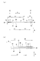
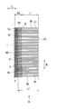
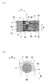
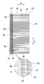
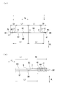
- FIG. 4 is a front plan view of a brush sheet (membrane layer/brush sheet) in which each cushion film layer is formed on each brush surface of the brush sheet in the film layer forming step (ST02) of the brush manufacturing method of the first embodiment.
- 4A is a partially enlarged view of FIG. 4A
- FIG. 4A is an enlarged view taken along arrow C and FIG. 4D
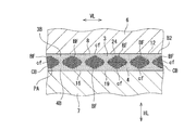
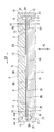
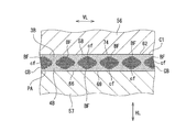
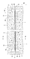
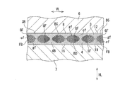
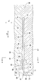
- FIG. 5B is an enlarged sectional view taken along line EE of FIG. 5A.
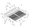
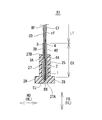
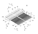
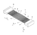
- FIG. 6 is a perspective view of a brush sheet in which each cushion film layer is formed on each brush surface and a base on the brush end side is molded in the molding step (ST04) of the brush manufacturing method of the first embodiment. It is a perspective view showing a brush X1. It is a figure which shows the brush X1 and is sectional drawing of FIG.
- FIG. 12A is an enlarged view seen from an arrow G in FIG. 12A and an enlarged view seen from an arrow H in FIG. 12B
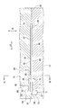
- FIG. 15 is sectional drawing which set the brush sheet (film layer and brush sheet) which formed the cushion film layer on one brush surface in the metal mold
- FIG. 15 is a partially enlarged view of FIG. 14.
- FIG. 16 is an enlarged view taken along the line JJ of FIG. 15.
- FIG. 7 is a perspective view of a brush sheet in which a cushion film layer is formed on one brush surface and a base is formed on each brush end side in the brush manufacturing method of the first embodiment. It is a perspective view showing a brush X2. It is a figure which shows the brush X2, Comprising: It is sectional drawing of FIG. It is a table top view which shows the brush body formed in the brush sheet formation process (ST21) of the manufacturing method of the brush of 2nd Embodiment.
- FIG. 7 is a perspective view of a brush sheet in which a cushion film layer is formed on one brush surface and a base is formed on each brush end side in the brush manufacturing method of the first embodiment. It is a perspective view showing a brush X2. It is a figure which shows the brush X2, Comprising: It is sectional drawing of FIG. It is a table top view which shows the brush body formed in the brush sheet formation process (ST21) of the manufacturing
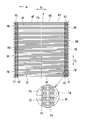
- FIG. 11 is a front plan view of a brush body (membrane layer/brush body) in which each cushion film layer is formed on each brush surface in the film layer forming step (ST22) of the brush manufacturing method of the second embodiment.
- FIG. 22 is an enlarged view of arrow K in FIG. 21.
- 22A is a view taken in the direction of arrow L in FIG. 22, and
- FIG. 23B is an enlarged view taken along the line MM in FIG.
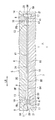
- It is sectional drawing which set the brush body (film layer/brush body) which formed each cushion film layer of each brush surface in the metal mold
- FIG. 25 is an enlarged view taken along line NN in FIG. 24.
- FIG. 26A is a view taken in the direction of arrow O in FIG. 26
- FIG. 27B is an enlarged sectional view taken along the line PP of FIG.
- FIG. 29 is an enlarged view of a QQ section of FIG. 28.
- FIG. 33 is a partially enlarged view of FIG. 32. It is a bb sectional enlarged view of FIG. It is a perspective view of the composite brush sheet which formed the base on each of the brush end sides in the forming step (ST34) of the brush manufacturing method of the third embodiment.
- 36A is a perspective view of the brush X3, and FIG.
- FIG. 36B is a partially enlarged perspective view of FIG. It is a figure which shows the brush X3, Comprising: It is sectional drawing of FIG.36(a). It is a front view which shows the composite brush body formed in the composite brush body formation process (ST41) of the manufacturing method of the brush of 4th Embodiment. It is sectional drawing which set the composite brush body to the metal mold
- FIG. 40 is a sectional view taken along line cc of FIG. 39.
- FIG. 41A is a view taken in the direction of arrow d in FIG. 41
- FIG. 42B is a partially enlarged view of FIG. 42A
- 42A is an enlarged view seen from an arrow e in FIG. 42A and an enlarged view seen from an arrow f in FIG. 42B
- FIG. 43B is an enlarged view taken along line gg in FIG. 43A.
- FIG. 16 is a perspective view of a composite brush sheet in which each cushion film layer is formed on each brush surface and a base is formed on each brush end side in the forming step (ST54) of the brush manufacturing method of the fifth embodiment.
- .. 48A is a perspective view of the brush X4, and FIG. 48B is a partially enlarged perspective view of FIG. 48A.
- FIG. 48 It is a figure which shows the brush X4 and is sectional drawing of FIG. 48 (a).
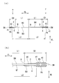
- (a) is a side view showing a composite brush sheet (film layer/composite brush sheet) having a cushion film layer formed on one brush surface
- FIG. 50B is a partially enlarged view of FIG. 50A is an enlarged view seen from the arrow i and j
- FIG. 50B is an enlarged view taken along the line kk of FIG. 51A.
- FIG. 53 is a partially enlarged cross-sectional view of FIG. 52.
- FIG. 54 is an enlarged cross-sectional view taken along the line ll of FIG. 53.
- FIG. 16 is a perspective view of a composite brush sheet in which a cushion film layer is formed on one brush surface and a base is formed on each brush end side in the forming method (ST54) of the brush manufacturing method of the fifth embodiment.
- .. (A) is a perspective view of the brush X5
- (b) is a partially expanded perspective view of FIG. 56(a). It is a figure which shows the brush X5, Comprising: It is sectional drawing of FIG.
- FIG. 59 is a view on arrow m in FIG. 58.
- 59A is a view taken in the direction of arrow n in FIG. 59, and
- FIG. 60B is an enlarged cross-sectional view taken along line oo of FIG.
- FIG. 60 is sectional drawing which set the composite brush body which formed each cushion film layer on each brush surface in the metal mold
- FIG. 16 is a side view of a composite brush body (membrane layer/composite brush body) in which a cushion film layer is formed on one brush surface in the film layer forming step (ST62) of the brush manufacturing method of the sixth embodiment.
- 63A is a view taken in the direction of arrow q in FIG. 63
- FIG. 64B is an enlarged cross-sectional view taken along line rr of FIG. It is sectional drawing which set the composite brush body which formed the cushion film layer in one brush surface in the metal mold
- FIG. 16 is a side view of a composite brush body (membrane layer/composite brush body) in which a cushion film layer is formed on one brush surface in the film layer forming step (ST62) of the brush manufacturing method of the sixth embodiment.
- 63A is a view taken in the direction of arrow q in FIG. 63
- FIG. 64B is an
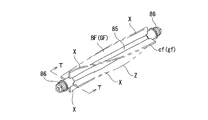
- FIG. 66 is an enlarged view taken along line ss of FIG. 65. It is a perspective view which shows a cleaner. It is a perspective view showing a rotary cleaning tool (brush, rotary shaft, gear shaft).
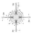
- FIG. 69 is a TT sectional view of FIG. 68. It is a schematic sectional drawing which shows the suction tool (head) of a vacuum cleaner.
- a method of manufacturing a brush according to the present invention will be described with reference to FIGS. 1 to 70. Hereinafter, a method of manufacturing the brush according to the first to sixth embodiments will be described.
- the brush manufacturing method according to the first embodiment includes a brush sheet forming step (ST01), a film layer forming step (ST02), a die setting step (ST03), and a base molding step (ST03). ST04) and a cutting step (ST05).
- the brush manufacturing method of the first embodiment includes a brush sheet forming step (ST01), a film layer forming step (ST01), a mold setting step (ST03), a base forming step (ST04), and a cutting step (ST05).
- the brushes X1 are manufactured by sequentially performing the steps.
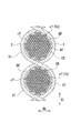
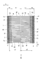
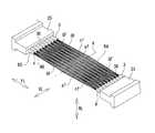
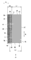
- ⁇ Brush sheet forming step (ST01)> In the brush sheet forming step (ST01), as shown in FIGS. 1 and 2, a brush sheet B1 (brush sheet member) in which a plurality of brush bristles BF made of weft HT are arranged in parallel is formed.
- the weft HT is composed of a carbon fiber bundle CB (fiber bundle) of a large number of carbon fibers cf, as shown in FIG.
- the carbon fiber cf is a PAN-based carbon fiber or a pitch-based carbon fiber, and is a long fiber (filament) having a fiber diameter fd.
- the PAN-based carbon fiber is used (hereinafter the same).
- the PAN-based carbon fiber is formed by firing an acrylic fiber at a high temperature and regularly arranging carbon molecules in a plurality of layers.
- the brush sheet B1 is formed by knitting various fibers with a warp knitting machine (not shown) such as a Russell knitting machine or a tricot knitting machine.
- the warp knitting machine inserts a weft HT made of a carbon fiber bundle CB (fiber bundle) of carbon fibers cf in a fiber direction FL of the carbon fiber bundle CB. It is folded back in U-shape on both sides and arranged in parallel, and each of the folded portions TU (near each folded portion TU) on both sides in the fiber direction FL is knitted into a warp yarn VT in a fiber orthogonal direction VL orthogonal to the fiber direction FL, Each turn-back portion TU of the HT (near each turn-back portion TU) is connected (restricted) by the warp VT. As shown in FIG. 1 and FIG.
- the warp knitting machine is configured such that each of the folded portions TU of the weft HT (carbon fiber bundle CB) has a plurality of warp textures formed of the warp VT, for example, a plurality of chain knitted portions 1 , 2 to connect (restrict) the folded-back portions TU (near the folded-back portions TU) of the weft HT (carbon fiber bundle CB) by the chain knitted portions 1 and 2.
- the warp knitting machine for example, as shown in FIG. 1, has two rows of chain knitting portions 1 and 2 (in the vicinity of each folding portion TU) on both sides of the carbon fiber bundle CB in the fiber direction FL.
- Each warp yarn VT is formed, and each folded-back portion TU of the weft yarn HT (carbon fiber bundle CB) is connected (restricted) by each chain knitting portion 1, 2.
- Each chain knitted part 2 (inner chain knitted part/inner warp) is adjacent to each chain knitted part 1 (outer chain knitted part/outer side warp) in the fiber direction FL of the carbon fiber bundle CB, and each chain knitted part 1 Is formed inside (between each chain knitting part 1).
- the fiber direction FL of the carbon fiber bundle CB is a weft direction in which the weft yarn HT extends
- the fiber orthogonal direction VL is a warp direction (direction in which the warp yarn VT extends) orthogonal to the weft direction.
- the warp knitting machine repeats folding back of the weft HT and inserting (braiding) into the chain knitted portions 1 and 2 (warp yarn VT/warp yarn structure) of each folded portion TU, A belt-shaped brush sheet B1 (brush sheet member) is formed.
- a brush sheet B1 in which a plurality of brush bristles BF made of the weft HT are arranged in parallel in the fiber orthogonal direction VL is formed.
- the brush bristles BF are formed between the chain knitting portions 2 (between the inner chain knitting portions) in the fiber direction FL of the carbon fiber bundle CB, and are arranged in parallel to the fiber orthogonal direction VL. Formed.
- the warp yarn VT may be woven into each of the folded portions TU on both sides of the weft yarn VT (carbon fiber bundle CB) to form the brush sheet B1 (plain weave brush sheet).
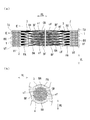
- ⁇ Film layer forming step (ST02)> In the film layer forming step (ST02), as shown in FIGS. 3 to 5, the soft resin PA is applied to the brush sheet B1 to form the cushion film layers 3 and 4 on the brush sheet B1.
- Soft resin PA means a flexible and elastic material, such as soft polyurethane resin, silicone resin, soft polyvinyl chloride resin, soft polyethylene resin, polyamide resin (nylon resin), soft epoxy resin, etc.
- the film layer forming step (ST02) As shown in FIGS. 3 to 5, between the chain knitted portions 2 (each inner chain knitted portion 2/each inner warp VT), the fiber direction FL of the carbon fiber bundle CB and A soft resin PA (soft polyurethane resin) is applied to one brush surface BA (brush surface) and the other brush surface BB (brush back surface) of the brush sheet B1 from the brush thickness direction HL of the brush sheet B1 orthogonal to the fiber orthogonal direction VL. Apply.
- a soft resin PA soft polyurethane resin
- the cushion film layers 3 and 4 are formed on the one brush surface BA and the other brush surface BB of each chain knitted part 2 (each inner chain knitted part 2/each warp VT) side.
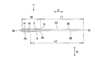
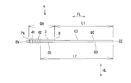
- each of the cushion film layers 3 and 4 includes a brush sheet from a brush center A (brush center position) of each brush bristle BF (brush sheet B1) in the fiber direction FL of the carbon fiber bundle CB.
- a film layer starting point B film layer starting point position separating the brush length L1 on one and the other brush ends BX and BY sides of B1 and a film layer width CH between the brush ends BX and BY of the brush sheet B1 are provided. Is formed.
- the brush length L1 is a brush distance between the brush center A and each chain knitted part 2 (each inner chain knitted part 2/each warp VT) in the fiber direction FL of the carbon fiber bundle CB.
- each film layer starting point B of each cushion film layer 3, 4 is, as shown in FIGS. 3 to 5, each chain knitted part 2 (each inner chain knitted part 2) in the fiber direction FL of the carbon fiber bundle CB.
- /Cushion membrane layers 3 and 4 are formed inside the warp yarns VT (between the chain stitch portions 2), and the cushion film layers 3 and 4 are formed inside the chain stitch portions 2 (between the chain stitch portions 2). To be done.
- the cushion film layers 3 and 4 are, for example, as shown in FIGS. 3 to 5, the starting points of the film layers inside the chain knitted portions 2 (between the chain knitted portions 2).
- B and each chain knitted part 1 are formed with a film layer width CH.
- each of the cushion film layers 3 and 4 has a film layer width CH and is formed to extend in the fiber orthogonal direction VL.
- the soft resin PA moves from one and the other brush surfaces BA, BB of the brush sheet B1 to the brush bristles BF in the fiber orthogonal direction VL. It is applied between the brush bristles BF to continuously form the cushion film layers 3 and 4 in the fiber orthogonal direction VL.
- the soft resin PA is applied to the brush bristles BF of the brush surfaces BA and BB of the brush sheet B1 with the same or substantially the same thickness.
- the soft resin PA is, as shown in FIG. 5B, the carbon fibers of the carbon fiber bundle CB (weft HT) from one and the other brush surfaces BA and BB of the brush sheet B1. It is permeated (impregnated) between cf to cover each carbon fiber cf of the carbon fiber bundle CB.
- a soft resin PA water-soluble soft polyurethane resin
- soft resin PA water-soluble soft polyurethane resin
- Polyurethane resin is dried (cured) to integrally bond the soft resin PA (soft polyurethane resin) and the carbon fibers cf of the carbon fiber bundle CB.
- the soft resin PA is applied between the brush center A and each film layer starting point B in the fiber direction FL of the carbon fiber bundle CB. Not applied brush bristle area (brush bristle BF of brush length L1/carbon fiber cf) and application area (each cushion film layer 3, 4) in which soft resin PA is applied between each film layer start point B and each chain knitted portion 1 To form.
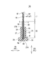
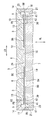
- the mold 5 is composed of an upper mold 6 and a lower mold 7, as shown in FIGS.
- the upper mold 6 and the lower mold 7 are formed in a block body as shown in FIGS. 6 and 7.
- the upper mold 6 has a brush sandwiching recess 8, a plurality (a pair) of molding recesses 9, and a plurality (a pair) of resin injection holes 10.
- the brush sandwiching recess 8 is formed at the center of the upper mold 6 in the width direction LR (left-right direction).
- the brush sandwiching recess 8 is recessed in a rectangular shape from the lower surface 11 of the upper mold 6 and is opened in the lower surface 11.
- the brush pinching recess 8 has a rectangular upper bottom plane 12.
- each molding recess 9 is formed on each side of the brush sandwiching recess 8 in the width direction LR (left-right direction) of the upper mold 6.
- Each molding recess 9 is formed continuously with the brush sandwiching recess 8 and has a main body molding recess 13 and a collar molding recess 14.
- the main body molding recess 13 is formed continuously on both sides of the brush sandwiching recess 8, as shown in FIGS. 6 and 7.
- the main body molding recess 13 is recessed from the upper bottom plane 12 of the brush holding recess 8 and is opened to the lower surface 11 of the upper mold 6 and the upper bottom plane 12 of the brush holding recess 8.
- the collar molding recess 14 is formed continuously with the main-body molding recess 13 in the width direction LR (left-right direction) of the upper mold 6.
- each molding recess 9 the collar molding recess 14 is recessed from the main body molding recess 13 and is opened in the lower surface 11 of the upper mold 6 and the main body molding recess 13.
- Each resin injection hole 10 is formed in the upper mold 6, as shown in FIGS. 6 and 7.
- Each resin injection hole 10 is opened in the main body molding recess 13 of each molding recess 9.
- the lower mold 7 has a brush sandwiching recess 16 and a plurality (a pair) of molding recesses 17.
- the brush sandwiching recess 16 is formed at the center of the lower mold 7 in the width direction LR (left-right direction).
- the brush pinching recess 16 is recessed in a rectangular shape from the upper surface 18 of the lower mold 7 and is opened in the upper surface 18.
- the brush pinching recess 16 has a rectangular lower base plane 19.
- each molding recess 17 is formed on each side of the brush sandwiching recess 16 in the width direction LR (left-right direction) of the lower mold 7.
- Each molding recess 17 is formed continuously with the brush sandwiching recess 16 and has a main body molding recess 20 and a collar molding recess 21.
- the main body molding recess 20 is formed continuously on both sides of the brush sandwiching recess 16, as shown in FIGS. 6 and 7.
- the main body molding recess 20 is recessed from the lower bottom flat surface 19 of the brush holding recess 16 and is opened to the upper surface 18 of the lower mold 7 and the lower bottom flat surface 19 of the brush holding recess 16.
- the collar molding recess 21 is formed continuously with the main body molding recess 20 in the width direction LR (left-right direction) of the lower mold 7, as shown in FIGS. 6 and 7.
- the collar forming recess 21 is recessed from the main body forming recess 20 and is opened in the upper surface 18 of the lower mold 7 and the main body forming recess 20.
- the brush sheet B1 (hereinafter, referred to as "membrane layer/brush sheet B2") on which the cushion film layers 3 and 4 are formed is, as shown in FIGS.
- the membrane layer/brush sheet B2 includes membrane layers 3A on the side of each chain knitting portion 2 (each side of the inner chain knitting portion 2/each warp VT side) of each cushion film layer 3, 4.
- the membrane layer/brush sheet B2 is formed into the respective molding concave portions by forming the respective membrane layer portions 3A and 4A (each cushion membrane layer 3 and 4) including the respective brush ends BX and BY and the chain knit portions 1 and 2.
- the remaining film layer portions 3B and 4B except the film layer portions 3A and 4A are arranged to face the locations 9 and 16 and face the brush sandwiching recesses 8 and 16, respectively.
- the film layer portions 3B and 4B of the film layer/brush sheet B2 are arranged so as to face the upper bottom plane 12 and the lower bottom plane 19.
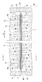
- the upper mold 6 and the lower mold 7 are closed, and the upper mold 6 and the lower mold 7 are pressed against the membrane layer/brush sheet B2.
- the membrane layer/brush sheet B2 is sandwiched.
- the mold setting step (ST03) as shown in FIGS. 6 to 8, between the chain knitting portions 2 (each warp yarn VT), from the brush thickness direction HL of the film layer/brush sheet B2 to each cushion film.
- the upper mold 6 and the lower mold 6 are attached to the remaining film layer portions 3B and 4B except the film layer portions 3A and 3B on the side of the chain knitted portion 2 (on the side of the inner chain knitted portion 2/on the side of each warp VT) in layers 3 and 4.
- the mold 7 is pressed to set the membrane layer/brush sheet B2 in the mold 5.
- the upper bottom flat surface 12 of the brush sandwiching recess 8 is in surface contact with each film layer portion 3B from the brush thickness direction HL of the film layer/brush sheet B2 as shown in FIGS. 7 and 8. And then pressed.
- the lower bottom flat surface 19 of the brush sandwiching recess 16 is in surface contact with each film layer portion 4B from the brush thickness direction HL of the film layer/brush sheet B2, as shown in FIGS. 7 and 8. Be pressed against.
- the upper bottom plane 12 and the lower bottom plane 19 are, as shown in FIG.
- the fibers cf are pressed in liquid-tight contact with the membrane layers 3B, 4B over the fiber orthogonal direction VL while covering the fibers cf and deforming the membrane layers 3B, 4B located between all the brush bristles BF. ..
- the pressing force of the upper mold 6 and the lower mold 7 is absorbed by the deformation of the cushion film layers 3 and 4 (the film layer portions 3B and 4B).
- the upper bottom plane 12 and the lower bottom plane 19 are formed on the respective film layer portions 3B, 4B while deforming the respective film layer portions 3B, 4B of the cushion film layers 3, 4. It is pressed in surface contact. Accordingly, the pressing force of the upper mold 6 and the lower mold 7 can be prevented from acting as a concentrated load on each carbon fiber cf of each brush bristle BF (carbon fiber bundle CB), and each carbon of each brush bristle BF can be prevented.
- the fibers cf are not broken or broken by pressing the upper mold 6 and the lower mold 7 and are not damaged.
- the upper mold 6 and the lower mold 7 press the cushion film layers 3 and 4 while contacting the lower surface 11 and the upper surface 18, as shown in FIGS. To be closed.
- each molding space 23 is a space for molding the base 25 (see FIGS. 10 and 11) of the brush X1.
- each brush space 24 When the upper mold 6 and the lower mold 7 are closed, the brush sandwiching recesses 8 and 16 form the brush spaces 24 as shown in FIG. 7.
- the upper bottom plane 12 of the upper mold 6 and the lower bottom plane 19 of the lower mold 7 are brought into surface contact with the respective film layer portions 3B and 4B (a part of the cushion film layers 3 and 4). By pressing, each molding space 23 is liquid-tightly sealed.
- each of the film layer portions 3A and 4A (a part of each of the cushion film layers 3 and 4) is moved from the brush space 24 into each molding space 23 in the fiber direction FL of the carbon fiber bundle CB. It projects and is arranged in each molding space 23.
- the protrusion amount of each film layer portion 3A and 4A is 0.5 mm or more.
- the amount of protrusion of each of the membrane layer portions 3A and 4A is the length of protrusion from the brush space 24 into each of the molding spaces 23 in the fiber direction FL of the carbon fiber bundle CB (the same applies hereinafter).
- the cushion film layers 3 and 4 are continuously arranged in the brush space 24 and the molding spaces 23 in the fiber direction FL of the carbon fiber bundle CB, as shown in FIG. 7.
- ⁇ Base forming process (ST04)> In the base forming step (ST04), as shown in FIGS. 6 and 7, the brushes of the film layer/brush sheet B2 are pressed from the remaining film layer portions 3B and 4B on which the upper mold 6 and the lower mold 7 are pressed. The ends 3X and 3Y are filled with the synthetic resin PB, and the bases 25 are formed on the brush ends BX and BY of the membrane layer/brush sheet B2, respectively.
- the synthetic resin PB is filled into the molding spaces 23 from the resin injection holes 10.
- the synthetic resin PB is, as shown in FIGS. 6 and 7, the brush ends BX and BY of the film layer/brush sheet B2, the chain knitting portions 1 and 2 (each warp yarn VT). ), and each film layer part 3A, 4A (a part of each cushion film layer 3, 4), and it is filled in each molding space 23.
- the synthetic resin PB filled in each molding space 23 is dammed by the respective film layer portions 3B and 4B which are deformed by being in surface contact with the upper bottom plane 12 and the lower bottom plane 19.
- the synthetic resin PB can be prevented from flowing into the brush space 24 and entering the carbon fibers cf of the brush bristles BF (carbon fiber bundles CB), and the flexibility of the brush bristles can be secured to ensure that the brushes are not brushed. It can exert the function of hair.
- the base molding step (ST04) when each molding space 23 is filled with the synthetic resin PB, the mold 5 (the upper mold 6 and the lower mold 7) is cooled and the synthetic resin PB is cured to form a film.
- the base 25 is fixed (fixed) to each of the brush ends BX and BY of the layer/brush sheet B1.
- the synthetic resin PB filled in each molding space 23 is cured, the upper mold 6 and the lower mold 7 are opened, and the membrane layer/brush sheet B1 on which each base 25 is molded is formed. Remove from mold 5.
- ⁇ Cutting process (ST05)> In the cutting step (ST05), as shown in FIGS. 9 and 10, the brush sheet B1 is placed between the cushion membrane layers 3 and 4 formed by forming the bases 25 on the membrane layer/brush sheet B2 in the fiber orthogonal direction VL. Disconnect.
- the membrane layer/brush sheet B2 on which the bases 25 are formed has fiber crossing at the brush center A of the brush sheet B1 between the cushion membrane layers 3 and 4, as shown in FIG. It is cut in the direction VL. All the brush bristles BF of the brush sheet B1 are cut in the fiber orthogonal direction VL at the brush center A of the brush sheet B1. As a result, in the cutting step (ST05), the brush sheet B1 is cut to be divided into a plurality (a pair) of brushes X1, as shown in FIGS. 10 and 11.
- the brush X1 includes a base 25 and a brush body C1.
- the base 25 has a base body 27 and a plurality (one pair) of collar portions 28.
- the base body 27 is formed in a rectangular parallelepiped having a rectangular cross section.
- Each flange 28 is formed in a rectangular parallelepiped having a rectangular cross section.
- Each collar 28 is formed integrally with the base body 27.
- Each of the collar portions 28 is located on one table end 27A side of the table body 27 in the table height direction FD (fiber direction FL) of the base 25, and in the table width direction HD orthogonal to the table height direction FD, It is formed so as to project from the base body 27.
- the brush body C1 includes a plurality of brush bristles BF, a plurality (a pair) of chain knitted portions 1 and 2 (each warp VT), and a plurality (a pair) of cushion film layers 3 and 4.
- Each of the brush bristles BF is formed by juxtaposing a large number of carbon fiber bundles CB of carbon fibers cf folded back in a U shape in a fiber orthogonal direction VL orthogonal to the fiber direction FL.
- the chain knitted portion 1 (warp yarn VT) extends in the fiber orthogonal direction VL.
- the chain knitted portion 1 restrains the folded-back portion TU (near the folded-back portion TU) of each brush bristle BF (carbon fiber bundle CB) to connect each brush bristle BF.
- the chain knitted portion 2 (warp yarn VT) extends in the fiber orthogonal direction VL.
- the chain stitch portion 2 is located between the other brush end CX (brush tip) of the brush body C1 and the chain stitch portion 1, and is disposed adjacent to the chain stitch portion 1.
- the chain knitted portion 2 restrains the brush bristles BF (carbon fiber bundle CB) and connects the brush bristles BF.
- the cushion film layer 3 is one brush surface BA (brush surface) of the brush body C1 from the brush thickness direction HL of the brush body C1 orthogonal to the fiber direction FL and the fiber orthogonal direction VL. Is formed.
- the cushion film layer 4 is formed on the other brush surface BB (back surface of the brush) of the brush body C1 in the brush thickness direction HL.
- the cushion film layers 3 and 4 are made of a soft resin PA (soft polyurethane resin).
- each of the cushion film layers 3 and 4 is brushed from the other brush end CX (brush tip) of the brush body C1 to the one brush end BX side of the brush body C1 in the fiber direction FL.
- a film layer width CH is formed between the film layer starting point B (film layer starting point position) separating the length L1 and one brush end BX of the brush body C1.
- each of the cushion film layers 3 and 4 has, for example, a film layer starting point B on the brush end CX side (between the chain knitting part 2 and the brush tip CX) of the chain knitting part 2 and the chain knitting part 1. Is formed with a film layer width CH between them.
- each of the cushion film layers 3 and 4 has a film layer width CH and is formed to extend in the fiber orthogonal direction.
- the cushion film layers 3 and 4 are arranged (formed) between the brush surfaces BA and BB of the brush body C1 and the carbon fibers Cf of the brush bristles BF (carbon fiber bundle CB), respectively. Cover each carbon fiber cf. As shown in FIG. 10, the cushion film layers 3 and 4 are continuously formed (arranged) in the fiber orthogonal direction VL across the brush surfaces BA and BB of the brush body C1 and between the brush bristles BF. ..
- the brush bristles BF carbon fiber bundles CB
- the brush body C1 is embedded in the base 25 from one brush end BX and is fixed to the base 25.
- the respective film layer portions 3A and 4A on the side of the chain knitted portion 2 (the warp VT) of the respective cushion film layers 3 and 4 are embedded in the base 25, and the rest except the respective film layer portions 3A and 4A.
- the film layer portions 3B and 4B of the above are projected from the other base end 27B of the base body 27 and fixed to the base 25.
- the film layer portions 3A and 4A are covered with a base 25 (synthetic resin PB) and integrally fixed to the base 25, as shown in FIG.
- the brush X1 includes one brush end BX of the brush body C1, each chain knitted part 1 and 2 (each warp VT) and each film layer part 3A and 4A (a part of each cushion film layer 3 and 4). It is embedded in the base 25 and one brush end CX side (brush tip side) of the brush body C1 and each film layer part 3B, 4B from the other base end 27B (base end of the base 25) of the stand body 27. It is formed to project.
- the brush X1 protects the carbon fibers cf of the brush bristles BF (carbon fiber bundle CB) with the cushion film layers 3 and 4 of the soft resin PA.
- the cushion film layers 3 and 4 (soft resin PA) are continuously arranged inside the base 25 and outside the base 25 with the base end 27B of the base 25 (base main body 27) as a boundary. There is.
- each brush bristle FB (each carbon fiber cf) is bent in multiple directions (fiber orthogonal direction VL, brush thickness direction HL)
- the force due to the bending is applied to each cushion film layer 3, 4
- each carbon fiber cf of each brush bristle BF should be broken and broken from the base end 27B of the base 25 (base body 27) as a starting point (base point). Is suppressed (reduced).
- the cushion film layer is formed on one brush surface BA (or the brush surface BB) of the brush surfaces BA, BB on both sides of the brush sheet B1. 3 (or the cushion film layer 4) may be formed to manufacture the brush X2 (see FIGS. 18 and 19), which will be described below.
- the same reference numerals as those in FIGS. 1 to 11 denote the same members and the same configurations, and thus detailed description thereof will be omitted.
- ⁇ Film layer forming step (ST02)> In the film layer forming step (ST02), as shown in FIGS. 12 and 13, the soft resin PA is applied to the brush sheet B1 to form the cushion film layer 3 (or the cushion film layer 4) on the brush sheet B1.
- the film layer forming step (ST02) As described with reference to FIGS. 3 to 5, between the chain knitting portions 2 (each warp yarn VT), one of the brush sheets B1 from the brush thickness direction HL of the brush sheet B1.
- the soft resin PA soft polyurethane resin
- the soft resin PA soft polyurethane resin
- the cushion film layer 3 is formed on the one brush surface BA on the side of each chain knitted part 2 (each inner chain knitted part 2/warp VT) by covering with the soft resin PA.
- the cushion film layer 3 has, for example, the film layer starting point B inside the chain knitted portions 2 (between the chain knitted portions 2), as described in FIGS. 3 to 5. , And each chain knitted part 1 (each outer chain knitted part 1/each warp VT) having a film layer width CH (see FIGS. 12 and 13).
- the soft resin PA is, in the fiber orthogonal direction VL, from the one brush surface BA of the brush sheet B1 to each of the brush bristles BF and each of the brushes, as described with reference to FIGS. 3 to 5. It is applied between the bristles BF to continuously form the cushion film layer 3 in the fiber orthogonal direction VL.
- the soft resin PA is applied on one brush surface BA of the brush sheet B1 with the same or substantially the same thickness.
- the soft resin PA permeates (impregnates) between the carbon fibers cf of the carbon fiber bundle CB (weft VT) from one brush surface BA of the brush sheet B1 as shown in FIG. 13(b). 3) and covers each carbon fiber cf of the carbon fiber bundle CB.
- the soft resin PA is applied between the brush center A and each film layer start point B in the fiber direction FL of the carbon fiber bundle CB.
- An application area (cushion film layer 3) in which the soft resin PA is applied is formed between the non-brush bristle area and each film layer starting point B and each chain knitted portion 1.
- the brush sheet B1 on which the cushion film layer 3 is formed (hereinafter, referred to as “membrane layer/brush sheet B3”) has one brush surface BA and one brush surface BA as shown in FIGS.
- Each cushion film layer 3 is directed toward the brush nipping recess 8 and each molding recess 9 of the upper mold 6, and the other brush surface BB is directed to each brush nipping recess 16 of the lower mold 7 and each molding recess 17 thereof. It is arranged between the upper mold 6 and the lower mold 7. As shown in FIG.
- the membrane layer/brush sheet B3 has a cavity for forming the membrane layer portion 3A on each side of the chain knitting portion 2 (each side chain knitting portion 2 side/each warp VT side) of the cushion membrane layer 3 in each molding recess. 9 and 17, and the remaining film layer portion 3B excluding each film layer portion 3A is located in the brush sandwiching recesses 8 and 16, and is disposed between the upper mold 6 and the lower mold 7.
- the membrane layer/brush sheet B3 faces the molding recesses 9 and 16 with the membrane layer portion 3A (a part of the cushion membrane layer 3) including the brush ends BX and BY and the chain knit portions 1 and 2, respectively.
- the remaining film layer portion 3B except the film layer portion 3A is arranged so as to face the brush sandwiching recesses 8 and 16.
- the film layer portion 3B of the film layer/brush sheet B3 is arranged so as to face the upper bottom plane 12 of each brush sandwiching recess 8.
- the upper mold 6 and the lower mold 7 are closed, and the upper mold 6 and the lower mold 7 are pressed against the membrane layer/brush sheet B3.
- the membrane layer/brush sheet B2 is sandwiched.
- the mold setting step (ST03) as shown in FIG. 14 to FIG. 16, from the brush thickness direction HL of the film layer/brush sheet B3, each chain knitted part 2 side (each inner chain knitted part) in the cushion film layer 3 is The upper die 6 is pressed against the remaining film layer portion 3B except the film layer portion 3A (2 side/each warp VT side).
- the mold setting step (ST03) as shown in FIGS.
- the film layer/brush between each chain knitting part 2 (each warp yarn VT) from the brush thickness direction HL of the film layer/brush sheet B3.
- the lower die 7 is pressed against the other brush surface BB of the sheet B3 to set the membrane layer/brush sheet B3 in the die 5.
- the upper bottom flat surface 12 of the brush sandwiching recess 8 is pressed in surface contact with each film layer portion 3B from the brush thickness direction HL of the film layer/brush sheet B3 as shown in FIG. ..
- the lower bottom flat surface 19 of the brush sandwiching recess 16 is pressed against the other brush surface BB (back surface of the brush) from the brush thickness direction HL of the film layer/brush sheet B3, as shown in FIG. ..
- the upper bottom plane 12 and the lower bottom plane 19 cover each carbon fiber cf of a part of all the brush bristles BF, and all the brush bristles BF. While deforming the membrane layer portion 3B located between the BFs, the membrane layer portion 3B and the other brush surface BB are surface-contacted and pressed in the fiber orthogonal direction VL.
- the pressing force of the upper mold 6 and the lower mold 7 is absorbed by the deformation of each cushion film layer 3 (each film layer portion 3B).
- the upper bottom plane 12 and the lower bottom plane 19 deform each film layer portion 3B of each cushion film layer 3 and also each film layer portion 3B and the other brush surface BB (brush surface). It is pressed in contact with the back side). Accordingly, the pressing force of the upper mold 6 and the lower mold 7 can be prevented from acting as a concentrated load on each carbon fiber cf of each brush bristle BF (carbon fiber bundle CB), and each carbon of each brush bristle BF can be prevented.
- the fibers cf are less susceptible to damage such as breaking and breaking due to the pressing force of the upper mold 6 and the lower mold 7.
- the upper mold 6 and the lower mold 7 press the cushion film layer 3 and the other brush surface BB while pressing the lower surface 11 and the upper surface 18 as shown in FIGS. 14 and 16. Is abutted and closed.
- each membrane layer portion 3A (a part of each cushion membrane layer 3) protrudes from the brush space 24 into each molding space 23 in the fiber direction FL of the carbon fiber bundle CB, as shown in FIG. It is arranged in the molding space 23.
- the cushion film layer 3 is continuously arranged in the brush space 24 and each molding space 23, as shown in FIG.
- ⁇ Base forming process (ST04)> In the base forming step (ST04), as shown in FIGS. 14 and 15, the remaining film layer portion 3B on which the upper mold 6 and the lower mold 7 are pressed, and the film layer/brush sheet B2 from the other brush surface BB.
- the synthetic resin PB is filled into the brush ends 3X and 3Y of the above, and the base 25 is formed on each of the brush ends BX and BY of the membrane layer/brush sheet B2.
- each molding space 23 from each resin injection hole 10.
- the synthetic resin PB is, as shown in FIGS. 14 and 15, each brush end BX, BY of the film layer/brush sheet B2, each chain knitted part 1 and 2, the film layer part 3A.
- the molding space 23 is filled with (a part of the cushion film layer 3) and a part of the brush surface BB.
- the base molding step (ST04) after curing the synthetic resin PB, the upper mold 6 and the lower mold 7 are opened, and the film layer/brush sheet B3 on which each base 25 is molded is taken out of the mold 5.
- ⁇ Cutting process (ST05)> In the cutting step (ST05), as shown in FIGS. 17 and 18, the brush sheet B1 is cut in the fiber orthogonal direction VL between the cushion membrane layers 3 formed by forming the bases 25 on the membrane layer/brush sheet B3. To do.
- the membrane layer/brush sheet B3 on which the bases 25 are formed is, as shown in FIG. 17, at the brush center A of the brush sheet B1 between the cushion membrane layers 3, the fiber orthogonal direction VL. To be disconnected. All the brush bristles FG of the brush sheet B1 are cut in the fiber orthogonal direction VL at the brush center A of the brush sheet B1. As a result, in the cutting step (ST05), the brush sheet B1 is cut to be divided into a plurality (a pair) of brushes X2, as shown in FIGS. 18 and 19.
- the brush X2 includes a base 25 and a brush body C2 (membrane layer/brush body C2).
- the base 25 has a base body 27 and a plurality of (a pair of) flanges 28, as described with reference to FIGS. 10 and 11.
- the brush body C2 has a plurality of brush bristles BF, a plurality (a pair) of chain knitted portions 1 and 2 (each warp YT), and a cushion film layer 3 as in the case described with reference to FIGS. 10 and 11 (FIG. 18). And FIG. 19).
- the cushion film layer 3 is formed on one brush surface BA (brush surface) of the brush body C2 from the brush thickness direction HL of the brush body C2.
- the cushion film layer 3 includes a film start point B that separates the brush length L1 from the other brush end CY (brush tip) of the brush body C2 to one brush end BX of the brush body C2, and the brush body C2.
- the brush body C2 in the fiber direction FL of the carbon fiber bundle CB, the brush region (brush length L1) in which the cushion film layer 3 is not formed between the other brush end CY (brush tip) and the film layer start point B.
- the area (cushion area) of the cushion film layer 3 is formed between the brush bristles BF/carbon fiber cf), the film layer starting point B, and the chain knit portion 1.
- the brush bristles BF carbon fiber bundles CB
- the brush body C2 is embedded in the base 25 from one brush end BX and is fixed to the base 25.
- the film layer portion 3A on the chain knitting portion 2 side of the cushion film layer 3 is embedded in the base 25, and the remaining film layer portion 3B excluding the film layer portion 3A is provided on the other base end 27B of the base body 27. It projects from and is fixed to the base 25.
- the brush X2 has one brush end BX of the brush body C2, each chain knitted portion 1, 3 and the film layer portion 3A (a part of the cushion film layer 3) embedded in the base 25, and the brush body
- the other brush end CX side of C2 (brush tip side) and the film layer portion 3B are formed to project from the other stand end 27B of the stand body 27 (stand end of the base 25).
- the brush X2 protects the carbon fibers cf of the brush bristles BF (carbon fiber bundle CB) by covering them with the cushion film layer 3 of the soft resin PA.
- the cushion film layer 3 soft resin PA
- the cushion film layer 3 soft resin PA
- the brush X2 even if each of the brush bristles BF (each of the carbon fibers cf) is bent in multiple directions (the fiber orthogonal direction VL and the brush thickness direction HL), the bending force causes the cushion film layer 3 (soft resin).
- each carbon fiber cf of each brush bristles BF is suppressed from being broken and broken from the base end 27B of the base 25 (base main body 27) as a starting point (base point) ( Will be reduced).
- the brush manufacturing method of the second embodiment includes a brush body forming step (ST21), a film layer forming step (ST22), a mold setting step (ST23), and a base molding step (ST23). ST24).
- the brush manufacturing method of the second embodiment is carried out in the order of a brush body forming step (ST21), a film layer forming step (ST22), a mold setting step (ST23), and a base molding step (ST24), and a brush is formed.
- X1 (see FIGS. 10 and 11) is manufactured.
- ⁇ Brush body forming step (ST21)> In the brush body forming step (ST21), as shown in FIG. 20, a plurality of brush bristles BF composed of a carbon fiber bundle FB of a large number of carbon fibers cf are arranged in a fiber orthogonal direction VL orthogonal to the fiber direction FL of the carbon fiber bundle FB. In parallel, the brush body C1 is formed.
- the carbon fiber bundle CB (weft VS) is cut at the brush center A of the brush sheet B1 to form the brush body C1.
- the brush body C1 is composed of a plurality of brush bristles BF on one side, which are obtained by cutting the brush sheet B1 in the fiber orthogonal direction VL at the brush center A of the brush sheet B1, and chain knitted portions 1 and 2 (see FIG. 20). ).
- the brush body C1 has a plurality of brush bristles BF and a plurality (a pair) of chain knitted portions 1 and 2 (each warp VS), as shown in FIG. As shown in FIG.
- each of the brush bristles BF is formed by arranging a large number of carbon fiber bundles CB of carbon fibers cf folded back in a U shape in the fiber orthogonal direction VL orthogonal to the fiber direction FL.
- the chain knitted portions 1 and 2 connect (restrict) the folded portions TU (near the folded portions TU) of the brush body C1.
- each of the brush bristles BF is formed between the other brush end CX (brush tip) of the brush body C1 and the chain knitting portion 2 in the fiber direction FL of the carbon fiber bundle, and is in the fiber orthogonal direction. It is formed in parallel with VL.
- a plurality of warp yarns VT are laid in parallel in the fiber direction FL (weft direction) of the carbon fiber bundle CB and woven into each brush bristles BF.
- ⁇ Film layer forming step (ST22)> In the film layer forming step (ST22), as shown in FIGS. 21 to 23, the soft resin PA is applied to the brush body C1 to form the cushion film layers 3 and 4 on the brush body C1.
- the film layer forming step (ST22) As shown in FIG. 21 to FIG. 23, one of the brush body C1 from the brush thickness direction HL of the brush body C1 orthogonal to the fiber direction FL of the carbon fiber bundle CB and the fiber orthogonal direction VL.
- the soft resin PA is applied to the brush surface BA (brush surface) and the other brush surface BB (brush back surface).
- the soft resin PA is applied to each of the brush surfaces BA and BB of the brush body C1, and the carbon fibers cf of the brush bristles BF are covered with the soft resin PA to form the brush body C1.
- the cushion film layers 3 and 4 are formed on one brush surface BA on one brush end BX side (chain knitting portion 2 side/warp yarn VT side) and the other brush surface BB, respectively.
- each of the cushion film layers 3 and 4 has a brush length L1 from the other brush end CX of the brush body C1 to the one brush end BX side in the fiber direction FL of the carbon fiber bundle CB.
- a film layer width CH is formed between the separating film layer starting point B and one brush end BX of the brush body C1.
- the film layer starting point B of each of the cushion film layers 3 and 4 is located inside the chain knitted portion 2 (the warp yarn VT) (located between one brush end CX and the chain knitted portion 2), and the cushion film layer 3 is formed. , 4 are formed inside the chain knitted portion 2.
- each of the cushion film layers 3 and 4 is, for example, as shown in FIGS. 21 to 23, inside the chain stitch portion 2 (between the chain stitch portion 2 and the other brush end CX).
- the film layer width CH is formed between the film layer starting point B and the chain knitted portion 1 (the warp yarn VT).
- each of the cushion film layers 3 and 4 has a film layer width CH and is formed to extend in the fiber orthogonal direction VL.
- the soft resin PA moves from one and the other brush surfaces BA and BB of the brush body C1 to the brush bristles BF and each in the fiber orthogonal direction VL. It is applied between the brush bristles BF to continuously form the cushion film layers 3 and 4 in the fiber orthogonal direction VL.
- the soft resin PA is applied to the brush bristles BF of the brush surfaces BA and BB of the brush body C1 with the same or substantially the same thickness.
- the soft resin PA is, as shown in FIG. 23(b), between the one and the other brush surfaces BA and BB of the brush body C1 and the respective carbon fibers cf of the carbon fiber bundle CB. It is permeated (impregnated) and covers each carbon fiber cf of the carbon fiber bundle CB.
- the soft resin PA water-soluble soft polyurethane resin
- the soft resin PA water-soluble soft polyurethane resin
- (Polyurethane resin) is dried (cured), and the soft resin PA (soft polyurethane resin) and the carbon fibers cf of the carbon fibers CB are integrally bonded.
- the soft resin PA is provided between the other brush end CX and the film layer starting point B in the fiber direction FL of the carbon fiber bundle CB.
- An application area (each cushion film layer 3) in which the soft resin PA is applied between the non-applied brush bristle area (brush bristle BF of the brush length L1/carbon fiber cf) and the membrane layer start point B and the chain knitted portion 1 (warp VT). , 4) is formed.
- the mold 55 is composed of an upper mold 56 and a lower mold 57, as shown in FIGS.
- the upper die 56 and the lower die 57 are formed in a block body as shown in FIG.
- the upper die 56 has a brush sandwiching recess 58, a molding recess 59, and a resin injection hole 60.
- the brush sandwiching recess 58 is formed at the center of the upper mold 56 in the width direction LR (left-right direction).
- the brush sandwiching recess 58 is recessed in a rectangular shape from the lower surface 61 of the upper mold 56 and is opened in the lower surface 61.
- the brush pinching recess 58 has a rectangular upper bottom flat surface 62.
- the molding recess 59 is formed on one end side (left end side) of the brush holding recess 58 in the width direction LR (left-right direction) of the upper mold 56.
- the molding recess 59 is formed continuously with the brush sandwiching recess 58 and has a main body molding recess 63 and a collar molding recess 64.
- the main body molding recess 63 is formed continuously with one end of the brush sandwiching recess 58, as shown in FIG.
- the main body molding recess 63 is recessed from the upper bottom flat surface 62 of the brush holding recess 58, and is opened to the lower surface 61 of the upper mold 56 and the upper bottom flat surface 62 of the brush holding recess 58.
- the collar forming recess 64 is formed continuously with the main body forming recess 63 in the width direction LR (left-right direction) of the upper die 56, as shown in FIG.
- the collar molding recess 64 is recessed from the main body molding recess 63 and opened to the lower surface 61 of the upper die 56 and the main body molding recess 63.
- the resin injection hole 60 is formed in the upper mold 56 as shown in FIG.
- the resin injection hole 60 is opened in the main body forming recess 63 of the forming recess 59.
- the lower die 57 has a brush sandwiching recess 66 and a molding recess 67.
- the brush sandwiching recess 66 is formed at the center of the lower die 57 in the width direction LR (left-right direction).
- the brush sandwiching recess 66 is recessed in a rectangular shape from the upper surface 68 of the lower mold 57 and is opened in the upper surface 68.
- the brush pinching recess 66 has a rectangular lower bottom flat surface 69.
- the molding recess 67 is formed on one end side (left end side) of the brush holding recess 66 in the width direction LR (left-right direction) of the lower mold 57.
- the molding recess 67 is formed continuously with the brush sandwiching recess 66, and has a main body molding recess 70 and a collar molding recess 71.
- the main body forming recess 70 is continuously formed on one end side (left end side) of the brush sandwiching recess 66, as shown in FIG.
- the main body molding recess 70 is recessed from the lower bottom flat surface 69 of the brush holding recess 66, and is opened to the upper surface 68 of the lower mold 57 and the lower bottom flat surface 69 of the brush holding recess 66.
- the collar forming recess 71 is formed continuously with the main body forming recess 70 in the width direction LR (left-right direction) of the lower die 57, as shown in FIG.
- the collar molding recess 71 is recessed from the main body molding recess 70 and is opened to the upper surface 68 of the lower mold 57 and the main body molding recess 70.
- the brush body C1 on which the cushion film layers 3 and 4 are formed (hereinafter, referred to as "membrane layer/brush body C1") is one of the brushes as shown in FIGS. 24 and 25.
- the surface BA and the cushion film layer 3 are directed toward the brush nipping recess 58 and the molding recess 59 of the upper mold 56, and the other brush surface BB and the cushion film layer 4 are directed toward the brush nipping recess 66 and the molding recess of the lower mold 57. It is arranged between the upper die 56 and the lower die 57 toward the place 67. As shown in FIG.
- the membrane layer/brush body C1 includes the respective membrane layer portions 3A and 4A on one brush end BX side (chain knitting portion 2 side/warp yarn VT side) of the cushion membrane layers 3 and 4, respectively.
- the upper die 56 and the lower die are located in the molding recesses 59 and 67, and the remaining film layer portions 3B and 4B except the film layer portions 3A and 4A are located in the brush sandwiching recesses 58 and 66. It is arranged between the molds 57.
- the membrane layer/brush body C1 is provided with one brush end BX and each membrane layer portion 3A, 4A including each chain knitting portion 1, 2 (a part of each cushion membrane layer 3, 4) in each molding recess.
- the film layer portions 3B and 4B of the film layer/brush body C1 are arranged to face the upper bottom plane 62 and the lower bottom plane 69.
- the upper mold 56 and the lower mold 57 are closed and the upper mold 56 and the lower mold 57 are pressed against the membrane layer/brush body C1.
- the upper die 56 and the lower die 57 are pressed against the remaining membrane layer portions 3B and 4B except the respective membrane layer portions 3A and 4A (the portion 2 side/the warp VT side) to form the membrane layer/brush body C1 into the die.
- Set to 55 the remaining membrane layer portions 3B and 4B except the respective membrane layer portions 3A and 4A (the portion 2 side/the warp VT side) to form the membrane layer/brush body C1 into the die.
- the upper bottom flat surface 62 of the brush sandwiching recess 58 is in surface contact with the film layer portion 3B from the brush thickness direction HL of the film layer/brush body C1 as shown in FIGS. 24 and 25. It is pressed.
- the lower bottom flat surface 69 of the brush sandwiching recess 66 is in surface contact with the film layer portion 4B from the brush thickness direction HL of the film layer/brush body C1 as shown in FIGS. 24 and 25. It is pressed.
- the upper bottom plane 62 and the lower bottom plane 69 are, as shown in FIG.
- the pressing force of the upper mold 56 and the lower mold 57 is absorbed by the deformation of the cushion film layers 3 and 4 (the film layer portions 3B and 4B).
- the upper bottom plane 62 and the lower bottom plane 69 are formed on the respective film layer portions 3B and 4B while deforming the respective film layer portions 3B and 4B of the cushion film layers 3 and 4. It is pressed in surface contact.
- the pressing force of the upper mold 56 and the lower mold 57 can be prevented from acting as a concentrated load on each carbon fiber cf of each brush bristle BF (carbon fiber bundle CB), and each carbon of each brush bristle BF can be prevented.
- the fibers cf are not broken or damaged by pressing the upper mold 56 and the lower mold 57.
- the upper mold 56 and the lower mold 57 press the cushion film layers 3 and 4 while contacting the lower surface 61 and the upper surface 68, as shown in FIGS. To be closed.
- the molding space 73 is a space for molding the base 25 (see FIGS. 10 and 11) of the brush X1.
- the brush sandwiching recesses 58, 66 form a brush space 74 as shown in FIG.
- the brush space 74 presses the upper bottom plane 62 of the upper mold 56 and the lower bottom plane 69 of the lower mold 57 into surface contact with each of the film layer portions 3B and 4B (a part of each cushion film layer 3 and 4). By attaching it, it is liquid-tightly sealed from the molding space 73.
- each membrane layer part 3A, 4A protrudes from the brush space 74 into the molding space 73 in the fiber direction FL of the carbon fiber bundle CB, as shown in FIG. And is placed in the molding space 73.
- the cushion film layers 3 and 4 are continuously arranged in the brush space 74 and the molding space 73 in the fiber direction FL of the carbon fiber bundle CB.
- ⁇ Base forming process (ST24)> In the base forming step (ST24), as shown in FIG. 24, one brush end BX of the film layer/brush body C1 is pressed from the remaining film layer portions 3B and 4B on which the upper mold 56 and the lower mold 57 are pressed.
- the side (chain side 2 side/warp VT side) is filled with synthetic resin PB, and the base 25 is formed on one brush end BX side of the membrane layer/brush body C1.
- the molding space 73 is filled with the synthetic resin PB from the resin injection hole 60.
- the synthetic resin PB is, as shown in FIG. 24, one brush end BX of the film layer/brush body C1, each chain knitted part 1 and 2 (each warp yarn VT), and each film.
- the molding space 73 is filled while covering the layer portions 3A and 4A (a part of the cushion film layers 3 and 4).
- the synthetic resin PB filled in the molding space 73 is dammed by the respective film layer portions 3B and 4B which are deformed by being in surface contact with the upper bottom plane 62 and the lower bottom plane 69, and are molded.
- the synthetic resin PB can be prevented from flowing into the brush space 74 and invading the carbon fibers cf of the brush bristles BF (carbon fiber bundle CB), thereby ensuring the flexibility of the brush bristles and ensuring that the brushes It can exert the function of hair.
- the base molding step (ST24) when the molding space 73 is filled with the synthetic resin PB, the mold 55 (the upper mold 56 and the lower mold 57) is cooled, the synthetic resin PB is cured, and the film layer is formed.
- the base 25 is formed on one brush end BX side of the brush body C1.
- the base molding step (ST24) when the synthetic resin PB filled in the molding space 23 is cured, the upper mold 56 and the lower mold 57 are opened to mold the film layer/brush body C1 on which the base 25 is molded into a mold. Take out from 55. As a result, the brush X1 is manufactured (see FIGS. 10 and 11).
- the cushion film layer is formed on one brush surface BA (or the brush surface BB) of the brush surfaces BA and BB on both sides of the brush body C1.
- 3 (cushion film layer 4) may be formed to manufacture the brush X2 (see FIGS. 18 and 19), which will be described below.
- ⁇ Film layer forming step (ST22)> In the film layer forming step (ST22), as shown in FIGS. 26 and 27, the soft resin PA is applied to the brush body C1 to form the cushion film layer 3 (or the cushion film layer 4) on the brush body C1.
- the soft resin PA soft polyurethane resin
- the soft resin PA is applied to the one brush surface BA of the brush body C1 from the brush thickness direction HL in the same manner as described with reference to FIGS. 21 to 23. Apply (see FIGS. 26 and 27).
- the soft resin PA is applied to one brush surface BA of the brush body C1 and the carbon fiber cf of each brush bristle BF is covered with the soft resin PA.
- the cushion film layer 3 is formed on one brush surface BA on one brush end BX side (chain knitting portion 2 side/warp yarn VT side) of the brush body C1.
- the cushion film layer 3 has, for example, the film layer starting point B between the chain stitch portion 2 and the other brush end CX and the chain stitch in the same manner as described in FIGS.
- the film layer CH is formed between the parts 1 (the warp yarns VT) (see FIGS. 26 and 27).
- the soft resin PA is applied between the brush bristles FB and the brush bristles FB from one brush surface BA of the brush body C1 in the same manner as described with reference to FIGS. 21 to 23. Then, the cushion film layer 3 is formed continuously in the fiber orthogonal direction VL. The soft resin PA is applied with the same or substantially the same thickness on one brush surface BA of the brush body C1.
- the soft resin PA is permeated (impregnated) between the carbon fibers cf of the carbon fiber bundle CB from one brush surface BA of the brush body C1, as shown in FIG. 27(b), The carbon fibers cf of the carbon fiber bundle CB are covered.
- the soft resin PA is provided between the other brush end CX and the film layer start point B in the fiber direction FL of the carbon fiber bundle CB.
- An application area (cushion film layer 3) to which the soft resin PA is applied is formed between the brush bristle area which is not applied and the membrane layer starting point B and the chain knitted portion 1 (the warp yarn VT).
- the brush body C1 (hereinafter, referred to as “membrane layer/brush body C2”) on which the cushion film layer 3 is formed, as shown in FIGS.
- the cushion film layer 3 is directed toward the brush nipping recess 58 and the molding recess 59 of the upper mold 56, and the other brush surface BB is directed toward the brush nipping recess 66 and the molding recess 67 of the lower mold 57 to form the upper metal mold. It is arranged between the mold 56 and the lower mold 57. As shown in FIG.
- the membrane layer/brush body C2 is formed by forming the membrane layer portion 3A on one brush end BX side (chain knitting portion 2 side/warp yarn VT side) of the cushion membrane layer 3 into the respective molding recesses 59, 67. And the remaining film layer portion 3B except each film layer portion 3A is located in the brush sandwiching recesses 58 and 66, and is disposed between the upper mold 56 and the lower mold 57. As a result, the membrane layer/brush body C2 forms the membrane layer portion 3A (a part of the cushion membrane layer 3) including the one brush end BX and the chain knitting portions 1 and 2 (each warp yarn VT) in each molding recess 59.
- the film layer portion 3B of the film layer/brush body C2 is arranged so as to face the upper bottom plane 62 of each brush sandwiching recess 58.
- the upper mold 56 and the lower mold 57 are closed, and the upper mold 56 and the lower mold 57 are pressed against the membrane layer/brush body C2.
- the upper die 56 is pressed against the remaining film layer portion 3B except the film layer portion 3A (on the side of the warp VT).
- the mold setting step (ST53) as shown in FIGS.
- the lower mold 57 is applied from the brush thickness direction HL of the film layer/brush body C2 to the other brush surface BB of the film layer/brush body C2. Is pressed to set the membrane layer/brush body C2 in the mold 55.
- the upper bottom flat surface 12 of the brush sandwiching recess 58 makes surface contact with the film layer portion 3B from the brush thickness direction HL of the film layer/brush body C2, as shown in FIGS. 28 and 29. It is pressed.
- the lower bottom plane 69 of the brush sandwiching recess 66 is, as shown in FIGS. 28 and 29, the other brush surface BB (brush back surface) from the brush thickness direction HL of the film layer/brush body C2. Pressed against.
- the upper bottom plane 62 and the lower bottom plane 69 cover each carbon wire cf of all the brush bristles BF, and all the brush bristles, as shown in FIGS. 28 and 29. While deforming the membrane layer portion 3B located between the BFs, the membrane layer portion 3B and the other brush surface BB are surface-contacted and pressed in the fiber orthogonal direction VL.
- the pressing force of the upper mold 56 and the lower mold 57 is absorbed by the deformation of each cushion film layer 3 (each film layer portion 3B).
- the upper bottom flat surface 62 and the lower bottom flat surface 69 are deforming the film layer portion 3B of each cushion film layer 3, and each film layer portion 3B and the other brush surface BB (brush). It is pressed in contact with the back side). Accordingly, the pressing force of the upper mold 6 and the lower mold 57 can be prevented from acting as a concentrated load on each carbon fiber cf of each brush bristle BF (carbon fiber bundle CB), and each carbon of each brush bristle BF can be prevented.
- the fibers cf are less susceptible to damage such as breaking and breaking due to the pressing force of the upper mold 56 and the lower mold 57.
- the upper mold 56 and the lower mold 57 press the cushion film layer 3 and the other brush surface BB while pressing the lower surface 61 and the upper surface 68, as shown in FIGS. 28 and 29. Is abutted and closed.
- the brush end BX of the film layer/brush body C2 and the chain knitting portions 1 and 2 are in the molding space 73 as shown in FIG. Is located in.
- the membrane layer portion 3A protrudes from the brush space 74 to the molding space 73 in the fiber space FL of the carbon fiber shelf CB, as shown in FIG. Will be placed.
- the cushion film layer 3 is continuously arranged in the brush space 74 and the molding space 73, as shown in FIG.
- ⁇ Base forming process (ST24)> In the base molding step (ST24), as shown in FIG. 28, one of the film layer/brush body C3 is pressed from the remaining film layer portion 3B on which the upper die 56 and the lower die 57 are pressed and the other brush surface BB.
- the brush end BX side (chain knitting part 2 side/warp yarn VT side) is filled with synthetic resin PB to form the base 25 on one brush end BX side of the membrane layer/brush body C2.
- the molding space 73 is filled with the synthetic resin PB from the resin injection hole 60.
- the synthetic resin PB includes one brush end BX of the film layer/brush body C2, each chain knitted part 1 and 2 (each warp yarn VT), and a film layer part. 3A (a part of the cushion film layer 3) and a part of the brush surface BB are covered and filled in the molding space 73.
- the base molding step (ST24) after curing the synthetic resin PB, the upper mold 56 and the lower mold 57 are opened, and the film layer/brush body C3 on which the base 25 is molded is removed from the mold 55. As a result, the brush X2 is manufactured (see FIGS. 18 and 19).
- the brush manufacturing method of the third embodiment includes a composite brush sheet forming step (ST31), a mold setting step (ST33), a base forming step (ST34), and a cutting step (ST34). ST35).
- the brush manufacturing method of the third embodiment is carried out in the order of a composite brush sheet forming step (ST31), a mold setting step (ST33), a base molding step (ST34), and a cutting step (ST35), and the brush X3. (See FIGS. 36 and 37).
- a composite brush sheet B4 composite brush sheet member in which a plurality of composite brush bristles GF made of weft HS are arranged in parallel is formed.
- the weft HS is composed of a composite fiber bundle FB of carbon fibers cf and soft synthetic fibers gf, as shown in FIG.
- the soft synthetic fiber gf has a fiber diameter gd.
- the soft synthetic fiber gf is a flexible and elastic synthetic fiber, and is made of, for example, long fibers (filaments) such as polyamide fibers (nylon fibers), polyester fibers, polypropylene fibers, and acrylic fibers.
- a long fiber (filament) of nylon fiber is used (hereinafter the same).
- the fiber diameter gd of the soft synthetic fiber gf is the same as or larger than the fiber diameter fd of the carbon fiber cf.
- the composite brush sheet B4 is formed by knitting various fibers with a warp knitting machine (not shown) such as a Russell knitting machine or a tricot knitting machine.
- the warp knitting machine sets the weft HS, which is a composite fiber bundle FB of carbon fibers cf and soft synthetic fibers gf, in the fiber direction of the composite fiber bundle FB. It is folded back in U-shape on both sides of FL and juxtaposed, and the folded portions TW (near each folded portion TW) on both sides in the fiber direction FL are knitted into the warp yarn VS in the fiber orthogonal direction VL orthogonal to the fiber direction FL, and the weft The folded portions TW of the HS (near the folded portions TW) are connected (restricted) by the warp VS. As shown in FIG. 30 and FIG.
- the warp knitting machine is configured such that each of the folded portions TW of the weft HS (composite fiber bundle FB) has a plurality of warp textures formed by the warp VS, for example, a plurality of chain knitting portions 41. , 42 (warp yarn VS), and the folded portions TW (near the folded portions TW) of the weft HS (composite fiber bundle FB) are connected (restricted) by the chain knitting portions 41, 42.
- the warp knitting machine for example, as shown in FIG. 30, has two rows of chain knitting portions 41 and 42 at each of the folded portions TW (near each folded portion TW) on both sides in the fiber direction FL of the composite fiber bundle FB.
- each chain knitted part 42 (inner chain knitted part/inner warp) is adjacent to each chain knitted part 41 (outer chain knitted part/outer warp) in the fiber direction FL of the composite fiber bundle FB, and each chain knitted part 41. Is formed inside (between each chain knitting part 41).
- the warp knitting machine repeats the folding back of the weft HS and the insertion (braiding) of each folding back portion TW into each chain knitting portion 41, 42 (warp yarn VT/warp yarn structure).
- a strip-shaped composite brush sheet B4 (composite brush sheet member) is formed.
- a composite brush sheet B4 in which a plurality of composite brush bristles GF made of weft HS are arranged in parallel in the fiber orthogonal direction VL is formed.
- the composite brush bristles GF are formed between the chain knitting portions 42 (between the inner chain knitting portions) in the fiber direction FL of the composite fiber bundle FB, and in the fiber orthogonal direction VL. It is formed in parallel.
- a plurality of warp yarns VS are woven into each of the turn-back portions TU on both sides of the weft VS (composite fiber bundle FB) to form a composite brush sheet B3 (plain weave composite brush sheet). You may form.
- the composite brush sheet B4 has one brush surface BC of the composite brush sheet B4, as shown in FIGS. It is arranged between the upper mold 6 and the lower mold 7 so that the other brush surface BD of the composite brush sheet B4 faces the brush nipping recess 16 of the lower mold 7 and each molding recess 17 toward the position 9. It In the composite brush sheet B4, as shown in FIG. 33, the chain knitted portions 41 and 42 are located in the molding recesses 9 and 17, and the composite brush bristles GF are located in the brush sandwiching recesses 8 and 16. , Between the upper mold 6 and the lower mold 7. Thereby, in the upper mold 6 and the lower mold 7, the brush surfaces BC and BD of the composite brush sheet B4 face the upper bottom plane 12 and the lower bottom plane 19 of the brush pinching recesses 8 and 19, respectively. Are arranged.
- the mold setting step (ST33) as shown in FIGS. 32 and 33, the upper mold 6 and the lower mold 7 are closed, and the upper mold 6 and the lower mold 7 are pressed against the composite brush sheet B4, The composite brush sheet B4 is sandwiched.
- the mold setting step (ST33) as shown in FIG. 33, the composite brush sheet B4 orthogonal to the fiber direction FL and the fiber orthogonal direction VL of the composite fiber bundle FB between the chain knitting portions 42 (each warp VS). From the brush thickness direction HL of the composite brush sheet B4, the upper mold 6 and the lower mold 7 are pressed against the one brush surface BC (brush surface) and the other brush surface BD (brush back surface) of the composite brush sheet B4. Is set in the mold 5.
- the upper bottom plane 12 and the lower bottom plane 19 are in surface contact with the brush surfaces BC and BD from the brush thickness direction HL of the composite brush sheet B4 as shown in FIG. And then pressed.
- the upper bottom plane 12 and the lower bottom plane 19 are, as shown in FIG. 34, the soft synthetic fibers of all the composite brush bristles GF in the fiber orthogonal direction VL of the composite brush sheet B3. While deforming gf, the brush surfaces BC and BD are pressed against the brush surfaces BC and BD in the fiber orthogonal direction VL. The pressing force of the upper mold 6 and the lower mold 7 is absorbed by the deformation of each soft synthetic fiber gf.
- the pressing force of the upper mold 6 and the lower mold 7 can be prevented from acting as a concentrated load on each of the composite brush bristles GF, and each carbon fiber cf of each of the composite brush bristles GF can be prevented from acting on the upper mold 6 and When the lower die 7 is pressed, it is less likely to be damaged by breaking or breaking.
- the upper mold 6 and the lower mold 7 are closed by pressing the respective brush surfaces BC and BD and bringing the lower surface 11 and the upper surface 18 into contact with each other, as shown in FIGS. 32 and 33. ..
- each molding space 23 is filled with the synthetic resin PB from each resin injection hole 10.
- the synthetic resin PB is, as shown in FIGS. 32 and 33, each brush end BV, BW, each chain knitting part 41, 42 (each warp VS) and the brush of the composite brush sheet B4.
- Each of the molding spaces 23 is filled so as to cover the portions bc and bd.
- the base molding step (ST34) when each molding space 23 is filled with the synthetic resin PB, the mold 5 (the upper mold 6 and the lower mold 7) is cooled, and the synthetic resin PB is coined to form a composite.
- the base 25 is fixed (fixed) to each of the brush ends BV and BW of the brush sheet B4.
- the base molding step (ST34) when the synthetic resin PB filled in each molding space 23 is cured, the upper mold 6 and the lower mold 7 are opened, and the composite brush sheet B4 for molding each base 25 is molded into a mold. Take out from 5.
- ⁇ Cutting step (ST35)> In the cutting step (ST35), as shown in FIGS. 35 and 36, the composite brush sheet B4 is cut in the fiber orthogonal direction VL between the bases 25.
- the composite brush sheet B4 formed by molding each base 25 is cut in the fiber orthogonal direction VL at the brush center A of the composite brush sheet B4 between the bases 25, as shown in FIG. To do. All the composite brush bristles GF of the composite brush sheet B4 are cut in the fiber linear direction VL at the brush center A of the composite brush sheet B4. Accordingly, in the cutting step (ST35), the composite brush sheet B4 is cut to be divided into a plurality of (pair) brushes X3, as shown in FIGS. 36 and 37.
- the brush X3 includes a base 25 and a composite brush body C3.
- the base 25 has a base body 27 and a plurality of (a pair of) flanges 28, as described with reference to FIGS. 10 and 11.
- the composite brush body C3 has a plurality of composite brush bristles GF and a plurality (pair) of chain knitted portions 41, 42 (each warp VS).
- Each composite brush bristle GF is formed by arranging a large number of composite fiber bundles FB of carbon fibers cf and soft synthetic fibers gf folded back in a U shape in a fiber orthogonal direction VL orthogonal to the fiber direction FL.
- the chain knitted portion 41 (warp yarn VS) extends in the fiber orthogonal direction VL.
- the chain braid portion 41 restrains the folded-back portion TW (in the vicinity of the folded-back portion TW) of each composite brush bristle GF (composite fiber bundle FB), and connects each composite brush bristle GF.
- the chain knitted portion 42 (warp yarn VS) extends in the fiber orthogonal direction VL.
- the chain stitch portion 42 is located between the other brush end CY (brush tip) of the composite brush body C3 and the chain stitch portion 41, and is arranged adjacent to the chain stitch portion 41.
- the chain braid part 42 restrains each composite brush bristle GF (composite fiber bundle FB) and connects each composite bristle GF.
- the composite brush body C3 has the composite brush bristles GF (composite fiber bundles FB) arranged side by side in the base longitudinal direction VD at the center of the base 25 in the base width direction HD. It The composite brush body C3 is embedded in the base 25 from one brush end BV and fixed (fixed) to the base 25.
- the brush X3 has one brush end BV of the composite brush body C3, the chain knitting portions 41, 42, and the brush portion bc (part of the composite brush body C3) embedded in the base 25, and the brush body
- the other brush end CY side of C (brush tip side) is formed so as to project from the other base end 27B (base end of the base 25) of the base body 27.
- each composite brush bristle GF is projected from the other base end 27B of the base body 27 with a brush bristle length L3.
- the brush X3 has each soft synthetic fiber gf adjacent to each carbon fiber cf of each composite brush bristle GF, and each carbon fiber cf is supported (protected) by each soft synthetic fiber gf. )doing.
- the brush X3 even if each composite brush bristle GF is bent in multiple directions (fiber orthogonal direction VL, brush thickness direction HL), the bending force is absorbed by the deformation of each soft synthetic fiber gf.
- each carbon fiber cf of each composite brush bristle GF is held by each soft synthetic fiber cf, and its bending is regulated. Thereby, each carbon fiber cf of each composite brush bristle GF is suppressed (reduced) from being broken and broken from the base end 27B of the base 25 (base main body 27) as a starting point (base point).
- the soft synthetic fiber gf of each composite brush bristle GF (composite carbon fiber FB) made of weft VS is a soft crimped synthetic fiber (nylon crimped synthetic fiber or the like). It may be configured.
- the brush manufacturing method of the fourth embodiment includes a composite brush body forming step (ST41), a mold setting step (ST43), and a base molding step (ST44). ..
- the manufacturing method of the brush of the fourth embodiment is performed in the order of the composite brush body forming step (ST41), the mold setting step (ST43) and the base molding step (ST44), and the brush X3 (see FIGS. 36 and 37). ) Is manufactured.
- a plurality of composite brush bristles GF composed of a composite fiber bundle FB of carbon fibers cf and soft synthetic fibers gf are orthogonal to the fiber direction FL of the composite fiber bundle FB.
- the composite brush body C3 is formed in parallel with the fiber orthogonal direction VL.
- the composite brush body forming step (ST41) for example, as shown in FIG. 30, the composite fiber bundle FB (weft VS) is cut at the brush center A of the composite brush sheet B4 to form the composite brush body C3.
- the composite brush body C3 is composed of a plurality of composite brush bristles GF on one side, which are obtained by cutting the composite brush sheet B4 in the fiber orthogonal direction VL at the brush center A of the composite brush sheet B4, and the chain knitted portions 41, 42. (See Figure 38).
- the composite brush body C3 has a plurality of composite brush bristles GF and a plurality (a pair) of chain knitted portions 41, 42 (each warp VS), as shown in FIG.
- each composite brush bristle GF is formed by arranging a large number of composite fiber bundles FB of carbon fibers cf and soft synthetic fibers gf folded back in a U shape in the fiber orthogonal direction VL.
- each chain knitted portion 41, 42 (each warp VS) connects (restrains) the folded-back portion TW (near each folded-back portion TW) of the composite brush body C3.
- each of the composite brush bristles GF is formed between the other brush end CY (brush tip) of the brush body C3 and the chain knitted portion 42 in the fiber direction FL of the composite fiber bundle FB, and the fibers are formed. It is formed in parallel in the orthogonal direction VL.
- a plurality of warp yarns VS extending in the fiber orthogonal direction VL (weft direction) are woven into each of the composite brush bristles GF (weft yarns HS) to form a composite brush body C3 (plain weave composite brush body). May be formed.
- a plurality of warp yarns VS are laid in parallel in the fiber direction FL (weft direction) of the composite fiber bundle FB and woven into the respective composite brush bristles BF.
- the composite brush body C3 directs one brush surface BC toward the brush nipping recess 58 and the molding recess 59 of the mold 56, and the other brush surface BD. Is disposed between the upper mold 56 and the lower mold 57 so that the brush-holding recess 66 and the molding recess 67 of the lower mold 57 face each other.
- the composite brush body C3 as shown in FIG. 39, the chain knitted portions 41 and 42 are located in the forming recesses 59 and 67, and the composite brush bristles GF are located in the brush sandwiching recesses 58 and 66.
- the brush surfaces BC and BD of the composite brush body C3 face the upper and lower flat surfaces 62 and 69 of the brush pinching recesses 58 and 66, respectively. Are arranged.
- the upper mold 56 and the lower mold 57 are closed, and the upper mold 56 and the lower mold 57 are pressed against the composite brush body C3 to form the composite brush body. Hold C3.
- the mold setting step (ST43) as shown in FIG. 39, from the brush thickness direction HL of the composite brush body C3 orthogonal to the fiber direction FL of the composite fiber bundle FB and the fiber orthogonal direction VL, one of the composite brush bodies C3 The upper die 56 is pressed against the brush surface BC (brush surface) of.
- the lower mold 57 is pressed from the brush thickness direction HL of the composite brush body C3 to the other brush surface BD (brush back surface) of the composite brush body C3.
- the composite brush body C3 is set in the mold 55.
- the upper bottom plane 62 and the lower bottom plane 69 are in surface contact with the brush surfaces BC and BD from the brush thickness direction HL of the composite brush body C3, as shown in FIG. And then pressed.
- the upper bottom plane 62 and the lower bottom plane 69 are, as shown in FIG. 40, the soft synthetic fibers of all the composite brush bristles GF in the fiber orthogonal direction VL of the composite brush sheet B3. While deforming gf, the brush surfaces BC and BD are pressed against the brush surfaces BC and BD in the fiber orthogonal direction VL. The pressing force of the upper mold 56 and the lower mold 57 is absorbed by the deformation of each soft synthetic fiber gf.
- each carbon fiber cf of each composite brush bristle GF can be prevented from being applied to the upper mold 56 and By pressing the lower die 57, the lower die 57 is less likely to be broken and damaged.
- the upper mold 56 and the lower mold 57 are closed by pressing the brush surfaces BC and BD and abutting the lower surface 61 and the upper surface 68, as shown in FIG.
- each chain knitting portion 41, 42 (each warp VS), and a part of the brush portion bc of the composite brush body C3 are removed. , As shown in FIG. 39, it is arranged in the molding space 73.
- the molding space 73 is filled with the synthetic resin PB from the resin injection hole 60.
- the synthetic resin PB covers the brush ends BV of the composite brush body C3, the chain knitting portions 41 and 42 (each warp VS) and the brush portion bc, It is filled in the molding space 73.
- the base molding step (ST44) when the molding space 73 is filled with the synthetic resin PB, the mold 55 (the upper mold 56 and the lower mold 57) is cooled, the synthetic resin PB is cured, and the composite brush is formed.
- the base 25 is fixed (fixed) to one brush end BV side of the body C3.
- the base molding step (ST44) when the synthetic resin PB filled in the molding space 73 is cured, the upper mold 56 and the lower mold 57 are opened, and the composite brush body C3 for molding the base 25 is removed from the mold 55. Take out. As a result, the brush X3 is manufactured (see FIGS. 36 and 37).
- the soft synthetic fiber gf of each composite brush bristle GF (composite carbon fiber FB) made of the weft VS is composed of a soft crimped synthetic fiber (nylon crimped fiber or the like). You may do it.
- FIGS. 41 to 57 the same reference numerals as those in FIGS. 1 to 19 and FIGS. 30 to 37 denote the same members and the same configurations, and thus detailed description thereof will be omitted.
- the brush manufacturing method of the fifth embodiment includes a composite brush sheet forming step (ST51), a film layer forming step (ST52), a mold setting step (ST53), a base forming step (ST54), and a cutting step (ST33). Comprises.
- the brush manufacturing method of the fifth embodiment includes a composite brush sheet forming step (ST51), a film layer forming step (ST52), a mold setting step (ST53), a base forming step (ST54), and a cutting step (ST33). And the brush X4 (see FIGS. 48 and 49) are manufactured.
- the composite brush sheet B4 (composite brush sheet B4 (composite) in which a plurality of composite brush bristles GF made of weft HS are arranged in parallel is the same as described in the description of FIGS. 30 and 31 (third embodiment).
- a brush sheet member
- a plurality of warp yarns VS are woven into each of the turn-back portions TU on both sides of the weft yarn VS (composite fiber bundle FB) to form a composite brush sheet B3 (plain weave composite brush sheet). You may form.
- ⁇ Film layer forming step (ST52)> In the film layer forming step (ST52), as shown in FIGS. 41 to 43, the soft resin PA is applied to the composite brush sheet B4 to form the cushion film layers 3 and 4 on the composite brush sheet B4.
- the fiber direction FL and the fibers of the composite fiber bundle FB are arranged between the chain knitting portions 42 (each inner chain knitting portion 42/each warp VS).
- the soft resin PA soft polyurethane resin
- the soft resin PA is applied to one brush surface BC (brush surface) and the other brush surface BD (brush back surface) of the composite brush sheet B4. ) Is applied.
- a soft resin PA soft polyurethane resin
- each carbon fiber cf of each composite brush bristle GF and each soft composite The fibers gf are covered with the soft resin PA, and the cushion film layers 3 and 4 are formed on the one brush surface BC and the other brush surface BD on the side of each chain knitted portion 42 (each inner chain knitted portion 42/each warp VS). ..
- each of the cushion film layers 3 and 4 extends from the brush center A of each composite brush bristle GF (composite brush sheet B4) to the composite brush sheet B4 in the fiber direction FL of the composite fiber bundle FB.
- a film layer width CH is formed between the film layer starting point B which separates the brush length L1 on the side of the one and the other brush ends BV and BW, and between the brush ends BV and BW of the composite brush sheet B4.
- each film layer starting point B of each cushion film layer 3 and 4 is, as shown in FIGS. 41 to 43, each chain knitted part 42 (each inner chain knitted part 42) in the fiber direction FL of the composite fiber bundle FB.
- /Cushion membrane layers 3 and 4 are positioned inside the warp yarns VS (between the chain stitch portions 42), and the cushion film layers 3 and 4 are formed inside the chain stitch portions 42 (between the chain stitch portions 42). To be done.
- the cushion film layers 3 and 4 are, for example, as shown in FIGS. 41 to 43, the film layer starting points inside the chain knitted parts 42 (between the chain knitted parts 42).
- B has a film layer width CH between B and each chain knitted part 41 (each outer chain knitted part 41/each warp VS) and extends in the fiber orthogonal direction VL.
- the soft resin PA moves from one and the other brush surfaces BC, BD of the composite brush sheet B4 to the composite brush bristles GF in the fiber orthogonal direction VL.
- the soft resin PA is, as shown in FIG. 43(b), the carbon of the composite fiber bundle FB (weft HS) from one and the other brush surfaces BC and BD of the composite brush sheet B4.
- the carbon fibers cf and the soft synthetic fibers gf of the composite fiber bundle FB are permeated (impregnated) between the fibers cf and the soft synthetic fibers gf.
- the soft resin PA water-soluble soft polyurethane resin
- the soft polyurethane resin is dried (cured) to integrally bond the soft resin PA (soft polyurethane resin), the carbon fibers cf of the composite fiber bundle FB, and the soft synthetic fibers gf.
- the soft resin PA is applied between the brush center A and each film layer starting point B in the fiber direction FL of the composite fiber bundle FB.
- Not applied composite brush bristles region composite brush bristles GF/carbon fiber cf of brush length L1 and soft synthetic fiber gf
- application regions in which a soft resin PA is applied between each film layer starting point B and each chain knitting portion 41 are formed.
- the composite brush sheet B4 (hereinafter, referred to as “membrane layer/composite brush sheet B5”) on which the cushion film layers 3 and 4 are formed is
- the membrane layer/composite brush sheet B5 includes the respective membrane layer portions 3A of the cushion membrane layers 3 and 4 on the side of each chain knitting portion 42 (each side inner chain knitting portion 42 side/each warp VS side). , And the remaining film layer portions 3B and 4B except 4A are located in the brush sandwiching recesses 8 and 16, respectively, and are disposed between the upper mold 6 and the lower mold 7. As a result, the membrane layer/composite brush sheet B5 is formed by forming the respective membrane layer portions 3A and 4A (a part of the cushion membrane layers 3 and 4) including the brush ends BV and BW and the chain knitting portions 41 and 42, respectively.
- the remaining film layer portions 3B and 4B excluding the film layer portions 3A and 4A are arranged so as to face the recesses 9 and 16 and to face the brush sandwiching recesses 8 and 16, respectively.
- the film layer portions 3B and 4B of the film layer/composite brush sheet B5 are arranged to face the upper bottom plane 12 and the lower bottom plane 19.
- the mold setting step (ST53) as shown in FIGS. 44 to 46, the upper mold 6 and the lower mold 7 are closed, and the upper mold 6 and the lower mold 7 are formed into the membrane layer/composite brush sheet B4.
- the film layer/composite brush sheet B5 is sandwiched by pressing.
- the mold setting step (ST53) as shown in FIGS. 44 to 46, from the brush thickness direction HL of the film layer/composite brush sheet B5, to the chain knitted portion 42 side of each cushion film layer 3 and 4 (each Inner chain knitting part 42 side/each warp VS side)
- the upper die 6 and the lower die 7 are pressed against the remaining film layer portions 3B and 4B except the respective film layer portions 3B and 4B to form a membrane layer/composite brush.
- the sheet B5 is set in the mold 5.
- the upper bottom flat surface 12 of the brush sandwiching recess 8 is in surface contact with each film layer portion 3B from the brush thickness direction HL of the film layer/composite brush sheet B5 as shown in FIGS. 45 and 46. And then pressed.
- the lower bottom flat surface 19 of the brush sandwiching recess 16 is in surface contact with each film layer portion 4B from the brush thickness direction HL of the film layer/composite brush sheet B5 as shown in FIGS. 45 and 46. And then pressed.
- the pressing force by the upper mold 6 and the lower mold 7 is absorbed by the deformation of the cushion film layers 3 and 4 (the film layer portions 3B and 4B) and the deformation of the soft synthetic fibers gf of the composite brush bristles GF. It In the upper die 6 and the lower die 7, the upper bottom flat surface 62 and the lower bottom flat surface 69 are formed of the soft synthetic fibers gf of the film layer portions 3B and 4B of the cushion film layers 3 and 4 and the composite brush bristles GF. While being deformed, the film layers 3B and 4B are pressed into surface contact with each other.
- each carbon fiber cf of each composite brush bristle GF is not broken or damaged by the pressing force of the upper mold 6 and the lower mold 7.
- the upper mold 6 and the lower mold 7 press the cushion film layers 3 and 4 while contacting the lower surface 11 and the upper surface 18 with each other, as shown in FIGS. To be closed.
- each of the film layer portions 3A and 4A (a part of each of the cushion film layers 3 and 4) is moved from the brush space 24 into each molding space 23 in the fiber direction FL of the composite fiber bundle FB. It projects and is arranged in each molding space 23.
- the cushion film layers 3 and 4 are continuously arranged in the brush space 24 and the molding spaces 23 in the fiber direction FL of the composite fiber bundle FB.
- each of the membrane layer/composite brush sheet B5 is processed from the remaining membrane layer portions 3B and 4B on which the upper die 6 and the lower die 7 are pressed.
- the brush ends BV and BW are filled with the synthetic resin PB, and the base 25 is formed on each of the brush ends BV and BW of the membrane layer/composite brush sheet B5.
- the synthetic resin PB is filled into each molding space 23 from each resin injection hole 10.
- the synthetic resin PB is, as shown in FIGS. 44 and 45, the brush ends BV and BW of the membrane layer/composite brush sheet B5, the chain knitting portions 41 and 42 (the warp VSs). ), and each film layer part 3A, 4A (a part of each cushion film layer 3, 4), and is filled in each molding space 23.
- the synthetic resin PB filled in each molding space 23 is dammed by the respective film layer portions 3B and 4B which are deformed by making surface contact with the upper bottom plane 12 and the lower bottom plane 19.
- each molding space 23 It is stopped and does not flow into the liquid-tight brush space 24 from within each molding space 23.
- the synthetic resin PB can be prevented from flowing into the brush space 24 and entering the composite brush bristles GF (carbon fibers cf, soft synthetic fibers gf), and the flexibility of the composite brush bristles can be secured.
- the function of each composite bristle can be exhibited.
- the base molding step (ST54) when each molding space 23 is filled with the synthetic resin PB, the mold 5 (the upper mold 6 and the lower mold 7) is cooled and the synthetic resin PB is cured to form a film.
- the bases 25 are fixed (fixed) to the brush ends BV and BW of the layer/composite brush sheet B5.
- the base molding step (ST54) when the synthetic resin PB filled in each molding space 23 is cured, the upper mold 6 and the lower mold 7 are opened, and each base 25 is molded into a membrane layer/composite brush sheet B5. Is removed from the mold 5.
- the composite brush sheet B4 is fiber-perpendicular to the cushion film layers 3 and 4 in which the bases 25 are formed on the film layer/composite brush sheet B5. Cut in direction VL.
- the membrane layer/composite brush sheet B5 on which each base 25 is molded is, as shown in FIG. 47, the composite brush sheet B4 of the composite brush sheet B3 between the cushion membrane layers 3 and 4.
- the fiber is cut in the fiber orthogonal direction VL.
- All the composite brush bristles GF of the composite brush sheet B4 are cut in the fiber orthogonal direction VL at the brush center A of the composite brush sheet B4.
- the composite brush sheet B4 is cut to divide into a plurality (pair) of brushes X4, as shown in FIGS. 48 and 49.
- the brush X4 includes a base 25 and a composite brush body C4 (membrane layer/composite brush body C4).
- the base 25 has a base body 27 and a plurality of (a pair of) flanges 28, as described with reference to FIGS. 10 and 11.
- the composite brush body C4 has a plurality of composite brush bristles GF and a plurality (a pair) of chain knitted portions 41, 42 (each warp VS).
- Each composite brush bristle GF is formed by arranging a large number of composite fiber bundles FB of carbon fibers cf and soft synthetic fibers gf folded back in a U shape in a fiber orthogonal direction VL orthogonal to the fiber direction FL.
- the chain knitted portion 41 (warp yarn VS) extends in the fiber orthogonal direction VL.
- the chain braid portion 41 restrains the folded-back portion TW (in the vicinity of the folded-back portion TW) of each composite brush bristle GF (composite fiber bundle FB), and connects each composite brush bristle GF.
- the chain knitted portion 42 (warp yarn VS) extends in the fiber orthogonal direction VL.
- the chain stitch portion 42 is located between the other brush end CZ (brush tip) of the composite brush body C4 and the chain stitch portion 41, and is arranged adjacent to the chain stitch portion 41.
- the chain braid part 42 restrains each composite brush bristle GF (composite fiber bundle FB) and connects each composite bristle GF.
- the cushion film layer 3 includes a brush surface BC (brush surface BC) of one side of the brush body C4 from the brush thickness direction HL of the composite brush body C4 orthogonal to the fiber direction FL and the fiber orthogonal direction VL. ) Is formed.
- the cushion film layer 4 is formed on the other brush surface BD (brush back surface) of the composite brush body C4 in the brush thickness direction HL.
- the cushion film layers 3 and 4 are made of a soft resin PA (soft polyurethane resin). As shown in FIGS.
- each of the cushion film layers 3 and 4 extends from the other brush end CZ (brush tip) of the composite brush body C4 to one brush end BV side of the composite brush body C4 in the fiber direction FL. Is formed with a film layer width CH between the film layer starting point B (film layer starting point position) separating the brush length L1 and one brush end BV of the composite brush body C4.
- each of the cushion film layers 3 and 4 has, for example, a film layer starting point B on the brush end CZ side (between the chain knitting part 42 and the brush tip CZ) of the chain knitting part 42, and a chain knitting part 41. Is formed with a film layer width CH between them. As shown in FIG.
- each of the cushion film layers 3 and 4 has a film layer width CH and is formed to extend in the fiber orthogonal direction.
- the cushion film layers 3 and 4 are arranged (formed) between the brush surfaces BC and BD of the composite brush body C4 and between the carbon fibers cf and the soft synthetic fibers gf of the composite brush bristles GF (composite fiber bundles FB). Then, each carbon fiber cf and the soft synthetic fiber gf of the composite fiber bundle FB are covered.
- the cushion film layers 3 and 4 are continuously formed (arranged) in the fiber orthogonal direction VL across the brush surfaces BC and BD of the composite brush body C4 and between the composite brush bristles GF. To be done.
- the composite brush body C4 is a brush bristle in which the cushion film layers 3 and 4 are not formed between the other brush end CZ (brush tip) and the film layer start point B in the fiber direction FL of the composite fiber bundle FB. Regions (cushion regions) of the cushion film layers 3 and 4 are formed between the region (composite brush bristles GF/carbon fiber cf of brush length L1 and soft synthetic fiber gf) and the film layer starting point B and the chain knit portion 41. ..
- the respective composite brush bristles GF composite fiber bundles FB
- the composite brush body C4 is embedded in the base 25 from one brush end BV and fixed to the base 25.
- the film layer portions 3A and 4A on the side of the chain knitting portion 42 (warp VS) of the cushion film layers 3 and 4 are embedded in the base 25, and the film layer portions 3A and 4A are excluded.
- the remaining film layer portions 3B and 4B are fixed to the base 25 by protruding from the other base end 27B of the base body 27.
- the film layer portions 3A and 4A are covered with a base 25 (synthetic resin PB) and integrally fixed to the base 25, as shown in FIG.
- the brush X4 has one brush end BV of the composite brush body C4, each chain knitted portion 41, 42 and each film layer portion 3A, 4A (a part of each cushion film layer 3, 4) in the base 25.
- the other brush end CZ side (brush tip side) of the composite brush body C4, and the respective film layer portions 3B and 4B are formed to project from the other base end 27B of the base body 27 (base end of the base 25). To be done.
- the brush X4 includes the carbon fibers cf and the soft synthetic fibers gf of the composite brush bristles GF (composite fiber bundles FB) in the cushion film layers 3 and 4 of the soft resin PA. It is covered and protected.
- the cushion film layers 3 and 4 (soft resin PA) are continuously arranged inside the base 25 and outside the base 25 with the base end 27B of the base 25 (base main body 27) as a boundary. ..
- each soft synthetic fiber gf is adjacent to each carbon fiber cf of each composite brush bristle GF, and each carbon fiber cf is supported (protected) by each soft synthetic fiber gf.
- each composite brush bristle GF is bent in multiple directions (fiber orthogonal direction VL, brush thickness direction HL), the bending force causes the deformation of each cushion film layer 3 and 4 and each soft synthetic fiber. It is absorbed by the deformation of gf. Thereby, each carbon fiber cf of each composite brush bristle GF is suppressed (reduced) from being broken and broken from the base end 27B of the base 25 (base main body 27) as a starting point (base point).
- the brush manufacturing method according to the fifth embodiment as shown in FIGS. 50 to 57, only one brush surface BC (or the brush surface BD) of the brush surfaces BC and BD on both sides of the composite brush sheet B4 is cushioned.
- the brush X5 (see FIGS. 56 and 57) may be manufactured by forming the film layer 3 (or the cushion film layer 4), which will be described below.
- the same reference numerals as those in FIGS. 1 to 19 and FIGS. 30 to 37 denote the same members and the same configurations, and thus detailed description thereof will be omitted.
- ⁇ Film layer forming step (ST52)> In the film layer forming step (ST52), as shown in FIGS. 50 and 51, the soft resin PA is applied to the composite brush sheet B4 to form the cushion film layer 3 (or the cushion film layer 4) on the composite brush sheet B4. To do.
- the film layer forming step (ST52) As described with reference to FIGS. 41 to 43, between the chain knitted portions 42 (each warp VS), from the brush thickness direction HL of the composite brush sheet B4 to the composite brush sheet B4.
- a soft resin PA soft polyurethane resin
- the soft resin PA soft polyurethane resin
- the cushion film layer 3 is formed on the one brush surface BC on the side of each chain knitted portion 42 (each inner chain knitted portion 42/warp VS) so as to cover the cf and the soft synthetic fiber gf.
- the cushion film layer 3 has, for example, the film layer starting point B on the inner side (between the chain knitting parts 42) of each chain knitting part 42 as described in FIGS. 41 to 43. , And each chain knitted part 41 (each outer chain knitted part 41/each warp VS) is formed with a film layer width CH (see FIG. 50).
- the soft resin PA moves from one brush surface BC of the composite brush sheet B4 to each of the composite brush bristles GF in the fiber orthogonal direction VL, as described in FIGS. 41 to 43.
- the cushion film layer 3 is applied between the composite brush bristles GF and continuously in the fiber orthogonal direction VL.
- the soft resin PA is applied with the same or substantially the same thickness on one brush surface BC of the composite brush sheet B4.
- the soft resin PA is, as shown in FIG. 51(b), the carbon fibers cf and the soft synthetic fibers of the composite fiber bundle FB (weft VS) from one brush surface BC of the composite brush sheet B4. It is permeated (impregnated) between gf and covers each carbon fiber cf and each soft synthetic fiber gf of the composite fiber bundle FB.
- the soft resin PA is applied between the brush center A and each film layer starting point B in the fiber direction FL of the composite fiber bundle FB.
- An application area (cushion film layer 3) in which the soft resin PA is applied is formed between the non-composite brush bristle area and each film layer starting point B and each chain knit portion 41.
- the composite brush sheet B4 (hereinafter, referred to as "membrane layer/brush sheet B6") on which the cushion film layer 3 is formed has one brush surface BC as shown in FIGS. 52 to 54. And each cushion film layer 3 toward the brush nipping recess 8 and each molding recess 9 of the upper mold 6, and the other brush surface BD toward the brush nipping recess 16 and each molding recess 17 of the lower mold 7. And is arranged between the upper mold 6 and the lower mold 7. As shown in FIG.
- the membrane layer/composite cushion sheet B6 is formed by molding the membrane layer portion 3A on the side of each chain knitted portion 42 (each inner chain knitted portion 42 side/each warp VS side) of the cushion film layer 3 into each molding concave portion. Located in places 9 and 17, and the remaining film layer portion 3B except each film layer portion 3A is located in the brush sandwiching recesses 8 and 16 and is arranged between the upper mold 6 and the lower mold 7. .
- the membrane layer/composite brush sheet B6 has the membrane layer portion 3A (a part of the cushion membrane layer 3) including the brush ends BV and BW and the chain knit portions 41 and 42 in the molding recesses 9 and 16, respectively.
- the remaining film layer portion 3B except for the film layer portion 3A is arranged to face the brush sandwiching recesses 8 and 16.
- the membrane layer portion 3B of the membrane layer/composite brush sheet B6 is arranged so as to face the upper bottom plane 12 of each brush sandwiching recess 8.
- the mold setting step (ST53) as shown in FIGS. 52 to 54, the upper mold 6 and the lower mold 7 are closed, and the upper mold 6 and the lower mold 7 are formed into a membrane layer/composite brush sheet B6.
- the membrane layer/composite brush sheet B6 is sandwiched by pressing.
- each chain knitting portion 42 side (each inner chain knitting) in the cushion film layer 3 is The upper die 6 is pressed against the remaining film layer portion 3B except the film layer portion 3A on the portion 42 side/each warp VS side).
- the mold setting step (ST53) as shown in FIGS.
- the film layer/film layer between the chain knitting portions 42 (each warp VS) from the brush thickness direction HL of the composite brush sheet B6.
- the lower die 7 is pressed against the other brush surface BD of the composite brush sheet B6 to set the membrane layer/brush sheet B3 in the die 5.
- the upper bottom flat surface 12 of the brush sandwiching recess 8 is pressed against the film layer/composite brush sheet B6 by making surface contact with each film layer portion 3B from the brush thickness direction HL of the film/composite brush sheet B6, as shown in FIG.
- the lower bottom flat surface 19 of the brush sandwiching recess 16 is pressed from the brush thickness direction HL of the membrane layer/composite brush sheet B6 to the other brush surface BD (brush back surface) as shown in FIG.
- the upper bottom plane 12 and the lower bottom plane 19 have the carbon fibers cf and the soft synthetic fibers gf as a part of all the composite brush bristles GF. While deforming the cover and the membrane layer portion 3B positioned between all the composite brush bristles GF, the membrane layer portion 3B and the other brush surface BD are pressed in surface contact with each other in the fiber orthogonal direction VL.
- the pressing force of the upper mold 6 and the lower mold 7 is absorbed by the deformation of each cushion film layer 3 (each film layer portion 3B) and the deformation of each soft synthetic fiber gf of each composite brush bristle GF.
- the upper bottom plane 12 and the lower bottom plane 19 deform the soft synthetic fibers gf of the film layer portion 3B of the cushion film layer 3 and the composite brush bristles GF, respectively.
- the layers 3B and 4B are brought into surface contact and pressed.
- each carbon fiber cf of each composite brush bristle GF composite carbon fiber FB
- each soft synthetic resin gf each carbon fiber cf of each composite brush bristle GF is less likely to be damaged by breakage or the like due to the pressing force of the upper mold 6 and the lower mold 7.
- the upper mold 6 and the lower mold 7 press the cushion film layer 3 and the other brush surface BC while pressing the lower surface 11 and the upper surface 18 as shown in FIGS. 52 and 53. Is abutted and closed.
- each membrane layer part 3A (a part of each cushion membrane layer 3) protrudes from the brush space 24 into each molding space 23 in the fiber direction FL of the composite fiber bundle FB, as shown in FIG. It is arranged in the molding space 23.
- the cushion film layer 3 is continuously arranged in the brush space 24 and each molding space 23, as shown in FIG.
- the film layer/composite brush sheet is formed from the remaining film layer portion 3B on which the upper mold 6 and the lower mold 7 are pressed and the other brush surface BD.
- the brushes BV and BW of B6 are filled with the synthetic resin PB, and the bases 25 are formed on the brush ends BV and BW of the membrane/composite brush sheet B6.
- each molding space 23 is filled with synthetic resin from each resin injection hole 10.
- the synthetic resin PB is, as shown in FIG. 52 and FIG. 53, the brush ends BV and BW of the membrane layer/composite brush sheet B6, the chain knitting portions 41 and 42, and the membrane layer portion. 3A (a part of the cushion film layer 3) and a part of the brush surface BD are covered and filled in each molding space 23.
- the base molding step (ST54) after the synthetic resin PB is cured, the upper mold 6 and the lower mold 7 are opened, and the membrane layer/composite brush sheet B6 on which each base 25 is molded is taken out of the mold 5.
- ⁇ Cutting step (ST55)> In the cutting step (ST55), as shown in FIGS. 55 and 56, the composite brush sheet B4 is placed between the cushion film layers 3 formed by forming the bases 25 on the film layer/composite brush sheet B6, in the fiber orthogonal direction VL. Disconnect.
- the membrane layer/composite brush sheet B6 on which each base 25 is formed is orthogonal to the fiber at the brush center A of the composite brush sheet B4 between the cushion membrane layers 3. It is cut in the direction VL. All the composite brush bristles GF of the composite brush sheet B4 are cut in the fiber orthogonal direction VL at the brush center A of the composite brush sheet B4. As a result, in the cutting step (ST55), the composite brush sheet B4 is cut to divide it into a plurality (pair) of brushes X5, as shown in FIGS. 56 and 57.
- the brush X5 includes a base 25 and a composite brush body C5 (membrane layer/composite brush body C5).
- the base 25 has a base body 27 and a plurality of (a pair of) flanges 28, as described with reference to FIGS. 10 and 11.
- the composite brush body C5 has a plurality of composite brush bristles GF, a plurality (a pair) of chain knitted portions 41 and 42 (each warp yarn YS), and a cushion film layer 3 in the same manner as described with reference to FIGS. 48 and 49. 56 and 57). As shown in FIGS. 56 and 57, the cushion film layer 3 is formed on one brush surface BC (brush surface) of the composite brush body 52 in the brush thickness direction HL of the composite brush body C5.
- the cushion film layer 3 includes a film start point B that separates the brush length L1 from the other brush end CZ (brush tip) of the composite brush body C5 to one brush end BV side of the composite brush body C5 in the fiber direction FL; It is formed with a film layer width CH between one brush ends BV of the brush body C5.
- a region (cushion region) of the cushion film layer 3 is formed between the brush bristles BF/carbon fiber cf of L1 and the film layer starting point B and the chain knit portion 41.
- the composite brush bristles GF composite fiber bundles FB
- the composite brush bristles GF composite fiber bundles FB
- the composite brush body C5 is embedded in the base 25 from one brush end BV and fixed to the base 25.
- the film layer portion 3A on the chain knitting portion 42 side of the cushion film layer 3 is embedded in the base 25, and the remaining film layer portion 3B excluding the film layer portion 3A is attached to the other base end of the base body 27. It projects from 27B and is fixed to the base 25.
- the brush X5 has one brush end BV of the composite brush body C5, the chain knitted portions 41 and 42, and the film layer portion 3A (a part of the cushion film layer 3) embedded in the base 25, and the composite.
- the other brush end CZ side (brush tip side) of the brush body C5 and the film layer portion 3B are formed to project from the other base end 27B (base end of the base 25) of the base body 27.
- the brush X5 covers each carbon fiber cf of each composite brush bristle GF (composite fiber bundle FB) and each soft synthetic fiber gf with each cushion film layer 3 of the soft resin PA. I'm protecting.
- the cushion film layers 3 (soft resin PA) are continuously arranged inside the base 25 and outside the base 25 with the base end 27B of the base 25 (base main body 27) as a boundary.
- each soft synthetic fiber gf is adjacent to each carbon fiber cf of each composite brush bristle GF, and each carbon fiber cf is supported (protected) by each soft synthetic fiber gf.
- each of the composite brush bristles GF is bent in multiple directions (fiber orthogonal direction VL, brush thickness direction HL), the bending force causes the deformation of each cushion film layer 3 and each soft synthetic fiber gf. Absorbed by deformation. Thereby, each carbon fiber cf of each composite brush bristle GF is suppressed (reduced) from being broken and broken from the base end 27B of the base 25 (base main body 27) as a starting point (base point).
- the soft synthetic fiber gf of each composite brush bristle GF (composite carbon fiber FB) made of the weft VS is composed of soft crimped synthetic fiber (nylon crimped fiber or the like). You may do it.
- the brush manufacturing method of the sixth embodiment includes a composite brush body forming step (ST61), a film layer forming step (ST62), a mold setting step (ST63), and a base molding.
- the process (ST64) is included.
- the brush manufacturing method according to the sixth embodiment is performed in the order of a composite brush body forming step (ST61), a film layer forming step (ST62), a mold setting step (ST63), and a base forming step (ST64), X4 (see FIGS. 48 and 49) is manufactured.
- the composite brush body C3 is formed from the composite brush sheet B4 in the same manner as described with reference to FIG.
- a plurality of warp yarns VS extending in the fiber orthogonal direction VL (weft direction) are woven into each of the composite brush bristles GF (weft yarns HS) to form a composite brush body C3 (plain weave composite brush body). May be formed.
- a plurality of warp yarns VS are laid in parallel in the fiber direction FL (weft direction) of the composite fiber bundle FB and are woven into the respective composite brush bristles BF.
- ⁇ Membrane layer forming step (ST62)> In the film layer forming step (ST62), as shown in FIGS. 58 to 60, the soft resin PA is applied to the composite brush body C3 to form the cushion film layers 3 and 4 on the composite brush body C3.
- the film layer forming step (ST62) As shown in FIGS. 58 to 60, from the composite brush body C3 orthogonal to the fiber direction FL and the fiber orthogonal direction VL of the composite fiber bundle FB, from the brush thickness direction HL to the composite brush body C3.
- the soft resin PA is applied to one brush surface BC (brush front surface) and the other brush surface BD (brush back surface).
- the soft resin PA is applied to the brush surfaces BC and BD of the composite brush body C3, and the carbon fibers cf and the soft synthetic fibers gf of the composite brush bristles GF are made of the soft resin PA.
- the cushion film layers 3 and 4 are formed on the one brush surface BC and the other brush surface BD on the one brush end BV side (chain knitting portion 42 side/the warp VS side) of the composite brush body C3.
- each of the cushion film layers 3 and 4 has a brush length L1 from the other brush end CZ of the composite brush body C3 to the one brush end BV side in the fiber direction FL of the composite fiber bundle FB.
- a film layer width CH is formed between the film layer starting point B separating the two and the one brush end BV of the composite brush body C3.
- the film layer starting point B of each of the cushion film layers 3 and 4 is located inside the chain knitted portion 42 (the warp VS) (between the other brush end CZ and the chain knitted portion 42), and the cushion film layers 3 and 4. 4 is formed inside the chain knit part 42.
- each of the cushion film layers 3 and 4 is, for example, as shown in FIGS. 58 to 60, inside the chain stitch portion 42 (between the chain stitch portion 42 and the other brush end CZ). It is formed with a film layer width CH between the film layer starting point B and the chain knitting portion 41 (the warp yarn VS). As shown in FIGS. 58 and 60, each of the cushion film layers 3 and 4 has a film layer width CH and is formed to extend in the fiber orthogonal direction VL.
- the soft resin PA moves from the brush surfaces BC and BD on one and the other sides of the composite brush body C3 to the composite brush bristles GF in the fiber orthogonal direction VL. , And between the composite brush bristles GF to continuously form the cushion film layers 3 and 4 in the fiber orthogonal direction VL.
- the soft resin PA is applied to each of the composite brush bristles GF on each of the brush surfaces BC and BD of the composite brush body C3 with the same or substantially the same thickness.
- the soft resin PA is, as shown in FIG. 60(a), the carbon fibers cf of the composite fiber bundle FB and the carbon fibers cf of the composite fiber bundle FB from one and the other brush surfaces BC and BD. It is permeated (impregnated) between the soft synthetic fibers gf and covers each carbon fiber cf and the soft synthetic fiber gf of the composite fiber bundle FB.
- the soft resin PA water-soluble soft polyurethane resin
- the soft resin PA porosity PA
- the carbon fibers cf of the composite fiber bundle FB the soft synthetic fibers gf.
- the soft resin PA is provided between the other brush end CZ and the film layer starting point B in the fiber direction FL of the composite fiber bundle FB.
- the soft resin PA was applied between the non-applied composite brush bristle area (composite brush bristle GF/carbon fiber cf of brush length L1 and soft synthetic fiber gf), and the membrane layer starting point B and the chain knitting portion 41 (warp VS).
- a coating area (cushion film layers 3 and 4) is formed.
- the composite brush body C3 (hereinafter, referred to as "membrane layer/composite brush body C4") on which the cushion film layers 3 and 4 are formed is, as shown in FIG. 61 and FIG.
- the membrane layer/composite brush body C4 has the respective membrane layer portions 3A, 4A on one brush end BV side (chain knitting portion 42 side/warp yarn VS side) of the cushion membrane layers 3, 4 respectively.
- the upper mold 56 and the lower It is arranged between the molds 57.
- the remaining film layer portions 3B and 4B except 3A and 4A are arranged to face the brush sandwiching recesses 58 and 66.
- the film layer portions 3B and 4B of the film layer/composite brush body C4 are arranged to face the upper bottom plane 62 and the lower bottom plane 69.
- the mold setting step (ST63) as shown in FIGS. 61 and 62, the upper mold 56 and the lower mold 57 are closed, and the upper mold 56 and the lower mold 57 are formed into the membrane layer/composite brush body C4.
- the membrane layer/composite brush body C4 is clamped by pressing.
- the die setting step (ST63) as shown in FIG. 61, one brush end side (chain knitting part 42 side) of each cushion film layer 3, 4 from the brush thickness direction HL of the film layer/composite brush body C4.
- the upper die 56 and the lower die 57 are pressed against the remaining membrane layer portions 3B and 4B except the respective membrane layer portions 3A and 4A, and the membrane layer/composite brush body C4 is placed on the die 55. set.
- the upper bottom flat surface 62 of the brush sandwiching recess 58 is pressed in surface contact with the film layer portion 3B from the brush thickness direction HL of the film layer/composite brush body C4 as shown in FIG. ..
- the lower bottom flat surface 69 of the brush sandwiching recess 66 is pressed against the film layer portion 4B from the brush thickness direction HL of the film/multi-brush body C3 as shown in FIG. ..
- the pressing force by the upper mold 56 and the lower mold 57 is absorbed by the deformation of the cushion film layers 3 and 4 (the film layer portions 3B and 4B) and the deformation of the soft synthetic fibers gf of the composite brush bristles GF. It In the upper mold 56 and the lower mold 57, the upper bottom flat surface 62 and the lower bottom flat surface 69 are formed of the soft synthetic fibers gf of the film layer portions 3B and 4B of the cushion film layers 3 and 4 and the composite brush bristles GF. While being deformed, the film layer portions 3B and 4B are pressed into surface contact with each other.
- each carbon fiber cf of each composite brush bristle GF is not broken or broken by the pressing force of the upper mold 56 and the lower mold 57 and is not damaged.
- the upper mold 56 and the lower mold 57 are closed by abutting the lower surface 61 and the upper surface 68 while pressing the cushion film layers 3 and 4 as shown in FIG.
- the brush end BV of the film layer/composite brush body C4 and the chain knitting portions 41, 42 form a molding space 73 as shown in FIG. Placed inside.
- each of the membrane layer portions 3A and 4A protrudes from the brush space 74 into the molding space 73 in the fiber direction FL of the composite fiber bundle FB, as shown in FIG. And is placed in the molding space 73.
- the cushion film layers 3 and 4 are continuously arranged in the brush space 74 and the molding space 73 in the fiber direction FL of the composite fiber bundle FB, as shown in FIG. 61.
- ⁇ Base molding process (ST64)> In the base molding step (ST64), as shown in FIG. 61, one brush end of the membrane layer/composite brush body C4 is pressed from the remaining membrane layer portions 3B and 4B on which the upper die 56 and the lower die 57 are pressed.
- the BV side (chain knitting portion 42 side/warp VS side) is filled with synthetic resin PB, and the base 25 is formed on one brush end BV side of the membrane layer/composite brush body C4.
- the molding space 73 is filled with the synthetic resin PB from the resin injection hole 60.
- the synthetic resin PB is, as shown in FIG. 61, one brush end BV of the membrane layer/composite brush body C4, each chain knitting portion 41, 42 (each warp VS), and each The molding space 73 is filled while covering the film layer portions 3A and 4A (a part of the cushion film layers 3 and 4).
- the base molding step (ST64) when the molding space 73 is filled with the synthetic resin PB, the mold 55 (the upper mold 56 and the lower mold 57) is cooled, the synthetic resin PB is cured, and the film layer is formed.
- the base 25 is formed on one brush end BV side of the composite brush body C4.
- the base molding step (ST64) when the synthetic resin PB filled in the molding space 73 is cured, the upper mold 56 and the lower mold 57 are opened, and the membrane layer/composite brush body C4 on which the base 25 is molded is molded. Remove from mold 55. Thus, the brush X4 is manufactured (see FIGS. 48 and 49).
- a cushion film is formed on one brush surface BC (or the brush surface BD) of the brush surfaces BC and BD on both sides of the composite brush body C3.
- Layer 3 (or cushion film layer 4) may be formed to produce brush X5 (see FIGS. 56 and 57), as described below.
- the same reference numerals as those in FIG. 58 to FIG. 62 indicate the same members and the same configurations, and thus detailed description thereof will be omitted.
- the soft resin PA is applied to the composite brush body C3 to form the cushion film layer 3 (or the cushion film layer 4) on the composite brush body C3. To do.
- the soft resin PA soft polyurethane
- Resin is applied (see FIGS. 63 and 64).
- the soft resin PA is applied to one brush surface BC of the composite brush body C3, and the carbon fibers cf and the soft synthetic fibers of the composite brush hairs GF are applied.
- the gf is covered with the soft resin PA, and the cushion film layer 3 is formed on one brush surface BC on one brush end BV side (chain knitting portion 42 side/warp yarn VS side) of the composite brush body C3.
- the cushion film layer 3 has, for example, the film layer starting point B between the chain stitch portion 42 and the other brush end CZ, and the chain stitch, as described in FIGS. It is formed with a film layer width CH between the portions 41 (warp yarns VS) (see FIGS. 63 and 64).
- the soft resin PA is formed from one brush surface BA of the composite brush body C3 to each of the composite brush bristles GF and each of the composite brush bristles GF, as described with reference to FIGS. 58 to 60.
- the cushion film layer 3 is formed by being applied in between and continuously in the fiber orthogonal direction VL.
- the soft resin PA is applied with the same or substantially the same thickness on one brush surface BC of the composite brush body C3.
- the soft resin PA is, as shown in FIG. 64(b), between the carbon fibers cf and the soft synthetic fibers gf of the composite fiber bundle FB from one brush surface BC of the composite brush body C3.
- the carbon fiber cf and the soft synthetic fiber gf of the composite fiber bundle FB are permeated (impregnated) and covered.
- the soft resin PA is provided between the one brush end BV and the film layer starting point B in the fiber direction FL of the composite fiber bundle FB.
- the composite brush body C3 (hereinafter, referred to as "membrane layer/composite brush body C5") on which the cushion film layer 3 is formed has one brush surface BC and one cushion surface as shown in FIG.
- the film layer 3 is directed toward the brush nipping recess 58 and the molding recess 59 of the upper mold 56, and the other brush surface BD is directed toward the brush nipping recess 66 and the molding recess 67 of the lower mold 57, and the upper mold is It is arranged between 56 and the lower die 57.
- the membrane layer/composite brush body C5 includes the molding recesses 59 formed in the membrane layer portion 3A on the one brush end BV side (chain knitting portion 42 side/warp VS side) of the cushion membrane layer 3, 67, and the remaining film layer portion 3B except the film layer portion 3A is positioned in the brush sandwiching recesses 58 and 66, and is disposed between the upper mold 56 and the lower mold 57.
- the membrane layer/composite brush body C5 forms the membrane layer portion 3A (a part of the cushion membrane layer 3) including the one brush end BV and the chain knitting portions 41, 42 (each warp VS) in each molding recess.
- the film layer portion 3B of the film layer/composite brush body C5 is arranged so as to face the upper bottom plane 62 of the brush sandwiching recess 58.
- the mold setting step (ST63) as shown in FIG. 65, the upper mold 56 and the lower mold 57 are closed, and the upper mold 56 and the lower mold 57 are pressed against the membrane layer/composite brush body C5, The membrane layer/composite brush body C5 is sandwiched.
- the die setting step (ST63) as shown in FIG. 65, from the brush thickness direction HL of the film layer/composite brush body C5, one brush end BV side (chain knitting part 42 side/warp) of the cushion film layer 3 is formed.
- the upper die 56 is pressed against the remaining film layer portion 3B except the film layer portion 3A on the VS side).
- the mold setting step (ST63) as shown in FIG.
- the lower mold 57 is moved from the brush thickness direction HL of the film layer/composite brush body C5 to the other brush surface BD of the film layer/composite brush body C4.
- the membrane layer/composite brush body C5 is set in the mold 55.
- the upper bottom flat surface 62 of the brush sandwiching recess 58 is pressed in surface contact with the film layer portion 3B from the brush thickness direction HL of the film layer/composite brush body C5, as shown in FIG. ..
- the lower bottom plane 69 of the brush sandwiching recess 66 is pressed against the other brush surface BD from the brush thickness direction HL of the film layer/composite brush body C5, as shown in FIG.
- the pressing force of the upper mold 56 and the lower mold 57 is absorbed by the deformation of the cushion film layer 3 (each film layer portion 3B) and the deformation of each soft synthetic fiber gf of each composite brush bristle GF.
- the upper bottom plane 62 and the lower bottom plane 69 deform the soft synthetic fibers gf of the film layer portion 3B of the cushion film layer 3 and the composite brush bristles GF, respectively.
- the layer portion 3B and the other brush surface BD are brought into surface contact and pressed.
- each carbon fiber cf of each composite brush bristle GF is made less susceptible to damage such as breakage and breakage due to the pressing force of the upper mold 56 and the lower mold 57.
- the upper mold 56 and the lower mold 57 press the cushion film layer 3 and the other brush surface BD while contacting the lower surface 61 and the upper surface 68, as shown in FIG. To be closed.
- the brush end BV of the membrane layer/composite brush body C5 and the chain knitting portions 41 and 42 are moved to the molding space 73 as shown in FIG. Placed inside.
- the membrane layer portion 3A (a part of the cushion membrane layer 3) protrudes from the brush space 74 to the molding space 73 in the fiber direction VL of the composite fiber bundle FB, and then enters the molding space 73. Will be placed.
- the cushion film layer 3 is continuously arranged in the brush space 74 and the molding space 73, as shown in FIG.
- ⁇ Base molding process (ST64)> In the base molding step (ST64), as shown in FIG. 65, one of the film layer/composite brush body C5 is formed from the remaining film layer portion 3B on which the upper die 56 and the lower die 57 are pressed and the other brush surface BD.
- the synthetic resin PB is filled on the brush end BV side (chain knitting portion 42 side/warp VS side) to form the base 25 on one brush end BV side of the membrane layer/composite brush body C5.
- the molding space 73 is filled with the synthetic resin PB from the resin injection hole 60.
- the synthetic resin PB is, as shown in FIG. 65, one brush end BV of the membrane layer/composite brush body C5, each chain knitted portion 41, 42 (warp VS), the membrane layer portion. 3A (a part of the cushion film layer 3) and a part of the other brush surface BD are covered and filled in the molding space 73.
- the base molding step (ST63) after curing the synthetic resin PB, the upper mold 56 and the lower mold 57 are opened, and the membrane layer/composite brush body C5 on which the base 25 is molded is taken out from the mold 55. As a result, the brush X5 is manufactured (see FIGS. 56 and 57).
- the soft synthetic fiber gf of each composite brush bristle GF (composite carbon fiber FB) made of weft VS is composed of soft crimped synthetic fiber (nylon crimped fiber or the like). You may.
- the cleaner Y includes a cleaner body 81, a suction hose 82, a suction extension tube 83, a suction tool 84 (head), and a rotary cleaning body Z (rotary cleaning tool).
- the cleaner body 81 has a blower (not shown) built therein.
- the suction hose 82 is connected to the cleaner body 81 as shown in FIG. 67.
- the suction extension pipe 83 is arranged between the suction hose 82 and the suction tool 84, and is connected to the suction hose 82 and the suction tool 84.
- the rotary cleaning body Z is arranged in the suction tool 84.
- the rotary cleaning body Z is rotatably attached to the suction tool 84.
- the rotary cleaning body Z includes a rotary shaft 85, a plurality (four) of brushes X1 to X5 (hereinafter, referred to as “brush X”), and a plurality (a pair) of gear shafts 86.
- the rotary shaft 85 is formed in a columnar shape and has a plurality of (four) spiral grooves 87.
- the spiral grooves 87 are formed on the rotary shaft 85 at equal intervals (angle 90° C.) in the circumferential direction of the rotary shaft 85.
- Each spiral groove 87 extends between the respective shaft ends in the axial centerline direction of the rotary shaft 85.
- Each spiral groove 87 is formed in a spiral shape between the shaft ends of the rotary shaft 85, and is opened on the outer peripheral surface of the rotary shaft 85.
- Each spiral groove 87 is formed in the shape of the base 25 by widening the groove bottom portion 87B from the groove opening portion 87A.
- each brush X is arranged in each spiral groove 87.
- Each brush X is mounted on the rotary shaft 85 by inserting the base 25 into each spiral groove 87 of the rotary shaft 85.
- the base body 27 is inserted into the groove opening portion 87A, and each flange portion 28 is inserted into the groove bottom portion 87B.
- the brush X is mounted on the rotary shaft 85 by protruding each brush bristle FB (or each composite brush bristle GF) from the groove opening 87A of the rotary shaft 85.
- each of the brush bristles FB (or the composite bristles GF) is arranged so as to protrude from the groove opening 87A of the spiral groove 87 toward the radial outer side of the rotary shaft 85.
- Each gear shaft 86 is fixed to each shaft end of the rotary shaft 85, as shown in FIG. 68.
- the rotary cleaning body Z is arranged at the suction port 88 of the suction tool 84. As shown in FIG. 70, the rotary cleaning body Z is arranged (stored) in the suction tool 84 with each gear shaft 86 rotatably mounted on the suction tool 84.
- each brush bristle FB carbon fiber cf
- each composite brush bristle GF carbon fiber cf and soft composite
- each brush bristles BF or each composite brush bristles GF
- the bending force acting on each brush bristles BF is applied to each cushion It is absorbed by the deformation of the membrane layers 3 and 4 and the soft synthetic fiber gf.
- each carbon fiber cf can be suppressed (reduced) from being broken or broken.
- the brush X may be placed in the air conditioner in addition to the vacuum cleaner and used for automatic cleaning of the filter.
- the device using the brush X and the place of use are not particularly limited.
- the present invention is most suitable for manufacturing brushes used in vacuum cleaners and the like.
Landscapes
- Chemical & Material Sciences (AREA)
- Engineering & Computer Science (AREA)
- Materials Engineering (AREA)
- Brushes (AREA)
Abstract
L'invention concerne un procédé de fabrication de brosse avec lequel un endommagement de fibres de carbone, telles que la flexion et la rupture, peut être éliminé (réduit) dans une pluralité de crins de brosse composés de faisceaux de fibres de carbone de fibres de carbone. Dans une étape de formation de couche de film (ST02), une résine souple PA est appliquée aux deux surfaces de brosse BA, BB d'une feuille de brosse B1 pour former des couches de film de rembourrage 3, 4 plus proches de parties de point de chaîne 2 sur les surfaces de brosse BA, BB de la feuille de brosse B1. Dans une étape de réglage de matrice (ST03), une matrice supérieure 6 et une matrice inférieure 7 sont pressées sur des sections de couche de film 3B, 4B des couches de film de rembourrage 3, 4, restant après exclusion de sections de couche de film 3A, 4A qui sont plus proches des parties de point de chaîne 2, ce qui permet de régler la feuille de brosse B1 dans une matrice 5. Dans une étape de moulage de base (ST04), une résine synthétique PB est remplie plus vers les extrémités de feuille BX, BY de la feuille de brosse B1 que les sections de couche de film 3B, 4B et, par conséquent, une base 25 est moulée. Dans une étape de coupe (ST05), la feuille de brosse B1 sur laquelle la base 25 a été moulée est coupée et divisée en une pluralité de brosses X.
Applications Claiming Priority (2)
| Application Number | Priority Date | Filing Date | Title |
|---|---|---|---|
| JP2019018519A JP6613000B1 (ja) | 2019-02-05 | 2019-02-05 | ブラシの製造方法 |
| JP2019-018519 | 2019-02-05 |
Publications (1)
| Publication Number | Publication Date |
|---|---|
| WO2020161925A1 true WO2020161925A1 (fr) | 2020-08-13 |
Family
ID=68692110
Family Applications (1)
| Application Number | Title | Priority Date | Filing Date |
|---|---|---|---|
| PCT/JP2019/008440 Ceased WO2020161925A1 (fr) | 2019-02-05 | 2019-03-04 | Procédé de fabrication de brosse |
Country Status (2)
| Country | Link |
|---|---|
| JP (1) | JP6613000B1 (fr) |
| WO (1) | WO2020161925A1 (fr) |
Citations (4)
| Publication number | Priority date | Publication date | Assignee | Title |
|---|---|---|---|---|
| JPH0576419A (ja) * | 1991-09-24 | 1993-03-30 | Nippon Unit Kk | ブラシ用素材 |
| JP2002125763A (ja) * | 2000-10-26 | 2002-05-08 | Ishikawajima Harima Heavy Ind Co Ltd | 金属表面加工用ホイール型ブラシおよびその製造方法 |
| JP2016002341A (ja) * | 2014-06-18 | 2016-01-12 | 槌屋ティスコ株式会社 | ブラシ及び回転ブラシ |
| JP2017064250A (ja) * | 2015-10-01 | 2017-04-06 | 槌屋ティスコ株式会社 | ブラシ及びブラシの製造方法 |
-
2019
- 2019-02-05 JP JP2019018519A patent/JP6613000B1/ja active Active
- 2019-03-04 WO PCT/JP2019/008440 patent/WO2020161925A1/fr not_active Ceased
Patent Citations (4)
| Publication number | Priority date | Publication date | Assignee | Title |
|---|---|---|---|---|
| JPH0576419A (ja) * | 1991-09-24 | 1993-03-30 | Nippon Unit Kk | ブラシ用素材 |
| JP2002125763A (ja) * | 2000-10-26 | 2002-05-08 | Ishikawajima Harima Heavy Ind Co Ltd | 金属表面加工用ホイール型ブラシおよびその製造方法 |
| JP2016002341A (ja) * | 2014-06-18 | 2016-01-12 | 槌屋ティスコ株式会社 | ブラシ及び回転ブラシ |
| JP2017064250A (ja) * | 2015-10-01 | 2017-04-06 | 槌屋ティスコ株式会社 | ブラシ及びブラシの製造方法 |
Also Published As
| Publication number | Publication date |
|---|---|
| JP6613000B1 (ja) | 2019-11-27 |
| JP2020124365A (ja) | 2020-08-20 |
Similar Documents
| Publication | Publication Date | Title |
|---|---|---|
| CN101982155B (zh) | 清扫体和清扫用具 | |
| US8752232B2 (en) | Cleaning sheet | |
| JP4845525B2 (ja) | 清掃体及び清掃用具 | |
| JP7045336B2 (ja) | マットレス | |
| US20100159189A1 (en) | Base fabric for airbag, airbag and method for production of the same | |
| KR101908146B1 (ko) | 부직포용 다층직물 | |
| KR102567232B1 (ko) | 섬유 기계용 벨트 | |
| KR102260581B1 (ko) | 오버몰딩된 브러시 스트립을 제조하기 위한 방법 | |
| US20120117744A1 (en) | Cleaner holder and cleaning tool | |
| CN110290723A (zh) | 具有三维织物浸渍材料的液体化妆品材料浸渍化妆产品 | |
| CN101980646A (zh) | 清扫用具、清扫体 | |
| JP5492971B1 (ja) | ブラシ | |
| CN101980648A (zh) | 清扫用具 | |
| EP0863241A1 (fr) | Paillasson | |
| JP6613000B1 (ja) | ブラシの製造方法 | |
| JP5613812B2 (ja) | 画像形成装置用の摺接部材 | |
| CN104204327B (zh) | 一种构建摩擦清洗表面的方法 | |
| KR101479068B1 (ko) | 루프 커팅 구조를 갖는 원단 및 그 제조방법 | |
| TWM551195U (zh) | 熱可塑彈性織布 | |
| TWI536945B (zh) | A cleaning member, a cleaning tool, and a cleaning member | |
| JP6627105B2 (ja) | 織物構造、分厚い織物構造、織物構造の製造方法 | |
| JP7317394B2 (ja) | ブラシ体 | |
| JP2009506911A (ja) | 厚みがありかつ弾性を有するニードリングされたベルト | |
| JP6685498B2 (ja) | 多層構造ブラシ | |
| US20250051977A1 (en) | Improved surface cleaning material and method of manufacturing the same |
Legal Events
| Date | Code | Title | Description |
|---|---|---|---|
| 121 | Ep: the epo has been informed by wipo that ep was designated in this application |
Ref document number: 19914312 Country of ref document: EP Kind code of ref document: A1 |
|
| NENP | Non-entry into the national phase |
Ref country code: DE |
|
| 122 | Ep: pct application non-entry in european phase |
Ref document number: 19914312 Country of ref document: EP Kind code of ref document: A1 |