WO2020161925A1 - ブラシの製造方法 - Google Patents
ブラシの製造方法 Download PDFInfo
- Publication number
- WO2020161925A1 WO2020161925A1 PCT/JP2019/008440 JP2019008440W WO2020161925A1 WO 2020161925 A1 WO2020161925 A1 WO 2020161925A1 JP 2019008440 W JP2019008440 W JP 2019008440W WO 2020161925 A1 WO2020161925 A1 WO 2020161925A1
- Authority
- WO
- WIPO (PCT)
- Prior art keywords
- brush
- composite
- film layer
- mold
- fiber
- Prior art date
- Legal status (The legal status is an assumption and is not a legal conclusion. Google has not performed a legal analysis and makes no representation as to the accuracy of the status listed.)
- Ceased
Links
Images































Classifications
-
- A—HUMAN NECESSITIES
- A46—BRUSHWARE
- A46B—BRUSHES
- A46B3/00—Brushes characterised by the way in which the bristles are fixed or joined in or on the brush body or carrier
- A46B3/04—Brushes characterised by the way in which the bristles are fixed or joined in or on the brush body or carrier by mouldable materials, e.g. metals, cellulose derivatives, plastics
-
- A—HUMAN NECESSITIES
- A46—BRUSHWARE
- A46B—BRUSHES
- A46B3/00—Brushes characterised by the way in which the bristles are fixed or joined in or on the brush body or carrier
- A46B3/08—Brushes characterised by the way in which the bristles are fixed or joined in or on the brush body or carrier by clamping
-
- A—HUMAN NECESSITIES
- A46—BRUSHWARE
- A46B—BRUSHES
- A46B9/00—Arrangements of the bristles in the brush body
- A46B9/08—Supports or guides for bristles
- A46B9/12—Non-adjustable supports
-
- A—HUMAN NECESSITIES
- A46—BRUSHWARE
- A46D—MANUFACTURE OF BRUSHES
- A46D1/00—Bristles; Selection of materials for bristles
-
- A—HUMAN NECESSITIES
- A46—BRUSHWARE
- A46D—MANUFACTURE OF BRUSHES
- A46D1/00—Bristles; Selection of materials for bristles
- A46D1/04—Preparing bristles
Definitions
- the present invention relates to a method for manufacturing a brush used for removing and collecting dust.
- Patent Document 1 discloses a method for manufacturing a brush used in an electric vacuum cleaner.
- Patent Literature 1 manufactures a brush by performing a fluff formation step, a primary base material molding step, an adhesive injection step, and a secondary base material molding step.
- a fluff having a plurality of brush threads (vertical threads) made of a carbon fiber bundle and a holding portion is formed.
- the holding portion is configured as a woven structure that is woven with a plurality of brush threads (vertical threads) and a plurality of woven threads (horizontal threads).
- the fixed mold and the movable mold are pressed against the holding parts (vertical yarn, weft yarn) of the fluff body, and the holding parts (vertical yarn, weft yarn) of the fluff body are pressed by each mold. ) Are clamped so that they are sandwiched.
- a synthetic resin is filled in the first or second cavity of each mold, and the synthetic resin is cured to manufacture a brush.
- the present invention is to provide a method for manufacturing a brush that can suppress (reduce) damage such as breakage and breakage of carbon fibers in a plurality of brush bristles made of carbon fiber bundles of carbon fibers.
- weft yarns composed of fiber bundles of carbon fibers are folded back and arranged in parallel on both sides in the fiber direction of the carbon fibers, and the folded portions on both sides in the fiber direction are orthogonal to the fiber direction.
- a soft resin is applied to one and the other brush surfaces of the brush sheet from the brush thickness direction of the brush sheet orthogonal to the direction, and each carbon fiber of each brush bristles is covered with the soft resin
- the soft resin in the film layer forming step, between the warps, the soft resin is applied to one brush surface of the brush sheet from a brush thickness direction of the brush sheet, and The carbon fibers of each brush bristles are covered with the soft resin to form a cushion film layer on one brush surface on each warp side, and in the mold setting step, the other brush surface between the warp threads is formed.
- Claim 3 according to the present invention comprises a cutting step of cutting the brush sheet in the fiber orthogonal direction between the cushion film layers formed by molding the bases of the brush sheet.
- a method of manufacturing a brush comprising: a base forming step of filling a synthetic resin to form a base.
- the soft resin in the film layer forming step, is applied to one brush surface of the brush body from a brush thickness direction of the brush body, and the carbon of each of the brush bristles is applied.
- the fibers are covered with the soft resin to form a cushion film layer on one brush surface on one brush end side of the brush body, and in the mold setting step, the other brush surface of the brush body, and each of the above.
- a die is pressed against each of the remaining film layer portions excluding each film layer portion on one brush end side, the brush body is set in the die, and in the base forming step, the die is 5.
- wefts composed of a composite fiber bundle of carbon fibers and soft synthetic fibers are folded back and arranged in parallel on both sides of the composite fiber bundle in the fiber direction, and the folded portions on both sides of the fiber direction are respectively arranged in parallel.
- a method of manufacturing a brush comprising:
- a seventh aspect of the present invention is characterized by including a cutting step of cutting the composite brush sheet in the fiber orthogonal direction between the bases. Is.
- a plurality of composite brush bristles made of a composite fiber bundle of carbon fibers and soft synthetic fibers are arranged in parallel in a fiber orthogonal direction orthogonal to the fiber direction of the composite fiber bundle to form a composite brush body.
- a mold setting step of setting the mold in the mold, and a synthetic resin is filled into one brush end side of the composite brush body from the one and the other brush surfaces pressed by the mold to form a base.
- a method of manufacturing a brush which comprises a step of forming a base.
- weft yarns composed of a composite fiber bundle of carbon fibers and soft synthetic fibers are folded back and arranged in parallel on both sides of the composite fiber bundle in the fiber direction, and the folded portions on both sides of the fiber direction are respectively arranged in parallel.
- the soft resin is applied to one and the other brush surface of the composite brush sheet from the brush thickness direction of the composite brush sheet that is orthogonal to the fiber direction and the fiber orthogonal direction, and the carbon fiber of the composite brush bristles.
- a base forming step of forming a base by filling one end and the other end of the brush with a synthetic resin, and a method of manufacturing a brush.
- the soft resin in the film layer forming step, between the warps, the soft resin is applied to one brush surface of the composite brush sheet from a brush thickness direction of the composite brush sheet, The carbon fibers and the soft synthetic fibers of each of the composite brush bristles are covered with the soft resin to form a cushion film layer on one brush surface of each warp side, and in the mold setting step, each of the warp threads is formed.
- the synthetic resin is filled into one and the other brush end sides of the composite brush sheet from the remaining film layer portions and the other brush surface of the die pressed to form the base.
- Claim 11 comprises a cutting step of cutting the composite brush sheet in the fiber orthogonal direction between the cushion film layers formed by molding the bases on the composite brush sheet.
- a twelfth aspect of the present invention forms a composite brush body by arranging a plurality of composite brush bristles made of a composite fiber bundle of carbon fibers and soft synthetic fibers in a fiber orthogonal direction orthogonal to a fiber direction of the composite fiber bundle.
- the soft resin is applied to one brush surface of the composite brush body from the brush thickness direction of the composite brush body, and The carbon fiber and the soft synthetic fiber are covered with the soft resin to form a cushion film layer on one brush surface on one brush end side of the composite brush body, and in the mold setting step, the composite brush body is formed.
- the composite brush body is set in the mold,
- the base is molded by filling a synthetic resin into one of the remaining film layer portions on which the mold is pressed and one brush end side from the other brush surface. 12 is a method for manufacturing a brush.
- a fourteenth aspect of the present invention is the method for producing a brush according to any one of the sixth to thirteenth aspects, wherein the soft synthetic fiber is a crimped synthetic fiber.
- the pressing force of each mold is absorbed by the deformation of each remaining film layer portion of each cushion film layer.
- each carbon fiber of each brush bristle is not broken or broken by the pressing force of each mold.
- the synthetic resin filled in each brush end side of the brush sheet is blocked by the remaining film layer portion deformed by each mold, and each brush end side Does not flow into each bristle between the cushion membrane layers.
- synthetic resin can be prevented from flowing in from the brush end side of the brush sheet and entering the brush bristles (carbon fibers) between the cushion film layers, and the flexibility of the bristles can be secured. , Can exert the function of each brush bristles.
- the pressing force of each mold is absorbed by the deformation of each remaining film layer portion of each cushion film layer on one brush surface.
- the carbon fibers of the brush bristles are less likely to be broken or broken by the pressing force of each mold.
- a plurality of (a pair of) brushes can be manufactured by cutting the brush sheet in the cutting step.
- the pressing force of each mold is absorbed by the deformation of each remaining film layer portion of each cushion film layer.
- each carbon fiber of each brush bristle is not broken or broken by the pressing force of each mold.
- the synthetic resin filled in each brush end side of the brush body is dammed by the remaining film layer portion deformed by each mold, and each brush end side Does not flow into each bristle between the cushion membrane layers. This prevents the synthetic resin from flowing into each brush bristles (each carbon fiber) between each cushion film layer by flowing from each brush end side of the brush body, and ensuring the flexibility of each brush bristles. , Can exert the function of each brush bristles.
- the pressing force of each mold is absorbed by the deformation of each remaining film layer portion of each cushion film layer on one brush surface.
- the carbon fibers of the brush bristles are less likely to be broken or broken by the pressing force of each mold.
- the pressing force of each mold is absorbed by the deformation of each soft synthetic fiber of the composite brush bristles.
- the carbon fibers of each of the composite brush bristles are less likely to be broken or broken by the pressing force of each mold.
- a plurality of (a pair of) brushes can be manufactured by cutting the composite brush sheet in the cutting step.
- the pressing force of each mold is absorbed by the deformation of each soft synthetic fiber of the composite brush bristles.
- the carbon fibers of each of the composite brush bristles are less likely to be broken or broken by the pressing force of each mold.
- the pressing force of each mold is caused by the deformation of each remaining film layer portion of each cushion film layer and the deformation of each soft synthetic fiber of each composite brush bristles. Be absorbed.
- the carbon fiber of each composite brush bristle is not broken or broken by the pressing force of each mold.
- the synthetic resin filled in each brush end side of the composite brush sheet is dammed by the remaining film layer portion deformed by each mold, Does not flow into each bristle between each cushion membrane layer.
- the synthetic resin can be prevented from flowing in from the brush end side of the composite brush sheet and entering the composite brush bristles (each carbon fiber) between the cushion membrane layers, and the suppleness of each composite brush bristles can be prevented. It is possible to ensure and exhibit the function of each composite brush bristles.
- the pressing force of each mold is the deformation of each remaining film layer portion of each cushion film layer of one brush surface and each softness of each composite brush bristles. It is absorbed by the deformation of synthetic fibers. As a result, the carbon fibers of each of the composite brush bristles are less likely to be broken or broken by the pressing force of each mold.
- a plurality (a pair) of brushes can be manufactured by cutting the composite brush sheet in the cutting step.
- the pressing force of each mold depends on the deformation of each remaining film layer portion of each cushion film layer and the deformation of each soft synthetic fiber of each composite brush bristles. Be absorbed. As a result, the carbon fiber of each composite brush bristle is not broken or broken by the pressing force of each mold.
- the synthetic resin with which each brush end side of the composite brush body is filled is dammed by the remaining film layer portion deformed by each mold, and from each brush end side. Does not flow into each composite bristle between each cushion membrane layer.
- the synthetic resin can be prevented from flowing into each of the composite brush bristles (each of the carbon fibers) between the cushion membrane layers by flowing from each brush end side of the composite brush, and thus the suppleness of each of the composite brush bristles can be prevented. It is possible to ensure and exhibit the function of each composite brush bristles.
- the pressing force of each mold is the deformation of each remaining film layer portion of each cushion film layer on one brush surface and each softness of each composite brush bristles. It is absorbed by the deformation of synthetic fibers. As a result, the carbon fibers of each of the composite brush bristles are less likely to be broken or broken by the pressing force of each mold.
- the pressing force of each mold can be absorbed by the deformation of the crimped synthetic fiber in the mold setting process.
- a brush capable of suppressing (reducing) damage such as breakage or breakage of the carbon fibers of each brush bristles or the carbon fibers of each composite bristles.
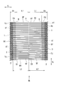
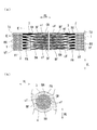
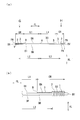
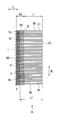
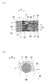
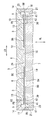
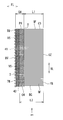
- FIG. 4 is a front plan view of a brush sheet (membrane layer/brush sheet) in which each cushion film layer is formed on each brush surface of the brush sheet in the film layer forming step (ST02) of the brush manufacturing method of the first embodiment.
- 4A is a partially enlarged view of FIG. 4A
- FIG. 4A is an enlarged view taken along arrow C and FIG. 4D
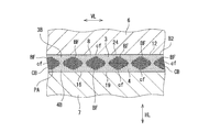
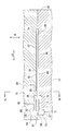
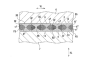
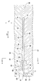
- FIG. 5B is an enlarged sectional view taken along line EE of FIG. 5A.
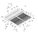
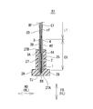
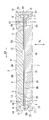
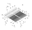
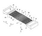
- FIG. 6 is a perspective view of a brush sheet in which each cushion film layer is formed on each brush surface and a base on the brush end side is molded in the molding step (ST04) of the brush manufacturing method of the first embodiment. It is a perspective view showing a brush X1. It is a figure which shows the brush X1 and is sectional drawing of FIG.
- FIG. 12A is an enlarged view seen from an arrow G in FIG. 12A and an enlarged view seen from an arrow H in FIG. 12B
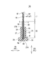
- FIG. 15 is sectional drawing which set the brush sheet (film layer and brush sheet) which formed the cushion film layer on one brush surface in the metal mold
- FIG. 15 is a partially enlarged view of FIG. 14.
- FIG. 16 is an enlarged view taken along the line JJ of FIG. 15.
- FIG. 7 is a perspective view of a brush sheet in which a cushion film layer is formed on one brush surface and a base is formed on each brush end side in the brush manufacturing method of the first embodiment. It is a perspective view showing a brush X2. It is a figure which shows the brush X2, Comprising: It is sectional drawing of FIG. It is a table top view which shows the brush body formed in the brush sheet formation process (ST21) of the manufacturing method of the brush of 2nd Embodiment.
- FIG. 7 is a perspective view of a brush sheet in which a cushion film layer is formed on one brush surface and a base is formed on each brush end side in the brush manufacturing method of the first embodiment. It is a perspective view showing a brush X2. It is a figure which shows the brush X2, Comprising: It is sectional drawing of FIG. It is a table top view which shows the brush body formed in the brush sheet formation process (ST21) of the manufacturing
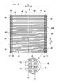
- FIG. 11 is a front plan view of a brush body (membrane layer/brush body) in which each cushion film layer is formed on each brush surface in the film layer forming step (ST22) of the brush manufacturing method of the second embodiment.
- FIG. 22 is an enlarged view of arrow K in FIG. 21.
- 22A is a view taken in the direction of arrow L in FIG. 22, and
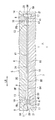
- FIG. 23B is an enlarged view taken along the line MM in FIG.
- It is sectional drawing which set the brush body (film layer/brush body) which formed each cushion film layer of each brush surface in the metal mold
- FIG. 25 is an enlarged view taken along line NN in FIG. 24.
- FIG. 26A is a view taken in the direction of arrow O in FIG. 26
- FIG. 27B is an enlarged sectional view taken along the line PP of FIG.
- FIG. 29 is an enlarged view of a QQ section of FIG. 28.
- FIG. 33 is a partially enlarged view of FIG. 32. It is a bb sectional enlarged view of FIG. It is a perspective view of the composite brush sheet which formed the base on each of the brush end sides in the forming step (ST34) of the brush manufacturing method of the third embodiment.
- 36A is a perspective view of the brush X3, and FIG.
- FIG. 36B is a partially enlarged perspective view of FIG. It is a figure which shows the brush X3, Comprising: It is sectional drawing of FIG.36(a). It is a front view which shows the composite brush body formed in the composite brush body formation process (ST41) of the manufacturing method of the brush of 4th Embodiment. It is sectional drawing which set the composite brush body to the metal mold
- FIG. 40 is a sectional view taken along line cc of FIG. 39.
- FIG. 41A is a view taken in the direction of arrow d in FIG. 41
- FIG. 42B is a partially enlarged view of FIG. 42A
- 42A is an enlarged view seen from an arrow e in FIG. 42A and an enlarged view seen from an arrow f in FIG. 42B
- FIG. 43B is an enlarged view taken along line gg in FIG. 43A.
- FIG. 16 is a perspective view of a composite brush sheet in which each cushion film layer is formed on each brush surface and a base is formed on each brush end side in the forming step (ST54) of the brush manufacturing method of the fifth embodiment.
- .. 48A is a perspective view of the brush X4, and FIG. 48B is a partially enlarged perspective view of FIG. 48A.
- FIG. 48 It is a figure which shows the brush X4 and is sectional drawing of FIG. 48 (a).
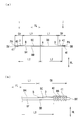
- (a) is a side view showing a composite brush sheet (film layer/composite brush sheet) having a cushion film layer formed on one brush surface
- FIG. 50B is a partially enlarged view of FIG. 50A is an enlarged view seen from the arrow i and j
- FIG. 50B is an enlarged view taken along the line kk of FIG. 51A.
- FIG. 53 is a partially enlarged cross-sectional view of FIG. 52.
- FIG. 54 is an enlarged cross-sectional view taken along the line ll of FIG. 53.
- FIG. 16 is a perspective view of a composite brush sheet in which a cushion film layer is formed on one brush surface and a base is formed on each brush end side in the forming method (ST54) of the brush manufacturing method of the fifth embodiment.
- .. (A) is a perspective view of the brush X5
- (b) is a partially expanded perspective view of FIG. 56(a). It is a figure which shows the brush X5, Comprising: It is sectional drawing of FIG.
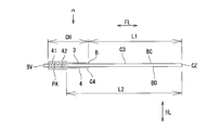
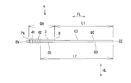
- FIG. 59 is a view on arrow m in FIG. 58.
- 59A is a view taken in the direction of arrow n in FIG. 59, and
- FIG. 60B is an enlarged cross-sectional view taken along line oo of FIG.
- FIG. 60 is sectional drawing which set the composite brush body which formed each cushion film layer on each brush surface in the metal mold
- FIG. 16 is a side view of a composite brush body (membrane layer/composite brush body) in which a cushion film layer is formed on one brush surface in the film layer forming step (ST62) of the brush manufacturing method of the sixth embodiment.
- 63A is a view taken in the direction of arrow q in FIG. 63
- FIG. 64B is an enlarged cross-sectional view taken along line rr of FIG. It is sectional drawing which set the composite brush body which formed the cushion film layer in one brush surface in the metal mold
- FIG. 16 is a side view of a composite brush body (membrane layer/composite brush body) in which a cushion film layer is formed on one brush surface in the film layer forming step (ST62) of the brush manufacturing method of the sixth embodiment.
- 63A is a view taken in the direction of arrow q in FIG. 63
- FIG. 64B is an
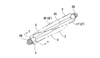
- FIG. 66 is an enlarged view taken along line ss of FIG. 65. It is a perspective view which shows a cleaner. It is a perspective view showing a rotary cleaning tool (brush, rotary shaft, gear shaft).
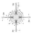
- FIG. 69 is a TT sectional view of FIG. 68. It is a schematic sectional drawing which shows the suction tool (head) of a vacuum cleaner.
- a method of manufacturing a brush according to the present invention will be described with reference to FIGS. 1 to 70. Hereinafter, a method of manufacturing the brush according to the first to sixth embodiments will be described.
- the brush manufacturing method according to the first embodiment includes a brush sheet forming step (ST01), a film layer forming step (ST02), a die setting step (ST03), and a base molding step (ST03). ST04) and a cutting step (ST05).
- the brush manufacturing method of the first embodiment includes a brush sheet forming step (ST01), a film layer forming step (ST01), a mold setting step (ST03), a base forming step (ST04), and a cutting step (ST05).
- the brushes X1 are manufactured by sequentially performing the steps.
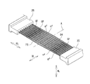
- ⁇ Brush sheet forming step (ST01)> In the brush sheet forming step (ST01), as shown in FIGS. 1 and 2, a brush sheet B1 (brush sheet member) in which a plurality of brush bristles BF made of weft HT are arranged in parallel is formed.
- the weft HT is composed of a carbon fiber bundle CB (fiber bundle) of a large number of carbon fibers cf, as shown in FIG.
- the carbon fiber cf is a PAN-based carbon fiber or a pitch-based carbon fiber, and is a long fiber (filament) having a fiber diameter fd.
- the PAN-based carbon fiber is used (hereinafter the same).
- the PAN-based carbon fiber is formed by firing an acrylic fiber at a high temperature and regularly arranging carbon molecules in a plurality of layers.
- the brush sheet B1 is formed by knitting various fibers with a warp knitting machine (not shown) such as a Russell knitting machine or a tricot knitting machine.
- the warp knitting machine inserts a weft HT made of a carbon fiber bundle CB (fiber bundle) of carbon fibers cf in a fiber direction FL of the carbon fiber bundle CB. It is folded back in U-shape on both sides and arranged in parallel, and each of the folded portions TU (near each folded portion TU) on both sides in the fiber direction FL is knitted into a warp yarn VT in a fiber orthogonal direction VL orthogonal to the fiber direction FL, Each turn-back portion TU of the HT (near each turn-back portion TU) is connected (restricted) by the warp VT. As shown in FIG. 1 and FIG.
- the warp knitting machine is configured such that each of the folded portions TU of the weft HT (carbon fiber bundle CB) has a plurality of warp textures formed of the warp VT, for example, a plurality of chain knitted portions 1 , 2 to connect (restrict) the folded-back portions TU (near the folded-back portions TU) of the weft HT (carbon fiber bundle CB) by the chain knitted portions 1 and 2.
- the warp knitting machine for example, as shown in FIG. 1, has two rows of chain knitting portions 1 and 2 (in the vicinity of each folding portion TU) on both sides of the carbon fiber bundle CB in the fiber direction FL.
- Each warp yarn VT is formed, and each folded-back portion TU of the weft yarn HT (carbon fiber bundle CB) is connected (restricted) by each chain knitting portion 1, 2.
- Each chain knitted part 2 (inner chain knitted part/inner warp) is adjacent to each chain knitted part 1 (outer chain knitted part/outer side warp) in the fiber direction FL of the carbon fiber bundle CB, and each chain knitted part 1 Is formed inside (between each chain knitting part 1).
- the fiber direction FL of the carbon fiber bundle CB is a weft direction in which the weft yarn HT extends
- the fiber orthogonal direction VL is a warp direction (direction in which the warp yarn VT extends) orthogonal to the weft direction.
- the warp knitting machine repeats folding back of the weft HT and inserting (braiding) into the chain knitted portions 1 and 2 (warp yarn VT/warp yarn structure) of each folded portion TU, A belt-shaped brush sheet B1 (brush sheet member) is formed.
- a brush sheet B1 in which a plurality of brush bristles BF made of the weft HT are arranged in parallel in the fiber orthogonal direction VL is formed.
- the brush bristles BF are formed between the chain knitting portions 2 (between the inner chain knitting portions) in the fiber direction FL of the carbon fiber bundle CB, and are arranged in parallel to the fiber orthogonal direction VL. Formed.
- the warp yarn VT may be woven into each of the folded portions TU on both sides of the weft yarn VT (carbon fiber bundle CB) to form the brush sheet B1 (plain weave brush sheet).
- ⁇ Film layer forming step (ST02)> In the film layer forming step (ST02), as shown in FIGS. 3 to 5, the soft resin PA is applied to the brush sheet B1 to form the cushion film layers 3 and 4 on the brush sheet B1.
- Soft resin PA means a flexible and elastic material, such as soft polyurethane resin, silicone resin, soft polyvinyl chloride resin, soft polyethylene resin, polyamide resin (nylon resin), soft epoxy resin, etc.
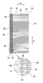
- the film layer forming step (ST02) As shown in FIGS. 3 to 5, between the chain knitted portions 2 (each inner chain knitted portion 2/each inner warp VT), the fiber direction FL of the carbon fiber bundle CB and A soft resin PA (soft polyurethane resin) is applied to one brush surface BA (brush surface) and the other brush surface BB (brush back surface) of the brush sheet B1 from the brush thickness direction HL of the brush sheet B1 orthogonal to the fiber orthogonal direction VL. Apply.
- a soft resin PA soft polyurethane resin
- the cushion film layers 3 and 4 are formed on the one brush surface BA and the other brush surface BB of each chain knitted part 2 (each inner chain knitted part 2/each warp VT) side.
- each of the cushion film layers 3 and 4 includes a brush sheet from a brush center A (brush center position) of each brush bristle BF (brush sheet B1) in the fiber direction FL of the carbon fiber bundle CB.
- a film layer starting point B film layer starting point position separating the brush length L1 on one and the other brush ends BX and BY sides of B1 and a film layer width CH between the brush ends BX and BY of the brush sheet B1 are provided. Is formed.
- the brush length L1 is a brush distance between the brush center A and each chain knitted part 2 (each inner chain knitted part 2/each warp VT) in the fiber direction FL of the carbon fiber bundle CB.
- each film layer starting point B of each cushion film layer 3, 4 is, as shown in FIGS. 3 to 5, each chain knitted part 2 (each inner chain knitted part 2) in the fiber direction FL of the carbon fiber bundle CB.
- /Cushion membrane layers 3 and 4 are formed inside the warp yarns VT (between the chain stitch portions 2), and the cushion film layers 3 and 4 are formed inside the chain stitch portions 2 (between the chain stitch portions 2). To be done.
- the cushion film layers 3 and 4 are, for example, as shown in FIGS. 3 to 5, the starting points of the film layers inside the chain knitted portions 2 (between the chain knitted portions 2).
- B and each chain knitted part 1 are formed with a film layer width CH.
- each of the cushion film layers 3 and 4 has a film layer width CH and is formed to extend in the fiber orthogonal direction VL.
- the soft resin PA moves from one and the other brush surfaces BA, BB of the brush sheet B1 to the brush bristles BF in the fiber orthogonal direction VL. It is applied between the brush bristles BF to continuously form the cushion film layers 3 and 4 in the fiber orthogonal direction VL.
- the soft resin PA is applied to the brush bristles BF of the brush surfaces BA and BB of the brush sheet B1 with the same or substantially the same thickness.
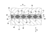
- the soft resin PA is, as shown in FIG. 5B, the carbon fibers of the carbon fiber bundle CB (weft HT) from one and the other brush surfaces BA and BB of the brush sheet B1. It is permeated (impregnated) between cf to cover each carbon fiber cf of the carbon fiber bundle CB.
- a soft resin PA water-soluble soft polyurethane resin
- soft resin PA water-soluble soft polyurethane resin
- Polyurethane resin is dried (cured) to integrally bond the soft resin PA (soft polyurethane resin) and the carbon fibers cf of the carbon fiber bundle CB.
- the soft resin PA is applied between the brush center A and each film layer starting point B in the fiber direction FL of the carbon fiber bundle CB. Not applied brush bristle area (brush bristle BF of brush length L1/carbon fiber cf) and application area (each cushion film layer 3, 4) in which soft resin PA is applied between each film layer start point B and each chain knitted portion 1 To form.
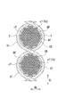
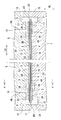
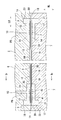
- the mold 5 is composed of an upper mold 6 and a lower mold 7, as shown in FIGS.
- the upper mold 6 and the lower mold 7 are formed in a block body as shown in FIGS. 6 and 7.
- the upper mold 6 has a brush sandwiching recess 8, a plurality (a pair) of molding recesses 9, and a plurality (a pair) of resin injection holes 10.
- the brush sandwiching recess 8 is formed at the center of the upper mold 6 in the width direction LR (left-right direction).
- the brush sandwiching recess 8 is recessed in a rectangular shape from the lower surface 11 of the upper mold 6 and is opened in the lower surface 11.
- the brush pinching recess 8 has a rectangular upper bottom plane 12.
- each molding recess 9 is formed on each side of the brush sandwiching recess 8 in the width direction LR (left-right direction) of the upper mold 6.
- Each molding recess 9 is formed continuously with the brush sandwiching recess 8 and has a main body molding recess 13 and a collar molding recess 14.
- the main body molding recess 13 is formed continuously on both sides of the brush sandwiching recess 8, as shown in FIGS. 6 and 7.
- the main body molding recess 13 is recessed from the upper bottom plane 12 of the brush holding recess 8 and is opened to the lower surface 11 of the upper mold 6 and the upper bottom plane 12 of the brush holding recess 8.
- the collar molding recess 14 is formed continuously with the main-body molding recess 13 in the width direction LR (left-right direction) of the upper mold 6.
- each molding recess 9 the collar molding recess 14 is recessed from the main body molding recess 13 and is opened in the lower surface 11 of the upper mold 6 and the main body molding recess 13.
- Each resin injection hole 10 is formed in the upper mold 6, as shown in FIGS. 6 and 7.
- Each resin injection hole 10 is opened in the main body molding recess 13 of each molding recess 9.
- the lower mold 7 has a brush sandwiching recess 16 and a plurality (a pair) of molding recesses 17.
- the brush sandwiching recess 16 is formed at the center of the lower mold 7 in the width direction LR (left-right direction).
- the brush pinching recess 16 is recessed in a rectangular shape from the upper surface 18 of the lower mold 7 and is opened in the upper surface 18.
- the brush pinching recess 16 has a rectangular lower base plane 19.
- each molding recess 17 is formed on each side of the brush sandwiching recess 16 in the width direction LR (left-right direction) of the lower mold 7.
- Each molding recess 17 is formed continuously with the brush sandwiching recess 16 and has a main body molding recess 20 and a collar molding recess 21.
- the main body molding recess 20 is formed continuously on both sides of the brush sandwiching recess 16, as shown in FIGS. 6 and 7.
- the main body molding recess 20 is recessed from the lower bottom flat surface 19 of the brush holding recess 16 and is opened to the upper surface 18 of the lower mold 7 and the lower bottom flat surface 19 of the brush holding recess 16.
- the collar molding recess 21 is formed continuously with the main body molding recess 20 in the width direction LR (left-right direction) of the lower mold 7, as shown in FIGS. 6 and 7.
- the collar forming recess 21 is recessed from the main body forming recess 20 and is opened in the upper surface 18 of the lower mold 7 and the main body forming recess 20.
- the brush sheet B1 (hereinafter, referred to as "membrane layer/brush sheet B2") on which the cushion film layers 3 and 4 are formed is, as shown in FIGS.
- the membrane layer/brush sheet B2 includes membrane layers 3A on the side of each chain knitting portion 2 (each side of the inner chain knitting portion 2/each warp VT side) of each cushion film layer 3, 4.
- the membrane layer/brush sheet B2 is formed into the respective molding concave portions by forming the respective membrane layer portions 3A and 4A (each cushion membrane layer 3 and 4) including the respective brush ends BX and BY and the chain knit portions 1 and 2.
- the remaining film layer portions 3B and 4B except the film layer portions 3A and 4A are arranged to face the locations 9 and 16 and face the brush sandwiching recesses 8 and 16, respectively.
- the film layer portions 3B and 4B of the film layer/brush sheet B2 are arranged so as to face the upper bottom plane 12 and the lower bottom plane 19.
- the upper mold 6 and the lower mold 7 are closed, and the upper mold 6 and the lower mold 7 are pressed against the membrane layer/brush sheet B2.
- the membrane layer/brush sheet B2 is sandwiched.
- the mold setting step (ST03) as shown in FIGS. 6 to 8, between the chain knitting portions 2 (each warp yarn VT), from the brush thickness direction HL of the film layer/brush sheet B2 to each cushion film.
- the upper mold 6 and the lower mold 6 are attached to the remaining film layer portions 3B and 4B except the film layer portions 3A and 3B on the side of the chain knitted portion 2 (on the side of the inner chain knitted portion 2/on the side of each warp VT) in layers 3 and 4.
- the mold 7 is pressed to set the membrane layer/brush sheet B2 in the mold 5.
- the upper bottom flat surface 12 of the brush sandwiching recess 8 is in surface contact with each film layer portion 3B from the brush thickness direction HL of the film layer/brush sheet B2 as shown in FIGS. 7 and 8. And then pressed.
- the lower bottom flat surface 19 of the brush sandwiching recess 16 is in surface contact with each film layer portion 4B from the brush thickness direction HL of the film layer/brush sheet B2, as shown in FIGS. 7 and 8. Be pressed against.
- the upper bottom plane 12 and the lower bottom plane 19 are, as shown in FIG.
- the fibers cf are pressed in liquid-tight contact with the membrane layers 3B, 4B over the fiber orthogonal direction VL while covering the fibers cf and deforming the membrane layers 3B, 4B located between all the brush bristles BF. ..
- the pressing force of the upper mold 6 and the lower mold 7 is absorbed by the deformation of the cushion film layers 3 and 4 (the film layer portions 3B and 4B).
- the upper bottom plane 12 and the lower bottom plane 19 are formed on the respective film layer portions 3B, 4B while deforming the respective film layer portions 3B, 4B of the cushion film layers 3, 4. It is pressed in surface contact. Accordingly, the pressing force of the upper mold 6 and the lower mold 7 can be prevented from acting as a concentrated load on each carbon fiber cf of each brush bristle BF (carbon fiber bundle CB), and each carbon of each brush bristle BF can be prevented.
- the fibers cf are not broken or broken by pressing the upper mold 6 and the lower mold 7 and are not damaged.
- the upper mold 6 and the lower mold 7 press the cushion film layers 3 and 4 while contacting the lower surface 11 and the upper surface 18, as shown in FIGS. To be closed.
- each molding space 23 is a space for molding the base 25 (see FIGS. 10 and 11) of the brush X1.
- each brush space 24 When the upper mold 6 and the lower mold 7 are closed, the brush sandwiching recesses 8 and 16 form the brush spaces 24 as shown in FIG. 7.
- the upper bottom plane 12 of the upper mold 6 and the lower bottom plane 19 of the lower mold 7 are brought into surface contact with the respective film layer portions 3B and 4B (a part of the cushion film layers 3 and 4). By pressing, each molding space 23 is liquid-tightly sealed.
- each of the film layer portions 3A and 4A (a part of each of the cushion film layers 3 and 4) is moved from the brush space 24 into each molding space 23 in the fiber direction FL of the carbon fiber bundle CB. It projects and is arranged in each molding space 23.
- the protrusion amount of each film layer portion 3A and 4A is 0.5 mm or more.
- the amount of protrusion of each of the membrane layer portions 3A and 4A is the length of protrusion from the brush space 24 into each of the molding spaces 23 in the fiber direction FL of the carbon fiber bundle CB (the same applies hereinafter).
- the cushion film layers 3 and 4 are continuously arranged in the brush space 24 and the molding spaces 23 in the fiber direction FL of the carbon fiber bundle CB, as shown in FIG. 7.
- ⁇ Base forming process (ST04)> In the base forming step (ST04), as shown in FIGS. 6 and 7, the brushes of the film layer/brush sheet B2 are pressed from the remaining film layer portions 3B and 4B on which the upper mold 6 and the lower mold 7 are pressed. The ends 3X and 3Y are filled with the synthetic resin PB, and the bases 25 are formed on the brush ends BX and BY of the membrane layer/brush sheet B2, respectively.
- the synthetic resin PB is filled into the molding spaces 23 from the resin injection holes 10.
- the synthetic resin PB is, as shown in FIGS. 6 and 7, the brush ends BX and BY of the film layer/brush sheet B2, the chain knitting portions 1 and 2 (each warp yarn VT). ), and each film layer part 3A, 4A (a part of each cushion film layer 3, 4), and it is filled in each molding space 23.
- the synthetic resin PB filled in each molding space 23 is dammed by the respective film layer portions 3B and 4B which are deformed by being in surface contact with the upper bottom plane 12 and the lower bottom plane 19.
- the synthetic resin PB can be prevented from flowing into the brush space 24 and entering the carbon fibers cf of the brush bristles BF (carbon fiber bundles CB), and the flexibility of the brush bristles can be secured to ensure that the brushes are not brushed. It can exert the function of hair.
- the base molding step (ST04) when each molding space 23 is filled with the synthetic resin PB, the mold 5 (the upper mold 6 and the lower mold 7) is cooled and the synthetic resin PB is cured to form a film.
- the base 25 is fixed (fixed) to each of the brush ends BX and BY of the layer/brush sheet B1.
- the synthetic resin PB filled in each molding space 23 is cured, the upper mold 6 and the lower mold 7 are opened, and the membrane layer/brush sheet B1 on which each base 25 is molded is formed. Remove from mold 5.
- ⁇ Cutting process (ST05)> In the cutting step (ST05), as shown in FIGS. 9 and 10, the brush sheet B1 is placed between the cushion membrane layers 3 and 4 formed by forming the bases 25 on the membrane layer/brush sheet B2 in the fiber orthogonal direction VL. Disconnect.
- the membrane layer/brush sheet B2 on which the bases 25 are formed has fiber crossing at the brush center A of the brush sheet B1 between the cushion membrane layers 3 and 4, as shown in FIG. It is cut in the direction VL. All the brush bristles BF of the brush sheet B1 are cut in the fiber orthogonal direction VL at the brush center A of the brush sheet B1. As a result, in the cutting step (ST05), the brush sheet B1 is cut to be divided into a plurality (a pair) of brushes X1, as shown in FIGS. 10 and 11.
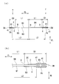
- the brush X1 includes a base 25 and a brush body C1.
- the base 25 has a base body 27 and a plurality (one pair) of collar portions 28.
- the base body 27 is formed in a rectangular parallelepiped having a rectangular cross section.
- Each flange 28 is formed in a rectangular parallelepiped having a rectangular cross section.
- Each collar 28 is formed integrally with the base body 27.
- Each of the collar portions 28 is located on one table end 27A side of the table body 27 in the table height direction FD (fiber direction FL) of the base 25, and in the table width direction HD orthogonal to the table height direction FD, It is formed so as to project from the base body 27.
- the brush body C1 includes a plurality of brush bristles BF, a plurality (a pair) of chain knitted portions 1 and 2 (each warp VT), and a plurality (a pair) of cushion film layers 3 and 4.
- Each of the brush bristles BF is formed by juxtaposing a large number of carbon fiber bundles CB of carbon fibers cf folded back in a U shape in a fiber orthogonal direction VL orthogonal to the fiber direction FL.
- the chain knitted portion 1 (warp yarn VT) extends in the fiber orthogonal direction VL.
- the chain knitted portion 1 restrains the folded-back portion TU (near the folded-back portion TU) of each brush bristle BF (carbon fiber bundle CB) to connect each brush bristle BF.
- the chain knitted portion 2 (warp yarn VT) extends in the fiber orthogonal direction VL.
- the chain stitch portion 2 is located between the other brush end CX (brush tip) of the brush body C1 and the chain stitch portion 1, and is disposed adjacent to the chain stitch portion 1.
- the chain knitted portion 2 restrains the brush bristles BF (carbon fiber bundle CB) and connects the brush bristles BF.
- the cushion film layer 3 is one brush surface BA (brush surface) of the brush body C1 from the brush thickness direction HL of the brush body C1 orthogonal to the fiber direction FL and the fiber orthogonal direction VL. Is formed.
- the cushion film layer 4 is formed on the other brush surface BB (back surface of the brush) of the brush body C1 in the brush thickness direction HL.
- the cushion film layers 3 and 4 are made of a soft resin PA (soft polyurethane resin).
- each of the cushion film layers 3 and 4 is brushed from the other brush end CX (brush tip) of the brush body C1 to the one brush end BX side of the brush body C1 in the fiber direction FL.
- a film layer width CH is formed between the film layer starting point B (film layer starting point position) separating the length L1 and one brush end BX of the brush body C1.
- each of the cushion film layers 3 and 4 has, for example, a film layer starting point B on the brush end CX side (between the chain knitting part 2 and the brush tip CX) of the chain knitting part 2 and the chain knitting part 1. Is formed with a film layer width CH between them.
- each of the cushion film layers 3 and 4 has a film layer width CH and is formed to extend in the fiber orthogonal direction.
- the cushion film layers 3 and 4 are arranged (formed) between the brush surfaces BA and BB of the brush body C1 and the carbon fibers Cf of the brush bristles BF (carbon fiber bundle CB), respectively. Cover each carbon fiber cf. As shown in FIG. 10, the cushion film layers 3 and 4 are continuously formed (arranged) in the fiber orthogonal direction VL across the brush surfaces BA and BB of the brush body C1 and between the brush bristles BF. ..
- the brush bristles BF carbon fiber bundles CB
- the brush body C1 is embedded in the base 25 from one brush end BX and is fixed to the base 25.
- the respective film layer portions 3A and 4A on the side of the chain knitted portion 2 (the warp VT) of the respective cushion film layers 3 and 4 are embedded in the base 25, and the rest except the respective film layer portions 3A and 4A.
- the film layer portions 3B and 4B of the above are projected from the other base end 27B of the base body 27 and fixed to the base 25.
- the film layer portions 3A and 4A are covered with a base 25 (synthetic resin PB) and integrally fixed to the base 25, as shown in FIG.
- the brush X1 includes one brush end BX of the brush body C1, each chain knitted part 1 and 2 (each warp VT) and each film layer part 3A and 4A (a part of each cushion film layer 3 and 4). It is embedded in the base 25 and one brush end CX side (brush tip side) of the brush body C1 and each film layer part 3B, 4B from the other base end 27B (base end of the base 25) of the stand body 27. It is formed to project.
- the brush X1 protects the carbon fibers cf of the brush bristles BF (carbon fiber bundle CB) with the cushion film layers 3 and 4 of the soft resin PA.
- the cushion film layers 3 and 4 (soft resin PA) are continuously arranged inside the base 25 and outside the base 25 with the base end 27B of the base 25 (base main body 27) as a boundary. There is.
- each brush bristle FB (each carbon fiber cf) is bent in multiple directions (fiber orthogonal direction VL, brush thickness direction HL)
- the force due to the bending is applied to each cushion film layer 3, 4
- each carbon fiber cf of each brush bristle BF should be broken and broken from the base end 27B of the base 25 (base body 27) as a starting point (base point). Is suppressed (reduced).
- the cushion film layer is formed on one brush surface BA (or the brush surface BB) of the brush surfaces BA, BB on both sides of the brush sheet B1. 3 (or the cushion film layer 4) may be formed to manufacture the brush X2 (see FIGS. 18 and 19), which will be described below.
- the same reference numerals as those in FIGS. 1 to 11 denote the same members and the same configurations, and thus detailed description thereof will be omitted.
- ⁇ Film layer forming step (ST02)> In the film layer forming step (ST02), as shown in FIGS. 12 and 13, the soft resin PA is applied to the brush sheet B1 to form the cushion film layer 3 (or the cushion film layer 4) on the brush sheet B1.
- the film layer forming step (ST02) As described with reference to FIGS. 3 to 5, between the chain knitting portions 2 (each warp yarn VT), one of the brush sheets B1 from the brush thickness direction HL of the brush sheet B1.
- the soft resin PA soft polyurethane resin
- the soft resin PA soft polyurethane resin
- the cushion film layer 3 is formed on the one brush surface BA on the side of each chain knitted part 2 (each inner chain knitted part 2/warp VT) by covering with the soft resin PA.
- the cushion film layer 3 has, for example, the film layer starting point B inside the chain knitted portions 2 (between the chain knitted portions 2), as described in FIGS. 3 to 5. , And each chain knitted part 1 (each outer chain knitted part 1/each warp VT) having a film layer width CH (see FIGS. 12 and 13).
- the soft resin PA is, in the fiber orthogonal direction VL, from the one brush surface BA of the brush sheet B1 to each of the brush bristles BF and each of the brushes, as described with reference to FIGS. 3 to 5. It is applied between the bristles BF to continuously form the cushion film layer 3 in the fiber orthogonal direction VL.
- the soft resin PA is applied on one brush surface BA of the brush sheet B1 with the same or substantially the same thickness.
- the soft resin PA permeates (impregnates) between the carbon fibers cf of the carbon fiber bundle CB (weft VT) from one brush surface BA of the brush sheet B1 as shown in FIG. 13(b). 3) and covers each carbon fiber cf of the carbon fiber bundle CB.
- the soft resin PA is applied between the brush center A and each film layer start point B in the fiber direction FL of the carbon fiber bundle CB.
- An application area (cushion film layer 3) in which the soft resin PA is applied is formed between the non-brush bristle area and each film layer starting point B and each chain knitted portion 1.
- the brush sheet B1 on which the cushion film layer 3 is formed (hereinafter, referred to as “membrane layer/brush sheet B3”) has one brush surface BA and one brush surface BA as shown in FIGS.
- Each cushion film layer 3 is directed toward the brush nipping recess 8 and each molding recess 9 of the upper mold 6, and the other brush surface BB is directed to each brush nipping recess 16 of the lower mold 7 and each molding recess 17 thereof. It is arranged between the upper mold 6 and the lower mold 7. As shown in FIG.
- the membrane layer/brush sheet B3 has a cavity for forming the membrane layer portion 3A on each side of the chain knitting portion 2 (each side chain knitting portion 2 side/each warp VT side) of the cushion membrane layer 3 in each molding recess. 9 and 17, and the remaining film layer portion 3B excluding each film layer portion 3A is located in the brush sandwiching recesses 8 and 16, and is disposed between the upper mold 6 and the lower mold 7.
- the membrane layer/brush sheet B3 faces the molding recesses 9 and 16 with the membrane layer portion 3A (a part of the cushion membrane layer 3) including the brush ends BX and BY and the chain knit portions 1 and 2, respectively.
- the remaining film layer portion 3B except the film layer portion 3A is arranged so as to face the brush sandwiching recesses 8 and 16.
- the film layer portion 3B of the film layer/brush sheet B3 is arranged so as to face the upper bottom plane 12 of each brush sandwiching recess 8.
- the upper mold 6 and the lower mold 7 are closed, and the upper mold 6 and the lower mold 7 are pressed against the membrane layer/brush sheet B3.
- the membrane layer/brush sheet B2 is sandwiched.
- the mold setting step (ST03) as shown in FIG. 14 to FIG. 16, from the brush thickness direction HL of the film layer/brush sheet B3, each chain knitted part 2 side (each inner chain knitted part) in the cushion film layer 3 is The upper die 6 is pressed against the remaining film layer portion 3B except the film layer portion 3A (2 side/each warp VT side).
- the mold setting step (ST03) as shown in FIGS.
- the film layer/brush between each chain knitting part 2 (each warp yarn VT) from the brush thickness direction HL of the film layer/brush sheet B3.
- the lower die 7 is pressed against the other brush surface BB of the sheet B3 to set the membrane layer/brush sheet B3 in the die 5.
- the upper bottom flat surface 12 of the brush sandwiching recess 8 is pressed in surface contact with each film layer portion 3B from the brush thickness direction HL of the film layer/brush sheet B3 as shown in FIG. ..
- the lower bottom flat surface 19 of the brush sandwiching recess 16 is pressed against the other brush surface BB (back surface of the brush) from the brush thickness direction HL of the film layer/brush sheet B3, as shown in FIG. ..
- the upper bottom plane 12 and the lower bottom plane 19 cover each carbon fiber cf of a part of all the brush bristles BF, and all the brush bristles BF. While deforming the membrane layer portion 3B located between the BFs, the membrane layer portion 3B and the other brush surface BB are surface-contacted and pressed in the fiber orthogonal direction VL.
- the pressing force of the upper mold 6 and the lower mold 7 is absorbed by the deformation of each cushion film layer 3 (each film layer portion 3B).
- the upper bottom plane 12 and the lower bottom plane 19 deform each film layer portion 3B of each cushion film layer 3 and also each film layer portion 3B and the other brush surface BB (brush surface). It is pressed in contact with the back side). Accordingly, the pressing force of the upper mold 6 and the lower mold 7 can be prevented from acting as a concentrated load on each carbon fiber cf of each brush bristle BF (carbon fiber bundle CB), and each carbon of each brush bristle BF can be prevented.
- the fibers cf are less susceptible to damage such as breaking and breaking due to the pressing force of the upper mold 6 and the lower mold 7.
- the upper mold 6 and the lower mold 7 press the cushion film layer 3 and the other brush surface BB while pressing the lower surface 11 and the upper surface 18 as shown in FIGS. 14 and 16. Is abutted and closed.
- each membrane layer portion 3A (a part of each cushion membrane layer 3) protrudes from the brush space 24 into each molding space 23 in the fiber direction FL of the carbon fiber bundle CB, as shown in FIG. It is arranged in the molding space 23.
- the cushion film layer 3 is continuously arranged in the brush space 24 and each molding space 23, as shown in FIG.
- ⁇ Base forming process (ST04)> In the base forming step (ST04), as shown in FIGS. 14 and 15, the remaining film layer portion 3B on which the upper mold 6 and the lower mold 7 are pressed, and the film layer/brush sheet B2 from the other brush surface BB.
- the synthetic resin PB is filled into the brush ends 3X and 3Y of the above, and the base 25 is formed on each of the brush ends BX and BY of the membrane layer/brush sheet B2.
- each molding space 23 from each resin injection hole 10.
- the synthetic resin PB is, as shown in FIGS. 14 and 15, each brush end BX, BY of the film layer/brush sheet B2, each chain knitted part 1 and 2, the film layer part 3A.
- the molding space 23 is filled with (a part of the cushion film layer 3) and a part of the brush surface BB.
- the base molding step (ST04) after curing the synthetic resin PB, the upper mold 6 and the lower mold 7 are opened, and the film layer/brush sheet B3 on which each base 25 is molded is taken out of the mold 5.
- ⁇ Cutting process (ST05)> In the cutting step (ST05), as shown in FIGS. 17 and 18, the brush sheet B1 is cut in the fiber orthogonal direction VL between the cushion membrane layers 3 formed by forming the bases 25 on the membrane layer/brush sheet B3. To do.
- the membrane layer/brush sheet B3 on which the bases 25 are formed is, as shown in FIG. 17, at the brush center A of the brush sheet B1 between the cushion membrane layers 3, the fiber orthogonal direction VL. To be disconnected. All the brush bristles FG of the brush sheet B1 are cut in the fiber orthogonal direction VL at the brush center A of the brush sheet B1. As a result, in the cutting step (ST05), the brush sheet B1 is cut to be divided into a plurality (a pair) of brushes X2, as shown in FIGS. 18 and 19.
- the brush X2 includes a base 25 and a brush body C2 (membrane layer/brush body C2).
- the base 25 has a base body 27 and a plurality of (a pair of) flanges 28, as described with reference to FIGS. 10 and 11.
- the brush body C2 has a plurality of brush bristles BF, a plurality (a pair) of chain knitted portions 1 and 2 (each warp YT), and a cushion film layer 3 as in the case described with reference to FIGS. 10 and 11 (FIG. 18). And FIG. 19).
- the cushion film layer 3 is formed on one brush surface BA (brush surface) of the brush body C2 from the brush thickness direction HL of the brush body C2.
- the cushion film layer 3 includes a film start point B that separates the brush length L1 from the other brush end CY (brush tip) of the brush body C2 to one brush end BX of the brush body C2, and the brush body C2.
- the brush body C2 in the fiber direction FL of the carbon fiber bundle CB, the brush region (brush length L1) in which the cushion film layer 3 is not formed between the other brush end CY (brush tip) and the film layer start point B.
- the area (cushion area) of the cushion film layer 3 is formed between the brush bristles BF/carbon fiber cf), the film layer starting point B, and the chain knit portion 1.
- the brush bristles BF carbon fiber bundles CB
- the brush body C2 is embedded in the base 25 from one brush end BX and is fixed to the base 25.
- the film layer portion 3A on the chain knitting portion 2 side of the cushion film layer 3 is embedded in the base 25, and the remaining film layer portion 3B excluding the film layer portion 3A is provided on the other base end 27B of the base body 27. It projects from and is fixed to the base 25.
- the brush X2 has one brush end BX of the brush body C2, each chain knitted portion 1, 3 and the film layer portion 3A (a part of the cushion film layer 3) embedded in the base 25, and the brush body
- the other brush end CX side of C2 (brush tip side) and the film layer portion 3B are formed to project from the other stand end 27B of the stand body 27 (stand end of the base 25).
- the brush X2 protects the carbon fibers cf of the brush bristles BF (carbon fiber bundle CB) by covering them with the cushion film layer 3 of the soft resin PA.
- the cushion film layer 3 soft resin PA
- the cushion film layer 3 soft resin PA
- the brush X2 even if each of the brush bristles BF (each of the carbon fibers cf) is bent in multiple directions (the fiber orthogonal direction VL and the brush thickness direction HL), the bending force causes the cushion film layer 3 (soft resin).
- each carbon fiber cf of each brush bristles BF is suppressed from being broken and broken from the base end 27B of the base 25 (base main body 27) as a starting point (base point) ( Will be reduced).
- the brush manufacturing method of the second embodiment includes a brush body forming step (ST21), a film layer forming step (ST22), a mold setting step (ST23), and a base molding step (ST23). ST24).
- the brush manufacturing method of the second embodiment is carried out in the order of a brush body forming step (ST21), a film layer forming step (ST22), a mold setting step (ST23), and a base molding step (ST24), and a brush is formed.
- X1 (see FIGS. 10 and 11) is manufactured.
- ⁇ Brush body forming step (ST21)> In the brush body forming step (ST21), as shown in FIG. 20, a plurality of brush bristles BF composed of a carbon fiber bundle FB of a large number of carbon fibers cf are arranged in a fiber orthogonal direction VL orthogonal to the fiber direction FL of the carbon fiber bundle FB. In parallel, the brush body C1 is formed.
- the carbon fiber bundle CB (weft VS) is cut at the brush center A of the brush sheet B1 to form the brush body C1.
- the brush body C1 is composed of a plurality of brush bristles BF on one side, which are obtained by cutting the brush sheet B1 in the fiber orthogonal direction VL at the brush center A of the brush sheet B1, and chain knitted portions 1 and 2 (see FIG. 20). ).
- the brush body C1 has a plurality of brush bristles BF and a plurality (a pair) of chain knitted portions 1 and 2 (each warp VS), as shown in FIG. As shown in FIG.
- each of the brush bristles BF is formed by arranging a large number of carbon fiber bundles CB of carbon fibers cf folded back in a U shape in the fiber orthogonal direction VL orthogonal to the fiber direction FL.
- the chain knitted portions 1 and 2 connect (restrict) the folded portions TU (near the folded portions TU) of the brush body C1.
- each of the brush bristles BF is formed between the other brush end CX (brush tip) of the brush body C1 and the chain knitting portion 2 in the fiber direction FL of the carbon fiber bundle, and is in the fiber orthogonal direction. It is formed in parallel with VL.
- a plurality of warp yarns VT are laid in parallel in the fiber direction FL (weft direction) of the carbon fiber bundle CB and woven into each brush bristles BF.
- ⁇ Film layer forming step (ST22)> In the film layer forming step (ST22), as shown in FIGS. 21 to 23, the soft resin PA is applied to the brush body C1 to form the cushion film layers 3 and 4 on the brush body C1.
- the film layer forming step (ST22) As shown in FIG. 21 to FIG. 23, one of the brush body C1 from the brush thickness direction HL of the brush body C1 orthogonal to the fiber direction FL of the carbon fiber bundle CB and the fiber orthogonal direction VL.
- the soft resin PA is applied to the brush surface BA (brush surface) and the other brush surface BB (brush back surface).
- the soft resin PA is applied to each of the brush surfaces BA and BB of the brush body C1, and the carbon fibers cf of the brush bristles BF are covered with the soft resin PA to form the brush body C1.
- the cushion film layers 3 and 4 are formed on one brush surface BA on one brush end BX side (chain knitting portion 2 side/warp yarn VT side) and the other brush surface BB, respectively.
- each of the cushion film layers 3 and 4 has a brush length L1 from the other brush end CX of the brush body C1 to the one brush end BX side in the fiber direction FL of the carbon fiber bundle CB.
- a film layer width CH is formed between the separating film layer starting point B and one brush end BX of the brush body C1.
- the film layer starting point B of each of the cushion film layers 3 and 4 is located inside the chain knitted portion 2 (the warp yarn VT) (located between one brush end CX and the chain knitted portion 2), and the cushion film layer 3 is formed. , 4 are formed inside the chain knitted portion 2.
- each of the cushion film layers 3 and 4 is, for example, as shown in FIGS. 21 to 23, inside the chain stitch portion 2 (between the chain stitch portion 2 and the other brush end CX).
- the film layer width CH is formed between the film layer starting point B and the chain knitted portion 1 (the warp yarn VT).
- each of the cushion film layers 3 and 4 has a film layer width CH and is formed to extend in the fiber orthogonal direction VL.
- the soft resin PA moves from one and the other brush surfaces BA and BB of the brush body C1 to the brush bristles BF and each in the fiber orthogonal direction VL. It is applied between the brush bristles BF to continuously form the cushion film layers 3 and 4 in the fiber orthogonal direction VL.
- the soft resin PA is applied to the brush bristles BF of the brush surfaces BA and BB of the brush body C1 with the same or substantially the same thickness.
- the soft resin PA is, as shown in FIG. 23(b), between the one and the other brush surfaces BA and BB of the brush body C1 and the respective carbon fibers cf of the carbon fiber bundle CB. It is permeated (impregnated) and covers each carbon fiber cf of the carbon fiber bundle CB.
- the soft resin PA water-soluble soft polyurethane resin
- the soft resin PA water-soluble soft polyurethane resin
- (Polyurethane resin) is dried (cured), and the soft resin PA (soft polyurethane resin) and the carbon fibers cf of the carbon fibers CB are integrally bonded.
- the soft resin PA is provided between the other brush end CX and the film layer starting point B in the fiber direction FL of the carbon fiber bundle CB.
- An application area (each cushion film layer 3) in which the soft resin PA is applied between the non-applied brush bristle area (brush bristle BF of the brush length L1/carbon fiber cf) and the membrane layer start point B and the chain knitted portion 1 (warp VT). , 4) is formed.
- the mold 55 is composed of an upper mold 56 and a lower mold 57, as shown in FIGS.
- the upper die 56 and the lower die 57 are formed in a block body as shown in FIG.
- the upper die 56 has a brush sandwiching recess 58, a molding recess 59, and a resin injection hole 60.
- the brush sandwiching recess 58 is formed at the center of the upper mold 56 in the width direction LR (left-right direction).
- the brush sandwiching recess 58 is recessed in a rectangular shape from the lower surface 61 of the upper mold 56 and is opened in the lower surface 61.
- the brush pinching recess 58 has a rectangular upper bottom flat surface 62.
- the molding recess 59 is formed on one end side (left end side) of the brush holding recess 58 in the width direction LR (left-right direction) of the upper mold 56.
- the molding recess 59 is formed continuously with the brush sandwiching recess 58 and has a main body molding recess 63 and a collar molding recess 64.
- the main body molding recess 63 is formed continuously with one end of the brush sandwiching recess 58, as shown in FIG.
- the main body molding recess 63 is recessed from the upper bottom flat surface 62 of the brush holding recess 58, and is opened to the lower surface 61 of the upper mold 56 and the upper bottom flat surface 62 of the brush holding recess 58.
- the collar forming recess 64 is formed continuously with the main body forming recess 63 in the width direction LR (left-right direction) of the upper die 56, as shown in FIG.
- the collar molding recess 64 is recessed from the main body molding recess 63 and opened to the lower surface 61 of the upper die 56 and the main body molding recess 63.
- the resin injection hole 60 is formed in the upper mold 56 as shown in FIG.
- the resin injection hole 60 is opened in the main body forming recess 63 of the forming recess 59.
- the lower die 57 has a brush sandwiching recess 66 and a molding recess 67.
- the brush sandwiching recess 66 is formed at the center of the lower die 57 in the width direction LR (left-right direction).
- the brush sandwiching recess 66 is recessed in a rectangular shape from the upper surface 68 of the lower mold 57 and is opened in the upper surface 68.
- the brush pinching recess 66 has a rectangular lower bottom flat surface 69.
- the molding recess 67 is formed on one end side (left end side) of the brush holding recess 66 in the width direction LR (left-right direction) of the lower mold 57.
- the molding recess 67 is formed continuously with the brush sandwiching recess 66, and has a main body molding recess 70 and a collar molding recess 71.
- the main body forming recess 70 is continuously formed on one end side (left end side) of the brush sandwiching recess 66, as shown in FIG.
- the main body molding recess 70 is recessed from the lower bottom flat surface 69 of the brush holding recess 66, and is opened to the upper surface 68 of the lower mold 57 and the lower bottom flat surface 69 of the brush holding recess 66.
- the collar forming recess 71 is formed continuously with the main body forming recess 70 in the width direction LR (left-right direction) of the lower die 57, as shown in FIG.
- the collar molding recess 71 is recessed from the main body molding recess 70 and is opened to the upper surface 68 of the lower mold 57 and the main body molding recess 70.
- the brush body C1 on which the cushion film layers 3 and 4 are formed (hereinafter, referred to as "membrane layer/brush body C1") is one of the brushes as shown in FIGS. 24 and 25.
- the surface BA and the cushion film layer 3 are directed toward the brush nipping recess 58 and the molding recess 59 of the upper mold 56, and the other brush surface BB and the cushion film layer 4 are directed toward the brush nipping recess 66 and the molding recess of the lower mold 57. It is arranged between the upper die 56 and the lower die 57 toward the place 67. As shown in FIG.
- the membrane layer/brush body C1 includes the respective membrane layer portions 3A and 4A on one brush end BX side (chain knitting portion 2 side/warp yarn VT side) of the cushion membrane layers 3 and 4, respectively.
- the upper die 56 and the lower die are located in the molding recesses 59 and 67, and the remaining film layer portions 3B and 4B except the film layer portions 3A and 4A are located in the brush sandwiching recesses 58 and 66. It is arranged between the molds 57.
- the membrane layer/brush body C1 is provided with one brush end BX and each membrane layer portion 3A, 4A including each chain knitting portion 1, 2 (a part of each cushion membrane layer 3, 4) in each molding recess.
- the film layer portions 3B and 4B of the film layer/brush body C1 are arranged to face the upper bottom plane 62 and the lower bottom plane 69.
- the upper mold 56 and the lower mold 57 are closed and the upper mold 56 and the lower mold 57 are pressed against the membrane layer/brush body C1.
- the upper die 56 and the lower die 57 are pressed against the remaining membrane layer portions 3B and 4B except the respective membrane layer portions 3A and 4A (the portion 2 side/the warp VT side) to form the membrane layer/brush body C1 into the die.
- Set to 55 the remaining membrane layer portions 3B and 4B except the respective membrane layer portions 3A and 4A (the portion 2 side/the warp VT side) to form the membrane layer/brush body C1 into the die.
- the upper bottom flat surface 62 of the brush sandwiching recess 58 is in surface contact with the film layer portion 3B from the brush thickness direction HL of the film layer/brush body C1 as shown in FIGS. 24 and 25. It is pressed.
- the lower bottom flat surface 69 of the brush sandwiching recess 66 is in surface contact with the film layer portion 4B from the brush thickness direction HL of the film layer/brush body C1 as shown in FIGS. 24 and 25. It is pressed.
- the upper bottom plane 62 and the lower bottom plane 69 are, as shown in FIG.
- the pressing force of the upper mold 56 and the lower mold 57 is absorbed by the deformation of the cushion film layers 3 and 4 (the film layer portions 3B and 4B).
- the upper bottom plane 62 and the lower bottom plane 69 are formed on the respective film layer portions 3B and 4B while deforming the respective film layer portions 3B and 4B of the cushion film layers 3 and 4. It is pressed in surface contact.
- the pressing force of the upper mold 56 and the lower mold 57 can be prevented from acting as a concentrated load on each carbon fiber cf of each brush bristle BF (carbon fiber bundle CB), and each carbon of each brush bristle BF can be prevented.
- the fibers cf are not broken or damaged by pressing the upper mold 56 and the lower mold 57.
- the upper mold 56 and the lower mold 57 press the cushion film layers 3 and 4 while contacting the lower surface 61 and the upper surface 68, as shown in FIGS. To be closed.
- the molding space 73 is a space for molding the base 25 (see FIGS. 10 and 11) of the brush X1.
- the brush sandwiching recesses 58, 66 form a brush space 74 as shown in FIG.
- the brush space 74 presses the upper bottom plane 62 of the upper mold 56 and the lower bottom plane 69 of the lower mold 57 into surface contact with each of the film layer portions 3B and 4B (a part of each cushion film layer 3 and 4). By attaching it, it is liquid-tightly sealed from the molding space 73.
- each membrane layer part 3A, 4A protrudes from the brush space 74 into the molding space 73 in the fiber direction FL of the carbon fiber bundle CB, as shown in FIG. And is placed in the molding space 73.
- the cushion film layers 3 and 4 are continuously arranged in the brush space 74 and the molding space 73 in the fiber direction FL of the carbon fiber bundle CB.
- ⁇ Base forming process (ST24)> In the base forming step (ST24), as shown in FIG. 24, one brush end BX of the film layer/brush body C1 is pressed from the remaining film layer portions 3B and 4B on which the upper mold 56 and the lower mold 57 are pressed.
- the side (chain side 2 side/warp VT side) is filled with synthetic resin PB, and the base 25 is formed on one brush end BX side of the membrane layer/brush body C1.
- the molding space 73 is filled with the synthetic resin PB from the resin injection hole 60.
- the synthetic resin PB is, as shown in FIG. 24, one brush end BX of the film layer/brush body C1, each chain knitted part 1 and 2 (each warp yarn VT), and each film.
- the molding space 73 is filled while covering the layer portions 3A and 4A (a part of the cushion film layers 3 and 4).
- the synthetic resin PB filled in the molding space 73 is dammed by the respective film layer portions 3B and 4B which are deformed by being in surface contact with the upper bottom plane 62 and the lower bottom plane 69, and are molded.
- the synthetic resin PB can be prevented from flowing into the brush space 74 and invading the carbon fibers cf of the brush bristles BF (carbon fiber bundle CB), thereby ensuring the flexibility of the brush bristles and ensuring that the brushes It can exert the function of hair.
- the base molding step (ST24) when the molding space 73 is filled with the synthetic resin PB, the mold 55 (the upper mold 56 and the lower mold 57) is cooled, the synthetic resin PB is cured, and the film layer is formed.
- the base 25 is formed on one brush end BX side of the brush body C1.
- the base molding step (ST24) when the synthetic resin PB filled in the molding space 23 is cured, the upper mold 56 and the lower mold 57 are opened to mold the film layer/brush body C1 on which the base 25 is molded into a mold. Take out from 55. As a result, the brush X1 is manufactured (see FIGS. 10 and 11).
- the cushion film layer is formed on one brush surface BA (or the brush surface BB) of the brush surfaces BA and BB on both sides of the brush body C1.
- 3 (cushion film layer 4) may be formed to manufacture the brush X2 (see FIGS. 18 and 19), which will be described below.
- ⁇ Film layer forming step (ST22)> In the film layer forming step (ST22), as shown in FIGS. 26 and 27, the soft resin PA is applied to the brush body C1 to form the cushion film layer 3 (or the cushion film layer 4) on the brush body C1.
- the soft resin PA soft polyurethane resin
- the soft resin PA is applied to the one brush surface BA of the brush body C1 from the brush thickness direction HL in the same manner as described with reference to FIGS. 21 to 23. Apply (see FIGS. 26 and 27).
- the soft resin PA is applied to one brush surface BA of the brush body C1 and the carbon fiber cf of each brush bristle BF is covered with the soft resin PA.
- the cushion film layer 3 is formed on one brush surface BA on one brush end BX side (chain knitting portion 2 side/warp yarn VT side) of the brush body C1.
- the cushion film layer 3 has, for example, the film layer starting point B between the chain stitch portion 2 and the other brush end CX and the chain stitch in the same manner as described in FIGS.
- the film layer CH is formed between the parts 1 (the warp yarns VT) (see FIGS. 26 and 27).
- the soft resin PA is applied between the brush bristles FB and the brush bristles FB from one brush surface BA of the brush body C1 in the same manner as described with reference to FIGS. 21 to 23. Then, the cushion film layer 3 is formed continuously in the fiber orthogonal direction VL. The soft resin PA is applied with the same or substantially the same thickness on one brush surface BA of the brush body C1.
- the soft resin PA is permeated (impregnated) between the carbon fibers cf of the carbon fiber bundle CB from one brush surface BA of the brush body C1, as shown in FIG. 27(b), The carbon fibers cf of the carbon fiber bundle CB are covered.
- the soft resin PA is provided between the other brush end CX and the film layer start point B in the fiber direction FL of the carbon fiber bundle CB.
- An application area (cushion film layer 3) to which the soft resin PA is applied is formed between the brush bristle area which is not applied and the membrane layer starting point B and the chain knitted portion 1 (the warp yarn VT).
- the brush body C1 (hereinafter, referred to as “membrane layer/brush body C2”) on which the cushion film layer 3 is formed, as shown in FIGS.
- the cushion film layer 3 is directed toward the brush nipping recess 58 and the molding recess 59 of the upper mold 56, and the other brush surface BB is directed toward the brush nipping recess 66 and the molding recess 67 of the lower mold 57 to form the upper metal mold. It is arranged between the mold 56 and the lower mold 57. As shown in FIG.
- the membrane layer/brush body C2 is formed by forming the membrane layer portion 3A on one brush end BX side (chain knitting portion 2 side/warp yarn VT side) of the cushion membrane layer 3 into the respective molding recesses 59, 67. And the remaining film layer portion 3B except each film layer portion 3A is located in the brush sandwiching recesses 58 and 66, and is disposed between the upper mold 56 and the lower mold 57. As a result, the membrane layer/brush body C2 forms the membrane layer portion 3A (a part of the cushion membrane layer 3) including the one brush end BX and the chain knitting portions 1 and 2 (each warp yarn VT) in each molding recess 59.
- the film layer portion 3B of the film layer/brush body C2 is arranged so as to face the upper bottom plane 62 of each brush sandwiching recess 58.
- the upper mold 56 and the lower mold 57 are closed, and the upper mold 56 and the lower mold 57 are pressed against the membrane layer/brush body C2.
- the upper die 56 is pressed against the remaining film layer portion 3B except the film layer portion 3A (on the side of the warp VT).
- the mold setting step (ST53) as shown in FIGS.
- the lower mold 57 is applied from the brush thickness direction HL of the film layer/brush body C2 to the other brush surface BB of the film layer/brush body C2. Is pressed to set the membrane layer/brush body C2 in the mold 55.
- the upper bottom flat surface 12 of the brush sandwiching recess 58 makes surface contact with the film layer portion 3B from the brush thickness direction HL of the film layer/brush body C2, as shown in FIGS. 28 and 29. It is pressed.
- the lower bottom plane 69 of the brush sandwiching recess 66 is, as shown in FIGS. 28 and 29, the other brush surface BB (brush back surface) from the brush thickness direction HL of the film layer/brush body C2. Pressed against.
- the upper bottom plane 62 and the lower bottom plane 69 cover each carbon wire cf of all the brush bristles BF, and all the brush bristles, as shown in FIGS. 28 and 29. While deforming the membrane layer portion 3B located between the BFs, the membrane layer portion 3B and the other brush surface BB are surface-contacted and pressed in the fiber orthogonal direction VL.
- the pressing force of the upper mold 56 and the lower mold 57 is absorbed by the deformation of each cushion film layer 3 (each film layer portion 3B).
- the upper bottom flat surface 62 and the lower bottom flat surface 69 are deforming the film layer portion 3B of each cushion film layer 3, and each film layer portion 3B and the other brush surface BB (brush). It is pressed in contact with the back side). Accordingly, the pressing force of the upper mold 6 and the lower mold 57 can be prevented from acting as a concentrated load on each carbon fiber cf of each brush bristle BF (carbon fiber bundle CB), and each carbon of each brush bristle BF can be prevented.
- the fibers cf are less susceptible to damage such as breaking and breaking due to the pressing force of the upper mold 56 and the lower mold 57.
- the upper mold 56 and the lower mold 57 press the cushion film layer 3 and the other brush surface BB while pressing the lower surface 61 and the upper surface 68, as shown in FIGS. 28 and 29. Is abutted and closed.
- the brush end BX of the film layer/brush body C2 and the chain knitting portions 1 and 2 are in the molding space 73 as shown in FIG. Is located in.
- the membrane layer portion 3A protrudes from the brush space 74 to the molding space 73 in the fiber space FL of the carbon fiber shelf CB, as shown in FIG. Will be placed.
- the cushion film layer 3 is continuously arranged in the brush space 74 and the molding space 73, as shown in FIG.
- ⁇ Base forming process (ST24)> In the base molding step (ST24), as shown in FIG. 28, one of the film layer/brush body C3 is pressed from the remaining film layer portion 3B on which the upper die 56 and the lower die 57 are pressed and the other brush surface BB.
- the brush end BX side (chain knitting part 2 side/warp yarn VT side) is filled with synthetic resin PB to form the base 25 on one brush end BX side of the membrane layer/brush body C2.
- the molding space 73 is filled with the synthetic resin PB from the resin injection hole 60.
- the synthetic resin PB includes one brush end BX of the film layer/brush body C2, each chain knitted part 1 and 2 (each warp yarn VT), and a film layer part. 3A (a part of the cushion film layer 3) and a part of the brush surface BB are covered and filled in the molding space 73.
- the base molding step (ST24) after curing the synthetic resin PB, the upper mold 56 and the lower mold 57 are opened, and the film layer/brush body C3 on which the base 25 is molded is removed from the mold 55. As a result, the brush X2 is manufactured (see FIGS. 18 and 19).
- the brush manufacturing method of the third embodiment includes a composite brush sheet forming step (ST31), a mold setting step (ST33), a base forming step (ST34), and a cutting step (ST34). ST35).
- the brush manufacturing method of the third embodiment is carried out in the order of a composite brush sheet forming step (ST31), a mold setting step (ST33), a base molding step (ST34), and a cutting step (ST35), and the brush X3. (See FIGS. 36 and 37).
- a composite brush sheet B4 composite brush sheet member in which a plurality of composite brush bristles GF made of weft HS are arranged in parallel is formed.
- the weft HS is composed of a composite fiber bundle FB of carbon fibers cf and soft synthetic fibers gf, as shown in FIG.
- the soft synthetic fiber gf has a fiber diameter gd.
- the soft synthetic fiber gf is a flexible and elastic synthetic fiber, and is made of, for example, long fibers (filaments) such as polyamide fibers (nylon fibers), polyester fibers, polypropylene fibers, and acrylic fibers.
- a long fiber (filament) of nylon fiber is used (hereinafter the same).
- the fiber diameter gd of the soft synthetic fiber gf is the same as or larger than the fiber diameter fd of the carbon fiber cf.
- the composite brush sheet B4 is formed by knitting various fibers with a warp knitting machine (not shown) such as a Russell knitting machine or a tricot knitting machine.
- the warp knitting machine sets the weft HS, which is a composite fiber bundle FB of carbon fibers cf and soft synthetic fibers gf, in the fiber direction of the composite fiber bundle FB. It is folded back in U-shape on both sides of FL and juxtaposed, and the folded portions TW (near each folded portion TW) on both sides in the fiber direction FL are knitted into the warp yarn VS in the fiber orthogonal direction VL orthogonal to the fiber direction FL, and the weft The folded portions TW of the HS (near the folded portions TW) are connected (restricted) by the warp VS. As shown in FIG. 30 and FIG.
- the warp knitting machine is configured such that each of the folded portions TW of the weft HS (composite fiber bundle FB) has a plurality of warp textures formed by the warp VS, for example, a plurality of chain knitting portions 41. , 42 (warp yarn VS), and the folded portions TW (near the folded portions TW) of the weft HS (composite fiber bundle FB) are connected (restricted) by the chain knitting portions 41, 42.
- the warp knitting machine for example, as shown in FIG. 30, has two rows of chain knitting portions 41 and 42 at each of the folded portions TW (near each folded portion TW) on both sides in the fiber direction FL of the composite fiber bundle FB.
- each chain knitted part 42 (inner chain knitted part/inner warp) is adjacent to each chain knitted part 41 (outer chain knitted part/outer warp) in the fiber direction FL of the composite fiber bundle FB, and each chain knitted part 41. Is formed inside (between each chain knitting part 41).
- the warp knitting machine repeats the folding back of the weft HS and the insertion (braiding) of each folding back portion TW into each chain knitting portion 41, 42 (warp yarn VT/warp yarn structure).
- a strip-shaped composite brush sheet B4 (composite brush sheet member) is formed.
- a composite brush sheet B4 in which a plurality of composite brush bristles GF made of weft HS are arranged in parallel in the fiber orthogonal direction VL is formed.
- the composite brush bristles GF are formed between the chain knitting portions 42 (between the inner chain knitting portions) in the fiber direction FL of the composite fiber bundle FB, and in the fiber orthogonal direction VL. It is formed in parallel.
- a plurality of warp yarns VS are woven into each of the turn-back portions TU on both sides of the weft VS (composite fiber bundle FB) to form a composite brush sheet B3 (plain weave composite brush sheet). You may form.
- the composite brush sheet B4 has one brush surface BC of the composite brush sheet B4, as shown in FIGS. It is arranged between the upper mold 6 and the lower mold 7 so that the other brush surface BD of the composite brush sheet B4 faces the brush nipping recess 16 of the lower mold 7 and each molding recess 17 toward the position 9. It In the composite brush sheet B4, as shown in FIG. 33, the chain knitted portions 41 and 42 are located in the molding recesses 9 and 17, and the composite brush bristles GF are located in the brush sandwiching recesses 8 and 16. , Between the upper mold 6 and the lower mold 7. Thereby, in the upper mold 6 and the lower mold 7, the brush surfaces BC and BD of the composite brush sheet B4 face the upper bottom plane 12 and the lower bottom plane 19 of the brush pinching recesses 8 and 19, respectively. Are arranged.
- the mold setting step (ST33) as shown in FIGS. 32 and 33, the upper mold 6 and the lower mold 7 are closed, and the upper mold 6 and the lower mold 7 are pressed against the composite brush sheet B4, The composite brush sheet B4 is sandwiched.
- the mold setting step (ST33) as shown in FIG. 33, the composite brush sheet B4 orthogonal to the fiber direction FL and the fiber orthogonal direction VL of the composite fiber bundle FB between the chain knitting portions 42 (each warp VS). From the brush thickness direction HL of the composite brush sheet B4, the upper mold 6 and the lower mold 7 are pressed against the one brush surface BC (brush surface) and the other brush surface BD (brush back surface) of the composite brush sheet B4. Is set in the mold 5.
- the upper bottom plane 12 and the lower bottom plane 19 are in surface contact with the brush surfaces BC and BD from the brush thickness direction HL of the composite brush sheet B4 as shown in FIG. And then pressed.
- the upper bottom plane 12 and the lower bottom plane 19 are, as shown in FIG. 34, the soft synthetic fibers of all the composite brush bristles GF in the fiber orthogonal direction VL of the composite brush sheet B3. While deforming gf, the brush surfaces BC and BD are pressed against the brush surfaces BC and BD in the fiber orthogonal direction VL. The pressing force of the upper mold 6 and the lower mold 7 is absorbed by the deformation of each soft synthetic fiber gf.
- the pressing force of the upper mold 6 and the lower mold 7 can be prevented from acting as a concentrated load on each of the composite brush bristles GF, and each carbon fiber cf of each of the composite brush bristles GF can be prevented from acting on the upper mold 6 and When the lower die 7 is pressed, it is less likely to be damaged by breaking or breaking.
- the upper mold 6 and the lower mold 7 are closed by pressing the respective brush surfaces BC and BD and bringing the lower surface 11 and the upper surface 18 into contact with each other, as shown in FIGS. 32 and 33. ..
- each molding space 23 is filled with the synthetic resin PB from each resin injection hole 10.
- the synthetic resin PB is, as shown in FIGS. 32 and 33, each brush end BV, BW, each chain knitting part 41, 42 (each warp VS) and the brush of the composite brush sheet B4.
- Each of the molding spaces 23 is filled so as to cover the portions bc and bd.
- the base molding step (ST34) when each molding space 23 is filled with the synthetic resin PB, the mold 5 (the upper mold 6 and the lower mold 7) is cooled, and the synthetic resin PB is coined to form a composite.
- the base 25 is fixed (fixed) to each of the brush ends BV and BW of the brush sheet B4.
- the base molding step (ST34) when the synthetic resin PB filled in each molding space 23 is cured, the upper mold 6 and the lower mold 7 are opened, and the composite brush sheet B4 for molding each base 25 is molded into a mold. Take out from 5.
- ⁇ Cutting step (ST35)> In the cutting step (ST35), as shown in FIGS. 35 and 36, the composite brush sheet B4 is cut in the fiber orthogonal direction VL between the bases 25.
- the composite brush sheet B4 formed by molding each base 25 is cut in the fiber orthogonal direction VL at the brush center A of the composite brush sheet B4 between the bases 25, as shown in FIG. To do. All the composite brush bristles GF of the composite brush sheet B4 are cut in the fiber linear direction VL at the brush center A of the composite brush sheet B4. Accordingly, in the cutting step (ST35), the composite brush sheet B4 is cut to be divided into a plurality of (pair) brushes X3, as shown in FIGS. 36 and 37.
- the brush X3 includes a base 25 and a composite brush body C3.
- the base 25 has a base body 27 and a plurality of (a pair of) flanges 28, as described with reference to FIGS. 10 and 11.
- the composite brush body C3 has a plurality of composite brush bristles GF and a plurality (pair) of chain knitted portions 41, 42 (each warp VS).
- Each composite brush bristle GF is formed by arranging a large number of composite fiber bundles FB of carbon fibers cf and soft synthetic fibers gf folded back in a U shape in a fiber orthogonal direction VL orthogonal to the fiber direction FL.
- the chain knitted portion 41 (warp yarn VS) extends in the fiber orthogonal direction VL.
- the chain braid portion 41 restrains the folded-back portion TW (in the vicinity of the folded-back portion TW) of each composite brush bristle GF (composite fiber bundle FB), and connects each composite brush bristle GF.
- the chain knitted portion 42 (warp yarn VS) extends in the fiber orthogonal direction VL.
- the chain stitch portion 42 is located between the other brush end CY (brush tip) of the composite brush body C3 and the chain stitch portion 41, and is arranged adjacent to the chain stitch portion 41.
- the chain braid part 42 restrains each composite brush bristle GF (composite fiber bundle FB) and connects each composite bristle GF.
- the composite brush body C3 has the composite brush bristles GF (composite fiber bundles FB) arranged side by side in the base longitudinal direction VD at the center of the base 25 in the base width direction HD. It The composite brush body C3 is embedded in the base 25 from one brush end BV and fixed (fixed) to the base 25.
- the brush X3 has one brush end BV of the composite brush body C3, the chain knitting portions 41, 42, and the brush portion bc (part of the composite brush body C3) embedded in the base 25, and the brush body
- the other brush end CY side of C (brush tip side) is formed so as to project from the other base end 27B (base end of the base 25) of the base body 27.
- each composite brush bristle GF is projected from the other base end 27B of the base body 27 with a brush bristle length L3.
- the brush X3 has each soft synthetic fiber gf adjacent to each carbon fiber cf of each composite brush bristle GF, and each carbon fiber cf is supported (protected) by each soft synthetic fiber gf. )doing.
- the brush X3 even if each composite brush bristle GF is bent in multiple directions (fiber orthogonal direction VL, brush thickness direction HL), the bending force is absorbed by the deformation of each soft synthetic fiber gf.
- each carbon fiber cf of each composite brush bristle GF is held by each soft synthetic fiber cf, and its bending is regulated. Thereby, each carbon fiber cf of each composite brush bristle GF is suppressed (reduced) from being broken and broken from the base end 27B of the base 25 (base main body 27) as a starting point (base point).
- the soft synthetic fiber gf of each composite brush bristle GF (composite carbon fiber FB) made of weft VS is a soft crimped synthetic fiber (nylon crimped synthetic fiber or the like). It may be configured.
- the brush manufacturing method of the fourth embodiment includes a composite brush body forming step (ST41), a mold setting step (ST43), and a base molding step (ST44). ..
- the manufacturing method of the brush of the fourth embodiment is performed in the order of the composite brush body forming step (ST41), the mold setting step (ST43) and the base molding step (ST44), and the brush X3 (see FIGS. 36 and 37). ) Is manufactured.
- a plurality of composite brush bristles GF composed of a composite fiber bundle FB of carbon fibers cf and soft synthetic fibers gf are orthogonal to the fiber direction FL of the composite fiber bundle FB.
- the composite brush body C3 is formed in parallel with the fiber orthogonal direction VL.
- the composite brush body forming step (ST41) for example, as shown in FIG. 30, the composite fiber bundle FB (weft VS) is cut at the brush center A of the composite brush sheet B4 to form the composite brush body C3.
- the composite brush body C3 is composed of a plurality of composite brush bristles GF on one side, which are obtained by cutting the composite brush sheet B4 in the fiber orthogonal direction VL at the brush center A of the composite brush sheet B4, and the chain knitted portions 41, 42. (See Figure 38).
- the composite brush body C3 has a plurality of composite brush bristles GF and a plurality (a pair) of chain knitted portions 41, 42 (each warp VS), as shown in FIG.
- each composite brush bristle GF is formed by arranging a large number of composite fiber bundles FB of carbon fibers cf and soft synthetic fibers gf folded back in a U shape in the fiber orthogonal direction VL.
- each chain knitted portion 41, 42 (each warp VS) connects (restrains) the folded-back portion TW (near each folded-back portion TW) of the composite brush body C3.
- each of the composite brush bristles GF is formed between the other brush end CY (brush tip) of the brush body C3 and the chain knitted portion 42 in the fiber direction FL of the composite fiber bundle FB, and the fibers are formed. It is formed in parallel in the orthogonal direction VL.
- a plurality of warp yarns VS extending in the fiber orthogonal direction VL (weft direction) are woven into each of the composite brush bristles GF (weft yarns HS) to form a composite brush body C3 (plain weave composite brush body). May be formed.
- a plurality of warp yarns VS are laid in parallel in the fiber direction FL (weft direction) of the composite fiber bundle FB and woven into the respective composite brush bristles BF.
- the composite brush body C3 directs one brush surface BC toward the brush nipping recess 58 and the molding recess 59 of the mold 56, and the other brush surface BD. Is disposed between the upper mold 56 and the lower mold 57 so that the brush-holding recess 66 and the molding recess 67 of the lower mold 57 face each other.
- the composite brush body C3 as shown in FIG. 39, the chain knitted portions 41 and 42 are located in the forming recesses 59 and 67, and the composite brush bristles GF are located in the brush sandwiching recesses 58 and 66.
- the brush surfaces BC and BD of the composite brush body C3 face the upper and lower flat surfaces 62 and 69 of the brush pinching recesses 58 and 66, respectively. Are arranged.
- the upper mold 56 and the lower mold 57 are closed, and the upper mold 56 and the lower mold 57 are pressed against the composite brush body C3 to form the composite brush body. Hold C3.
- the mold setting step (ST43) as shown in FIG. 39, from the brush thickness direction HL of the composite brush body C3 orthogonal to the fiber direction FL of the composite fiber bundle FB and the fiber orthogonal direction VL, one of the composite brush bodies C3 The upper die 56 is pressed against the brush surface BC (brush surface) of.
- the lower mold 57 is pressed from the brush thickness direction HL of the composite brush body C3 to the other brush surface BD (brush back surface) of the composite brush body C3.
- the composite brush body C3 is set in the mold 55.
- the upper bottom plane 62 and the lower bottom plane 69 are in surface contact with the brush surfaces BC and BD from the brush thickness direction HL of the composite brush body C3, as shown in FIG. And then pressed.
- the upper bottom plane 62 and the lower bottom plane 69 are, as shown in FIG. 40, the soft synthetic fibers of all the composite brush bristles GF in the fiber orthogonal direction VL of the composite brush sheet B3. While deforming gf, the brush surfaces BC and BD are pressed against the brush surfaces BC and BD in the fiber orthogonal direction VL. The pressing force of the upper mold 56 and the lower mold 57 is absorbed by the deformation of each soft synthetic fiber gf.
- each carbon fiber cf of each composite brush bristle GF can be prevented from being applied to the upper mold 56 and By pressing the lower die 57, the lower die 57 is less likely to be broken and damaged.
- the upper mold 56 and the lower mold 57 are closed by pressing the brush surfaces BC and BD and abutting the lower surface 61 and the upper surface 68, as shown in FIG.
- each chain knitting portion 41, 42 (each warp VS), and a part of the brush portion bc of the composite brush body C3 are removed. , As shown in FIG. 39, it is arranged in the molding space 73.
- the molding space 73 is filled with the synthetic resin PB from the resin injection hole 60.
- the synthetic resin PB covers the brush ends BV of the composite brush body C3, the chain knitting portions 41 and 42 (each warp VS) and the brush portion bc, It is filled in the molding space 73.
- the base molding step (ST44) when the molding space 73 is filled with the synthetic resin PB, the mold 55 (the upper mold 56 and the lower mold 57) is cooled, the synthetic resin PB is cured, and the composite brush is formed.
- the base 25 is fixed (fixed) to one brush end BV side of the body C3.
- the base molding step (ST44) when the synthetic resin PB filled in the molding space 73 is cured, the upper mold 56 and the lower mold 57 are opened, and the composite brush body C3 for molding the base 25 is removed from the mold 55. Take out. As a result, the brush X3 is manufactured (see FIGS. 36 and 37).
- the soft synthetic fiber gf of each composite brush bristle GF (composite carbon fiber FB) made of the weft VS is composed of a soft crimped synthetic fiber (nylon crimped fiber or the like). You may do it.
- FIGS. 41 to 57 the same reference numerals as those in FIGS. 1 to 19 and FIGS. 30 to 37 denote the same members and the same configurations, and thus detailed description thereof will be omitted.
- the brush manufacturing method of the fifth embodiment includes a composite brush sheet forming step (ST51), a film layer forming step (ST52), a mold setting step (ST53), a base forming step (ST54), and a cutting step (ST33). Comprises.
- the brush manufacturing method of the fifth embodiment includes a composite brush sheet forming step (ST51), a film layer forming step (ST52), a mold setting step (ST53), a base forming step (ST54), and a cutting step (ST33). And the brush X4 (see FIGS. 48 and 49) are manufactured.
- the composite brush sheet B4 (composite brush sheet B4 (composite) in which a plurality of composite brush bristles GF made of weft HS are arranged in parallel is the same as described in the description of FIGS. 30 and 31 (third embodiment).
- a brush sheet member
- a plurality of warp yarns VS are woven into each of the turn-back portions TU on both sides of the weft yarn VS (composite fiber bundle FB) to form a composite brush sheet B3 (plain weave composite brush sheet). You may form.
- ⁇ Film layer forming step (ST52)> In the film layer forming step (ST52), as shown in FIGS. 41 to 43, the soft resin PA is applied to the composite brush sheet B4 to form the cushion film layers 3 and 4 on the composite brush sheet B4.
- the fiber direction FL and the fibers of the composite fiber bundle FB are arranged between the chain knitting portions 42 (each inner chain knitting portion 42/each warp VS).
- the soft resin PA soft polyurethane resin
- the soft resin PA is applied to one brush surface BC (brush surface) and the other brush surface BD (brush back surface) of the composite brush sheet B4. ) Is applied.
- a soft resin PA soft polyurethane resin
- each carbon fiber cf of each composite brush bristle GF and each soft composite The fibers gf are covered with the soft resin PA, and the cushion film layers 3 and 4 are formed on the one brush surface BC and the other brush surface BD on the side of each chain knitted portion 42 (each inner chain knitted portion 42/each warp VS). ..
- each of the cushion film layers 3 and 4 extends from the brush center A of each composite brush bristle GF (composite brush sheet B4) to the composite brush sheet B4 in the fiber direction FL of the composite fiber bundle FB.
- a film layer width CH is formed between the film layer starting point B which separates the brush length L1 on the side of the one and the other brush ends BV and BW, and between the brush ends BV and BW of the composite brush sheet B4.
- each film layer starting point B of each cushion film layer 3 and 4 is, as shown in FIGS. 41 to 43, each chain knitted part 42 (each inner chain knitted part 42) in the fiber direction FL of the composite fiber bundle FB.
- /Cushion membrane layers 3 and 4 are positioned inside the warp yarns VS (between the chain stitch portions 42), and the cushion film layers 3 and 4 are formed inside the chain stitch portions 42 (between the chain stitch portions 42). To be done.
- the cushion film layers 3 and 4 are, for example, as shown in FIGS. 41 to 43, the film layer starting points inside the chain knitted parts 42 (between the chain knitted parts 42).
- B has a film layer width CH between B and each chain knitted part 41 (each outer chain knitted part 41/each warp VS) and extends in the fiber orthogonal direction VL.
- the soft resin PA moves from one and the other brush surfaces BC, BD of the composite brush sheet B4 to the composite brush bristles GF in the fiber orthogonal direction VL.
- the soft resin PA is, as shown in FIG. 43(b), the carbon of the composite fiber bundle FB (weft HS) from one and the other brush surfaces BC and BD of the composite brush sheet B4.
- the carbon fibers cf and the soft synthetic fibers gf of the composite fiber bundle FB are permeated (impregnated) between the fibers cf and the soft synthetic fibers gf.
- the soft resin PA water-soluble soft polyurethane resin
- the soft polyurethane resin is dried (cured) to integrally bond the soft resin PA (soft polyurethane resin), the carbon fibers cf of the composite fiber bundle FB, and the soft synthetic fibers gf.
- the soft resin PA is applied between the brush center A and each film layer starting point B in the fiber direction FL of the composite fiber bundle FB.
- Not applied composite brush bristles region composite brush bristles GF/carbon fiber cf of brush length L1 and soft synthetic fiber gf
- application regions in which a soft resin PA is applied between each film layer starting point B and each chain knitting portion 41 are formed.
- the composite brush sheet B4 (hereinafter, referred to as “membrane layer/composite brush sheet B5”) on which the cushion film layers 3 and 4 are formed is
- the membrane layer/composite brush sheet B5 includes the respective membrane layer portions 3A of the cushion membrane layers 3 and 4 on the side of each chain knitting portion 42 (each side inner chain knitting portion 42 side/each warp VS side). , And the remaining film layer portions 3B and 4B except 4A are located in the brush sandwiching recesses 8 and 16, respectively, and are disposed between the upper mold 6 and the lower mold 7. As a result, the membrane layer/composite brush sheet B5 is formed by forming the respective membrane layer portions 3A and 4A (a part of the cushion membrane layers 3 and 4) including the brush ends BV and BW and the chain knitting portions 41 and 42, respectively.
- the remaining film layer portions 3B and 4B excluding the film layer portions 3A and 4A are arranged so as to face the recesses 9 and 16 and to face the brush sandwiching recesses 8 and 16, respectively.
- the film layer portions 3B and 4B of the film layer/composite brush sheet B5 are arranged to face the upper bottom plane 12 and the lower bottom plane 19.
- the mold setting step (ST53) as shown in FIGS. 44 to 46, the upper mold 6 and the lower mold 7 are closed, and the upper mold 6 and the lower mold 7 are formed into the membrane layer/composite brush sheet B4.
- the film layer/composite brush sheet B5 is sandwiched by pressing.
- the mold setting step (ST53) as shown in FIGS. 44 to 46, from the brush thickness direction HL of the film layer/composite brush sheet B5, to the chain knitted portion 42 side of each cushion film layer 3 and 4 (each Inner chain knitting part 42 side/each warp VS side)
- the upper die 6 and the lower die 7 are pressed against the remaining film layer portions 3B and 4B except the respective film layer portions 3B and 4B to form a membrane layer/composite brush.
- the sheet B5 is set in the mold 5.
- the upper bottom flat surface 12 of the brush sandwiching recess 8 is in surface contact with each film layer portion 3B from the brush thickness direction HL of the film layer/composite brush sheet B5 as shown in FIGS. 45 and 46. And then pressed.
- the lower bottom flat surface 19 of the brush sandwiching recess 16 is in surface contact with each film layer portion 4B from the brush thickness direction HL of the film layer/composite brush sheet B5 as shown in FIGS. 45 and 46. And then pressed.
- the pressing force by the upper mold 6 and the lower mold 7 is absorbed by the deformation of the cushion film layers 3 and 4 (the film layer portions 3B and 4B) and the deformation of the soft synthetic fibers gf of the composite brush bristles GF. It In the upper die 6 and the lower die 7, the upper bottom flat surface 62 and the lower bottom flat surface 69 are formed of the soft synthetic fibers gf of the film layer portions 3B and 4B of the cushion film layers 3 and 4 and the composite brush bristles GF. While being deformed, the film layers 3B and 4B are pressed into surface contact with each other.
- each carbon fiber cf of each composite brush bristle GF is not broken or damaged by the pressing force of the upper mold 6 and the lower mold 7.
- the upper mold 6 and the lower mold 7 press the cushion film layers 3 and 4 while contacting the lower surface 11 and the upper surface 18 with each other, as shown in FIGS. To be closed.
- each of the film layer portions 3A and 4A (a part of each of the cushion film layers 3 and 4) is moved from the brush space 24 into each molding space 23 in the fiber direction FL of the composite fiber bundle FB. It projects and is arranged in each molding space 23.
- the cushion film layers 3 and 4 are continuously arranged in the brush space 24 and the molding spaces 23 in the fiber direction FL of the composite fiber bundle FB.
- each of the membrane layer/composite brush sheet B5 is processed from the remaining membrane layer portions 3B and 4B on which the upper die 6 and the lower die 7 are pressed.
- the brush ends BV and BW are filled with the synthetic resin PB, and the base 25 is formed on each of the brush ends BV and BW of the membrane layer/composite brush sheet B5.
- the synthetic resin PB is filled into each molding space 23 from each resin injection hole 10.
- the synthetic resin PB is, as shown in FIGS. 44 and 45, the brush ends BV and BW of the membrane layer/composite brush sheet B5, the chain knitting portions 41 and 42 (the warp VSs). ), and each film layer part 3A, 4A (a part of each cushion film layer 3, 4), and is filled in each molding space 23.
- the synthetic resin PB filled in each molding space 23 is dammed by the respective film layer portions 3B and 4B which are deformed by making surface contact with the upper bottom plane 12 and the lower bottom plane 19.
- each molding space 23 It is stopped and does not flow into the liquid-tight brush space 24 from within each molding space 23.
- the synthetic resin PB can be prevented from flowing into the brush space 24 and entering the composite brush bristles GF (carbon fibers cf, soft synthetic fibers gf), and the flexibility of the composite brush bristles can be secured.
- the function of each composite bristle can be exhibited.
- the base molding step (ST54) when each molding space 23 is filled with the synthetic resin PB, the mold 5 (the upper mold 6 and the lower mold 7) is cooled and the synthetic resin PB is cured to form a film.
- the bases 25 are fixed (fixed) to the brush ends BV and BW of the layer/composite brush sheet B5.
- the base molding step (ST54) when the synthetic resin PB filled in each molding space 23 is cured, the upper mold 6 and the lower mold 7 are opened, and each base 25 is molded into a membrane layer/composite brush sheet B5. Is removed from the mold 5.
- the composite brush sheet B4 is fiber-perpendicular to the cushion film layers 3 and 4 in which the bases 25 are formed on the film layer/composite brush sheet B5. Cut in direction VL.
- the membrane layer/composite brush sheet B5 on which each base 25 is molded is, as shown in FIG. 47, the composite brush sheet B4 of the composite brush sheet B3 between the cushion membrane layers 3 and 4.
- the fiber is cut in the fiber orthogonal direction VL.
- All the composite brush bristles GF of the composite brush sheet B4 are cut in the fiber orthogonal direction VL at the brush center A of the composite brush sheet B4.
- the composite brush sheet B4 is cut to divide into a plurality (pair) of brushes X4, as shown in FIGS. 48 and 49.
- the brush X4 includes a base 25 and a composite brush body C4 (membrane layer/composite brush body C4).
- the base 25 has a base body 27 and a plurality of (a pair of) flanges 28, as described with reference to FIGS. 10 and 11.
- the composite brush body C4 has a plurality of composite brush bristles GF and a plurality (a pair) of chain knitted portions 41, 42 (each warp VS).
- Each composite brush bristle GF is formed by arranging a large number of composite fiber bundles FB of carbon fibers cf and soft synthetic fibers gf folded back in a U shape in a fiber orthogonal direction VL orthogonal to the fiber direction FL.
- the chain knitted portion 41 (warp yarn VS) extends in the fiber orthogonal direction VL.
- the chain braid portion 41 restrains the folded-back portion TW (in the vicinity of the folded-back portion TW) of each composite brush bristle GF (composite fiber bundle FB), and connects each composite brush bristle GF.
- the chain knitted portion 42 (warp yarn VS) extends in the fiber orthogonal direction VL.
- the chain stitch portion 42 is located between the other brush end CZ (brush tip) of the composite brush body C4 and the chain stitch portion 41, and is arranged adjacent to the chain stitch portion 41.
- the chain braid part 42 restrains each composite brush bristle GF (composite fiber bundle FB) and connects each composite bristle GF.
- the cushion film layer 3 includes a brush surface BC (brush surface BC) of one side of the brush body C4 from the brush thickness direction HL of the composite brush body C4 orthogonal to the fiber direction FL and the fiber orthogonal direction VL. ) Is formed.
- the cushion film layer 4 is formed on the other brush surface BD (brush back surface) of the composite brush body C4 in the brush thickness direction HL.
- the cushion film layers 3 and 4 are made of a soft resin PA (soft polyurethane resin). As shown in FIGS.
- each of the cushion film layers 3 and 4 extends from the other brush end CZ (brush tip) of the composite brush body C4 to one brush end BV side of the composite brush body C4 in the fiber direction FL. Is formed with a film layer width CH between the film layer starting point B (film layer starting point position) separating the brush length L1 and one brush end BV of the composite brush body C4.
- each of the cushion film layers 3 and 4 has, for example, a film layer starting point B on the brush end CZ side (between the chain knitting part 42 and the brush tip CZ) of the chain knitting part 42, and a chain knitting part 41. Is formed with a film layer width CH between them. As shown in FIG.
- each of the cushion film layers 3 and 4 has a film layer width CH and is formed to extend in the fiber orthogonal direction.
- the cushion film layers 3 and 4 are arranged (formed) between the brush surfaces BC and BD of the composite brush body C4 and between the carbon fibers cf and the soft synthetic fibers gf of the composite brush bristles GF (composite fiber bundles FB). Then, each carbon fiber cf and the soft synthetic fiber gf of the composite fiber bundle FB are covered.
- the cushion film layers 3 and 4 are continuously formed (arranged) in the fiber orthogonal direction VL across the brush surfaces BC and BD of the composite brush body C4 and between the composite brush bristles GF. To be done.
- the composite brush body C4 is a brush bristle in which the cushion film layers 3 and 4 are not formed between the other brush end CZ (brush tip) and the film layer start point B in the fiber direction FL of the composite fiber bundle FB. Regions (cushion regions) of the cushion film layers 3 and 4 are formed between the region (composite brush bristles GF/carbon fiber cf of brush length L1 and soft synthetic fiber gf) and the film layer starting point B and the chain knit portion 41. ..
- the respective composite brush bristles GF composite fiber bundles FB
- the composite brush body C4 is embedded in the base 25 from one brush end BV and fixed to the base 25.
- the film layer portions 3A and 4A on the side of the chain knitting portion 42 (warp VS) of the cushion film layers 3 and 4 are embedded in the base 25, and the film layer portions 3A and 4A are excluded.
- the remaining film layer portions 3B and 4B are fixed to the base 25 by protruding from the other base end 27B of the base body 27.
- the film layer portions 3A and 4A are covered with a base 25 (synthetic resin PB) and integrally fixed to the base 25, as shown in FIG.
- the brush X4 has one brush end BV of the composite brush body C4, each chain knitted portion 41, 42 and each film layer portion 3A, 4A (a part of each cushion film layer 3, 4) in the base 25.
- the other brush end CZ side (brush tip side) of the composite brush body C4, and the respective film layer portions 3B and 4B are formed to project from the other base end 27B of the base body 27 (base end of the base 25). To be done.
- the brush X4 includes the carbon fibers cf and the soft synthetic fibers gf of the composite brush bristles GF (composite fiber bundles FB) in the cushion film layers 3 and 4 of the soft resin PA. It is covered and protected.
- the cushion film layers 3 and 4 (soft resin PA) are continuously arranged inside the base 25 and outside the base 25 with the base end 27B of the base 25 (base main body 27) as a boundary. ..
- each soft synthetic fiber gf is adjacent to each carbon fiber cf of each composite brush bristle GF, and each carbon fiber cf is supported (protected) by each soft synthetic fiber gf.
- each composite brush bristle GF is bent in multiple directions (fiber orthogonal direction VL, brush thickness direction HL), the bending force causes the deformation of each cushion film layer 3 and 4 and each soft synthetic fiber. It is absorbed by the deformation of gf. Thereby, each carbon fiber cf of each composite brush bristle GF is suppressed (reduced) from being broken and broken from the base end 27B of the base 25 (base main body 27) as a starting point (base point).
- the brush manufacturing method according to the fifth embodiment as shown in FIGS. 50 to 57, only one brush surface BC (or the brush surface BD) of the brush surfaces BC and BD on both sides of the composite brush sheet B4 is cushioned.
- the brush X5 (see FIGS. 56 and 57) may be manufactured by forming the film layer 3 (or the cushion film layer 4), which will be described below.
- the same reference numerals as those in FIGS. 1 to 19 and FIGS. 30 to 37 denote the same members and the same configurations, and thus detailed description thereof will be omitted.
- ⁇ Film layer forming step (ST52)> In the film layer forming step (ST52), as shown in FIGS. 50 and 51, the soft resin PA is applied to the composite brush sheet B4 to form the cushion film layer 3 (or the cushion film layer 4) on the composite brush sheet B4. To do.
- the film layer forming step (ST52) As described with reference to FIGS. 41 to 43, between the chain knitted portions 42 (each warp VS), from the brush thickness direction HL of the composite brush sheet B4 to the composite brush sheet B4.
- a soft resin PA soft polyurethane resin
- the soft resin PA soft polyurethane resin
- the cushion film layer 3 is formed on the one brush surface BC on the side of each chain knitted portion 42 (each inner chain knitted portion 42/warp VS) so as to cover the cf and the soft synthetic fiber gf.
- the cushion film layer 3 has, for example, the film layer starting point B on the inner side (between the chain knitting parts 42) of each chain knitting part 42 as described in FIGS. 41 to 43. , And each chain knitted part 41 (each outer chain knitted part 41/each warp VS) is formed with a film layer width CH (see FIG. 50).
- the soft resin PA moves from one brush surface BC of the composite brush sheet B4 to each of the composite brush bristles GF in the fiber orthogonal direction VL, as described in FIGS. 41 to 43.
- the cushion film layer 3 is applied between the composite brush bristles GF and continuously in the fiber orthogonal direction VL.
- the soft resin PA is applied with the same or substantially the same thickness on one brush surface BC of the composite brush sheet B4.
- the soft resin PA is, as shown in FIG. 51(b), the carbon fibers cf and the soft synthetic fibers of the composite fiber bundle FB (weft VS) from one brush surface BC of the composite brush sheet B4. It is permeated (impregnated) between gf and covers each carbon fiber cf and each soft synthetic fiber gf of the composite fiber bundle FB.
- the soft resin PA is applied between the brush center A and each film layer starting point B in the fiber direction FL of the composite fiber bundle FB.
- An application area (cushion film layer 3) in which the soft resin PA is applied is formed between the non-composite brush bristle area and each film layer starting point B and each chain knit portion 41.
- the composite brush sheet B4 (hereinafter, referred to as "membrane layer/brush sheet B6") on which the cushion film layer 3 is formed has one brush surface BC as shown in FIGS. 52 to 54. And each cushion film layer 3 toward the brush nipping recess 8 and each molding recess 9 of the upper mold 6, and the other brush surface BD toward the brush nipping recess 16 and each molding recess 17 of the lower mold 7. And is arranged between the upper mold 6 and the lower mold 7. As shown in FIG.
- the membrane layer/composite cushion sheet B6 is formed by molding the membrane layer portion 3A on the side of each chain knitted portion 42 (each inner chain knitted portion 42 side/each warp VS side) of the cushion film layer 3 into each molding concave portion. Located in places 9 and 17, and the remaining film layer portion 3B except each film layer portion 3A is located in the brush sandwiching recesses 8 and 16 and is arranged between the upper mold 6 and the lower mold 7. .
- the membrane layer/composite brush sheet B6 has the membrane layer portion 3A (a part of the cushion membrane layer 3) including the brush ends BV and BW and the chain knit portions 41 and 42 in the molding recesses 9 and 16, respectively.
- the remaining film layer portion 3B except for the film layer portion 3A is arranged to face the brush sandwiching recesses 8 and 16.
- the membrane layer portion 3B of the membrane layer/composite brush sheet B6 is arranged so as to face the upper bottom plane 12 of each brush sandwiching recess 8.
- the mold setting step (ST53) as shown in FIGS. 52 to 54, the upper mold 6 and the lower mold 7 are closed, and the upper mold 6 and the lower mold 7 are formed into a membrane layer/composite brush sheet B6.
- the membrane layer/composite brush sheet B6 is sandwiched by pressing.
- each chain knitting portion 42 side (each inner chain knitting) in the cushion film layer 3 is The upper die 6 is pressed against the remaining film layer portion 3B except the film layer portion 3A on the portion 42 side/each warp VS side).
- the mold setting step (ST53) as shown in FIGS.
- the film layer/film layer between the chain knitting portions 42 (each warp VS) from the brush thickness direction HL of the composite brush sheet B6.
- the lower die 7 is pressed against the other brush surface BD of the composite brush sheet B6 to set the membrane layer/brush sheet B3 in the die 5.
- the upper bottom flat surface 12 of the brush sandwiching recess 8 is pressed against the film layer/composite brush sheet B6 by making surface contact with each film layer portion 3B from the brush thickness direction HL of the film/composite brush sheet B6, as shown in FIG.
- the lower bottom flat surface 19 of the brush sandwiching recess 16 is pressed from the brush thickness direction HL of the membrane layer/composite brush sheet B6 to the other brush surface BD (brush back surface) as shown in FIG.
- the upper bottom plane 12 and the lower bottom plane 19 have the carbon fibers cf and the soft synthetic fibers gf as a part of all the composite brush bristles GF. While deforming the cover and the membrane layer portion 3B positioned between all the composite brush bristles GF, the membrane layer portion 3B and the other brush surface BD are pressed in surface contact with each other in the fiber orthogonal direction VL.
- the pressing force of the upper mold 6 and the lower mold 7 is absorbed by the deformation of each cushion film layer 3 (each film layer portion 3B) and the deformation of each soft synthetic fiber gf of each composite brush bristle GF.
- the upper bottom plane 12 and the lower bottom plane 19 deform the soft synthetic fibers gf of the film layer portion 3B of the cushion film layer 3 and the composite brush bristles GF, respectively.
- the layers 3B and 4B are brought into surface contact and pressed.
- each carbon fiber cf of each composite brush bristle GF composite carbon fiber FB
- each soft synthetic resin gf each carbon fiber cf of each composite brush bristle GF is less likely to be damaged by breakage or the like due to the pressing force of the upper mold 6 and the lower mold 7.
- the upper mold 6 and the lower mold 7 press the cushion film layer 3 and the other brush surface BC while pressing the lower surface 11 and the upper surface 18 as shown in FIGS. 52 and 53. Is abutted and closed.
- each membrane layer part 3A (a part of each cushion membrane layer 3) protrudes from the brush space 24 into each molding space 23 in the fiber direction FL of the composite fiber bundle FB, as shown in FIG. It is arranged in the molding space 23.
- the cushion film layer 3 is continuously arranged in the brush space 24 and each molding space 23, as shown in FIG.
- the film layer/composite brush sheet is formed from the remaining film layer portion 3B on which the upper mold 6 and the lower mold 7 are pressed and the other brush surface BD.
- the brushes BV and BW of B6 are filled with the synthetic resin PB, and the bases 25 are formed on the brush ends BV and BW of the membrane/composite brush sheet B6.
- each molding space 23 is filled with synthetic resin from each resin injection hole 10.
- the synthetic resin PB is, as shown in FIG. 52 and FIG. 53, the brush ends BV and BW of the membrane layer/composite brush sheet B6, the chain knitting portions 41 and 42, and the membrane layer portion. 3A (a part of the cushion film layer 3) and a part of the brush surface BD are covered and filled in each molding space 23.
- the base molding step (ST54) after the synthetic resin PB is cured, the upper mold 6 and the lower mold 7 are opened, and the membrane layer/composite brush sheet B6 on which each base 25 is molded is taken out of the mold 5.
- ⁇ Cutting step (ST55)> In the cutting step (ST55), as shown in FIGS. 55 and 56, the composite brush sheet B4 is placed between the cushion film layers 3 formed by forming the bases 25 on the film layer/composite brush sheet B6, in the fiber orthogonal direction VL. Disconnect.
- the membrane layer/composite brush sheet B6 on which each base 25 is formed is orthogonal to the fiber at the brush center A of the composite brush sheet B4 between the cushion membrane layers 3. It is cut in the direction VL. All the composite brush bristles GF of the composite brush sheet B4 are cut in the fiber orthogonal direction VL at the brush center A of the composite brush sheet B4. As a result, in the cutting step (ST55), the composite brush sheet B4 is cut to divide it into a plurality (pair) of brushes X5, as shown in FIGS. 56 and 57.
- the brush X5 includes a base 25 and a composite brush body C5 (membrane layer/composite brush body C5).
- the base 25 has a base body 27 and a plurality of (a pair of) flanges 28, as described with reference to FIGS. 10 and 11.
- the composite brush body C5 has a plurality of composite brush bristles GF, a plurality (a pair) of chain knitted portions 41 and 42 (each warp yarn YS), and a cushion film layer 3 in the same manner as described with reference to FIGS. 48 and 49. 56 and 57). As shown in FIGS. 56 and 57, the cushion film layer 3 is formed on one brush surface BC (brush surface) of the composite brush body 52 in the brush thickness direction HL of the composite brush body C5.
- the cushion film layer 3 includes a film start point B that separates the brush length L1 from the other brush end CZ (brush tip) of the composite brush body C5 to one brush end BV side of the composite brush body C5 in the fiber direction FL; It is formed with a film layer width CH between one brush ends BV of the brush body C5.
- a region (cushion region) of the cushion film layer 3 is formed between the brush bristles BF/carbon fiber cf of L1 and the film layer starting point B and the chain knit portion 41.
- the composite brush bristles GF composite fiber bundles FB
- the composite brush bristles GF composite fiber bundles FB
- the composite brush body C5 is embedded in the base 25 from one brush end BV and fixed to the base 25.
- the film layer portion 3A on the chain knitting portion 42 side of the cushion film layer 3 is embedded in the base 25, and the remaining film layer portion 3B excluding the film layer portion 3A is attached to the other base end of the base body 27. It projects from 27B and is fixed to the base 25.
- the brush X5 has one brush end BV of the composite brush body C5, the chain knitted portions 41 and 42, and the film layer portion 3A (a part of the cushion film layer 3) embedded in the base 25, and the composite.
- the other brush end CZ side (brush tip side) of the brush body C5 and the film layer portion 3B are formed to project from the other base end 27B (base end of the base 25) of the base body 27.
- the brush X5 covers each carbon fiber cf of each composite brush bristle GF (composite fiber bundle FB) and each soft synthetic fiber gf with each cushion film layer 3 of the soft resin PA. I'm protecting.
- the cushion film layers 3 (soft resin PA) are continuously arranged inside the base 25 and outside the base 25 with the base end 27B of the base 25 (base main body 27) as a boundary.
- each soft synthetic fiber gf is adjacent to each carbon fiber cf of each composite brush bristle GF, and each carbon fiber cf is supported (protected) by each soft synthetic fiber gf.
- each of the composite brush bristles GF is bent in multiple directions (fiber orthogonal direction VL, brush thickness direction HL), the bending force causes the deformation of each cushion film layer 3 and each soft synthetic fiber gf. Absorbed by deformation. Thereby, each carbon fiber cf of each composite brush bristle GF is suppressed (reduced) from being broken and broken from the base end 27B of the base 25 (base main body 27) as a starting point (base point).
- the soft synthetic fiber gf of each composite brush bristle GF (composite carbon fiber FB) made of the weft VS is composed of soft crimped synthetic fiber (nylon crimped fiber or the like). You may do it.
- the brush manufacturing method of the sixth embodiment includes a composite brush body forming step (ST61), a film layer forming step (ST62), a mold setting step (ST63), and a base molding.
- the process (ST64) is included.
- the brush manufacturing method according to the sixth embodiment is performed in the order of a composite brush body forming step (ST61), a film layer forming step (ST62), a mold setting step (ST63), and a base forming step (ST64), X4 (see FIGS. 48 and 49) is manufactured.
- the composite brush body C3 is formed from the composite brush sheet B4 in the same manner as described with reference to FIG.
- a plurality of warp yarns VS extending in the fiber orthogonal direction VL (weft direction) are woven into each of the composite brush bristles GF (weft yarns HS) to form a composite brush body C3 (plain weave composite brush body). May be formed.
- a plurality of warp yarns VS are laid in parallel in the fiber direction FL (weft direction) of the composite fiber bundle FB and are woven into the respective composite brush bristles BF.
- ⁇ Membrane layer forming step (ST62)> In the film layer forming step (ST62), as shown in FIGS. 58 to 60, the soft resin PA is applied to the composite brush body C3 to form the cushion film layers 3 and 4 on the composite brush body C3.
- the film layer forming step (ST62) As shown in FIGS. 58 to 60, from the composite brush body C3 orthogonal to the fiber direction FL and the fiber orthogonal direction VL of the composite fiber bundle FB, from the brush thickness direction HL to the composite brush body C3.
- the soft resin PA is applied to one brush surface BC (brush front surface) and the other brush surface BD (brush back surface).
- the soft resin PA is applied to the brush surfaces BC and BD of the composite brush body C3, and the carbon fibers cf and the soft synthetic fibers gf of the composite brush bristles GF are made of the soft resin PA.
- the cushion film layers 3 and 4 are formed on the one brush surface BC and the other brush surface BD on the one brush end BV side (chain knitting portion 42 side/the warp VS side) of the composite brush body C3.
- each of the cushion film layers 3 and 4 has a brush length L1 from the other brush end CZ of the composite brush body C3 to the one brush end BV side in the fiber direction FL of the composite fiber bundle FB.
- a film layer width CH is formed between the film layer starting point B separating the two and the one brush end BV of the composite brush body C3.
- the film layer starting point B of each of the cushion film layers 3 and 4 is located inside the chain knitted portion 42 (the warp VS) (between the other brush end CZ and the chain knitted portion 42), and the cushion film layers 3 and 4. 4 is formed inside the chain knit part 42.
- each of the cushion film layers 3 and 4 is, for example, as shown in FIGS. 58 to 60, inside the chain stitch portion 42 (between the chain stitch portion 42 and the other brush end CZ). It is formed with a film layer width CH between the film layer starting point B and the chain knitting portion 41 (the warp yarn VS). As shown in FIGS. 58 and 60, each of the cushion film layers 3 and 4 has a film layer width CH and is formed to extend in the fiber orthogonal direction VL.
- the soft resin PA moves from the brush surfaces BC and BD on one and the other sides of the composite brush body C3 to the composite brush bristles GF in the fiber orthogonal direction VL. , And between the composite brush bristles GF to continuously form the cushion film layers 3 and 4 in the fiber orthogonal direction VL.
- the soft resin PA is applied to each of the composite brush bristles GF on each of the brush surfaces BC and BD of the composite brush body C3 with the same or substantially the same thickness.
- the soft resin PA is, as shown in FIG. 60(a), the carbon fibers cf of the composite fiber bundle FB and the carbon fibers cf of the composite fiber bundle FB from one and the other brush surfaces BC and BD. It is permeated (impregnated) between the soft synthetic fibers gf and covers each carbon fiber cf and the soft synthetic fiber gf of the composite fiber bundle FB.
- the soft resin PA water-soluble soft polyurethane resin
- the soft resin PA porosity PA
- the carbon fibers cf of the composite fiber bundle FB the soft synthetic fibers gf.
- the soft resin PA is provided between the other brush end CZ and the film layer starting point B in the fiber direction FL of the composite fiber bundle FB.
- the soft resin PA was applied between the non-applied composite brush bristle area (composite brush bristle GF/carbon fiber cf of brush length L1 and soft synthetic fiber gf), and the membrane layer starting point B and the chain knitting portion 41 (warp VS).
- a coating area (cushion film layers 3 and 4) is formed.
- the composite brush body C3 (hereinafter, referred to as "membrane layer/composite brush body C4") on which the cushion film layers 3 and 4 are formed is, as shown in FIG. 61 and FIG.
- the membrane layer/composite brush body C4 has the respective membrane layer portions 3A, 4A on one brush end BV side (chain knitting portion 42 side/warp yarn VS side) of the cushion membrane layers 3, 4 respectively.
- the upper mold 56 and the lower It is arranged between the molds 57.
- the remaining film layer portions 3B and 4B except 3A and 4A are arranged to face the brush sandwiching recesses 58 and 66.
- the film layer portions 3B and 4B of the film layer/composite brush body C4 are arranged to face the upper bottom plane 62 and the lower bottom plane 69.
- the mold setting step (ST63) as shown in FIGS. 61 and 62, the upper mold 56 and the lower mold 57 are closed, and the upper mold 56 and the lower mold 57 are formed into the membrane layer/composite brush body C4.
- the membrane layer/composite brush body C4 is clamped by pressing.
- the die setting step (ST63) as shown in FIG. 61, one brush end side (chain knitting part 42 side) of each cushion film layer 3, 4 from the brush thickness direction HL of the film layer/composite brush body C4.
- the upper die 56 and the lower die 57 are pressed against the remaining membrane layer portions 3B and 4B except the respective membrane layer portions 3A and 4A, and the membrane layer/composite brush body C4 is placed on the die 55. set.
- the upper bottom flat surface 62 of the brush sandwiching recess 58 is pressed in surface contact with the film layer portion 3B from the brush thickness direction HL of the film layer/composite brush body C4 as shown in FIG. ..
- the lower bottom flat surface 69 of the brush sandwiching recess 66 is pressed against the film layer portion 4B from the brush thickness direction HL of the film/multi-brush body C3 as shown in FIG. ..
- the pressing force by the upper mold 56 and the lower mold 57 is absorbed by the deformation of the cushion film layers 3 and 4 (the film layer portions 3B and 4B) and the deformation of the soft synthetic fibers gf of the composite brush bristles GF. It In the upper mold 56 and the lower mold 57, the upper bottom flat surface 62 and the lower bottom flat surface 69 are formed of the soft synthetic fibers gf of the film layer portions 3B and 4B of the cushion film layers 3 and 4 and the composite brush bristles GF. While being deformed, the film layer portions 3B and 4B are pressed into surface contact with each other.
- each carbon fiber cf of each composite brush bristle GF is not broken or broken by the pressing force of the upper mold 56 and the lower mold 57 and is not damaged.
- the upper mold 56 and the lower mold 57 are closed by abutting the lower surface 61 and the upper surface 68 while pressing the cushion film layers 3 and 4 as shown in FIG.
- the brush end BV of the film layer/composite brush body C4 and the chain knitting portions 41, 42 form a molding space 73 as shown in FIG. Placed inside.
- each of the membrane layer portions 3A and 4A protrudes from the brush space 74 into the molding space 73 in the fiber direction FL of the composite fiber bundle FB, as shown in FIG. And is placed in the molding space 73.
- the cushion film layers 3 and 4 are continuously arranged in the brush space 74 and the molding space 73 in the fiber direction FL of the composite fiber bundle FB, as shown in FIG. 61.
- ⁇ Base molding process (ST64)> In the base molding step (ST64), as shown in FIG. 61, one brush end of the membrane layer/composite brush body C4 is pressed from the remaining membrane layer portions 3B and 4B on which the upper die 56 and the lower die 57 are pressed.
- the BV side (chain knitting portion 42 side/warp VS side) is filled with synthetic resin PB, and the base 25 is formed on one brush end BV side of the membrane layer/composite brush body C4.
- the molding space 73 is filled with the synthetic resin PB from the resin injection hole 60.
- the synthetic resin PB is, as shown in FIG. 61, one brush end BV of the membrane layer/composite brush body C4, each chain knitting portion 41, 42 (each warp VS), and each The molding space 73 is filled while covering the film layer portions 3A and 4A (a part of the cushion film layers 3 and 4).
- the base molding step (ST64) when the molding space 73 is filled with the synthetic resin PB, the mold 55 (the upper mold 56 and the lower mold 57) is cooled, the synthetic resin PB is cured, and the film layer is formed.
- the base 25 is formed on one brush end BV side of the composite brush body C4.
- the base molding step (ST64) when the synthetic resin PB filled in the molding space 73 is cured, the upper mold 56 and the lower mold 57 are opened, and the membrane layer/composite brush body C4 on which the base 25 is molded is molded. Remove from mold 55. Thus, the brush X4 is manufactured (see FIGS. 48 and 49).
- a cushion film is formed on one brush surface BC (or the brush surface BD) of the brush surfaces BC and BD on both sides of the composite brush body C3.
- Layer 3 (or cushion film layer 4) may be formed to produce brush X5 (see FIGS. 56 and 57), as described below.
- the same reference numerals as those in FIG. 58 to FIG. 62 indicate the same members and the same configurations, and thus detailed description thereof will be omitted.
- the soft resin PA is applied to the composite brush body C3 to form the cushion film layer 3 (or the cushion film layer 4) on the composite brush body C3. To do.
- the soft resin PA soft polyurethane
- Resin is applied (see FIGS. 63 and 64).
- the soft resin PA is applied to one brush surface BC of the composite brush body C3, and the carbon fibers cf and the soft synthetic fibers of the composite brush hairs GF are applied.
- the gf is covered with the soft resin PA, and the cushion film layer 3 is formed on one brush surface BC on one brush end BV side (chain knitting portion 42 side/warp yarn VS side) of the composite brush body C3.
- the cushion film layer 3 has, for example, the film layer starting point B between the chain stitch portion 42 and the other brush end CZ, and the chain stitch, as described in FIGS. It is formed with a film layer width CH between the portions 41 (warp yarns VS) (see FIGS. 63 and 64).
- the soft resin PA is formed from one brush surface BA of the composite brush body C3 to each of the composite brush bristles GF and each of the composite brush bristles GF, as described with reference to FIGS. 58 to 60.
- the cushion film layer 3 is formed by being applied in between and continuously in the fiber orthogonal direction VL.
- the soft resin PA is applied with the same or substantially the same thickness on one brush surface BC of the composite brush body C3.
- the soft resin PA is, as shown in FIG. 64(b), between the carbon fibers cf and the soft synthetic fibers gf of the composite fiber bundle FB from one brush surface BC of the composite brush body C3.
- the carbon fiber cf and the soft synthetic fiber gf of the composite fiber bundle FB are permeated (impregnated) and covered.
- the soft resin PA is provided between the one brush end BV and the film layer starting point B in the fiber direction FL of the composite fiber bundle FB.
- the composite brush body C3 (hereinafter, referred to as "membrane layer/composite brush body C5") on which the cushion film layer 3 is formed has one brush surface BC and one cushion surface as shown in FIG.
- the film layer 3 is directed toward the brush nipping recess 58 and the molding recess 59 of the upper mold 56, and the other brush surface BD is directed toward the brush nipping recess 66 and the molding recess 67 of the lower mold 57, and the upper mold is It is arranged between 56 and the lower die 57.
- the membrane layer/composite brush body C5 includes the molding recesses 59 formed in the membrane layer portion 3A on the one brush end BV side (chain knitting portion 42 side/warp VS side) of the cushion membrane layer 3, 67, and the remaining film layer portion 3B except the film layer portion 3A is positioned in the brush sandwiching recesses 58 and 66, and is disposed between the upper mold 56 and the lower mold 57.
- the membrane layer/composite brush body C5 forms the membrane layer portion 3A (a part of the cushion membrane layer 3) including the one brush end BV and the chain knitting portions 41, 42 (each warp VS) in each molding recess.
- the film layer portion 3B of the film layer/composite brush body C5 is arranged so as to face the upper bottom plane 62 of the brush sandwiching recess 58.
- the mold setting step (ST63) as shown in FIG. 65, the upper mold 56 and the lower mold 57 are closed, and the upper mold 56 and the lower mold 57 are pressed against the membrane layer/composite brush body C5, The membrane layer/composite brush body C5 is sandwiched.
- the die setting step (ST63) as shown in FIG. 65, from the brush thickness direction HL of the film layer/composite brush body C5, one brush end BV side (chain knitting part 42 side/warp) of the cushion film layer 3 is formed.
- the upper die 56 is pressed against the remaining film layer portion 3B except the film layer portion 3A on the VS side).
- the mold setting step (ST63) as shown in FIG.
- the lower mold 57 is moved from the brush thickness direction HL of the film layer/composite brush body C5 to the other brush surface BD of the film layer/composite brush body C4.
- the membrane layer/composite brush body C5 is set in the mold 55.
- the upper bottom flat surface 62 of the brush sandwiching recess 58 is pressed in surface contact with the film layer portion 3B from the brush thickness direction HL of the film layer/composite brush body C5, as shown in FIG. ..
- the lower bottom plane 69 of the brush sandwiching recess 66 is pressed against the other brush surface BD from the brush thickness direction HL of the film layer/composite brush body C5, as shown in FIG.
- the pressing force of the upper mold 56 and the lower mold 57 is absorbed by the deformation of the cushion film layer 3 (each film layer portion 3B) and the deformation of each soft synthetic fiber gf of each composite brush bristle GF.
- the upper bottom plane 62 and the lower bottom plane 69 deform the soft synthetic fibers gf of the film layer portion 3B of the cushion film layer 3 and the composite brush bristles GF, respectively.
- the layer portion 3B and the other brush surface BD are brought into surface contact and pressed.
- each carbon fiber cf of each composite brush bristle GF is made less susceptible to damage such as breakage and breakage due to the pressing force of the upper mold 56 and the lower mold 57.
- the upper mold 56 and the lower mold 57 press the cushion film layer 3 and the other brush surface BD while contacting the lower surface 61 and the upper surface 68, as shown in FIG. To be closed.
- the brush end BV of the membrane layer/composite brush body C5 and the chain knitting portions 41 and 42 are moved to the molding space 73 as shown in FIG. Placed inside.
- the membrane layer portion 3A (a part of the cushion membrane layer 3) protrudes from the brush space 74 to the molding space 73 in the fiber direction VL of the composite fiber bundle FB, and then enters the molding space 73. Will be placed.
- the cushion film layer 3 is continuously arranged in the brush space 74 and the molding space 73, as shown in FIG.
- ⁇ Base molding process (ST64)> In the base molding step (ST64), as shown in FIG. 65, one of the film layer/composite brush body C5 is formed from the remaining film layer portion 3B on which the upper die 56 and the lower die 57 are pressed and the other brush surface BD.
- the synthetic resin PB is filled on the brush end BV side (chain knitting portion 42 side/warp VS side) to form the base 25 on one brush end BV side of the membrane layer/composite brush body C5.
- the molding space 73 is filled with the synthetic resin PB from the resin injection hole 60.
- the synthetic resin PB is, as shown in FIG. 65, one brush end BV of the membrane layer/composite brush body C5, each chain knitted portion 41, 42 (warp VS), the membrane layer portion. 3A (a part of the cushion film layer 3) and a part of the other brush surface BD are covered and filled in the molding space 73.
- the base molding step (ST63) after curing the synthetic resin PB, the upper mold 56 and the lower mold 57 are opened, and the membrane layer/composite brush body C5 on which the base 25 is molded is taken out from the mold 55. As a result, the brush X5 is manufactured (see FIGS. 56 and 57).
- the soft synthetic fiber gf of each composite brush bristle GF (composite carbon fiber FB) made of weft VS is composed of soft crimped synthetic fiber (nylon crimped fiber or the like). You may.
- the cleaner Y includes a cleaner body 81, a suction hose 82, a suction extension tube 83, a suction tool 84 (head), and a rotary cleaning body Z (rotary cleaning tool).
- the cleaner body 81 has a blower (not shown) built therein.
- the suction hose 82 is connected to the cleaner body 81 as shown in FIG. 67.
- the suction extension pipe 83 is arranged between the suction hose 82 and the suction tool 84, and is connected to the suction hose 82 and the suction tool 84.
- the rotary cleaning body Z is arranged in the suction tool 84.
- the rotary cleaning body Z is rotatably attached to the suction tool 84.
- the rotary cleaning body Z includes a rotary shaft 85, a plurality (four) of brushes X1 to X5 (hereinafter, referred to as “brush X”), and a plurality (a pair) of gear shafts 86.
- the rotary shaft 85 is formed in a columnar shape and has a plurality of (four) spiral grooves 87.
- the spiral grooves 87 are formed on the rotary shaft 85 at equal intervals (angle 90° C.) in the circumferential direction of the rotary shaft 85.
- Each spiral groove 87 extends between the respective shaft ends in the axial centerline direction of the rotary shaft 85.
- Each spiral groove 87 is formed in a spiral shape between the shaft ends of the rotary shaft 85, and is opened on the outer peripheral surface of the rotary shaft 85.
- Each spiral groove 87 is formed in the shape of the base 25 by widening the groove bottom portion 87B from the groove opening portion 87A.
- each brush X is arranged in each spiral groove 87.
- Each brush X is mounted on the rotary shaft 85 by inserting the base 25 into each spiral groove 87 of the rotary shaft 85.
- the base body 27 is inserted into the groove opening portion 87A, and each flange portion 28 is inserted into the groove bottom portion 87B.
- the brush X is mounted on the rotary shaft 85 by protruding each brush bristle FB (or each composite brush bristle GF) from the groove opening 87A of the rotary shaft 85.
- each of the brush bristles FB (or the composite bristles GF) is arranged so as to protrude from the groove opening 87A of the spiral groove 87 toward the radial outer side of the rotary shaft 85.
- Each gear shaft 86 is fixed to each shaft end of the rotary shaft 85, as shown in FIG. 68.
- the rotary cleaning body Z is arranged at the suction port 88 of the suction tool 84. As shown in FIG. 70, the rotary cleaning body Z is arranged (stored) in the suction tool 84 with each gear shaft 86 rotatably mounted on the suction tool 84.
- each brush bristle FB carbon fiber cf
- each composite brush bristle GF carbon fiber cf and soft composite
- each brush bristles BF or each composite brush bristles GF
- the bending force acting on each brush bristles BF is applied to each cushion It is absorbed by the deformation of the membrane layers 3 and 4 and the soft synthetic fiber gf.
- each carbon fiber cf can be suppressed (reduced) from being broken or broken.
- the brush X may be placed in the air conditioner in addition to the vacuum cleaner and used for automatic cleaning of the filter.
- the device using the brush X and the place of use are not particularly limited.
- the present invention is most suitable for manufacturing brushes used in vacuum cleaners and the like.
Landscapes
- Chemical & Material Sciences (AREA)
- Engineering & Computer Science (AREA)
- Materials Engineering (AREA)
- Brushes (AREA)
Abstract
本発明は、炭素繊維の炭素繊維束で成る複数のブラシ毛において、炭素繊維の折れ、破断等の損傷を抑制(低減)できるブラシの製造方法を提供することにある。 膜層形成工程(ST02)では、ブラシシートB1の両側のブラシ面BA,BBに軟質樹脂PAを塗布して、ブラシシートB1の各鎖編部2側の各ブラシ面BA,BBにクッション膜層3,4を形成する。金型セット工程(ST03)において、各クッション膜層3,4における各鎖編部2側の各膜層部3A,4Aを除く残りの各膜層部3B,4Bに上金型6及び下金型7を押付けて、ブラシシートB1を金型5にセットする。基台成形工程(ST04)では、各膜層部3B,4BよりブラシシートB1の各シート端BX,BY側に合成樹脂PBを充填して、基台25を成形する。切断工程(ST05)では、基台25を成形したブラシシートB1を切断して、複数のブラシXに分割する。
Description
本発明は、塵埃を除去、回収するために使用されるブラシの製造方法に関するものである。
特許文献1は、電気掃除機に用いられるブラシの製造方法を開示する。特許文献1は、毛羽体形成工程、一次基材成形工程、接着剤注入工程、及び二次基材成形工程を実施してブラシを製造する。
毛羽体成形工程では、炭素繊維の繊維束で成る複数のブラシ糸(タテ糸)、及び保持部を有する毛羽体を形成する。保持部は、複数のブラシ糸(タテ糸)と複数の織糸(ヨコ糸)とに織られた織物構造として構成される。
一次及び二次基材成形工程では、毛羽体の保持部(タテ糸、ヨコ糸)に固定金型、及び可動金型を押付けて、各金型で毛羽体の保持部(タテ糸、ヨコ糸)を挟むように型締めする。各金型の第1又は第2キャビティ内に合成樹脂を充填し、合成樹脂を硬化して、ブラシを製造する。
特許文献1は、毛羽体の保持部を各金型で押付けているので、各ブラシ糸を構成する炭素繊維が折れ、破断等の損傷を受ける虞がある。
本発明は、炭素繊維の炭素繊維束で成る複数のブラシ毛において、炭素繊維の折れ、破断等の損傷を抑制(低減)できるブラシの製造方法を提供することにある。
発明に係る請求項1は、炭素繊維の繊維束で成る緯糸を前記炭素繊維の繊維方向の両側で折返して並列し、前記繊維方向の両側の折返部の夫々を前記繊維方向と直交する繊維直交方向の経糸により連結して、前記繊維直交方向に前記緯糸で成る複数のブラシ毛が並列されるブラシシートを形成するブラシシート形成工程と、前記各経糸の間において、前記繊維方向及び前記繊維直交方向と直交する前記ブラシシートのブラシ厚さ方向から前記ブラシシートの一方及び他方のブラシ面に軟質樹脂を塗布し、及び前記各ブラシ毛の前記各炭素繊維を前記軟質樹脂で覆って、前記各経糸側の一方及び他方のブラシ面の夫々にクッション膜層を形成する膜層形成工程と、前記各クッション膜層における前記各経糸側の各膜層部を除く残りの各膜層部に金型を押付けて、前記ブラシシートを前記金型にセットする金型セット工程と、前記金型を押付けた残りの各膜層部より前記ブラシシートの各ブラシ端側に合成樹脂を充填して、基台を成形する基台成形工程と、を含んでなることを特徴とするブラシの製造方法である。
本発明に係る請求項2は、前記膜層形成工程では、前記各経糸の間において、前記ブラシシートのブラシ厚さ方向から前記ブラシシートの一方のブラシ面に前記軟質樹脂を塗布し、及び前記各ブラシ毛の前記各炭素繊維を前記軟質樹脂で覆って、前記各経糸側の一方のブラシ面にクッション膜層を形成し、前記金型セット工程では、前記各経糸の間の他方のブラシ面、及び前記クッション膜層における前記各経糸側の各膜層部を除く残りの各膜層部に金型を押付けて、前記ブラシシートを前記金型にセットし、前記基台成形工程では、前記金型を押付けた残りの各膜層部及び他方のブラシ面より前記ブラシシートの各ブラシ端側に合成樹脂を充填して、基台を成形することを特徴とする請求項1に記載のブラシの製造方法である。
本発明に係る請求項3は、前記ブラシシートの前記各基台を成形した前記クッション膜層の間において、前記ブラシシートを前記繊維直交方向に切断する切断工程を、含んでなることを特徴とする請求項1又は請求項2に記載のブラシの製造方法である。
本発明に係る請求項4は、炭素繊維の繊維束で成る複数のブラシ毛を前記繊維束の繊維方向と直交する繊維直交方向に並列して、ブラシ体を形成するブラシ体形成工程と、前記繊維方向及び前記繊維直交方向と直交する前記ブラシ体のブラシ厚さ方向から前記ブラシ体の一方及び他方のブラシ面に軟質樹脂を塗布し、及び前記各ブラシ毛の前記炭素繊維を前記軟質樹脂で覆って、前記ブラシ体の一方のブラシ端側の一方及び他方のブラシ面の夫々にクッション膜層を形成する膜層形成工程と、前記各クッション膜層における一方のブラシ端側の各膜層部を除く残りの各膜層部に金型を押付けて、前記ブラシ体を前記金型にセットする金型セット工程と、前記金型を押付けた残りの各膜層部より一方のブラシ端側に合成樹脂を充填して、基台を成形する基台成形工程と、を含んでなることを特徴とするブラシの製造方法である。
本発明に係る請求項5は、前記膜層形成工程では、前記ブラシ体のブラシ厚さ方向から前記ブラシ体の一方のブラシ面に前記軟質樹脂を塗布し、及び前記各ブラシ毛の前記各炭素繊維を前記軟質樹脂で覆って、前記ブラシ体の一方のブラシ端側の一方のブラシ面にクッション膜層を形成し、前記金型セット工程では、前記ブラシ体の他方のブラシ面、及び前記各クッション膜層における一方のブラシ端側の各膜層部を除く残りの各膜層部に金型を押付けて、前記ブラシ体を前記金型にセットし、前記基台成形工程では、前記金型を押付けた残りの各膜層部及び他方のブラシ面より一方のブラシ端側に合成樹脂を充填して、基台を形成することを特徴とする請求項4に記載のブラシの製造方法である。
本発明に係る請求項6は、炭素繊維及び軟質合成繊維の複合繊維束で成る緯糸を前記複合繊維束の繊維方向の両側で折返して並列し、前記繊維方向の両側の折返部の夫々を前記繊維方向と直交する繊維直交方向の経糸により連結して、前記繊維直交方向に前記緯糸で成る複数の複合ブラシ毛が並列される複合ブラシシートを形成する複合ブラシシート形成工程と、前記各経糸の間において、前記繊維方向及び前記繊維直交方向と直交する前記複合ブラシシートのブラシ厚さ方向から前記複合ブラシシートの一方及び他方のブラシ面に金型を押付けて、前記複合ブラシシートを前記金型にセットする金型セット工程と、前記金型を押付けた一方及び他方のブラシ面より前記複合ブラシシートの一方及び他方のブラシ端側に合成樹脂を充填して、基台を成形する基台成形工程と、を含んでなることを特徴とするブラシの製造方法である。
本発明に係る請求項7は、前記各基台の間において、前記複合ブラシシートを前記繊維直交方向に切断する切断工程を含んでなることを特徴とする請求項6に記載のブラシの製造方法である。
本発明の請求項8は、炭素繊維及び軟質合成繊維の複合繊維束で成る複数の複合ブラシ毛を前記複合繊維束の繊維方向と直交する繊維直交方向に並列して、複合ブラシ体を形成する複合ブラシ体形成工程と、前記繊維方向及び前記繊維直交方向と直交する前記複合ブラシ体のブラシ厚さ方向から前記複合ブラシ体の一方及び他方のブラシ面に金型を押付けて、前記複合ブラシ体を前記金型にセットする金型セット工程と、前記金型を押付けた一方及び他方のブラシ面より前記複合ブラシ体の一方のブラシ端側に合成樹脂を充填して、基台を成形する基台成形工程と、を含んでなることを特徴とするブラシの製造方法である。
本発明に係る請求項9は、炭素繊維及び軟質合成繊維の複合繊維束で成る緯糸を前記複合繊維束の繊維方向の両側で折返して並列し、前記繊維方向の両側の折返部の夫々を前記繊維方向と直交する繊維直交方向の経糸により連結して、前記繊維直交方向に前記緯糸で成る複数の複合ブラシ毛が並列する複合ブラシシートを形成する複合ブラシシート形成工程と、前記各経糸の間において、前記繊維方向及び前記繊維直交方向と直交する前記複合ブラシシートのブラシ厚さ方向から前記複合ブラシシートの一方及び他方のブラシ面に軟質樹脂を塗布し、及び前記複合ブラシ毛の前記炭素繊維及び前記軟質合成繊維を前記軟質樹脂で覆って、前記各経糸側の一方及び他方のブラシ面にクッション膜層を形成する膜層形成工程と、前記各クッション膜層における前記各経糸の各膜層部を除く残りの各膜層部に金型を押付けて、前記複合ブラシシートを前記金型にセットする金型セット工程と、前記金型を押付けた残りの各膜層部より前記複合ブラシシートの一方及び他方のブラシ端側に合成樹脂を充填して、基台を成形する基台成形工程と、を含んでなることを特徴とするブラシの製造方法である。
本発明に係る請求項10は、前記膜層形成工程では、前記各経糸の間において、前記複合ブラシシートのブラシ厚さ方向から前記複合ブラシシートの一方のブラシ面に前記軟質樹脂を塗布し、前記各複合ブラシ毛の前記炭素繊維及び前記軟質合成繊維を前記軟質樹脂で覆って、前記各経糸側の一方のブラシ面にクッション膜層を形成し、前記金型セット工程では、前記各経糸の間の他方のブラシ面、及び前記各クッション膜層における前記各経糸側の各膜層部を除く残りの各膜層に金型を押付けて、前記複合ブラシシートを前記金型にセットし、前記基台成形工程では、前記金型を押付けた残りの各膜層部及び他方のブラシ面より前記複合ブラシシートの一方及び他方のブラシ端側に前記合成樹脂を充填して、基台を成形することを特徴とする請求項9に記載のブラシの製造方法である。
本発明に係る請求項11は、前記複合ブラシシートに前記各基台を成形した前記各クッション膜層の間において、前記複合ブラシシートを前記繊維直交方向に切断する切断工程を、含んでなることを特徴とする請求項9又は請求項10に記載のブラシの製造方法である。
本発明に係る請求項12は、炭素繊維及び軟質合成繊維の複合繊維束で成る複数の複合ブラシ毛を前記複合繊維束の繊維方向と直交する繊維直交方向に並列して、複合ブラシ体を形成する複合ブラシ体形成工程と、前記繊維方向及び前記繊維直交方向と直交する前記複合ブラシ体のブラシ厚さ方向から前記複合ブラシ体の一方及び他方のブラシ面に軟質樹脂を塗布し、前記各複合ブラシ毛の前記炭素繊維及び前記軟質合成繊維を前記軟質樹脂で覆って、前記複合ブラシ体の一方のブラシ端側の一方及び他方のブラシ面にクッション膜層を形成する膜層形成工程と、前記各クッション膜層の前記一方のブラシ端側の各膜層部を除く残りの各膜層部に金型を押付けて、前記複合ブラシ体を前記金型にセットする金型セット工程と、前記金型を押付けた残りの各膜層部より前記一方のブラシ端側に合成樹脂を充填して、基台を成形する基台成形工程と、を含んでなることを特徴とするブラシの製造方法である。
本発明に係る請求項13は、前記膜層形成工程では、前記複合ブラシ体のブラシ厚さ方向から前記複合ブラシ体の一方のブラシ面に前記軟質樹脂を塗布し、及び前記各複合ブラシ毛の前記炭素繊維及び前記軟質合成繊維を前記軟質樹脂で覆って、前記複合ブラシ体の一方のブラシ端側の一方のブラシ面にクッション膜層を形成し、前記金型セット工程では、前記複合ブラシ体の他方のブラシ面、及び前記各クッション膜層の一方のブラシ端側の各膜層部を除く残りの各膜層部に金型を押付けて、前記複合ブラシ体を前記金型にセットし、前記基台成形工程では、前記金型を押付けた残りの各膜層部及び他方のブラシ面より一方のブラシ端側に合成樹脂を充填して、基台を成形することを特徴とする請求項12に記載のブラシの製造方法である。
本発明に係る請求項14は、前記軟質合成繊維は、捲縮合成繊維でなることを特徴とする請求項6乃至請求項13の何れかに記載のブラシの製造方法である。
本発明に係る請求項1では、金型セット工程において、各金型による押付力は、各クッション膜層の残りの各膜層部の変形によって吸収される。
これにより、各ブラシ毛の各炭素繊維は、各金型の押付力によって折れ、破断等の損傷を受けない。
請求項1では、基台形成工程において、ブラシシートの各ブラシ端側に充填された合成樹脂は、各金型にて変形された残りの膜層部によって堰き止められ、各ブラシ端側から各クッション膜層の間の各ブラシ毛に流れ込まない。
これにより、合成樹脂がブラシシートの各ブラシ端側から流れ込んで、各クッション膜層の間の各ブラシ毛(各炭素繊維)に侵入することを防止でき、各ブラシ毛のしなやかさを確保して、各ブラシ毛の機能を発揮することができる。
これにより、各ブラシ毛の各炭素繊維は、各金型の押付力によって折れ、破断等の損傷を受けない。
請求項1では、基台形成工程において、ブラシシートの各ブラシ端側に充填された合成樹脂は、各金型にて変形された残りの膜層部によって堰き止められ、各ブラシ端側から各クッション膜層の間の各ブラシ毛に流れ込まない。
これにより、合成樹脂がブラシシートの各ブラシ端側から流れ込んで、各クッション膜層の間の各ブラシ毛(各炭素繊維)に侵入することを防止でき、各ブラシ毛のしなやかさを確保して、各ブラシ毛の機能を発揮することができる。
本発明に係る請求項2では、金型セット工程において、各金型による押付力は、一方のブラシ面の各クッション膜層の残りの各膜層部の変形によって吸収される。
これにより、各ブラシ毛の各炭素繊維は、各金型の押付力によって折れ、破断等の損傷を受け難くなる。
これにより、各ブラシ毛の各炭素繊維は、各金型の押付力によって折れ、破断等の損傷を受け難くなる。
本発明に係る請求項3では、切断工程において、ブラシシートを切断することで、複数(一対)のブラシを製造できる。
本発明に係る請求項4では、金型セット工程において、各金型による押付力は、各クッション膜層の残りの各膜層部の変形によって吸収される。
これにより、各ブラシ毛の各炭素繊維は、各金型の押付力によって折れ、破断等の損傷を受けない。
請求項4では、基台形成工程において、ブラシ体の各ブラシ端側に充填された合成樹脂は、各金型にて変形された残りの膜層部によって堰き止められ、各ブラシ端側から各クッション膜層の間の各ブラシ毛に流れ込まない。
これにより、合成樹脂がブラシ体の各ブラシ端側から流れ込んで、各クッション膜層の間の各ブラシ毛(各炭素繊維)に侵入することを防止でき、各ブラシ毛のしなやかさを確保して、各ブラシ毛の機能を発揮することができる。
これにより、各ブラシ毛の各炭素繊維は、各金型の押付力によって折れ、破断等の損傷を受けない。
請求項4では、基台形成工程において、ブラシ体の各ブラシ端側に充填された合成樹脂は、各金型にて変形された残りの膜層部によって堰き止められ、各ブラシ端側から各クッション膜層の間の各ブラシ毛に流れ込まない。
これにより、合成樹脂がブラシ体の各ブラシ端側から流れ込んで、各クッション膜層の間の各ブラシ毛(各炭素繊維)に侵入することを防止でき、各ブラシ毛のしなやかさを確保して、各ブラシ毛の機能を発揮することができる。
本発明に係る請求項5では、金型セット工程において、各金型による押付力は、一方のブラシ面の各クッション膜層の残りの各膜層部の変形によって吸収される。
これにより、各ブラシ毛の各炭素繊維は、各金型の押付力によって折れ、破断等の損傷を受け難くなる。
これにより、各ブラシ毛の各炭素繊維は、各金型の押付力によって折れ、破断等の損傷を受け難くなる。
本発明に係る請求項6では、金型セット工程において、各金型による押付力は、複合ブラシ毛の各軟質合成繊維の変形によって吸収される。
これにより、各複合ブラシ毛の各炭素繊維は、各金型の押付力によって折れ、破断等の損傷を受け難くなる。
これにより、各複合ブラシ毛の各炭素繊維は、各金型の押付力によって折れ、破断等の損傷を受け難くなる。
本発明に係る請求項7では、切断工程において、複合ブラシシートを切断することで、複数(一対)のブラシを製造できる。
本発明に係る請求項8では、金型セット工程において、各金型による押付力は、複合ブラシ毛の各軟質合成繊維の変形によって吸収される。
これにより、各複合ブラシ毛の各炭素繊維は、各金型の押付力によって折れ、破断等の損傷を受け難くなる。
これにより、各複合ブラシ毛の各炭素繊維は、各金型の押付力によって折れ、破断等の損傷を受け難くなる。
本発明に係る請求項9では、金型セット工程において、各金型の押付力は、各クッション膜層の残りの各膜層部の変形、及び各複合ブラシ毛の各軟質合成繊維の変形によって吸収される。
これにより、各複合ブラシ毛の炭素繊維は、各金型の押付力によって折れ、破断等の損傷を受けない。
請求項9では、基台形成工程において、複合ブラシシートの各ブラシ端側に充填された合成樹脂は、各金型にて変形された残りの膜層部によって堰き止められ、各ブラシ端側から各クッション膜層の間の各ブラシ毛に流れ込まない。
これにより、合成樹脂が複合ブラシシートの各ブラシ端側から流れ込んで、各クッション膜層の間の各複合ブラシ毛(各炭素繊維)に侵入することを防止でき、各複合ブラシ毛のしなやかさを確保して、各複合ブラシ毛の機能を発揮することができる。
これにより、各複合ブラシ毛の炭素繊維は、各金型の押付力によって折れ、破断等の損傷を受けない。
請求項9では、基台形成工程において、複合ブラシシートの各ブラシ端側に充填された合成樹脂は、各金型にて変形された残りの膜層部によって堰き止められ、各ブラシ端側から各クッション膜層の間の各ブラシ毛に流れ込まない。
これにより、合成樹脂が複合ブラシシートの各ブラシ端側から流れ込んで、各クッション膜層の間の各複合ブラシ毛(各炭素繊維)に侵入することを防止でき、各複合ブラシ毛のしなやかさを確保して、各複合ブラシ毛の機能を発揮することができる。
本発明に係る請求項10では、金型セット工程において、各金型の押付力は、一方のブラシ面の各クッション膜層の残りの各膜層部の変形、及び各複合ブラシ毛の各軟質合成繊維の変形によって吸収される。
これにより、各複合ブラシ毛の各炭素繊維は、各金型の押付力によって折れ、破断等の損傷を受け難くなる。
これにより、各複合ブラシ毛の各炭素繊維は、各金型の押付力によって折れ、破断等の損傷を受け難くなる。
本発明に係る請求項11では、切断工程において、複合ブラシシートを切断することで、複数(一対)のブラシを製造できる。
本発明に係る請求項12では、金型セット工程において、各金型の押付力は、各クッション膜層の残りの各膜層部の変形、及び各複合ブラシ毛の各軟質合成繊維の変形によって吸収される。
これにより、各複合ブラシ毛の炭素繊維は、各金型の押付力によって折れ、破断等の損傷を受けない。
請求項12では、基台形成工程において、複合ブラシ体の各ブラシ端側に充填された合成樹脂は、各金型にて変形された残りの膜層部によって堰き止められ、各ブラシ端側から各クッション膜層の間の各複合ブラシ毛に流れ込まない。
これにより、合成樹脂が複合ブラシ体の各ブラシ端側から流れ込んで、各クッション膜層の間の各複合ブラシ毛(各炭素繊維)に侵入することを防止でき、各複合ブラシ毛のしなやかさを確保して、各複合ブラシ毛の機能を発揮することができる。
これにより、各複合ブラシ毛の炭素繊維は、各金型の押付力によって折れ、破断等の損傷を受けない。
請求項12では、基台形成工程において、複合ブラシ体の各ブラシ端側に充填された合成樹脂は、各金型にて変形された残りの膜層部によって堰き止められ、各ブラシ端側から各クッション膜層の間の各複合ブラシ毛に流れ込まない。
これにより、合成樹脂が複合ブラシ体の各ブラシ端側から流れ込んで、各クッション膜層の間の各複合ブラシ毛(各炭素繊維)に侵入することを防止でき、各複合ブラシ毛のしなやかさを確保して、各複合ブラシ毛の機能を発揮することができる。
本発明に係る請求項13では、金型セット工程において、各金型の押付力は、一方のブラシ面の各クッション膜層の残りの各膜層部の変形、及び各複合ブラシ毛の各軟質合成繊維の変形によって吸収される。
これにより、各複合ブラシ毛の各炭素繊維は、各金型の押付力によって折れ、破断等の損傷を受け難くなる。
これにより、各複合ブラシ毛の各炭素繊維は、各金型の押付力によって折れ、破断等の損傷を受け難くなる。
本発明に係る請求項4では、金型セット工程において、各金型の押力は、捲縮合成繊維の変形によっても吸収できる。
本発明によれば、各ブラシ毛の炭素繊維、又は各複合ブラシ毛の炭素繊維の折れ、破断等の損傷を抑制(低減)できるブラシを製造することが可能となる。
本発明に係るブラシの製造方法について、図1乃至図70を参照して説明する。
以下、第1実施形態乃至第6実施形態のブラシの製造方法を説明する。
以下、第1実施形態乃至第6実施形態のブラシの製造方法を説明する。
<第1実施形態>
以下、第1実施形態のブラシの製造方法について、図1乃至図19を参照して説明する。
以下、第1実施形態のブラシの製造方法について、図1乃至図19を参照して説明する。
第1実施形態のブラシの製造方法は、図1乃至図19に示すように、ブラシシート形成工程(ST01)、膜層形成工程(ST02)、金型セット工程(ST03)、基台成形工程(ST04)、及び切断工程(ST05)含んでなる。
第1実施形態のブラシの製造方法は、ブラシシート形成工程(ST01)、膜層形成工程(ST01)、金型セット工程(ST03)、基台成形工程(ST04)、及び切断工程(ST05)の順に実施して、ブラシX1(図10及び図11参照)を製造する。
<ブラシシート形成工程(ST01)>
ブラシシート形成工程(ST01)は、図1及び図2に示すように、緯糸HTで成る複数のブラシ毛BFが並列されるブラシシートB1(ブラシシート部材)を形成する。
ブラシシート形成工程(ST01)は、図1及び図2に示すように、緯糸HTで成る複数のブラシ毛BFが並列されるブラシシートB1(ブラシシート部材)を形成する。
ブラシシートB1において、緯糸HTは、図2に示すように、多数の炭素繊維cfの炭素繊維束CB(繊維束)で成る。
炭素繊維cfは、PAN系炭素繊維、又はピッチ系炭素繊維とする繊維直径fdの長繊維(フィラメント)であって、例えば、PAN系炭素繊維の長繊維(フィラメント)を用いる(以下、同様)。PAN系炭素繊維は、アクリル繊維を高温焼成して、炭素分子を規則正しく複数層に配列して形成される。
炭素繊維束CB(繊維束)は、例えば、繊維直径fd=5~7μmのPAN系炭素繊維の多数を、密度1.74~1.95g/cm2で集合して構成される。
炭素繊維束CB(繊維束)は、例えば、繊維直径fd=5~7μmのPAN系炭素繊維の多数を、密度1.74~1.95g/cm2で集合して構成される。
ブラシシート形成工程(ST01)において、ブラシシートB1は、例えば、ラッセル編機やトリコット編機等の経編機(図示しない)により各種繊維を編込んで形成される。
ブラシシート形成工程(ST01)において、経編機は、図1及び図2に示すように、炭素繊維cfの炭素繊維束CB(繊維束)で成る緯糸HTを炭素繊維束CBの繊維方向FLの両側でU字状に折返して並列し、繊維方向FLの両側の折返部TU(各折返部TUの付近)の夫々を繊維方向FLと直交する繊維直交方向VLの経糸VTに編込んで、緯糸HTの各折返部TU(各折返部TUの付近)を経糸VTにより連結(拘束)する。
経編機は、図1及び図2に示すように、緯糸HT(炭素繊維束CB)の折返部TUの夫々を、経糸VTで形成される複数の経糸組織、例えば、複数の鎖編部1,2に挿入して、緯糸HT(炭素繊維束CB)の各折返部TU(各折返部TUの付近)を各鎖編部1,2により連結(拘束)する。
経編機は、例えば、図1に示すように、炭素繊維束CBの繊維方向FLの両側の折返部TU(各折返部TUの付近)の夫々に、2列の鎖編部1,2(各経糸VT)形成して、緯糸HT(炭素繊維束CB)の各折返部TUを各鎖編部1,2により連結(拘束)する。各鎖編部2(内側鎖編部/内側経糸)は、炭素繊維束CBの繊維方向FLにおいて、各鎖編部1(外側鎖編部/外側経糸)に隣接して、各鎖編部1の内側(各鎖編部1の間)に形成される。
なお、炭素繊維束CBの繊維方向FLは、緯糸HTの延びる緯方向であり、繊維直交方向VLは、緯方向と直交する経方向(経糸VTの延びる方向)である。
経編機は、図1及び図2に示すように、緯糸HT(炭素繊維束CB)の折返部TUの夫々を、経糸VTで形成される複数の経糸組織、例えば、複数の鎖編部1,2に挿入して、緯糸HT(炭素繊維束CB)の各折返部TU(各折返部TUの付近)を各鎖編部1,2により連結(拘束)する。
経編機は、例えば、図1に示すように、炭素繊維束CBの繊維方向FLの両側の折返部TU(各折返部TUの付近)の夫々に、2列の鎖編部1,2(各経糸VT)形成して、緯糸HT(炭素繊維束CB)の各折返部TUを各鎖編部1,2により連結(拘束)する。各鎖編部2(内側鎖編部/内側経糸)は、炭素繊維束CBの繊維方向FLにおいて、各鎖編部1(外側鎖編部/外側経糸)に隣接して、各鎖編部1の内側(各鎖編部1の間)に形成される。
なお、炭素繊維束CBの繊維方向FLは、緯糸HTの延びる緯方向であり、繊維直交方向VLは、緯方向と直交する経方向(経糸VTの延びる方向)である。
ブラシシート形成工程(ST01)において、経編機は、緯糸HTの折返し、及び各折返部TUの各鎖編部1,2(経糸VT/経糸組織)への挿入(編込み)を繰返して、帯状のブラシシートB1(ブラシシート部材)を形成する。
これにより、ブラシシート形成工程(ST01)では、図1に示すように、繊維直交方向VLに緯糸HTで成る複数のブラシ毛BFが並列されるブラシシートB1を形成する。
各ブラシ毛BFは、図1に示すように、炭素繊維束CBの繊維方向FLにおいて、各鎖編部2の間(各内側鎖編部の間)に形成されて、繊維直交方向VLに並列して形成される。
これにより、ブラシシート形成工程(ST01)では、図1に示すように、繊維直交方向VLに緯糸HTで成る複数のブラシ毛BFが並列されるブラシシートB1を形成する。
各ブラシ毛BFは、図1に示すように、炭素繊維束CBの繊維方向FLにおいて、各鎖編部2の間(各内側鎖編部の間)に形成されて、繊維直交方向VLに並列して形成される。
なお、ブラシシート形成工程(ST01)では、緯糸VT(炭素繊維束CB)の両側の折返部TUの夫々に経糸VTを織込んで、ブラシシートB1(平織りブラシシート)を形成しても良い。
<膜層形成工程(ST02)>
膜層形成工程(ST02)は、図3乃至図5に示すように、ブラシシートB1に軟質樹脂PAを塗布して、ブラシシートB1にクッション膜層3,4を形成する。
膜層形成工程(ST02)は、図3乃至図5に示すように、ブラシシートB1に軟質樹脂PAを塗布して、ブラシシートB1にクッション膜層3,4を形成する。
軟質樹脂PA(軟質材/軟質材料)は、柔軟性及び弾性の材料を意味し、軟質ポリウレタン樹脂、シリコン樹脂、軟質ポリ塩化ビニル樹脂、軟質ポリエチレン樹脂、ポリアミド樹脂(ナイロン樹脂)、軟質エポキシ樹脂等を含む熱可塑性又は熱硬化性の軟質合成樹脂、スチレン・ブタジエンゴム等の合成ゴム、ラテックスゴム系樹脂、熱可塑性エラストマー(ポリオレフィン系エラストマ―、ポリエステル系エラストマ―、ポリ塩化ビニル系エラストマ―、スチレン系エラストマ―、ポリウレタン系エラストマ―)等であって、例えば、水溶性の軟質ポリウレタン樹脂を用いる(以下、同様)。
膜層形成工程(ST02)では、図3乃至図5に示すように、各鎖編部2(各内側鎖編部2/各内側経糸VT)の間において、炭素繊維束CBの繊維方向FL及び繊維直交方向VLと直交するブラシシートB1のブラシ厚さ方向HLからブラシシートB1の一方のブラシ面BA(ブラシ表面)及び他方のブラシ面BB(ブラシ裏面)に軟質樹脂PA(軟質ポリウレタン樹脂)を塗布する。
膜層形成工程(ST02)では、ブラシシートB1の各ブラシ面BA,BBの夫々に軟樹脂PA(軟質ポリウレタン樹脂)を塗布し、及び各ブラシ毛BFの各炭素繊維cfを軟質樹脂PAで覆って、各鎖編部2(各内側鎖編部2/各経糸VT)側の一方のブラシ面BA及び他方のブラシ面BBにクッション膜層3,4を形成する。
膜層形成工程(ST02)では、ブラシシートB1の各ブラシ面BA,BBの夫々に軟樹脂PA(軟質ポリウレタン樹脂)を塗布し、及び各ブラシ毛BFの各炭素繊維cfを軟質樹脂PAで覆って、各鎖編部2(各内側鎖編部2/各経糸VT)側の一方のブラシ面BA及び他方のブラシ面BBにクッション膜層3,4を形成する。
各クッション膜層3,4は、図3及び図4に示すように、炭素繊維束CBの繊維方向FLにおいて、各ブラシ毛BF(ブラシシートB1)のブラシ中心A(ブラシ中心位置)からブラシシートB1の一方及び他方のブラシ端BX,BY側にブラシ長L1を隔てる膜層始点B(膜層始点位置)、及びブラシシートB1の各ブラシ端BX,BYの間に膜層幅CHを有して形成される。
ブラシ長L1は、図3及び図4に示すように、炭素繊維束CBの繊維方向FLにおいて、ブラシ中心A及び各鎖編部2(各内側鎖編部2/各経糸VT)の間をブラシ毛長L2とすると、0を超えてブラシ毛長L2未満の長さにする(0<L1<L2)。
これにより、各クッション膜層3,4の各膜層始点Bは、図3乃至図5に示すように、炭素繊維束CBの繊維方向FLにおいて、各鎖編部2(各内側鎖編部2/各経糸VT)の内側に位置(各鎖編部2の間に位置)されて、各クッション膜層3,4は、各鎖編部2の内側(各鎖編部2の間)に形成される。
ブラシ長L1は、図3及び図4に示すように、炭素繊維束CBの繊維方向FLにおいて、ブラシ中心A及び各鎖編部2(各内側鎖編部2/各経糸VT)の間をブラシ毛長L2とすると、0を超えてブラシ毛長L2未満の長さにする(0<L1<L2)。
これにより、各クッション膜層3,4の各膜層始点Bは、図3乃至図5に示すように、炭素繊維束CBの繊維方向FLにおいて、各鎖編部2(各内側鎖編部2/各経糸VT)の内側に位置(各鎖編部2の間に位置)されて、各クッション膜層3,4は、各鎖編部2の内側(各鎖編部2の間)に形成される。
膜層形成工程(ST02)において、各クッション膜層3,4は、例えば、図3乃至図5に示すように、各鎖編部2の内側(各鎖編部2の間)の膜層始点B、及び各鎖編部1(各外側鎖編部1/各経糸VT)の間に膜層幅CHを有して形成される。
各クッション膜層3,4は、図3及び図5に示すように、膜層幅CHを有して、繊維直交方向VLに延在して形成される。
各クッション膜層3,4は、図3及び図5に示すように、膜層幅CHを有して、繊維直交方向VLに延在して形成される。
膜層形成工程(ST02)において、軟質樹脂PAは、図3乃至図5に示すように、繊維直交方向VLにおいて、ブラシシートB1の一方及び他方のブラシ面BA,BBから各ブラシ毛BF、及び各ブラシ毛BFの間に塗布されて、繊維直交方向VLに連続して各クッション膜層3,4を形成する。
軟質樹脂PAは、ブラシシートB1の各ブラシ面BA,BBの各ブラシ毛BFにおいて、同一又は略同一の厚さで塗布される。
軟質樹脂PAは、ブラシシートB1の各ブラシ面BA,BBの各ブラシ毛BFにおいて、同一又は略同一の厚さで塗布される。
各クッション膜層3,4において、軟質樹脂PAは、図5(b)に示すように、ブラシシートB1の一方及び他方のブラシ面BA,BBから炭素繊維束CB(緯糸HT)の各炭素繊維cfの間に浸透(含浸)されて、炭素繊維束CBの各炭素繊維cfを覆う。
膜層形成工程(ST02)では、軟質樹脂PA(水溶性の軟質ポリウレタン樹脂)をブラシシートB1の各ブラシ面BA,BBに塗布した後、常温で放置して、軟質樹脂PA(水溶性の軟質ポリウレタン樹脂)を乾燥(硬化)して、軟質樹脂PA(軟質ポリウレタン樹脂)及び炭素繊維束CBの各炭素繊維cfを一体に結合する。
このように、膜層形成工程(ST02)では、図3乃至図5に示すように、炭素繊維束CBの繊維方向FLにおいて、ブラシ中心A及び各膜層始点Bの間に軟質樹脂PAを塗布しないブラシ毛領域(ブラシ長L1のブラシ毛BF/炭素繊維cf)と、各膜層始点B及び各鎖編部1の間に軟質樹脂PAを塗布した塗布領域(各クッション膜層3,4)を形成する。
<金型セット工程(ST03)>
金型セット工程(ST03)は、図6乃至図8に示すように、各クッション膜層3,4を形成したブラシシートB1を金型5にセットする。
金型セット工程(ST03)は、図6乃至図8に示すように、各クッション膜層3,4を形成したブラシシートB1を金型5にセットする。
金型セット工程(ST03)において、金型5は、図6乃至図8に示すように、上金型6及び下金型7で構成される。上金型6及び下金型7は、図6及び図7に示すように、ブロック体に形成される。
上金型6は、図6及び図7に示すように、ブラシ挟み凹所8、複数(一対)の成形凹所9、及び複数(一対)の樹脂注入穴10を有する。
ブラシ挟み凹所8は、上金型6の幅方向LR(左右方向)の中央部に形成される。ブラシ挟み凹所8は、上金型6の下面11から矩形状に凹んで、下面11に開口される。ブラシ挟み凹所8は、矩形状の上底平面12を有する。
各成形凹所9は、図6及び図7に示すように、上金型6の幅方向LR(左右方向)において、ブラシ挟み凹所8の両側の夫々に形成される。各成形凹所9は、ブラシ挟み凹所8に連続して形成され、本体成形凹部13及び鍔成形凹部14を有する。各成形凹所9において、本体成形凹部13は、図6及び図7に示すように、ブラシ挟み凹所8の両側の夫々に連続して形成される。各成形凹所9において、本体成形凹部13は、ブラシ挟み凹所8の上底平面12から凹んで、上金型6の下面11及びブラシ挟み凹所8の上底平面12に開口される。各成形凹所9において、鍔成形凹部14は、図6及び図7に示すように、上金型6の幅方向LR(左右方向)において、本体成形凹部13に連続して形成される。各成形凹所9において、鍔成形凹部14は、本体成形凹部13から凹んで、上金型6の下面11及び本体成形凹部13に開口される。
各樹脂注入穴10は、図6及び図7に示すように、上金型6に形成される。各樹脂注入穴10は、各成形凹所9の本体成形凹部13に開口される。
ブラシ挟み凹所8は、上金型6の幅方向LR(左右方向)の中央部に形成される。ブラシ挟み凹所8は、上金型6の下面11から矩形状に凹んで、下面11に開口される。ブラシ挟み凹所8は、矩形状の上底平面12を有する。
各成形凹所9は、図6及び図7に示すように、上金型6の幅方向LR(左右方向)において、ブラシ挟み凹所8の両側の夫々に形成される。各成形凹所9は、ブラシ挟み凹所8に連続して形成され、本体成形凹部13及び鍔成形凹部14を有する。各成形凹所9において、本体成形凹部13は、図6及び図7に示すように、ブラシ挟み凹所8の両側の夫々に連続して形成される。各成形凹所9において、本体成形凹部13は、ブラシ挟み凹所8の上底平面12から凹んで、上金型6の下面11及びブラシ挟み凹所8の上底平面12に開口される。各成形凹所9において、鍔成形凹部14は、図6及び図7に示すように、上金型6の幅方向LR(左右方向)において、本体成形凹部13に連続して形成される。各成形凹所9において、鍔成形凹部14は、本体成形凹部13から凹んで、上金型6の下面11及び本体成形凹部13に開口される。
各樹脂注入穴10は、図6及び図7に示すように、上金型6に形成される。各樹脂注入穴10は、各成形凹所9の本体成形凹部13に開口される。
下金型7は、図6及び図7に示すように、ブラシ挟み凹所16、複数(一対)の成形凹所17を有する。
ブラシ挟み凹所16は、図6及び図7に示すように、下金型7の幅方向LR(左右方向)の中央部に形成される。ブラシ挟み凹所16は、下金型7の上面18から矩形状に凹んで、上面18に開口される。ブラシ挟み凹所16は、矩形状の下底平面19を有する。
各成形凹所17は、図6及び図7に示すように、下金型7の幅方向LR(左右方向)において、ブラシ挟み凹所16の両側の夫々に形成される。各成形凹所17は、ブラシ挟み凹所16に連続して形成され、本体成形凹部20及び鍔成形凹部21を有する。各成形凹所17において、本体成形凹部20は、図6及び図7に示すように、ブラシ挟み凹所16の両側の夫々に連続して形成される。各成形凹所17において、本体成形凹部20は、ブラシ挟み凹所16の下底平面19から凹んで、下金型7の上面18及びブラシ挟み凹所16の下底平面19に開口される。各成形凹所17において、鍔成形凹部21は、図6及び図7に示すように、下金型7の幅方向LR(左右方向)において、本体成形凹部20に連続して形成される。各成形凹所17において、鍔成形凹部21は、本体成形凹部20から凹んで、下金型7の上面18及び本体成形凹部20に開口される。
ブラシ挟み凹所16は、図6及び図7に示すように、下金型7の幅方向LR(左右方向)の中央部に形成される。ブラシ挟み凹所16は、下金型7の上面18から矩形状に凹んで、上面18に開口される。ブラシ挟み凹所16は、矩形状の下底平面19を有する。
各成形凹所17は、図6及び図7に示すように、下金型7の幅方向LR(左右方向)において、ブラシ挟み凹所16の両側の夫々に形成される。各成形凹所17は、ブラシ挟み凹所16に連続して形成され、本体成形凹部20及び鍔成形凹部21を有する。各成形凹所17において、本体成形凹部20は、図6及び図7に示すように、ブラシ挟み凹所16の両側の夫々に連続して形成される。各成形凹所17において、本体成形凹部20は、ブラシ挟み凹所16の下底平面19から凹んで、下金型7の上面18及びブラシ挟み凹所16の下底平面19に開口される。各成形凹所17において、鍔成形凹部21は、図6及び図7に示すように、下金型7の幅方向LR(左右方向)において、本体成形凹部20に連続して形成される。各成形凹所17において、鍔成形凹部21は、本体成形凹部20から凹んで、下金型7の上面18及び本体成形凹部20に開口される。
金型セット工程(ST03)におて、各クッション膜層3,4を形成したブラシシートB1(以下、「膜層・ブラシシートB2」という)は、図6乃至図8に示すように、一方のブラシ面BA及び各クッション膜層3を上金型6のブラシ挟み凹所8及び各成形凹所9に向け、他方のブラシ面BB及び各クッション膜層4を下金型7のブラシ挟み凹所16及び各成形凹所17に向けて、上金型6及び下金型7の間に配置される。
膜層・ブラシシートB2は、図7に示すように、各クッション膜層3,4における各鎖編部2側(各内側鎖編部2側/各経糸VT側)の各膜層部3A,4Aを各成形凹所9,17に位置し、及び各膜層部3A,4Aを除く残りの各膜層部3B,4Bを各ブラシ挟み凹所8,16に位置して、上金型6及び下金型7の間に配置される。
これにより、膜層・ブラシシートB2は、各ブラシ端BX,BY及び各鎖編部1,2を含む各膜層部3A,4A(各クッション膜層3,4の一部)を各成形凹所9,16に対峙し、各膜層部3A,4Aを除く残りの各膜層部3B,4Bを各ブラシ挟み凹所8,16に対峙して配置される。上金型6及び下金型7の間において、膜層・ブラシシートB2の各膜層部3B,4Bは、上底平面12及び下底平面19に対峙して配置される。
膜層・ブラシシートB2は、図7に示すように、各クッション膜層3,4における各鎖編部2側(各内側鎖編部2側/各経糸VT側)の各膜層部3A,4Aを各成形凹所9,17に位置し、及び各膜層部3A,4Aを除く残りの各膜層部3B,4Bを各ブラシ挟み凹所8,16に位置して、上金型6及び下金型7の間に配置される。
これにより、膜層・ブラシシートB2は、各ブラシ端BX,BY及び各鎖編部1,2を含む各膜層部3A,4A(各クッション膜層3,4の一部)を各成形凹所9,16に対峙し、各膜層部3A,4Aを除く残りの各膜層部3B,4Bを各ブラシ挟み凹所8,16に対峙して配置される。上金型6及び下金型7の間において、膜層・ブラシシートB2の各膜層部3B,4Bは、上底平面12及び下底平面19に対峙して配置される。
金型セット工程(ST03)では、図6乃至図8に示すように、上金型6及び下金型7を閉じて、上金型6及び下金型7を膜層・ブラシシートB2に押付けて、膜層・ブラシシートB2を挟持する。
金型セット工程(ST03)では、図6乃至図8に示すように、各鎖編部2(各経糸VT)の間において、膜層・ブラシシートB2のブラシ厚さ方向HLから、各クッション膜層3,4における各鎖編部2側(各内側鎖編部2側/各経糸VT側)の膜層部3A,3Bを除く残りの各膜層部3B,4Bに上金型6及び下金型7を押付けて、膜層・ブラシシートB2を金型5にセットする。
上金型6おいて、ブラシ挟み凹所8の上底平面12は、図7及び図8に示すように、膜層・ブラシシートB2のブラシ厚さ方向HLから各膜層部3Bに面接触して押付けられる。下金型7において、ブラシ挟み凹所16の下底平面19は、図7及び図8に示すように、膜層・ブラシシートB2のブラシ厚さ方向HLから各膜層部4Bに面接触して押付けられる。
上金型6及び下金型7において、上底平面12及び下底平面19は、図8に示すように、膜層・ブラシシートB2の繊維直交方向VLにおいて、全てのブラシ毛BFの各炭素繊維cfを覆い、及び全てのブラシ毛BFの間に位置する各膜層部3B,4Bを変形しつつ、繊維直交方向VLにわたって各膜層部3B,4Bに液密に面接触して押付けられる。
金型セット工程(ST03)では、図6乃至図8に示すように、各鎖編部2(各経糸VT)の間において、膜層・ブラシシートB2のブラシ厚さ方向HLから、各クッション膜層3,4における各鎖編部2側(各内側鎖編部2側/各経糸VT側)の膜層部3A,3Bを除く残りの各膜層部3B,4Bに上金型6及び下金型7を押付けて、膜層・ブラシシートB2を金型5にセットする。
上金型6おいて、ブラシ挟み凹所8の上底平面12は、図7及び図8に示すように、膜層・ブラシシートB2のブラシ厚さ方向HLから各膜層部3Bに面接触して押付けられる。下金型7において、ブラシ挟み凹所16の下底平面19は、図7及び図8に示すように、膜層・ブラシシートB2のブラシ厚さ方向HLから各膜層部4Bに面接触して押付けられる。
上金型6及び下金型7において、上底平面12及び下底平面19は、図8に示すように、膜層・ブラシシートB2の繊維直交方向VLにおいて、全てのブラシ毛BFの各炭素繊維cfを覆い、及び全てのブラシ毛BFの間に位置する各膜層部3B,4Bを変形しつつ、繊維直交方向VLにわたって各膜層部3B,4Bに液密に面接触して押付けられる。
上金型6及び下金型7による押付力は、各クッション膜層3,4(各膜層部3B,4B)の変形によって吸収される。
上金型6及び下金型7において、上底平面12及び下底平面19は、各クッション膜層3,4の各膜層部3B,4Bを変形しつつ、各膜層部3B,4Bに面接触して押付けられる。
これにより、上金型6及び下金型7の押付力は、各ブラシ毛BF(炭素繊維束CB)の各炭素繊維cfに集中荷重として作用することを防止でき、各ブラシ毛BFの各炭素繊維cfは、上金型6及び下金型7の押付けによって折れ、破断等の損傷を受けない。
上金型6及び下金型7において、上底平面12及び下底平面19は、各クッション膜層3,4の各膜層部3B,4Bを変形しつつ、各膜層部3B,4Bに面接触して押付けられる。
これにより、上金型6及び下金型7の押付力は、各ブラシ毛BF(炭素繊維束CB)の各炭素繊維cfに集中荷重として作用することを防止でき、各ブラシ毛BFの各炭素繊維cfは、上金型6及び下金型7の押付けによって折れ、破断等の損傷を受けない。
金型セット工程(ST03)において、上金型6及び下金型7は、図6及び図7に示すように、各クッション膜層3,4を押付けつつ、下面11及び上面18を当接して閉じられる。
上金型6及び下金型7を閉じると、各成形凹所9,18は、図8に示すように、密閉の各成形空間23を形成する。各成形空間23は、ブラシX1の基台25(図10及び図11参照)を成形する空間である。
上金型6及び下金型7を閉じると、各ブラシ挟み凹所8,16は、図7に示すように、各ブラシ空間24を形成する。各ブラシ空間24は、上金型6の上底平面12及び下金型7の下底平面19を各膜層部3B,4B(各クッション膜層3,4の一部)に面接触して押付けることで、各成形空間23から液密に密閉される。
上金型6及び下金型7を閉じると、膜層・ブラシシートB2の各ブラシ端BX,BY、及び各鎖編部1,2(各経糸VT)は、図8に示すように、各成形空間23内に配置される。
また、各膜層部3A,4A(各クッション膜層3,4の一部)は、図7に示すように、炭素繊維束CBの繊維方向FLにおいて、ブラシ空間24から各成形空間23内に突出して、各成形空間23内に配置される。なお、各クッション膜層3,4において、各膜層部3A,4Aの突出量は、0.5mm以上とする。各膜層部3A,4Aの突出量とは、炭素繊維束CBの繊維方向FLにおいて、ブラシ空間24から各成形空間23に突出される長さである(以下、同様)。
これにより、各クッション膜層3,4は、図7に示すように、炭素繊維束CBの繊維方向FLにおいて、ブラシ空間24及び各成形空間23に連続して配置される。
また、各膜層部3A,4A(各クッション膜層3,4の一部)は、図7に示すように、炭素繊維束CBの繊維方向FLにおいて、ブラシ空間24から各成形空間23内に突出して、各成形空間23内に配置される。なお、各クッション膜層3,4において、各膜層部3A,4Aの突出量は、0.5mm以上とする。各膜層部3A,4Aの突出量とは、炭素繊維束CBの繊維方向FLにおいて、ブラシ空間24から各成形空間23に突出される長さである(以下、同様)。
これにより、各クッション膜層3,4は、図7に示すように、炭素繊維束CBの繊維方向FLにおいて、ブラシ空間24及び各成形空間23に連続して配置される。
<基台成形工程(ST04)>
基台成形工程(ST04)は、図6及び図7に示すように、上金型6及び下金型7を押付けた残りの各膜層部3B,4Bより膜層・ブラシシートB2の各ブラシ端3X,3Y側に合成樹脂PBを充填して、膜層・ブラシシートB2の各ブラシ端BX,BY側の夫々に基台25を成形する。
基台成形工程(ST04)は、図6及び図7に示すように、上金型6及び下金型7を押付けた残りの各膜層部3B,4Bより膜層・ブラシシートB2の各ブラシ端3X,3Y側に合成樹脂PBを充填して、膜層・ブラシシートB2の各ブラシ端BX,BY側の夫々に基台25を成形する。
基台成形工程(ST04)では、図6及び図7に示すように、各樹脂注入穴10から合成樹脂PBを各成形空間23内に充填する。
基台成形工程(ST04)おいて、合成樹脂PBは、図6及び図7に示すように、膜層・ブラシシートB2の各ブラシ端BX,BY、各鎖編部1,2(各経糸VT)、及び各膜層部3A,4A(各クッション膜層3,4の一部)を覆って、各成形空間23内に充填される。
各成形空間23内に充填された合成樹脂PBは、図6及び図7に示すように、上底平面12及び下底平面19に面接触して変形される各膜層部3B,4Bによって堰き止められ、各成形空間23内から液密のブラシ空間24に流れ込まない。
これにより、合成樹脂PBがブラシ空間24に流れ込んで、各ブラシ毛BF(炭素繊維束CB)の各炭素繊維cfに侵入することを防止でき、各ブラシ毛のしなやかさを確保して、各ブラシ毛の機能を発揮することができる。
基台成形工程(ST04)おいて、合成樹脂PBは、図6及び図7に示すように、膜層・ブラシシートB2の各ブラシ端BX,BY、各鎖編部1,2(各経糸VT)、及び各膜層部3A,4A(各クッション膜層3,4の一部)を覆って、各成形空間23内に充填される。
各成形空間23内に充填された合成樹脂PBは、図6及び図7に示すように、上底平面12及び下底平面19に面接触して変形される各膜層部3B,4Bによって堰き止められ、各成形空間23内から液密のブラシ空間24に流れ込まない。
これにより、合成樹脂PBがブラシ空間24に流れ込んで、各ブラシ毛BF(炭素繊維束CB)の各炭素繊維cfに侵入することを防止でき、各ブラシ毛のしなやかさを確保して、各ブラシ毛の機能を発揮することができる。
基台成形工程(ST04)では、各成形空間23内に合成樹脂PBを充填すると、金型5(上金型6及び下金型7)を冷却して、合成樹脂PBを硬化して、膜層・ブラシシートB1の各ブラシ端BX,BY側の夫々に基台25を固着(固定)する。
基台成形工程(ST04)では、各成形空間23に充填した合成樹脂PBを硬化すると、上金型6及び下金型7を開いて、各基台25を成形した膜層・ブラシシートB1を金型5から取出す。
基台成形工程(ST04)では、各成形空間23に充填した合成樹脂PBを硬化すると、上金型6及び下金型7を開いて、各基台25を成形した膜層・ブラシシートB1を金型5から取出す。
<切断工程(ST05)>
切断工程(ST05)は、図9及び図10に示すように、膜層・ブラシシートB2に各基台25を成形した各クッション膜層3,4の間において、ブラシシートB1を繊維直交方向VLに切断する。
切断工程(ST05)は、図9及び図10に示すように、膜層・ブラシシートB2に各基台25を成形した各クッション膜層3,4の間において、ブラシシートB1を繊維直交方向VLに切断する。
切断工程(ST05)において、各基台25を成形した膜層・ブラシシートB2は、図9に示すように、各クッション膜層3,4の間のブラシシートB1のブラシ中心Aにおいて、繊維直交方向VLに切断される。
ブラシシートB1の全てのブラシ毛BFは、ブラシシートB1のブラシ中心Aにおいて、繊維直交方向VLに切断される。
これにより、切断工程(ST05)において、ブラシシートB1を切断することで、図10及び図11に示すように、複数(一対)のブラシX1に分割する。
ブラシシートB1の全てのブラシ毛BFは、ブラシシートB1のブラシ中心Aにおいて、繊維直交方向VLに切断される。
これにより、切断工程(ST05)において、ブラシシートB1を切断することで、図10及び図11に示すように、複数(一対)のブラシX1に分割する。
<ブラシX1>
ブラシX1は、図10及び図11に示すように、基台25、ブラシ体C1を備える。
ブラシX1は、図10及び図11に示すように、基台25、ブラシ体C1を備える。
基台25は、図10及び図11に示すように、台本体27、及び複数(一対)の鍔部28を有する。
台本体27は、断面矩形の直方体に形成される。
各鍔部28は、断面矩形の直方体に形成される。各鍔部28は、台本体27に一体に形成される。各鍔部28は、基台25の台高さ方向FD(繊維方向FL)において、台本体27の一方の台端27A側に位置して、台高さ方向FDと直交する台幅方向HDにおいて、台本体27から突出して形成される。
台本体27は、断面矩形の直方体に形成される。
各鍔部28は、断面矩形の直方体に形成される。各鍔部28は、台本体27に一体に形成される。各鍔部28は、基台25の台高さ方向FD(繊維方向FL)において、台本体27の一方の台端27A側に位置して、台高さ方向FDと直交する台幅方向HDにおいて、台本体27から突出して形成される。
ブラシ体C1は、図10及び図11に示すように、複数のブラシ毛BF、複数(一対)の鎖編部1,2(各経糸VT)、及び複数(一対)のクッション膜層3,4を有する。
各ブラシ毛BFは、U字状に折返された炭素繊維cfの炭素繊維束CBを、繊維方向FLと直交する繊維直交方向VLに多数並列して形成される。
鎖編部1(経糸VT)は、繊維直交方向VLに延在される。鎖編部1は、各ブラシ毛BF(炭素繊維束CB)の折返部TU(折返部TUの付近)を拘束して、各ブラシ毛BFを連結する。
鎖編部2(経糸VT)は、繊維直交方向VLに延在される。鎖編部2は、ブラシ体C1の他方のブラシ端CX(ブラシ先端)及び鎖編部1の間に位置して、鎖編部1に隣接して配置される。鎖編部2は、各ブラシ毛BF(炭素繊維束CB)を拘束して、各ブラシ毛BFを連結する。
各ブラシ毛BFは、U字状に折返された炭素繊維cfの炭素繊維束CBを、繊維方向FLと直交する繊維直交方向VLに多数並列して形成される。
鎖編部1(経糸VT)は、繊維直交方向VLに延在される。鎖編部1は、各ブラシ毛BF(炭素繊維束CB)の折返部TU(折返部TUの付近)を拘束して、各ブラシ毛BFを連結する。
鎖編部2(経糸VT)は、繊維直交方向VLに延在される。鎖編部2は、ブラシ体C1の他方のブラシ端CX(ブラシ先端)及び鎖編部1の間に位置して、鎖編部1に隣接して配置される。鎖編部2は、各ブラシ毛BF(炭素繊維束CB)を拘束して、各ブラシ毛BFを連結する。
クッション膜層3は、図10及び図11に示すように、繊維方向FL及び繊維直交方向VLと直交するブラシ体C1のブラシ厚さ方向HLからブラシ体C1の一方のブラシ面BA(ブラシ表面)に形成される。
クッション膜層4は、図10及び図11に示すように、ブラシ体C1のブラシ厚さ方向HLからブラシ体C1の他方のブラシ面BB(ブラシ裏面)に形成される。
各クッション膜層3,4は、軟質樹脂PA(軟質ポリウレタン樹脂)で形成される。各クッション膜層3,4は、図10及び図11に示すように、繊維方向FLにおいて、ブラシ体C1の他方のブラシ端CX(ブラシ先端)からブラシ体C1の一方のブラシ端BX側にブラシ長L1を隔てる膜層始点B(膜層始点位置)、及びブラシ体C1の一方のブラシ端BXの間に膜層幅CHを有して形成される。
各クッション膜層3,4は、図10に示すように、例えば、鎖編部2よりブラシ端CX側(鎖編部2及びブラシ先端CXの間)の膜層始点B、及び鎖編部1の間に膜層幅CHを有して形成される。
各クッション膜層3,4は、図10に示すように、膜層幅CHを有して、繊維直交方向に延在して形成される。
各クッション膜層3,4は、ブラシ体C1の各ブラシ面BA,BB、及び各ブラシ毛BF(炭素繊維束CB)の各炭素繊維Cfの間に配置(形成)され、炭素繊維束CBの各炭素繊維cfを覆う。
各クッション膜層3,4は、図10に示すように、繊維直交方向VLにおいて、ブラシ体C1の各ブラシ面BA,BB、及び各ブラシ毛BFの間にわたって連続して形成(配置)される。
このように、ブラシ体C1は、炭素繊維束CBの繊維方向FLにおいて、他方のブラシ端CX(ブラシ先端)及び膜層始点Bの間に各クッション膜層3,4を形成しないブラシ毛領域(ブラシ長L1のブラシ毛BF/炭素繊維cf)と、膜層始点B及び鎖編部1の間に各クッション膜層3,4の領域(クッション領域)を形成する。
クッション膜層4は、図10及び図11に示すように、ブラシ体C1のブラシ厚さ方向HLからブラシ体C1の他方のブラシ面BB(ブラシ裏面)に形成される。
各クッション膜層3,4は、軟質樹脂PA(軟質ポリウレタン樹脂)で形成される。各クッション膜層3,4は、図10及び図11に示すように、繊維方向FLにおいて、ブラシ体C1の他方のブラシ端CX(ブラシ先端)からブラシ体C1の一方のブラシ端BX側にブラシ長L1を隔てる膜層始点B(膜層始点位置)、及びブラシ体C1の一方のブラシ端BXの間に膜層幅CHを有して形成される。
各クッション膜層3,4は、図10に示すように、例えば、鎖編部2よりブラシ端CX側(鎖編部2及びブラシ先端CXの間)の膜層始点B、及び鎖編部1の間に膜層幅CHを有して形成される。
各クッション膜層3,4は、図10に示すように、膜層幅CHを有して、繊維直交方向に延在して形成される。
各クッション膜層3,4は、ブラシ体C1の各ブラシ面BA,BB、及び各ブラシ毛BF(炭素繊維束CB)の各炭素繊維Cfの間に配置(形成)され、炭素繊維束CBの各炭素繊維cfを覆う。
各クッション膜層3,4は、図10に示すように、繊維直交方向VLにおいて、ブラシ体C1の各ブラシ面BA,BB、及び各ブラシ毛BFの間にわたって連続して形成(配置)される。
このように、ブラシ体C1は、炭素繊維束CBの繊維方向FLにおいて、他方のブラシ端CX(ブラシ先端)及び膜層始点Bの間に各クッション膜層3,4を形成しないブラシ毛領域(ブラシ長L1のブラシ毛BF/炭素繊維cf)と、膜層始点B及び鎖編部1の間に各クッション膜層3,4の領域(クッション領域)を形成する。
ブラシ体C1は、図10及び図11に示すように、基台25の台幅方向HDの中心において、各ブラシ毛BF(炭素繊維束CB)を台長手方向VDに並列して配置される。ブラシ体C1は、一方のブラシ端BXから基台25内に埋設されて、基台25に固定される。
ブラシ体C1は、各クッション膜層3,4の鎖編部2(経糸VT)側の各膜層部3A,4Aを基台25内に埋設し、及び各膜層部3A,4Aを除く残りの膜層部3B,4Bを台本体27の他方の台端27Bから突出して、基台25に固定される。各クッション膜層3,4において、各膜層部3A,4Aは、図11に示すように、基台25(合成樹脂PB)で覆われて、基台25に一体に固定される。
これにより、ブラシX1は、ブラシ体C1の一方のブラシ端BX、各鎖編部1,2(各経糸VT)及び各膜層部3A,4A(各クッション膜層3,4の一部)を基台25内に埋設し、及びブラシ体C1の一方のブラシ端CX側(ブラシ先端側)、及び各膜層部3B,4Bを台本体27の他方の台端27B(基台25の台端)から突出して形成される。
ブラシ体C1は、各クッション膜層3,4の鎖編部2(経糸VT)側の各膜層部3A,4Aを基台25内に埋設し、及び各膜層部3A,4Aを除く残りの膜層部3B,4Bを台本体27の他方の台端27Bから突出して、基台25に固定される。各クッション膜層3,4において、各膜層部3A,4Aは、図11に示すように、基台25(合成樹脂PB)で覆われて、基台25に一体に固定される。
これにより、ブラシX1は、ブラシ体C1の一方のブラシ端BX、各鎖編部1,2(各経糸VT)及び各膜層部3A,4A(各クッション膜層3,4の一部)を基台25内に埋設し、及びブラシ体C1の一方のブラシ端CX側(ブラシ先端側)、及び各膜層部3B,4Bを台本体27の他方の台端27B(基台25の台端)から突出して形成される。
ブラシX1は、 図10及び図11に示すように、各ブラシ毛BF(炭素繊維束CB)の各炭素繊維cfを、軟質樹脂PAの各クッション膜層3,4で覆って保護している。ブラシX1において、各クッション膜層3,4(軟質樹脂PA)は、基台25(台本体27)の台端27Bを境として、基台25の内部、及び基台25の外側にわたって連続配置されている。
これにより、ブラシX1において、各ブラシ毛FB(各炭素繊維cf)が多方向(繊維直交方向VL、ブラシ厚さ方向HL)に曲げられても、曲げによる力は、各クッション膜層3,4(軟質樹脂PA/軟質ポリウレタン樹脂)の変形によって吸収されるので、各ブラシ毛BFの各炭素繊維cfは、基台25(台本体27)の台端27Bを起点(基点)として折れ、破断することが抑制(低減)される。
これにより、ブラシX1において、各ブラシ毛FB(各炭素繊維cf)が多方向(繊維直交方向VL、ブラシ厚さ方向HL)に曲げられても、曲げによる力は、各クッション膜層3,4(軟質樹脂PA/軟質ポリウレタン樹脂)の変形によって吸収されるので、各ブラシ毛BFの各炭素繊維cfは、基台25(台本体27)の台端27Bを起点(基点)として折れ、破断することが抑制(低減)される。
第1実施形態のブラシの製造方法では、図12乃至図19に示すように、ブラシシートB1の両側の各ブラシ面BA,BBのうち一方のブラシ面BA(又はブラシ面BB)にクッション膜層3(又はクッション膜層4)を形成して、ブラシX2(図18及び図19参照)を製造してもよく、以下に説明する。
なお、図12乃至図19において、図1乃至図11と同一符号は、同一部材、及び同一構成であるので、詳細な説明は省略する。
なお、図12乃至図19において、図1乃至図11と同一符号は、同一部材、及び同一構成であるので、詳細な説明は省略する。
<膜層形成工程(ST02)>
膜層形成工程(ST02)は、図12及び図13に示すように、ブラシシートB1に軟質樹脂PAを塗布して、ブラシシートB1にクッション膜層3(又はクッション膜層4)を形成する。
膜層形成工程(ST02)は、図12及び図13に示すように、ブラシシートB1に軟質樹脂PAを塗布して、ブラシシートB1にクッション膜層3(又はクッション膜層4)を形成する。
膜層形成工程(ST02)では、図3乃至図5で説明したと同様に、各鎖編部2(各経糸VT)の間において、ブラシシートB1のブラシ厚さ方向HLからブラシシートB1の一方のブラシ面BAに軟質樹脂PA(軟質ポリウレタン樹脂)を塗布する(図12及び図13参照)。
膜層形成工程(ST02)では、図12及び図13に示すように、ブラシシートB1の一方のブラシ面BAに軟質樹脂PA(軟質ポリウレタン樹脂)を塗布し、各ブラシ毛BFの炭素繊維cfを軟質樹脂PAで覆って、各鎖編部2(各内側鎖編部2/経糸VT)側の一方のブラシ面BAにクッション膜層3を形成する。
膜層形成工程(ST02)では、図12及び図13に示すように、ブラシシートB1の一方のブラシ面BAに軟質樹脂PA(軟質ポリウレタン樹脂)を塗布し、各ブラシ毛BFの炭素繊維cfを軟質樹脂PAで覆って、各鎖編部2(各内側鎖編部2/経糸VT)側の一方のブラシ面BAにクッション膜層3を形成する。
膜層形成工程(ST02)において、クッション膜層3は、図3乃至図5で説明したと同様に、例えば、各鎖編部2の内側(各鎖編部2の間)の膜層始点B、及び各鎖編部1(各外側鎖編部1/各経糸VT)の間に膜層幅CHを有して形成される(図12及び図13参照)。
膜層形成工程(ST02)において、軟質樹脂PAは 、図3乃至図5で説明したと同様に、繊維直交方向VLにおいて、ブラシシートB1の一方のブラシ面BAから各ブラシ毛BF、及び各ブラシ毛BFの間に塗布されて、繊維直交方向VLに連続してクッション膜層3を形成する。
軟質樹脂PAは、ブラシシートB1の一方のブラシ面BAにおいて、同一又は略同一の厚さで塗布される。
軟質樹脂PAは、ブラシシートB1の一方のブラシ面BAにおいて、同一又は略同一の厚さで塗布される。
クッション膜層3において、軟質樹脂PAは、図13(b)に示すように、ブラシシートB1の一方のブラシ面BAから炭素繊維束CB(緯糸VT)の各炭素繊維cfの間に浸透(含浸)されて、炭素繊維束CBの各炭素繊維cfを覆う。
このように、膜層形成工程(ST02)では、図12及び図13に示すように、炭素繊維束CBの繊維方向FLにおいて、ブラシ中心A及び各膜層始点Bの間に軟質樹脂PAを塗布しないブラシ毛領域と、各膜層始点B及び各鎖編部1の間に軟質樹脂PAを塗布した塗布領域(クッション膜層3)を形成する。
<金型セット工程(ST03)>
金型セット工程(ST03)は、図14乃至図16に示すように、クッション膜層3を形成したブラシシートB1を金型5にセットする。
金型セット工程(ST03)は、図14乃至図16に示すように、クッション膜層3を形成したブラシシートB1を金型5にセットする。
金型セット工程(ST03)において、クッション膜層3を形成したブラシシートB1(以下、「膜層・ブラシシートB3」という)は、図14乃至図16に示すように、一方のブラシ面BA及び各クッション膜層3を上金型6のブラシ挟み凹所8及び各成形凹所9に向け、他方のブラシ面BBを下金型7のブラシ挟み凹所16お予B各成形凹所17に向けて、上金型6及び下金型7の間に配置される。
膜層・ブラシシートB3は、図15に示すように、クッション膜層3における各鎖編部2側(各内側鎖編部2側/各経糸VT側)の膜層部3Aを各成形凹所9,17に位置し、及び各膜層部3Aを除く残りの膜層部3Bをブラシ挟み凹所8,16に位置して、上金型6及び下金型7の間に配置される。
これにより、膜層・ブラシシートB3は、各ブラシ端BX,BY及び各鎖編部1,2を含む膜層部3A(クッション膜層3の一部)を各成形凹所9,16に対峙し、膜層部3Aを除く残りの膜層部3Bを各ブラシ挟み凹所8,16に対峙して配置される。上金型6及び下金型7において、膜層・ブラシシートB3の膜層部3Bは、各ブラシ挟み凹所8の上底平面12に対峙して配置される。
膜層・ブラシシートB3は、図15に示すように、クッション膜層3における各鎖編部2側(各内側鎖編部2側/各経糸VT側)の膜層部3Aを各成形凹所9,17に位置し、及び各膜層部3Aを除く残りの膜層部3Bをブラシ挟み凹所8,16に位置して、上金型6及び下金型7の間に配置される。
これにより、膜層・ブラシシートB3は、各ブラシ端BX,BY及び各鎖編部1,2を含む膜層部3A(クッション膜層3の一部)を各成形凹所9,16に対峙し、膜層部3Aを除く残りの膜層部3Bを各ブラシ挟み凹所8,16に対峙して配置される。上金型6及び下金型7において、膜層・ブラシシートB3の膜層部3Bは、各ブラシ挟み凹所8の上底平面12に対峙して配置される。
金型セット工程(ST03)では、図14乃至図16に示すように、上金型6及び下金型7を閉じて、上金型6及び下金型7を膜層・ブラシシートB3に押付けて、膜層・ブラシシートB2を挟持する。
金型セット工程(ST03)では、図14乃至図16に示すように、膜層・ブラシシートB3のブラシ厚さ方向HLから、クッション膜層3における各鎖編部2側(各内側鎖編部2側/各経糸VT側)の膜層部3Aを除く残りの膜層部3Bに上金型6を押付ける。
金型セット工程(ST03)では、図14乃至図16に示すように、膜層・ブラシシートB3のブラシ厚さ方向HLから、各鎖編部2(各経糸VT)の間の膜層・ブラシシートB3の他方のブラシ面BBに下金型7を押付けて、膜層・ブラシシートB3を金型5にセットする。
上金型6において、ブラシ挟み凹所8の上底平面12は、図15に示すように、膜層・ブラシシートB3のブラシ厚さ方向HLから各膜層部3Bに面接触して押付けられる。下金型7において、ブラシ挟み凹所16の下底平面19は、図15に示すように、膜層・ブラシシートB3のブラシ厚さ方向HLから他方のブラシ面BB(ブラシ裏面)に押付けられる。
金型セット工程(ST03)では、図14乃至図16に示すように、膜層・ブラシシートB3のブラシ厚さ方向HLから、クッション膜層3における各鎖編部2側(各内側鎖編部2側/各経糸VT側)の膜層部3Aを除く残りの膜層部3Bに上金型6を押付ける。
金型セット工程(ST03)では、図14乃至図16に示すように、膜層・ブラシシートB3のブラシ厚さ方向HLから、各鎖編部2(各経糸VT)の間の膜層・ブラシシートB3の他方のブラシ面BBに下金型7を押付けて、膜層・ブラシシートB3を金型5にセットする。
上金型6において、ブラシ挟み凹所8の上底平面12は、図15に示すように、膜層・ブラシシートB3のブラシ厚さ方向HLから各膜層部3Bに面接触して押付けられる。下金型7において、ブラシ挟み凹所16の下底平面19は、図15に示すように、膜層・ブラシシートB3のブラシ厚さ方向HLから他方のブラシ面BB(ブラシ裏面)に押付けられる。
上金型6及び下金型7において、上底平面12及び下底平面19は、図16に示すように、全てのブラシ毛BFの一部の各炭素繊維cfを覆い、及び全てのブラシ毛BFの間に位置する膜層部3Bを変形しつつ、繊維直交方向VLにわたって膜層部3B及び他方のブラシ面BBに面接触して押付けられる。
上金型6及び下金型7による押付力は、各クッション膜層3(各膜層部3B)の変形によって吸収される。
上金型6及び下金型7において、上底平面12及び下底平面19は、各クッション膜層3の膜層部3Bを変形しつつ、各膜層部3B及び他方のブラシ面BB(ブラシ裏面)に面接触して押付けられる。
これにより、上金型6及び下金型7の押付力は、各ブラシ毛BF(炭素繊維束CB)の各炭素繊維cfに集中荷重として作用することを防止でき、各ブラシ毛BFの各炭素繊維cfは、上金型6及び下金型7の押付力によって折れ、破断等の損傷を受け難くなる。
上金型6及び下金型7において、上底平面12及び下底平面19は、各クッション膜層3の膜層部3Bを変形しつつ、各膜層部3B及び他方のブラシ面BB(ブラシ裏面)に面接触して押付けられる。
これにより、上金型6及び下金型7の押付力は、各ブラシ毛BF(炭素繊維束CB)の各炭素繊維cfに集中荷重として作用することを防止でき、各ブラシ毛BFの各炭素繊維cfは、上金型6及び下金型7の押付力によって折れ、破断等の損傷を受け難くなる。
金型セット工程(ST03)において、上金型6及び下金型7は、図14及び図16に示すように、クッション膜層3、及び他方のブラシ面BBを押付けつつ、下面11及び上面18を当接して閉じられる。
上金型6及び下金型7を閉じると、膜層・ブラシシートB3の各ブラシ端BX,BY、及び各鎖編部1,2(各経糸VT)は、図15に示すように、各成形空間23内に配置される。
また、各膜層部3A(各クッション膜層3の一部)は、図15に示すように、炭素繊維束CBの繊維方向FLにおいて、ブラシ空間24から各成形空間23内に突出して、各成形空間23内に配置される。
これにより、クッション膜層3は、図15に示すように、ブラシ空間24及び各成形空間23に連続して配置される。
また、各膜層部3A(各クッション膜層3の一部)は、図15に示すように、炭素繊維束CBの繊維方向FLにおいて、ブラシ空間24から各成形空間23内に突出して、各成形空間23内に配置される。
これにより、クッション膜層3は、図15に示すように、ブラシ空間24及び各成形空間23に連続して配置される。
<基台成形工程(ST04)>
基台成形工程(ST04)では、図14及び図15に示すように、上金型6及び下金型7を押付けた残りの膜層部3B及び他方のブラシ面BBより膜層・ブラシシートB2の各ブラシ端3X,3Y側に合成樹脂PBを充填して、膜層・ブラシシートB2の各ブラシ端BX,BY側の夫々に基台25を成形する。
基台成形工程(ST04)では、図14及び図15に示すように、上金型6及び下金型7を押付けた残りの膜層部3B及び他方のブラシ面BBより膜層・ブラシシートB2の各ブラシ端3X,3Y側に合成樹脂PBを充填して、膜層・ブラシシートB2の各ブラシ端BX,BY側の夫々に基台25を成形する。
基台成形工程(ST04)では、図14及び図15に示すように、各樹脂注入穴10から合成樹脂を各成形空間23内に充填する。
基台成形工程(ST04)において、合成樹脂PBは、図14及び図15に示すように、膜層・ブラシシートB2の各ブラシ端BX,BY、各鎖編部1,2、膜層部3A(クッション膜層3の一部)及びブラシ面BBの一部を覆って、各成形空間23内に充填される。
基台成形工程(ST04)において、合成樹脂PBは、図14及び図15に示すように、膜層・ブラシシートB2の各ブラシ端BX,BY、各鎖編部1,2、膜層部3A(クッション膜層3の一部)及びブラシ面BBの一部を覆って、各成形空間23内に充填される。
基台成形工程(ST04)では、合成樹脂PBの硬化後に、上金型6及び下金型7を開いて、各基台25を成形した膜層・ブラシシートB3を金型5から取出す。
<切断工程(ST05)>
切断工程(ST05)は、図17及び図18に示すように、膜層・ブラシシートB3に各基台25を成形した各クッション膜層3の間において、ブラシシートB1を繊維直交方向VLに切断する。
切断工程(ST05)は、図17及び図18に示すように、膜層・ブラシシートB3に各基台25を成形した各クッション膜層3の間において、ブラシシートB1を繊維直交方向VLに切断する。
切断工程(ST05)では、各基台25を形成した膜層・ブラシシートB3は、図17に示すように、各クッション膜層3の間のブラシシートB1のブラシ中心Aにおいて、繊維直交方向VLに切断される。
ブラシシートB1の全てのブラシ毛FGは、ブラシシートB1のブラシ中心Aにおいて、繊維直交方向VLに切断される。
これにより、切断工程(ST05)において、ブラシシートB1を切断することで、図18及び図19に示すように、複数(一対)のブラシX2に分割する。
ブラシシートB1の全てのブラシ毛FGは、ブラシシートB1のブラシ中心Aにおいて、繊維直交方向VLに切断される。
これにより、切断工程(ST05)において、ブラシシートB1を切断することで、図18及び図19に示すように、複数(一対)のブラシX2に分割する。
<ブラシX2>
ブラシX2は、図18及び図19に示すように、基台25、ブラシ体C2(膜層・ブラシ体C2)を備える。
ブラシX2において、基台25は、図10及び図11で説明と同様に、台本体27及び複数(一対)の鍔部28を有する。
ブラシX2は、図18及び図19に示すように、基台25、ブラシ体C2(膜層・ブラシ体C2)を備える。
ブラシX2において、基台25は、図10及び図11で説明と同様に、台本体27及び複数(一対)の鍔部28を有する。
ブラシ体C2は、図10及び図11で説明したと同様に、複数のブラシ毛BF、複数(一対)の鎖編部1,2(各経糸YT)、及びクッション膜層3を有する(図18及び図19参照)。
クッション膜層3は、図18及び図19に示すように、ブラシ体C2のブラシ厚さ方向HLからブラシ体C2の一方のブラシ面BA(ブラシ表面)に形成される。クッション膜層3は、繊維方向FLにおいて、ブラシ体C2の他方のブラシ端CY(ブラシ先端)からブラシ体C2の一方のブラシ端BXにブラシ長L1を隔てる膜開始点B、及びブラシ体C2の一方のブラシ端BXの間に膜層幅CHを有して形成される。
このように、ブラシ体C2は、炭素繊維束CBの繊維方向FLにおいて、他方のブラシ端CY(ブラシ先端)、及び膜層始点Bの間にクッション膜層3を形成しないブラシ領域(ブラシ長L1のブラシ毛BF/炭素繊維cf)と、膜層始点B及び鎖編部1の間にクッション膜層3の領域(クッション領域)を形成する。
クッション膜層3は、図18及び図19に示すように、ブラシ体C2のブラシ厚さ方向HLからブラシ体C2の一方のブラシ面BA(ブラシ表面)に形成される。クッション膜層3は、繊維方向FLにおいて、ブラシ体C2の他方のブラシ端CY(ブラシ先端)からブラシ体C2の一方のブラシ端BXにブラシ長L1を隔てる膜開始点B、及びブラシ体C2の一方のブラシ端BXの間に膜層幅CHを有して形成される。
このように、ブラシ体C2は、炭素繊維束CBの繊維方向FLにおいて、他方のブラシ端CY(ブラシ先端)、及び膜層始点Bの間にクッション膜層3を形成しないブラシ領域(ブラシ長L1のブラシ毛BF/炭素繊維cf)と、膜層始点B及び鎖編部1の間にクッション膜層3の領域(クッション領域)を形成する。
ブラシ体C2は、図18及び図19に示すように、基台25の台幅方向HDの中心において、各ブラシ毛BF(炭素繊維束CB)を台長手方向VDに並列して配置される。ブラシ体C2は、一方のブラシ端BXから基台25内に埋設して、基台25に固定される。
ブラシ体C2は、クッション膜層3の鎖編部2側の膜層部3Aを基台25に埋設し、及び膜層部3Aを除く残りの膜層部3Bを台本体27の他方の台端27Bから突出して、基台25に固定される。
これにより、ブラシX2は、ブラシ体C2の一方のブラシ端BX、各鎖編部1,3及び膜層部3A(クッション膜層3の一部)を基台25内に埋設し、及びブラシ体C2の他方のブラシ端CX側(ブラシ先端側)、及び膜層部3Bを台本体27の他方の台端27B(基台25の台端)から突出して形成される。
ブラシ体C2は、クッション膜層3の鎖編部2側の膜層部3Aを基台25に埋設し、及び膜層部3Aを除く残りの膜層部3Bを台本体27の他方の台端27Bから突出して、基台25に固定される。
これにより、ブラシX2は、ブラシ体C2の一方のブラシ端BX、各鎖編部1,3及び膜層部3A(クッション膜層3の一部)を基台25内に埋設し、及びブラシ体C2の他方のブラシ端CX側(ブラシ先端側)、及び膜層部3Bを台本体27の他方の台端27B(基台25の台端)から突出して形成される。
ブラシX2は、図18及び図19に示すように、各ブラシ毛BF(炭素繊維束CB)の各炭素繊維cfを、軟質樹脂PAのクッション膜層3で覆って保護している。ブラシX2において、クッション膜層3(軟質樹脂PA)は、基台25(台本体27)の台端27Bを境として、基台25の内部、及び基台25の外側にわたって連続配置されている。
これにより、ブラシX2において、各ブラシ毛BF(各炭素繊維cf)は、多方向(繊維直交方向VL、ブラシ厚さ方向HLに曲げられても、曲げによる力は、クッション膜層3(軟質樹脂PA/軟質ポリウレタン樹脂)の変形によって吸収されるので、各ブラシ毛BFの各炭素繊維cfは、基台25(台本体27)の台端27Bを起点(基点)として折れ、破断することが抑制(低減)される。
これにより、ブラシX2において、各ブラシ毛BF(各炭素繊維cf)は、多方向(繊維直交方向VL、ブラシ厚さ方向HLに曲げられても、曲げによる力は、クッション膜層3(軟質樹脂PA/軟質ポリウレタン樹脂)の変形によって吸収されるので、各ブラシ毛BFの各炭素繊維cfは、基台25(台本体27)の台端27Bを起点(基点)として折れ、破断することが抑制(低減)される。
<第2実施形態>
以下、第2実施形態のブラシの製造方法について、図20乃至図29を参照して説明する。
なお、図20乃至図29において、図1乃至図19と同一符号は、同一部材、同一構成であるの、その詳細な説明は省略する。
以下、第2実施形態のブラシの製造方法について、図20乃至図29を参照して説明する。
なお、図20乃至図29において、図1乃至図19と同一符号は、同一部材、同一構成であるの、その詳細な説明は省略する。
第2実施形態のブラシの製造方法は、図20乃至図29に示すように、ブラシ体形成工程(ST21)、膜層形成工程(ST22)、金型セット工程(ST23)、基台成形工程(ST24)を含んでなる。
第2実施形態のブラシの製造方法は、ブラシ体形成工程(ST21)、膜層形成工程(ST22)、金型セット工程(ST23)、及び基台成形工程(ST24)の順に実施して、ブラシX1(図10及び図11参照)を製造する。
<ブラシ体形成工程(ST21)>
ブラシ体形成工程(ST21)は、図20に示すように、多数の炭素繊維cfの炭素繊維束FBで成る複数のブラシ毛BFを炭素繊維束FBの繊維方向FLと直交する繊維直交方向VLに並列して、ブラシ体C1を形成する。
ブラシ体形成工程(ST21)は、図20に示すように、多数の炭素繊維cfの炭素繊維束FBで成る複数のブラシ毛BFを炭素繊維束FBの繊維方向FLと直交する繊維直交方向VLに並列して、ブラシ体C1を形成する。
ブラシ体形成工程(ST21)では、例えば、図1に示すように、ブラシシートB1のブラシ中心Aにおいて、炭素繊維束CB(緯糸VS)を切断してブラシ体C1を形成する。
ブラシ体C1は、ブラシシートB1のブラシ中心Aにおいて、ブラシシートB1を繊維直交方向VLに切断した、一方側の複数のブラシ毛BF、各鎖編部1,2で構成される(図20参照)。
これにより、ブラシ体C1は、図20に示すように、複数のブラシ毛BF、及び複数(一対)の鎖編部1,2(各経糸VS)を有する。
各ブラシ毛BFは、図20に示すように、U字状に折返された炭素繊維cfの炭素繊維束CBを、繊維方向FLと直交する繊維直交方向VLに多数並列して形成される。
各鎖編部1,2(各経糸VT)は、図20に示すように、ブラシ体C1の折返部TU(各折返部TUの付近)を連結(拘束)する。
これにより、ブラシ体形成工程(ST21)では、図20に示すように、繊維直交方向VLに複数のブラシ毛BFが並列されるブラシ体C1を形成する。
各ブラシ毛BFは、図20に示すように、炭素繊維束の繊維方向FLにおいて、ブラシ体C1の他方のブラシ端CX(ブラシ先端)及び鎖編部2の間に形成されて、繊維直交方向VLに並列して形成される。
ブラシ体C1は、ブラシシートB1のブラシ中心Aにおいて、ブラシシートB1を繊維直交方向VLに切断した、一方側の複数のブラシ毛BF、各鎖編部1,2で構成される(図20参照)。
これにより、ブラシ体C1は、図20に示すように、複数のブラシ毛BF、及び複数(一対)の鎖編部1,2(各経糸VS)を有する。
各ブラシ毛BFは、図20に示すように、U字状に折返された炭素繊維cfの炭素繊維束CBを、繊維方向FLと直交する繊維直交方向VLに多数並列して形成される。
各鎖編部1,2(各経糸VT)は、図20に示すように、ブラシ体C1の折返部TU(各折返部TUの付近)を連結(拘束)する。
これにより、ブラシ体形成工程(ST21)では、図20に示すように、繊維直交方向VLに複数のブラシ毛BFが並列されるブラシ体C1を形成する。
各ブラシ毛BFは、図20に示すように、炭素繊維束の繊維方向FLにおいて、ブラシ体C1の他方のブラシ端CX(ブラシ先端)及び鎖編部2の間に形成されて、繊維直交方向VLに並列して形成される。
ブラシ体形成工程(ST21)では、各ブラシ毛BF(緯糸HT)に繊維直交方向VL(緯方向)に延びる複数の経糸VTを織込んで、ブラシ体C1(平織りのブラシ体)を形成しても良い。平織りのブラシ体において、各経糸VTは、炭素繊維束CBの繊維方向FL(緯方向)に複数並列して、各ブラシ毛BFに織込まれる。
<膜層形成工程(ST22)>
膜層形成工程(ST22)は、図21乃至図23に示すように、ブラシ体C1に軟質樹脂PAを塗布して、ブラシ体C1にクッション膜層3,4を形成する。
膜層形成工程(ST22)は、図21乃至図23に示すように、ブラシ体C1に軟質樹脂PAを塗布して、ブラシ体C1にクッション膜層3,4を形成する。
膜層形成工程(ST22)では、図21乃至図23に示すように、炭素繊維束CBの繊維方向FL及び繊維直交方向VLと直交するブラシ体C1のブラシ厚さ方向HLからブラシ体C1の一方のブラシ面BA(ブラシ表面)及び他方のブラシ面BB(ブラシ裏面)に軟質樹脂PAを塗布する。
膜層形成工程(ST22)では、ブラシ体C1の各ブラシ面BA,BBの夫々に軟質樹脂PAを塗布し、及び各ブラシ毛BFの各炭素繊維cfを軟質樹脂PAで覆って、ブラシ体C1の一方のブラシ端BX側(鎖編部2側/経糸VT側)の一方のブラシ面BA及び他方のブラシ面BBの夫々にクッション膜層3,4を形成する。
膜層形成工程(ST22)では、ブラシ体C1の各ブラシ面BA,BBの夫々に軟質樹脂PAを塗布し、及び各ブラシ毛BFの各炭素繊維cfを軟質樹脂PAで覆って、ブラシ体C1の一方のブラシ端BX側(鎖編部2側/経糸VT側)の一方のブラシ面BA及び他方のブラシ面BBの夫々にクッション膜層3,4を形成する。
各クッション膜層3,4は、図21及び図22に示すように、炭素繊維束CBの繊維方向FLにおいて、ブラシ体C1の他方のブラシ端CXから一方のブラシ端BX側にブラシ長L1を隔てる膜層始点B、及びブラシ体C1の一方のブラシ端BXの間に膜層幅CHを有して形成される。
各クッション膜層3,4の各膜層始点Bは、鎖編部2(経糸VT)の内側に位置(一方のブラシ端CX及び鎖編部2の間に位置)されて、クッション膜層3,4は、鎖編部2の内側に形成される。
各クッション膜層3,4の各膜層始点Bは、鎖編部2(経糸VT)の内側に位置(一方のブラシ端CX及び鎖編部2の間に位置)されて、クッション膜層3,4は、鎖編部2の内側に形成される。
膜層形成工程(ST22)において、各クッション膜層3,4は、例えば、図21乃至図23に示すように、鎖編部2の内側(鎖編部2及び他方のブラシ端CXの間)の膜層始点B、及び鎖編部1(経糸VT)の間に膜層幅CHを有して形成される。
各クッション膜層3,4は、図21及び図23に示すように、膜層幅CHを有して、繊維直交方向VLに延在して形成される。
各クッション膜層3,4は、図21及び図23に示すように、膜層幅CHを有して、繊維直交方向VLに延在して形成される。
膜層工程(ST22)において、軟質樹脂PAは、図21乃至図23に示すように、繊維直交方向VLにおいて、ブラシ体C1の一方及び他方のブラシ面BA,BBから各ブラシ毛BF、及び各ブラシ毛BFの間に塗布されて、繊維直交方向VLに連続して各クッション膜層3,4を形成する。
軟質樹脂PAは、ブラシ体C1の各ブラシ面BA,BBの各ブラシ毛BFにおいて、同一又は略同一の厚さで塗布される。
軟質樹脂PAは、ブラシ体C1の各ブラシ面BA,BBの各ブラシ毛BFにおいて、同一又は略同一の厚さで塗布される。
各クッション膜層3,4において、軟質樹脂PAは、図23(b)に示すように、ブラシ体C1の一方及び他方のブラシ面BA,BBから炭素繊維束CBの各炭素繊維cfの間に浸透(含浸)されて、炭素繊維束CBの各炭素繊維cfを覆う。
膜層形成工程(ST22)では、軟質樹脂PA(水溶性の軟質ポリウレタン樹脂)をブラシ体C1の各ブラシ面BA,BBに塗布した後、常温で放置して、軟質樹脂PA(水溶性の軟質ポリウレタン樹脂)を乾燥(硬化)して、軟質樹脂PA(軟質ポリウレタン樹脂)及び炭素繊維CBの各炭素繊維cfを一体に結合する。
このように、膜層形成工程(ST22)では、図21乃至図23に示すように、炭素繊維束CBの繊維方向FLにおいて、他方のブラシ端CX及び膜層始点Bの間に軟質樹脂PAを塗布しないブラシ毛領域(ブラシ長L1のブラシ毛BF/炭素繊維cf)と、膜層始点B及び鎖編部1(経糸VT)の間に軟質樹脂PAを塗布した塗布領域(各クッション膜層3,4)を形成する。
<金型セット工程(ST239>
金型セット工程(ST23)は、図24及び図25に示すように、各クッション膜層3,4を形成したブラシ体C1を金型55にセットする。
金型セット工程(ST23)は、図24及び図25に示すように、各クッション膜層3,4を形成したブラシ体C1を金型55にセットする。
金型セット工程(ST23)において、金型55は、図24及び図25に示すように、上金型56及び下金型57で構成される。上金型56及び下金型57は、図24に示すように、ブロック体に形成される。
上金型56は、図24に示すように、ブラシ挟み凹所58、成形凹所59及び樹脂注入穴60を有する。
ブラシ挟み凹所58は、上金型56の幅方向LR(左右方向)の中央部に形成される。ブラシ挟み凹所58は、上金型56の下面61から矩形状に凹んで、下面61に開口される。ブラシ挟み凹所58は、矩形状の上底平面62を有する。
成形凹所59は、図24に示すように、上金型56の幅方向LR(左右方向)において、ブラシ挟み凹所58の一端側(左端側)に形成される。成形凹所59は、ブラシ挟み凹所58に連続して形成され、本体成形凹部63及び鍔成形凹部64を有する。成形凹所59において、本体成形凹部63は、図24に示すように、ブラシ挟み凹所58の一端に連続して形成される。成形凹所59において、本体成形凹部63は、ブラシ挟み凹所58の上底平面62から凹んで、上金型56の下面61及びブラシ挟み凹所58の上底平面62に開口される。成形凹所9において、鍔成形凹部64は、図24に示すように、上金型56の幅方向LR(左右方向)において、本体成形凹部63に連続して形成される。成形凹所59において、鍔成形凹部64は、本体成形凹部63から凹んで、上金型56の下面61及び本体成形凹部63に開口される。
樹脂注入穴60は、図24に示すように、上金型56に形成される。樹脂注入穴60は、成形凹所59の本体成形凹部63に開口される。
ブラシ挟み凹所58は、上金型56の幅方向LR(左右方向)の中央部に形成される。ブラシ挟み凹所58は、上金型56の下面61から矩形状に凹んで、下面61に開口される。ブラシ挟み凹所58は、矩形状の上底平面62を有する。
成形凹所59は、図24に示すように、上金型56の幅方向LR(左右方向)において、ブラシ挟み凹所58の一端側(左端側)に形成される。成形凹所59は、ブラシ挟み凹所58に連続して形成され、本体成形凹部63及び鍔成形凹部64を有する。成形凹所59において、本体成形凹部63は、図24に示すように、ブラシ挟み凹所58の一端に連続して形成される。成形凹所59において、本体成形凹部63は、ブラシ挟み凹所58の上底平面62から凹んで、上金型56の下面61及びブラシ挟み凹所58の上底平面62に開口される。成形凹所9において、鍔成形凹部64は、図24に示すように、上金型56の幅方向LR(左右方向)において、本体成形凹部63に連続して形成される。成形凹所59において、鍔成形凹部64は、本体成形凹部63から凹んで、上金型56の下面61及び本体成形凹部63に開口される。
樹脂注入穴60は、図24に示すように、上金型56に形成される。樹脂注入穴60は、成形凹所59の本体成形凹部63に開口される。
下金型57は、図24に示すように、ブラシ挟み凹所66、及び成形凹所67を有する。
ブラシ挟み凹所66は、図24に示すように、下金型57の幅方向LR(左右方向)の中央部に形成される。ブラシ挟み凹所66は、下金型57の上面68から矩形状に凹んで、上面68に開口される。ブラシ挟み凹所66は、矩形状の下底平面69を有する。
成形凹所67は、図24に示すように、下金型57の幅方向LR(左右方向)において、ブラシ挟み凹所66の一端側(左端側)に形成される。成形凹所67は、ブラシ挟み凹所66に連続して形成され、本体成形凹部70及び鍔成形凹部71を有する。成形凹所67において、本体成形凹部70は、図24に示すように、ブラシ挟み凹所66の一端側(左端側)に連続して形成される。成形凹所67において、本体成形凹部70は、ブラシ挟み凹所66の下底平面69から凹んで、下金型57の上面68及びブラシ挟み凹所66の下底平面69に開口される。成形凹所67において、鍔成形凹部71は、図24に示すように、下金型57の幅方向LR(左右方向)において、本体成形凹部70に連続して形成される。成形凹所67において、鍔成形凹部71は、本体成形凹部70から凹んで、下金型57の上面68及び本体成形凹部70に開口される。
ブラシ挟み凹所66は、図24に示すように、下金型57の幅方向LR(左右方向)の中央部に形成される。ブラシ挟み凹所66は、下金型57の上面68から矩形状に凹んで、上面68に開口される。ブラシ挟み凹所66は、矩形状の下底平面69を有する。
成形凹所67は、図24に示すように、下金型57の幅方向LR(左右方向)において、ブラシ挟み凹所66の一端側(左端側)に形成される。成形凹所67は、ブラシ挟み凹所66に連続して形成され、本体成形凹部70及び鍔成形凹部71を有する。成形凹所67において、本体成形凹部70は、図24に示すように、ブラシ挟み凹所66の一端側(左端側)に連続して形成される。成形凹所67において、本体成形凹部70は、ブラシ挟み凹所66の下底平面69から凹んで、下金型57の上面68及びブラシ挟み凹所66の下底平面69に開口される。成形凹所67において、鍔成形凹部71は、図24に示すように、下金型57の幅方向LR(左右方向)において、本体成形凹部70に連続して形成される。成形凹所67において、鍔成形凹部71は、本体成形凹部70から凹んで、下金型57の上面68及び本体成形凹部70に開口される。
金型セット工程(ST23)において、各クッション膜層3,4を形成したブラシ体C1(以下、「膜層・ブラシ体C1」という)は、図24及び図25に示すように、一方のブラシ面BA及びクッション膜層3を上金型56のブラシ挟み凹所58及び成形凹所59に向け、他方のブラシ面BB及びクッション膜層4を下金型57のブラシ挟み凹所66及び成形凹所67に向けて、上金型56及び下金型57の間に配置される。
膜層・ブラシ体C1は、図24に示すように、各クッション膜層3,4における一方のブラシ端BX側(鎖編部2側/経糸VT側)の各膜層部3A,4Aを各成形凹所59,67に位置し、及び各膜層部3A,4Aを除く残りの各膜層部3B,4Bを各ブラシ挟み凹所58,66に位置して、上金型56及び下金型57の間に配置される。
これにより、膜層・ブラシ体C1は、一方のブラシ端BX及び各鎖編部1,2を含む各膜層部3A,4A(各クッション膜層3,4の一部)を各成形凹所59,67に対峙し、各膜層部3A,4Aを除く残りの各膜層部3B,4Bを各ブラシ挟み凹所58,66に対峙して配置される。上金型56及び下金型57において、膜層・ブラシ体C1の各膜層部3B,4Bは、上底平面62及び下底平面69に対峙して配置される。
膜層・ブラシ体C1は、図24に示すように、各クッション膜層3,4における一方のブラシ端BX側(鎖編部2側/経糸VT側)の各膜層部3A,4Aを各成形凹所59,67に位置し、及び各膜層部3A,4Aを除く残りの各膜層部3B,4Bを各ブラシ挟み凹所58,66に位置して、上金型56及び下金型57の間に配置される。
これにより、膜層・ブラシ体C1は、一方のブラシ端BX及び各鎖編部1,2を含む各膜層部3A,4A(各クッション膜層3,4の一部)を各成形凹所59,67に対峙し、各膜層部3A,4Aを除く残りの各膜層部3B,4Bを各ブラシ挟み凹所58,66に対峙して配置される。上金型56及び下金型57において、膜層・ブラシ体C1の各膜層部3B,4Bは、上底平面62及び下底平面69に対峙して配置される。
金型セット工程(ST23)では、図24及び図25に示すように、上金型56及び下金型57を閉じて、上金型56及び下金型57を膜層・ブラシ体C1に押付けて、膜層・ブラシ体C1を挟持する。
金型セット工程(ST23)では、図24及び図25に示すように、膜層・ブラシ体C1のブラシ厚さ方向HLから、各クッション膜層3,4における一方のブラシ端BX側(鎖編部2側/経糸VT側)の各膜層部3A,4Aを除く残りの各膜層部3B,4Bに上金型56及び下金型57を押付けて、膜層・ブラシ体C1を金型55にセットする。
上金型56において、ブラシ挟み凹所58の上底平面62は、図24及び図25に示すように、膜層・ブラシ体C1のブラシ厚さ方向HLから膜層部3Bに面接触して押付けられる。下金型57において、ブラシ挟み凹所66の下底平面69は、図24及び図25に示すように、膜層・ブラシ体C1のブラシ厚さ方向HLから膜層部4Bに面接触して押付けられる。
上金型56及び下金型57において、上底平面62及び下底平面69は、図25に示すように、膜層・ブラシ体C1の繊維直交方向VLにおいて、全てのブラシ毛BFの各炭素繊維cfを覆い、及び全てのブラシ毛BFの間に位置する各膜層部3B,4Bを変形しつつ、繊維直交方向VLにわたって各膜層部3B,4Bに液密に面接触して押付けられる。
金型セット工程(ST23)では、図24及び図25に示すように、膜層・ブラシ体C1のブラシ厚さ方向HLから、各クッション膜層3,4における一方のブラシ端BX側(鎖編部2側/経糸VT側)の各膜層部3A,4Aを除く残りの各膜層部3B,4Bに上金型56及び下金型57を押付けて、膜層・ブラシ体C1を金型55にセットする。
上金型56において、ブラシ挟み凹所58の上底平面62は、図24及び図25に示すように、膜層・ブラシ体C1のブラシ厚さ方向HLから膜層部3Bに面接触して押付けられる。下金型57において、ブラシ挟み凹所66の下底平面69は、図24及び図25に示すように、膜層・ブラシ体C1のブラシ厚さ方向HLから膜層部4Bに面接触して押付けられる。
上金型56及び下金型57において、上底平面62及び下底平面69は、図25に示すように、膜層・ブラシ体C1の繊維直交方向VLにおいて、全てのブラシ毛BFの各炭素繊維cfを覆い、及び全てのブラシ毛BFの間に位置する各膜層部3B,4Bを変形しつつ、繊維直交方向VLにわたって各膜層部3B,4Bに液密に面接触して押付けられる。
上金型56及び下金型57による押付力は、各クッション膜層3,4(各膜層部3B,4B)の変形によって吸収される。
上金型56及び下金型57において、上底平面62及び下底平面69は、各クッション膜層3,4の各膜層部3B,4Bを変形しつつ、各膜層部3B,4Bに面接触して押付けられる。
これにより、上金型56及び下金型57の押付力は、各ブラシ毛BF(炭素繊維束CB)の各炭素繊維cfに集中荷重として作用することを防止でき、各ブラシ毛BFの各炭素繊維cfは、上金型56及び下金型57の押付けによって折れ、破断等の損傷を受けない。
上金型56及び下金型57において、上底平面62及び下底平面69は、各クッション膜層3,4の各膜層部3B,4Bを変形しつつ、各膜層部3B,4Bに面接触して押付けられる。
これにより、上金型56及び下金型57の押付力は、各ブラシ毛BF(炭素繊維束CB)の各炭素繊維cfに集中荷重として作用することを防止でき、各ブラシ毛BFの各炭素繊維cfは、上金型56及び下金型57の押付けによって折れ、破断等の損傷を受けない。
金型セット工程(ST23)において、上金型56及び下金型57は、図24及び図25に示すように、各クッション膜層3,4を押付けつつ、下面61及び上面68を当接して閉じられる。
上金型56及び下金型57を閉じると、各成形凹所59,67は、図24に示すように、密閉の成形空間73を形成する。成形空間73は、ブラシX1の基台25(図10及び図11参照)を成形する空間である。
上金型56及び下金型57を閉じると、各ブラシ挟み凹所58,66は、図24に示すように、ブラシ空間74を形成する。ブラシ空間74は、上金型56の上底平面62及び下金型57の下底平面69を各膜層部3B,4B(各クッション膜層3,4の一部)に面接触して押付けることで、成形空間73から液密に密閉される。
上金型56及び下金型57を閉じると、膜層・ブラシ体C1のブラシ端BX,及び各鎖編部1,2(各経糸VT)は、図24に示すように、成形空間73内に配置される。
また、各膜層部3A,4A(各クッション膜層3,4の一部)は、図24に示すように、炭素繊維束CBの繊維方向FLにおいて、ブラシ空間74から成形空間73内に突出して、成形空間73内に配置される。
これにより、各クッション膜層3,4は、図24に示すように、炭素繊維束CBの繊維方向FLにおいて、ブラシ空間74及び成形空間73に連続して配置される。
また、各膜層部3A,4A(各クッション膜層3,4の一部)は、図24に示すように、炭素繊維束CBの繊維方向FLにおいて、ブラシ空間74から成形空間73内に突出して、成形空間73内に配置される。
これにより、各クッション膜層3,4は、図24に示すように、炭素繊維束CBの繊維方向FLにおいて、ブラシ空間74及び成形空間73に連続して配置される。
<基台成形工程(ST24)>
基台成形工程(ST24)は、図24に示すように、上金型56及び下金型57を押付けた残りの各膜層部3B,4Bより膜層・ブラシ体C1の一方のブラシ端BX側(鎖編部2側/経糸VT側)に合成樹脂PBを充填して、膜層・ブラシ体C1の一方のブラシ端BX側に基台25を成形する。
基台成形工程(ST24)は、図24に示すように、上金型56及び下金型57を押付けた残りの各膜層部3B,4Bより膜層・ブラシ体C1の一方のブラシ端BX側(鎖編部2側/経糸VT側)に合成樹脂PBを充填して、膜層・ブラシ体C1の一方のブラシ端BX側に基台25を成形する。
基台成形工程(ST24)では、図24に示すように、樹脂注入穴60から合成樹脂PBを成形空間73内に充填する。
基台成形工程(ST24)において、合成樹脂PBは、図24に示すように、膜層・ブラシ体C1の一方のブラシ端BX、各鎖編部1,2(各経糸VT)、及び各膜層部3A,4A(各クッション膜層3,4の一部)を覆って、成形空間73内に充填される。
成形空間73内に充填された合成樹脂PBは、図24に示すように、上底平面62及び下底平面69に面接触して変形される各膜層部3B,4Bによって堰き止められ、成形空間23内から液密のブラシ空間24に流れ込まない。
これにより、合成樹脂PBがブラシ空間74に流れ込んで、各ブラシ毛BF(炭素繊維束CB)の各炭素繊維cfに侵入することを防止でき、各ブラシ毛のしなやかさを確保して、各ブラシ毛の機能を発揮することができる。
基台成形工程(ST24)において、合成樹脂PBは、図24に示すように、膜層・ブラシ体C1の一方のブラシ端BX、各鎖編部1,2(各経糸VT)、及び各膜層部3A,4A(各クッション膜層3,4の一部)を覆って、成形空間73内に充填される。
成形空間73内に充填された合成樹脂PBは、図24に示すように、上底平面62及び下底平面69に面接触して変形される各膜層部3B,4Bによって堰き止められ、成形空間23内から液密のブラシ空間24に流れ込まない。
これにより、合成樹脂PBがブラシ空間74に流れ込んで、各ブラシ毛BF(炭素繊維束CB)の各炭素繊維cfに侵入することを防止でき、各ブラシ毛のしなやかさを確保して、各ブラシ毛の機能を発揮することができる。
基台成形工程(ST24)では、成形空間73内に合成樹脂PBを充填すると、金型55(上金型56及び下金型57)を冷却して、合成樹脂PBを硬化して、膜層・ブラシ体C1の一方のブラシ端BX側に基台25を成形する。
基台成形工程(ST24)では、成形空間23に充填した合成樹脂PBを硬化すると、上金型56及び下金型57を開いて、基台25を成形した膜層・ブラシ体C1を金型55から取出す。
これにより、ブラシX1を製造する(図10及び図11参照)。
基台成形工程(ST24)では、成形空間23に充填した合成樹脂PBを硬化すると、上金型56及び下金型57を開いて、基台25を成形した膜層・ブラシ体C1を金型55から取出す。
これにより、ブラシX1を製造する(図10及び図11参照)。
第2実施形態のブラシの製造方法では、図26乃至図29に示すように、ブラシ体C1の両側の各ブラシ面BA,BBのうち一方のブラシ面BA(又はブラシ面BB)にクッション膜層3(クッション膜層4)を形成して、ブラシX2(図18及び図19参照)を製造しても良く、以下に説明する。
なお、図26乃至図29において、図20乃至図25と同一符号は、同一部材、及び同一構成であるので、その詳細な説明は省略する。
なお、図26乃至図29において、図20乃至図25と同一符号は、同一部材、及び同一構成であるので、その詳細な説明は省略する。
<膜層形成工程(ST22)>
膜層形成工程(ST22)は、図26及び図27に示すように、ブラシ体C1に軟質樹脂PAを塗布して、ブラシ体C1にクッション膜層3(又はクッション膜層4)を形成する。
膜層形成工程(ST22)は、図26及び図27に示すように、ブラシ体C1に軟質樹脂PAを塗布して、ブラシ体C1にクッション膜層3(又はクッション膜層4)を形成する。
膜層形成工程(ST22)では、図21乃至図23で説明したと同様に、ブラシ体C1のブラシ厚さ方向HLからブラシ体C1の一方のブラシ面BAに軟質樹脂PA(軟質ポリウレタン樹脂)を塗布する(図26及び図27参照)。
膜層形成工程(ST22)では、図26及び図27に示すように、ブラシ体C1の一方のブラシ面BAに軟質樹脂PAを塗布し、各ブラシ毛BFの炭素繊維cfを軟質樹脂PAで覆って、ブラシ体C1の一方のブラシ端BX側(鎖編部2側/経糸VT側)の一方のブラシ面BAにクッション膜層3を形成する。
膜層形成工程(ST22)では、図26及び図27に示すように、ブラシ体C1の一方のブラシ面BAに軟質樹脂PAを塗布し、各ブラシ毛BFの炭素繊維cfを軟質樹脂PAで覆って、ブラシ体C1の一方のブラシ端BX側(鎖編部2側/経糸VT側)の一方のブラシ面BAにクッション膜層3を形成する。
膜層形成工程(ST22)において、クッション膜層3は、図21乃至図23で説明したと同様に、例えば、鎖編部2及び他方のブラシ端CXの間の膜層始点B、及び鎖編部1(経糸VT)の間に膜層部CHを有して形成される(図26及び図27参照)。
膜層形成工程(ST22)において、軟質樹脂PAは、図21乃至図23で説明したと同様に、ブラシ体C1の一方のブラシ面BAから各ブラシ毛FB、及び各ブラシ毛FBの間に塗布されて、繊維直交方向VLに連続してクッション膜層3を形成する。
軟質樹脂PAは、ブラシ体C1の一方のブラシ面BAにおいて、同一又は略同一の厚さで塗布される。
軟質樹脂PAは、ブラシ体C1の一方のブラシ面BAにおいて、同一又は略同一の厚さで塗布される。
クッション膜層3において、軟質樹脂PAは、図27(b)に示すように、ブラシ体C1の一方のブラシ面BAから炭素繊維束CBの各炭素繊維cfの間に浸透(含浸)されて、炭素繊維束CBの各炭素繊維cfを覆う。
このように、膜素形成工程(ST22)では、図26及び図27に示すように、炭素繊維束CBの繊維方向FLにおいて、他方のブラシ端CX及び膜層始点Bの間に軟質樹脂PAを塗布しないブラシ毛領域と、膜層始点B及び鎖編部1(経糸VT)の間に軟質樹脂PAを塗布する塗布領域(クッション膜層3)を形成する。
<金型セット工程(ST23)>
金型セット工程(ST23)は、図28及び図29に示すように、クッション膜層3を形成したブラシ体C1を金型55にセットする。
金型セット工程(ST23)は、図28及び図29に示すように、クッション膜層3を形成したブラシ体C1を金型55にセットする。
金型セット工程(ST23)において、クッション膜層3を形成したブラシ体C1(以下、「膜層・ブラシ体C2」という)は、図28及び図29に示すように、一方のブラシ面BA及びクッション膜層3を上金型56のブラシ挟み凹所58及び成形凹所59に向け、他方のブラシ面BBを下金型57のブラシ挟み凹所66及び成形凹所67に向けて、上金型56及び下金型57の間に配置される。
膜層・ブラシ体C2は、図28に示すように、クッション膜層3における一方のブラシ端BX側(鎖編部2側/経糸VT側)の膜層部3Aを各成形凹所59,67に位置し、及び各膜層部3Aを除く残りの膜層部3Bをブラシ挟み凹所58,66に位置して、上金型56及び下金型57の間に配置される。
これにより、膜層・ブラシ体C2は、一方のブラシ端BX及び各鎖編部1,2(各経糸VT)を含む膜層部3A(クッション膜層3の一部)を各成形凹所59,67に対峙し、膜層部3Aを除く膜層部3Bを各ブラシ挟み凹所58,66に対峙して配置される。上金型56及び下金型57において、膜層・ブラシ体C2の膜層部3Bは、各ブラシ挟み凹所58の上底平面62に対峙して配置される。
膜層・ブラシ体C2は、図28に示すように、クッション膜層3における一方のブラシ端BX側(鎖編部2側/経糸VT側)の膜層部3Aを各成形凹所59,67に位置し、及び各膜層部3Aを除く残りの膜層部3Bをブラシ挟み凹所58,66に位置して、上金型56及び下金型57の間に配置される。
これにより、膜層・ブラシ体C2は、一方のブラシ端BX及び各鎖編部1,2(各経糸VT)を含む膜層部3A(クッション膜層3の一部)を各成形凹所59,67に対峙し、膜層部3Aを除く膜層部3Bを各ブラシ挟み凹所58,66に対峙して配置される。上金型56及び下金型57において、膜層・ブラシ体C2の膜層部3Bは、各ブラシ挟み凹所58の上底平面62に対峙して配置される。
金型セット工程(ST53)では、図28及び図29に示すように、上金型56及び下金型57を閉じて、上金型56及び下金型57を膜層・ブラシ体C2に押付けて、膜層・ブラシ体C2を挟持する。
金型セット工程(ST53)では、図28及び図29に示すように、膜層・ブラシ体C2のブラシ厚さ方向HLから、クッション膜層3における一方のブラシ端BX側(鎖編部2側/経糸VT側)の膜層部3Aを除く残りの膜層部3Bに上金型56を押付ける。
金型セット工程(ST53)では、図28及び図29に示すように、膜層・ブラシ体C2のブラシ厚さ方向HLから、膜層・ブラシ体C2の他方のブラシ面BBに下金型57を押付けて、膜層・ブラシ体C2を金型55にセットする。
上金型56において、ブラシ挟み凹所58の上底平面12は、図28及び図29に示すように、膜層・ブラシ体C2のブラシ厚さ方向HLから膜層部3Bに面接触して押付けられる。下金型57において、ブラシ挟み凹所66の下底平面69は、図28及び図29に示すように、膜層・ブラシ体C2のブラシ厚さ方向HLから他方のブラシ面BB(ブラシ裏面)に押付けられる。
金型セット工程(ST53)では、図28及び図29に示すように、膜層・ブラシ体C2のブラシ厚さ方向HLから、クッション膜層3における一方のブラシ端BX側(鎖編部2側/経糸VT側)の膜層部3Aを除く残りの膜層部3Bに上金型56を押付ける。
金型セット工程(ST53)では、図28及び図29に示すように、膜層・ブラシ体C2のブラシ厚さ方向HLから、膜層・ブラシ体C2の他方のブラシ面BBに下金型57を押付けて、膜層・ブラシ体C2を金型55にセットする。
上金型56において、ブラシ挟み凹所58の上底平面12は、図28及び図29に示すように、膜層・ブラシ体C2のブラシ厚さ方向HLから膜層部3Bに面接触して押付けられる。下金型57において、ブラシ挟み凹所66の下底平面69は、図28及び図29に示すように、膜層・ブラシ体C2のブラシ厚さ方向HLから他方のブラシ面BB(ブラシ裏面)に押付けられる。
上金型56及び下金型57において、上底平面62及び下底平面69は、図28及び図29に示すように、全てのブラシ毛BFの各炭素線cfを覆い、及び全てのブラシ毛BFの間に位置する膜層部3Bを変形しつつ、繊維直交方向VLにわたって膜層部3B及び他方のブラシ面BBに面接触して押付けられる。
上金型56及び下金型57による押付力は、各クッション膜層3(各膜層部3B)の変形によって吸収される。
上金型56及び下金型57において、上底平面62及び下底平面69は、各クッション膜層3の膜層部3Bを変形しつつ、各膜層部3B及び他方のブラシ面BB(ブラシ裏面)に面接触して押付けられる。
これにより、上金型6及び下金型57の押付力は、各ブラシ毛BF(炭素繊維束CB)の各炭素繊維cfに集中荷重として作用することを防止でき、各ブラシ毛BFの各炭素繊維cfは、上金型56及び下金型57の押付力によって折れ、破断等の損傷を受け難くなる。
上金型56及び下金型57において、上底平面62及び下底平面69は、各クッション膜層3の膜層部3Bを変形しつつ、各膜層部3B及び他方のブラシ面BB(ブラシ裏面)に面接触して押付けられる。
これにより、上金型6及び下金型57の押付力は、各ブラシ毛BF(炭素繊維束CB)の各炭素繊維cfに集中荷重として作用することを防止でき、各ブラシ毛BFの各炭素繊維cfは、上金型56及び下金型57の押付力によって折れ、破断等の損傷を受け難くなる。
金型セット工程(ST23)において、上金型56及び下金型57は、図28及び図29に示すように、クッション膜層3、及び他方のブラシ面BBを押付けつつ、下面61及び上面68を当接して閉じられる。
上金型56及び下金型57を閉じると、膜層・ブラシ体C2のブラシ端BX、及び各鎖編部1,2(各経糸VT)は、図28に示すように、成形空間73内に配置される。
また、膜層部3A(クッション膜層3の一部)は、図28に示すように、炭素繊維棚CBの繊維方向FLにおいて、ブラシ空間74から成形空間73に突出して、成形空間73内に配置される。
これにより、クッション膜層3は、図28に示すように、ブラシ空間74及び成形空間73に連続して配置される。
また、膜層部3A(クッション膜層3の一部)は、図28に示すように、炭素繊維棚CBの繊維方向FLにおいて、ブラシ空間74から成形空間73に突出して、成形空間73内に配置される。
これにより、クッション膜層3は、図28に示すように、ブラシ空間74及び成形空間73に連続して配置される。
<基台成形工程(ST24)>
基台成形工程(ST24)では、図28に示すように、上金型56及び下金型57を押付けた残りの膜層部3B及び他方のブラシ面BBより膜層・ブラシ体C3の一方のブラシ端BX側(鎖編部2側/経糸VT側)に合成樹脂PBを充填して、膜層・ブラシ体C2の一方のブラシ端BX側の基台25を成形する。
基台成形工程(ST24)では、図28に示すように、上金型56及び下金型57を押付けた残りの膜層部3B及び他方のブラシ面BBより膜層・ブラシ体C3の一方のブラシ端BX側(鎖編部2側/経糸VT側)に合成樹脂PBを充填して、膜層・ブラシ体C2の一方のブラシ端BX側の基台25を成形する。
基台成形工程(ST24)では、図28に示すように、樹脂注入穴60から合成樹脂PBを成形空間73内に充填する。
基台成形工程(ST24)において、合成樹脂PBは、図28に示すように、膜層・ブラシ体C2の一方のブラシ端BX、各鎖編部1,2(各経糸VT)、膜層部3A(クッション膜層3の一部)及びブラシ面BBの一部を覆って、成形空間73内に充填される。
基台成形工程(ST24)では、合成樹脂PBを硬化後に、上金型56及び下金型57を開いて、基台25を成形した膜層・ブラシ体C3を金型55から取外す。
これにより、ブラシX2を製造する(図18及び図19参照)。
基台成形工程(ST24)において、合成樹脂PBは、図28に示すように、膜層・ブラシ体C2の一方のブラシ端BX、各鎖編部1,2(各経糸VT)、膜層部3A(クッション膜層3の一部)及びブラシ面BBの一部を覆って、成形空間73内に充填される。
基台成形工程(ST24)では、合成樹脂PBを硬化後に、上金型56及び下金型57を開いて、基台25を成形した膜層・ブラシ体C3を金型55から取外す。
これにより、ブラシX2を製造する(図18及び図19参照)。
<第3実施形態>
以下、第3実施形態のブラシの製造方法について、図30乃至図37を参照して説明する。
なお、図30乃至図37において、図1乃至図19と同一符号は、同一部材、同一構成であるので、その詳細な説明は省略する。
以下、第3実施形態のブラシの製造方法について、図30乃至図37を参照して説明する。
なお、図30乃至図37において、図1乃至図19と同一符号は、同一部材、同一構成であるので、その詳細な説明は省略する。
第3実施形態のブラシの製造方法は、図30乃至図37に示すように、複合ブラシシート形成工程(ST31)、金型セット工程(ST33)、基台成形工程(ST34)、及び切断工程(ST35)を含んでなる。
第3実施形態のブラシの製造方法は、複合ブラシシート形成工程(ST31)、金型セット工程(ST33)、基台成形工程(ST34)、及び切断工程(ST35)の順に実施して、ブラシX3(図36及び図37参照)を製造する。
<複合ブラシシート形成工程(ST31)>
複合ブラシシート形成工程(ST31)は、図30及び図31に示すように、緯糸HSで成る複数の複合ブラシ毛GFが並列される複合ブラシシートB4(複合ブラシシート部材)を形成する。
複合ブラシシート形成工程(ST31)は、図30及び図31に示すように、緯糸HSで成る複数の複合ブラシ毛GFが並列される複合ブラシシートB4(複合ブラシシート部材)を形成する。
複合ブラシシートB4において、緯糸HSは、図31に示すように、炭素繊維cf及び軟質合成繊維gfの複合繊維束FBで成る。
軟質合成繊維gfは、繊維直径gdを有する。軟質合成繊維gfは、柔軟性及び弾性の合成繊維であって、例えば、ポリアミド繊維(ナイロン繊維)、ポリエステル繊維、ポリプロピレン繊維、アクリル繊維等の長繊維(フィラメント)で成る。軟質合成繊維gfは、例えば、ナイロン繊維の長繊維(フィラメント)を用いる(以下、同様)。
軟質合成繊維gfの繊維直径gdは、炭素繊維cfの繊維直径fdと同一又は大きくする。
複合繊維束FBにおいて、炭素繊維cf及び軟質合成繊維gfの比率は、例えば、炭素繊維cfを7割、軟質合成繊維gfを3割とする(炭素繊維cf:軟質合成繊維gf=7:3)。
軟質合成繊維gfの繊維直径gdは、炭素繊維cfの繊維直径fdと同一又は大きくする。
複合繊維束FBにおいて、炭素繊維cf及び軟質合成繊維gfの比率は、例えば、炭素繊維cfを7割、軟質合成繊維gfを3割とする(炭素繊維cf:軟質合成繊維gf=7:3)。
複合ブラシシート形成工程(ST31)において、複合ブラシシートB4は、例えば、ラッセル編機やトリコット編機等の経編機(図示しない)により各種繊維を編込んで形成される。
複合ブラシシート形成工程(ST31)において、経編機は、図30及び図31に示すように、炭素繊維cf及び軟質合成繊維gfの複合繊維束FBで成る緯糸HSを複合繊維束FBの繊維方向FLの両側でU字状に折返して並列し、繊維方向FLの両側の折返部TW(各折返部TWの付近)を繊維方向FLと直交する繊維直交方向VLの経糸VSに編込んで、緯糸HSの各折返部TW(各折返部TWの付近)を経糸VSにより連結(拘束)する。
経編機は、図30及び図31に示すように、緯糸HS(複合繊維束FB)の折返部TWの夫々を、経糸VSで形成される複数の経糸組織、例えば、複数の鎖編部41,42(経糸VS)に挿入して、緯糸HS(複合繊維束FB)の各折返部TW(各折返部TWの付近)を各鎖編部41,42により連結(拘束)する。
経編機は、例えば、図30に示すように、複合繊維束FBの繊維方向FLの両側の折返部TW(各折返部TWの近傍)の夫々に、2列の鎖編部41,42を形成して、緯糸HS(複合繊維束FB)の各折返部TWを各鎖編部41,42により連結(拘束)する。各鎖編部42(内側鎖編部/内側経糸)は、複合繊維束FBの繊維方向FLにおいて、各鎖編部41(外側鎖編部/外側経糸)に隣接して、各鎖編部41の内側(各鎖編部41の間)に形成される。
経編機は、図30及び図31に示すように、緯糸HS(複合繊維束FB)の折返部TWの夫々を、経糸VSで形成される複数の経糸組織、例えば、複数の鎖編部41,42(経糸VS)に挿入して、緯糸HS(複合繊維束FB)の各折返部TW(各折返部TWの付近)を各鎖編部41,42により連結(拘束)する。
経編機は、例えば、図30に示すように、複合繊維束FBの繊維方向FLの両側の折返部TW(各折返部TWの近傍)の夫々に、2列の鎖編部41,42を形成して、緯糸HS(複合繊維束FB)の各折返部TWを各鎖編部41,42により連結(拘束)する。各鎖編部42(内側鎖編部/内側経糸)は、複合繊維束FBの繊維方向FLにおいて、各鎖編部41(外側鎖編部/外側経糸)に隣接して、各鎖編部41の内側(各鎖編部41の間)に形成される。
複合ブラシシート形成工程(ST31)において、経編機は、緯糸HSの折返し、及び各折返部TWの各鎖編部41,42(経糸VT/経糸組織)への挿入(編込み)を繰返して、帯状の複合ブラシシートB4(複合ブラシシート部材)を形成する。
これにより、複合ブラシシート形成工程(ST31)では、図30に示すように、繊維直交方向VLに緯糸HSで成る複数の複合ブラシ毛GFが並列された複合ブラシシートB4を形成する。
各複合ブラシ毛GFは、図30に示すように、複合繊維束FBの繊維方向FLにおいて、各鎖編部42の間(各内側鎖編部の間)に形成されて、繊維直交方向VLに並列して形成される。
これにより、複合ブラシシート形成工程(ST31)では、図30に示すように、繊維直交方向VLに緯糸HSで成る複数の複合ブラシ毛GFが並列された複合ブラシシートB4を形成する。
各複合ブラシ毛GFは、図30に示すように、複合繊維束FBの繊維方向FLにおいて、各鎖編部42の間(各内側鎖編部の間)に形成されて、繊維直交方向VLに並列して形成される。
なお、複合ブラシシート形成工程(ST31)では、緯糸VS(複合繊維束FB)の両側の折返部TUの夫々に複数の経糸VSを織込んで、複合ブラシシートB3(平織りの複合ブラシシート)を形成しても良い。
<金型セット工程(ST33)>
金型セット工程(ST33)は、図32乃至図33に示すように、複合ブラシシートB4を金型5にセットする。
金型セット工程(ST33)は、図32乃至図33に示すように、複合ブラシシートB4を金型5にセットする。
金型セット工程(ST33)において、複合ブラシシートB4は、図32乃至図33に示すように、複合ブラシシートB4の一方のブラシ面BCを上金型6のブラシ挟み凹所8及び各成形凹所9に向け、複合ブラシシートB4の他方のブラシ面BDを下金型7のブラシ挟み凹所16及び各成形凹所17に向けて、上金型6及び下金型7の間に配置される。
複合ブラシシートB4は、図33に示すように、各鎖編部41,42を各成形凹所9,17に位置し、及び複合ブラシ毛GFを各ブラシ挟み凹所8,16に位置して、上金型6及び下金型7の間に配置される。
これにより、上金型6及び下金型7において、複合ブラシシートB4の各ブラシ面BC,BDは、各ブラシ挟み凹所8,19の上底平面12、下底平面19の夫々に対峙して配置される。
複合ブラシシートB4は、図33に示すように、各鎖編部41,42を各成形凹所9,17に位置し、及び複合ブラシ毛GFを各ブラシ挟み凹所8,16に位置して、上金型6及び下金型7の間に配置される。
これにより、上金型6及び下金型7において、複合ブラシシートB4の各ブラシ面BC,BDは、各ブラシ挟み凹所8,19の上底平面12、下底平面19の夫々に対峙して配置される。
金型セット工程(ST33)では、図32及び図33に示すように、上金型6及び下金型7を閉じて、上金型6及び下金型7を複合ブラシシートB4に押付けて、複合ブラシシートB4を挟持する。
金型セット工程(ST33)では、図33に示すように、各鎖編部42(各経糸VS)の間において、複合繊維束FBの繊維方向FL及び繊維直交方向VLと直交する複合ブラシシートB4のブラシ厚さ方向HLから、複合ブラシシートB4の一方のブラシ面BC(ブラシ表面)及び他方のブラシ面BD(ブラシ裏面)に上金型6及び下金型7を押付けて、複合ブラシシートB4を金型5にセットする。
金型セット工程(ST33)では、図33に示すように、各鎖編部42(各経糸VS)の間において、複合繊維束FBの繊維方向FL及び繊維直交方向VLと直交する複合ブラシシートB4のブラシ厚さ方向HLから、複合ブラシシートB4の一方のブラシ面BC(ブラシ表面)及び他方のブラシ面BD(ブラシ裏面)に上金型6及び下金型7を押付けて、複合ブラシシートB4を金型5にセットする。
上金型6及び下金型7において、上底平面12及び下底平面19は、図33に示すように、複合ブラシシートB4のブラシ厚さ方向HLから、各ブラシ面BC,BDに面接触して押付けられる。
上金型6及び下金型7において、上底平面12及び下底平面19は、図34に示すように、複合ブラシシートB3の繊維直交方向VLにおいて、全ての複合ブラシ毛GFの軟質合成繊維gfを変形しつつ、繊維直交方向VLにわたって各ブラシ面BC,BDに面接触して押付けられる。
上金型6及び下金型7の押付力は、各軟質合成繊維gfの変形によって吸収される。
これにより、上金型6及び下金型7の押付力は、各複合ブラシ毛GFに集中荷重として作用することを防止でき、各複合ブラシ毛GFの各炭素繊維cfは、上金型6及び下金型7の押付けによって折れ、破断等の損傷を受け難くなる。
上金型6及び下金型7の押付力は、各軟質合成繊維gfの変形によって吸収される。
これにより、上金型6及び下金型7の押付力は、各複合ブラシ毛GFに集中荷重として作用することを防止でき、各複合ブラシ毛GFの各炭素繊維cfは、上金型6及び下金型7の押付けによって折れ、破断等の損傷を受け難くなる。
金型セット(ST33)において、上金型6及び下金型7は、図32及び図33に示すように、各ブラシ面BC,BDを押付けて、下面11及び上面18を当接して閉じられる。
上金型6及び下金型7を閉じると、複合ブラシシートB4の各ブラシ端BV,BW、各鎖編部41,42(各経糸VS)、及び複合ブラシシートB4の一部のブラシ部分bc,bdは、図33に示すように、各成形空間23内に配置される。
<基台成形工程(ST34)>
基台成形工程(ST34)は、図33及び図34に示すように、上金型6及び下金型7を押付けた各ブラシ面BC,BDより複合ブラシシートB4の各ブラシ端BV,BW側に合成樹脂PBを充填して、複合ブラシシートB4の各ブラシ端BV,BW側の夫々に基台25を成形する。
基台成形工程(ST34)は、図33及び図34に示すように、上金型6及び下金型7を押付けた各ブラシ面BC,BDより複合ブラシシートB4の各ブラシ端BV,BW側に合成樹脂PBを充填して、複合ブラシシートB4の各ブラシ端BV,BW側の夫々に基台25を成形する。
基台成形工程(ST34)では、図32及び図33に示すように、各樹脂注入穴10から合成樹脂PBを各成形空間23内に充填する。
基台成形工程(ST34)において、合成樹脂PBは、図32及び図33に示すように、複合ブラシシートB4の各ブラシ端BV,BW、各鎖編部41,42(各経糸VS)及びブラシ部分bc,bdを覆って、各成形空間23内に充填される。
基台成形工程(ST34)において、合成樹脂PBは、図32及び図33に示すように、複合ブラシシートB4の各ブラシ端BV,BW、各鎖編部41,42(各経糸VS)及びブラシ部分bc,bdを覆って、各成形空間23内に充填される。
基台成形工程(ST34)では、各成形空間23内に合成樹脂PBを充填すると、金型5(上金型6及び下金型7)を冷却して、合成樹脂PBを硬貨して、複合ブラシシートB4の各ブラシ端BV,BW側の夫々に基台25を固着(固定)する。
基台成形工程(ST34)では、各成形空間23に充填した合成樹脂PBを硬化すると、上金型6及び下金型7を開いて、各基台25を成形した複合ブラシシートB4を金型5から取出す。
基台成形工程(ST34)では、各成形空間23に充填した合成樹脂PBを硬化すると、上金型6及び下金型7を開いて、各基台25を成形した複合ブラシシートB4を金型5から取出す。
<切断工程(ST35)>
切断工程(ST35)は、図35及び図36に示すように、各基台25の間において、複合ブラシシートB4を繊維直交方向VLに切断する。
切断工程(ST35)は、図35及び図36に示すように、各基台25の間において、複合ブラシシートB4を繊維直交方向VLに切断する。
切断工程(ST35)において、各基台25を成形した複合ブラシシートB4は、図35に示すように、各基台25の間の複合ブラシシートB4のブラシ中心Aにおいて、繊維直交方向VLに切断する。
複合ブラシシートB4の全ての複合ブラシ毛GFは、複合ブラシシートB4のブラシ中心Aにおいて、繊維直線方向VLに切断される。
これにより、切断工程(ST35)において、複合ブラシシートB4を切断することで、図36及び図37に示すように、複数(一対)のブラシX3に分割する。
複合ブラシシートB4の全ての複合ブラシ毛GFは、複合ブラシシートB4のブラシ中心Aにおいて、繊維直線方向VLに切断される。
これにより、切断工程(ST35)において、複合ブラシシートB4を切断することで、図36及び図37に示すように、複数(一対)のブラシX3に分割する。
<ブラシX3>
ブラシX3は、図36及び図37に示すように、基台25、及び複合ブラシ体C3を備える。
ブラシX3は、図36及び図37に示すように、基台25、及び複合ブラシ体C3を備える。
ブラシX3において、基台25は、図10及び図11で説明したと同様に、台本体27及び複数(一対)の鍔部28を有する。
複合ブラシ体C3は、図36及び図37に示すように、複数の複合ブラシ毛GF、複数(一対)の鎖編部41,42(各経糸VS)を有する。
各複合ブラシ毛GFは、U字状に折返された炭素繊維cf及び軟質合成繊維gfの複合繊維束FBを、繊維方向FLと直交する繊維直交方向VLに多数並列して形成される。
鎖編部41(経糸VS)は、繊維直交方向VLに延在される。鎖編部41は、各複合ブラシ毛GF(複合繊維束FB)の折返部TW(折返部TWの付近)を拘束して、各複合ブラシ毛GFを連結する。
鎖編部42(経糸VS)は、繊維直交方向VLに延在される。鎖編部42は、複合ブラシ体C3の他方のブラシ端CY(ブラシ先端)及び鎖編部41の間に位置して、鎖編部41に隣接して配置される。鎖編部42は、各複合ブラシ毛GF(複合繊維束FB)を拘束して、各複合ブラシ毛GFを連結する。
各複合ブラシ毛GFは、U字状に折返された炭素繊維cf及び軟質合成繊維gfの複合繊維束FBを、繊維方向FLと直交する繊維直交方向VLに多数並列して形成される。
鎖編部41(経糸VS)は、繊維直交方向VLに延在される。鎖編部41は、各複合ブラシ毛GF(複合繊維束FB)の折返部TW(折返部TWの付近)を拘束して、各複合ブラシ毛GFを連結する。
鎖編部42(経糸VS)は、繊維直交方向VLに延在される。鎖編部42は、複合ブラシ体C3の他方のブラシ端CY(ブラシ先端)及び鎖編部41の間に位置して、鎖編部41に隣接して配置される。鎖編部42は、各複合ブラシ毛GF(複合繊維束FB)を拘束して、各複合ブラシ毛GFを連結する。
複合ブラシ体C3は、図36及び図37に示すように、基台25の台幅方向HDの中心において、各複合ブラシ毛GF(複合繊維束FB)を台長手方向VDに並列して配置される。
複合ブラシ体C3は、一方のブラシ端BVから基台25内に埋設して、基台25に固着(固定)される。
これにより、ブラシX3は、複合ブラシ体C3の一方のブラシ端BV,各鎖編部41,42、及びブラシ部分bc(複合ブラシ体C3の一部)を基台25に埋設し、及びブラシ体Cの他方のブラシ端CY側(ブラシ先端側)を台本体27の他方の台端27B(基台25の台端)から突出して形成される。
各複合ブラシ毛GFは、図36に示すように、台本体27の他方の台端27Bからブラシ毛長L3を有して突出される。
複合ブラシ体C3は、一方のブラシ端BVから基台25内に埋設して、基台25に固着(固定)される。
これにより、ブラシX3は、複合ブラシ体C3の一方のブラシ端BV,各鎖編部41,42、及びブラシ部分bc(複合ブラシ体C3の一部)を基台25に埋設し、及びブラシ体Cの他方のブラシ端CY側(ブラシ先端側)を台本体27の他方の台端27B(基台25の台端)から突出して形成される。
各複合ブラシ毛GFは、図36に示すように、台本体27の他方の台端27Bからブラシ毛長L3を有して突出される。
ブラシX3は、図36及び図37に示すように、各複合ブラシ毛GFの各炭素繊維cfに各軟質合成繊維gfを隣接して、各炭素繊維cfを各軟質合成繊維gfにて支持(保護)している。
ブラシX3において、各複合ブラシ毛GFが多方向(繊維直交方向VL、ブラシ厚さ方向HL)に曲げられても、曲げによる力は、各軟質合成繊維gfの変形によって吸収される。また、各複合ブラシ毛GFの各炭素繊維cfは、各軟質合成繊維cfにより保持されて、曲がりが規制される。
これにより、各複合ブラシ毛GFの各炭素繊維cfは、基台25(台本体27)の台端27Bを起点(基点)として折れ、破断することが抑制(低減)される。
ブラシX3において、各複合ブラシ毛GFが多方向(繊維直交方向VL、ブラシ厚さ方向HL)に曲げられても、曲げによる力は、各軟質合成繊維gfの変形によって吸収される。また、各複合ブラシ毛GFの各炭素繊維cfは、各軟質合成繊維cfにより保持されて、曲がりが規制される。
これにより、各複合ブラシ毛GFの各炭素繊維cfは、基台25(台本体27)の台端27Bを起点(基点)として折れ、破断することが抑制(低減)される。
なお、第3実施形態のブラシの製造方法では、緯糸VSで成る各複合ブラシ毛GF(複合炭素繊維FB)の軟質合成繊維gfは、軟質の捲縮合成繊維(ナイロン捲縮合成繊維等)で構成しても良い。
<第4実施形態>
以下、第4実施形態のブラシの製造方法について、図38乃至図40を参照して説明する。
なお、図38乃至図40において、図30乃至図37と同一符号は、同一部材、同一構成であるので、その詳細な説明は省略する。
以下、第4実施形態のブラシの製造方法について、図38乃至図40を参照して説明する。
なお、図38乃至図40において、図30乃至図37と同一符号は、同一部材、同一構成であるので、その詳細な説明は省略する。
第4実施形態のブラシの製造方法は、図38乃至図40に示すように、複合ブラシ体形成工程(ST41)、金型セット工程(ST43)、及び基台成形工程(ST44)を含んでなる。
第4実施形態のブラシの製造方法は、複合ブラシ体形成工程(ST41)、金型セット工程(ST43)及び基台成形工程(ST44)の順に実施して、ブラシX3(図36及び図37参照)を製造する。
<複合ブラシ体形成工程(ST41)>
複合ブラシ体形成工程(ST41)は、図38に示すように、炭素繊維cf及び軟質合成繊維gfの複合繊維束FBで成る複数の複合ブラシ毛GFを複合繊維束FBの繊維方向FLと直交する繊維直交方向VLに並列して、複合ブラシ体C3を形成する。
複合ブラシ体形成工程(ST41)は、図38に示すように、炭素繊維cf及び軟質合成繊維gfの複合繊維束FBで成る複数の複合ブラシ毛GFを複合繊維束FBの繊維方向FLと直交する繊維直交方向VLに並列して、複合ブラシ体C3を形成する。
複合ブラシ体形成工程(ST41)では、例えば、図30に示すように、複合ブラシシートB4のブラシ中心Aにおいて、複合繊維束FB(緯糸VS)を切断して複合ブラシ体C3を形成する。
複合ブラシ体C3は、複合ブラシシートB4のブラシ中心Aにおいて、複合ブラシシートB4を繊維直交方向VLに切断した、一方側の複数の複合ブラシ毛GF、各鎖編部41,42で構成される(図38参照)。
これにより、複合ブラシ体C3は、図38に示すように、複数の複合ブラシ毛GF、及び複数(一対)の鎖編部41,42(各経糸VS)を有する。
各複合ブラシ毛GFは、図38に示すように、U字状に折返された炭素繊維cf及び軟質合成繊維gfの複合繊維束FBを、繊維直交方向VLに多数並列して形成される。
各鎖編部41,42(各経糸VS)は、図38に示すように、複合ブラシ体C3の折返部TW(各折返部TWの付近)を連結(拘束)する。
これにより、複合ブラシ体形成工程(ST41)では、図38に示すように、繊維直交方向VLに複数の複合ブラシ毛GFが並列される複合ブラシ体C3を形成する。
各複合ブラシ毛GFは、図38に示すように、複合繊維束FBの繊維方向FLにおいて、ブラシ体C3の他方のブラシ端CY(ブラシ先端)及び鎖編部42の間に形成されて、繊維直交方向VLに並列して形成される。
複合ブラシ体C3は、複合ブラシシートB4のブラシ中心Aにおいて、複合ブラシシートB4を繊維直交方向VLに切断した、一方側の複数の複合ブラシ毛GF、各鎖編部41,42で構成される(図38参照)。
これにより、複合ブラシ体C3は、図38に示すように、複数の複合ブラシ毛GF、及び複数(一対)の鎖編部41,42(各経糸VS)を有する。
各複合ブラシ毛GFは、図38に示すように、U字状に折返された炭素繊維cf及び軟質合成繊維gfの複合繊維束FBを、繊維直交方向VLに多数並列して形成される。
各鎖編部41,42(各経糸VS)は、図38に示すように、複合ブラシ体C3の折返部TW(各折返部TWの付近)を連結(拘束)する。
これにより、複合ブラシ体形成工程(ST41)では、図38に示すように、繊維直交方向VLに複数の複合ブラシ毛GFが並列される複合ブラシ体C3を形成する。
各複合ブラシ毛GFは、図38に示すように、複合繊維束FBの繊維方向FLにおいて、ブラシ体C3の他方のブラシ端CY(ブラシ先端)及び鎖編部42の間に形成されて、繊維直交方向VLに並列して形成される。
複合ブラシ体形成工程(ST41)では、各複合ブラシ毛GF(緯糸HS)に繊維直交方向VL(緯方向)に延びる複数の経糸VSを織込んで、複合ブラシ体C3(平織りの複合ブラシ体)を形成しても良い。平織りの複合ブラシ体において、各経糸VSは、複合繊維束FBの繊維方向FL(緯方向)に複数並列して、各複合ブラシ毛BFに織込まれる。
<金型セット工程(ST43)>
金型セット工程(ST43)は、図39に示すように、複合ブラシ体C3を金型55にセットする。
金型セット工程(ST43)は、図39に示すように、複合ブラシ体C3を金型55にセットする。
金型セット工程(ST43)において、複合ブラシ体C3は、図39に示すように、一方のブラシ面BCを金型56のブラシ挟み凹所58及び成形凹所59に向け、他方のブラシ面BDを下金型57のブラシ挟み凹所66及び成形凹所67に向けて、上金型56及び下金型57の間に配置される。
複合ブラシ体C3は、図39に示すように、各鎖編部41,42を各成形凹所59,67に位置し、及び複合ブラシ毛GFを各ブラシ挟み凹所58,66に位置して、上金型56及び下金型57の間に配置される。
これにより、上金型56及び下金型57において、複合ブラシ体C3の各ブラシ面BC,BDは、各ブラシ挟み凹所58,66の上底平面62、下底平面69の夫々に対峙して配置される。
複合ブラシ体C3は、図39に示すように、各鎖編部41,42を各成形凹所59,67に位置し、及び複合ブラシ毛GFを各ブラシ挟み凹所58,66に位置して、上金型56及び下金型57の間に配置される。
これにより、上金型56及び下金型57において、複合ブラシ体C3の各ブラシ面BC,BDは、各ブラシ挟み凹所58,66の上底平面62、下底平面69の夫々に対峙して配置される。
金型セット工程(ST43)では、図39に示すように、上金型56及び下金型57を閉じて、上金型56及び下金型57を複合ブラシ体C3に押付けて、複合ブラシ体C3を挟持する。
金型セット工程(ST43)では、図39に示すように、複合繊維束FBの繊維方向FL及び繊維直交方向VLと直交する複合ブラシ体C3のブラシ厚さ方向HLから、複合ブラシ体C3の一方のブラシ面BC(ブラシ表面)に上金型56を押付ける。
金型セット工程(ST43)では、図39に示すように、複合ブラシ体C3のブラシ厚さ方向HLから、複合ブラシ体C3の他方のブラシ面BD(ブラシ裏面)に下金型57を押付けて、複合ブラシ体C3を金型55にセットする。
金型セット工程(ST43)では、図39に示すように、複合繊維束FBの繊維方向FL及び繊維直交方向VLと直交する複合ブラシ体C3のブラシ厚さ方向HLから、複合ブラシ体C3の一方のブラシ面BC(ブラシ表面)に上金型56を押付ける。
金型セット工程(ST43)では、図39に示すように、複合ブラシ体C3のブラシ厚さ方向HLから、複合ブラシ体C3の他方のブラシ面BD(ブラシ裏面)に下金型57を押付けて、複合ブラシ体C3を金型55にセットする。
上金型56及び下金型57において、上底平面62及び下底平面69は、図39に示すように、複合ブラシ体C3のブラシ厚さ方向HLから、各ブラシ面BC,BDに面接触して押付けられる。
上金型56及び下金型57において、上底平面62及び下底平面69は、図40に示すように、複合ブラシシートB3の繊維直交方向VLにおいて、全ての複合ブラシ毛GFの軟質合成繊維gfを変形しつつ、繊維直交方向VLにわたって各ブラシ面BC,BDに面接触して押付けられる。
上金型56及び下金型57の押付力は、各軟質合成繊維gfの変形によって吸収される。
これにより、上金型6及び下金型7の押付力は、各複合ブラシ毛GFに集中荷重として作用することを防止でき、各複合ブラシ毛GFの各炭素繊維cfは、上金型56及び下金型57の押付けによって折れ、破断等の損傷を受け難くなる。
上金型56及び下金型57の押付力は、各軟質合成繊維gfの変形によって吸収される。
これにより、上金型6及び下金型7の押付力は、各複合ブラシ毛GFに集中荷重として作用することを防止でき、各複合ブラシ毛GFの各炭素繊維cfは、上金型56及び下金型57の押付けによって折れ、破断等の損傷を受け難くなる。
金型セット工程(ST43)において、上金型56及び下金型57は、図39に示すように、各ブラシ面BC,BDを押付けて、下面61及び上面68を当接して閉じられる。
上金型56及び下金型57を閉じると、複合ブラシ体C3の一方のブラシ端BV、各鎖編部41,42(各経糸VS)、及び複合ブラシ体C3の一部のブラシ部分bcは、図39に示すように、成形空間73内に配置される。
<基台成形工程(ST44)>
基台成形工程(ST44)は、図39に示すように、上金型56及び下金型57を押付けた各ブラシ面BC,BDより複合ブラシ体C3の一方のブラシ端BV側に合成樹脂PBを充填して、複合ブラシ体C3の一方のブラシ端BV側に基台25を成形する。
基台成形工程(ST44)は、図39に示すように、上金型56及び下金型57を押付けた各ブラシ面BC,BDより複合ブラシ体C3の一方のブラシ端BV側に合成樹脂PBを充填して、複合ブラシ体C3の一方のブラシ端BV側に基台25を成形する。
基台成形工程(ST44)では、図39に示すように、樹脂注入穴60から合成樹脂PBを成形空間73内に充填する。
基台成形工程(ST44)において、合成樹脂PBは、図39に示すように、複合ブラシ体C3のブラシ端BV、各鎖編部41,42(各経糸VS)及びブラシ部分bcを覆って、成形空間73内に充填される。
基台成形工程(ST44)において、合成樹脂PBは、図39に示すように、複合ブラシ体C3のブラシ端BV、各鎖編部41,42(各経糸VS)及びブラシ部分bcを覆って、成形空間73内に充填される。
基台成形工程(ST44)では、成形空間73内に合成樹脂PBを充填すると、金型55(上金型56及び下金型57)を冷却して、合成樹脂PBを硬化して、複合ブラシ体C3の一方のブラシ端BV側に基台25を固着(固定)する。
基台成形工程(ST44)では、成形空間73に充填した合成樹脂PBを硬化すると、上金型56及び下金型57を開いて、基台25を成形した複合ブラシ体C3を金型55から取出す。
これにより、ブラシX3を製造する(図36及び図37参照)。
基台成形工程(ST44)では、成形空間73に充填した合成樹脂PBを硬化すると、上金型56及び下金型57を開いて、基台25を成形した複合ブラシ体C3を金型55から取出す。
これにより、ブラシX3を製造する(図36及び図37参照)。
なお、第4実施形態のブラシの製造方法では、緯糸VSで成る各複合ブラシ毛GF(複合炭素繊維FB)の軟質合成繊維gfは、軟質の捲縮合成繊維(ナイロン捲縮繊維等)で構成しても良い。
<第5実施形態>
以下、第5実施形態のブラシの製造方法について、図41乃至図57を参照して説明する。
なお、図41乃至図57において、図1乃至図19、図30乃至図37と同一符号は、同一部材、同一構成であるので、その詳細な説明は省略する。
以下、第5実施形態のブラシの製造方法について、図41乃至図57を参照して説明する。
なお、図41乃至図57において、図1乃至図19、図30乃至図37と同一符号は、同一部材、同一構成であるので、その詳細な説明は省略する。
第5実施形態のブラシの製造方法は、複合ブラシシート形成工程(ST51)、膜層形成工程(ST52)、金型セット工程(ST53)、基台成形工程(ST54)、及び切断工程(ST33)を含んでなる。
第5実施形態のブラシの製造方法は、複合ブラシシート形成工程(ST51)、膜層形成工程(ST52)、金型セット工程(ST53)、基台成形工程(ST54)、及び切断工程(ST33)の順に実施して、ブラシX4(図48及び図49参照)を製造する。
<複合ブラシシート形成工程(ST51)>
複合ブラシシート形成工程(ST51)は、図30及び図31で説明(第3実施形態)で説明したと同様に、緯糸HSで成る複数の複合ブラシ毛GFが並列される複合ブラシシートB4(複合ブラシシート部材)を形成する。
複合ブラシシート形成工程(ST51)は、図30及び図31で説明(第3実施形態)で説明したと同様に、緯糸HSで成る複数の複合ブラシ毛GFが並列される複合ブラシシートB4(複合ブラシシート部材)を形成する。
なお、複合ブラシシート形成工程(ST51)では、緯糸VS(複合繊維束FB)の両側の折返部TUの夫々に複数の経糸VSを織込んで、複合ブラシシートB3(平織りの複合ブラシシート)を形成しても良い。
<膜層形成工程(ST52)>
膜層形成工程(ST52)は、図41乃至図43に示すように、複合ブラシシートB4に軟質樹脂PAを塗布して、複合ブラシシートB4にクッション膜層3,4を形成する。
膜層形成工程(ST52)は、図41乃至図43に示すように、複合ブラシシートB4に軟質樹脂PAを塗布して、複合ブラシシートB4にクッション膜層3,4を形成する。
膜層形成工程(ST52)では、図41乃至図43に示すように、各鎖編部42(各内側鎖編部42/各経糸VS)の間において、複合繊維束FBの繊維方向FL及び繊維直交方向VLと直交する複合ブラシシートB4のブラシ厚さ方向HLから、複合ブラシシートB4の一方のブラシ面BC(ブラシ表面)及び他方のブラシ面BD(ブラシ裏面)に軟質樹脂PA(軟質ポリウレタン樹脂)を塗布する。
膜層形成工程(ST52)では、複合ブラシシートB4の各ブラシ面BC,BDの夫々に軟質樹脂PA(軟質ポリウレタン樹脂)を塗布し、及び各複合ブラシ毛GFの各炭素繊維cf及び各軟質合成繊維gfを軟質樹脂PAで覆って、各鎖編部42(各内側鎖編部42/各経糸VS)側の一方のブラシ面BC及び他方のブラシ面BDにクッション膜層3,4を形成する。
膜層形成工程(ST52)では、複合ブラシシートB4の各ブラシ面BC,BDの夫々に軟質樹脂PA(軟質ポリウレタン樹脂)を塗布し、及び各複合ブラシ毛GFの各炭素繊維cf及び各軟質合成繊維gfを軟質樹脂PAで覆って、各鎖編部42(各内側鎖編部42/各経糸VS)側の一方のブラシ面BC及び他方のブラシ面BDにクッション膜層3,4を形成する。
各クッション膜層3,4は、図41及び図42に示すように、複合繊維束FBの繊維方向FLにおいて、各複合ブラシ毛GF(複合ブラシシートB4)のブラシ中心Aから複合ブラシシートB4の一方及び他方のブラシ端BV,BW側にブラシ長L1を隔ててる膜層始点B、及び複合ブラシシートB4の各ブラシ端BV,BWの間に膜層幅CHを有して形成される。
これにより、各クッション膜層3,4の各膜層始点Bは、図41乃至図43に示すように、複合繊維束FBの繊維方向FLにおいて、各鎖編部42(各内側鎖編部42/各経糸VS)の内側に位置(各鎖編部42の間に位置)されて、各クッション膜層3,4は、各鎖編部42の内側(各鎖編部42の間)に形成される。
これにより、各クッション膜層3,4の各膜層始点Bは、図41乃至図43に示すように、複合繊維束FBの繊維方向FLにおいて、各鎖編部42(各内側鎖編部42/各経糸VS)の内側に位置(各鎖編部42の間に位置)されて、各クッション膜層3,4は、各鎖編部42の内側(各鎖編部42の間)に形成される。
膜層形成工程(ST52)において、各クッション膜層3,4は、例えば、図41乃至図43に示すように、各鎖編部42の内側(各鎖編部42の間)の膜層始点B、及び各鎖編部41(各外側鎖編部41/各経糸VS)の間に膜層幅CHを有して、繊維直交方向VLに延在される。
膜層形成工程(ST52)において、軟質樹脂PAは、図41乃至図43に示すように、繊維直交方向VLにおいて、複合ブラシシートB4の一方及び他方のブラシ面BC,BDから各複合ブラシ毛GF、各複合ブラシ毛GFの間に塗布されて、繊維直交方向VLに連続して各クッション膜層3,4を形成する。
各クッション膜層3,4において、軟質樹脂PAは、図43(b)に示すように、複合ブラシシートB4の一方及び他方のブラシ面BC,BDから複合繊維束FB(緯糸HS)の各炭素繊維cf及び各軟質合成繊維gfの間に浸透(含漬)されて、複合繊維束FBの各炭素繊維cf及び各軟質合成繊維gfを覆う。
膜層形成工程(ST52)では、軟質樹脂PA(水溶性の軟質ポリウレタン樹脂)を複合ブラシシートB4の各ブラシ面BC,BDに塗布した後、常温で放置して、軟質樹脂PA(水溶性の軟質ポリウレタン樹脂)を乾燥(硬化)して、軟質樹脂PA(軟質ポリウレタン樹脂)及び複合繊維束FBの各炭素繊維cf、各軟質合成繊維gfを一体に結合する。
このように、膜層形成工程(ST52)では、図41乃至図43に示すように、複合繊維束FBの繊維方向FLにおいて、ブラシ中心A及び各膜層始点Bの間に軟質樹脂PAを塗布しない複合ブラシ毛領域(ブラシ長L1の複合ブラシ毛GF/炭素繊維cf、軟質合成繊維gf)と、各膜層始点B及び各鎖編部41の間に軟質樹脂PAを塗布した塗布領域(各クッション膜層3,4)を形成する。
<金型セット工程(ST53)>
金型セット工程(ST53)は、図44及び図46に示すように、各クッション膜層3,4を形成した複合ブランドシートB4を金型5にセットする。
金型セット工程(ST53)は、図44及び図46に示すように、各クッション膜層3,4を形成した複合ブランドシートB4を金型5にセットする。
金型セット工程(ST53)において、各クッション膜層3,4を形成した複合ブラシシートB4(以下、「膜層・複合ブラシシートB5」という)は、図44乃至図46に示すように、一方のブラシ面BC及び各クッション膜層3を上金型6のブラシ挟み凹所8及び各成形凹所9に向け、他方のブラシ面BD及び各クッション膜層4を下金型7のブラシ挟み凹所16及び各成形凹所17に向けて、上金型6及び下金型7の間に配置される。
膜層・複合ブラシシートB5は、図45に示すように、各クッション膜層3,4における各鎖編部42側(各内側鎖編部42側/各経糸VS側)の各膜層部3A,4Aを除く残りの各膜層部3B,4Bを各ブラシ挟み凹所8,16に位置して、上金型6及び下金型7の間に配置される。
これにより、膜層・複合ブラシシートB5は、各ブラシ端BV,BW及び各鎖編部41,42を含む各膜層部3A,4A(各クッション膜層3,4の一部)を各成形凹所9,16に対峙し、各膜層部3A,4Aを除く残りの各膜層部3B,4Bを各ブラシ挟み凹所8,16に対峙して配置される。
上金型6及び下金型7において、膜層・複合ブラシシートB5の各膜層部3B,4Bは、上底平面12及び下底平面19に対峙して配置される。
膜層・複合ブラシシートB5は、図45に示すように、各クッション膜層3,4における各鎖編部42側(各内側鎖編部42側/各経糸VS側)の各膜層部3A,4Aを除く残りの各膜層部3B,4Bを各ブラシ挟み凹所8,16に位置して、上金型6及び下金型7の間に配置される。
これにより、膜層・複合ブラシシートB5は、各ブラシ端BV,BW及び各鎖編部41,42を含む各膜層部3A,4A(各クッション膜層3,4の一部)を各成形凹所9,16に対峙し、各膜層部3A,4Aを除く残りの各膜層部3B,4Bを各ブラシ挟み凹所8,16に対峙して配置される。
上金型6及び下金型7において、膜層・複合ブラシシートB5の各膜層部3B,4Bは、上底平面12及び下底平面19に対峙して配置される。
金型セット工程(ST53)では、図44乃至図46に示すように、上金型6及び下金型7を閉じて、上金型6及び下金型7を膜層・複合ブラシシートB4に押付けて、膜層・複合ブラシシートB5を挟持する。
金型セット工程(ST53)では、図44乃至図46に示すように、膜層・複合ブラシシートB5のブラシ厚さ方向HLから、各クッション膜層3,4における各鎖編部42側(各内側鎖編部42側/各経糸VS側)の各膜層部3B,4Bを除く残りの各膜層部3B,4Bに上金型6及び下金型7を押付けて、膜層・複合ブラシシートB5を金型5にセットする。
上金型6において、ブラシ挟み凹所8の上底平面12は、図45及び図46に示すように、膜層・複合ブラシシートB5のブラシ厚さ方向HLから各膜層部3Bに面接触して押付けられる。下金型7において、ブラシ挟み凹所16の下底平面19は、図45及び図46に示すように、膜層・複合ブラシシートB5のブラシ厚さ方向HLから各膜層部4Bに面接触して押付けられる。
上金型6及び下金型7において、上底平面12及び下底平面19は、図46に示すように、膜層・複合ブラシシートB5の繊維直交方向VLにおいて、全ての複合ブラシ毛GFの各炭素繊維cf、各軟質合成繊維gfを覆い、及び全ての複合ブラシ毛GFの間に位置する各膜層部3B,4Bを変形しつつ、繊維直交方向VLにわたって各膜層部3B,4Bに液密に面接触して押付けられる。
金型セット工程(ST53)では、図44乃至図46に示すように、膜層・複合ブラシシートB5のブラシ厚さ方向HLから、各クッション膜層3,4における各鎖編部42側(各内側鎖編部42側/各経糸VS側)の各膜層部3B,4Bを除く残りの各膜層部3B,4Bに上金型6及び下金型7を押付けて、膜層・複合ブラシシートB5を金型5にセットする。
上金型6において、ブラシ挟み凹所8の上底平面12は、図45及び図46に示すように、膜層・複合ブラシシートB5のブラシ厚さ方向HLから各膜層部3Bに面接触して押付けられる。下金型7において、ブラシ挟み凹所16の下底平面19は、図45及び図46に示すように、膜層・複合ブラシシートB5のブラシ厚さ方向HLから各膜層部4Bに面接触して押付けられる。
上金型6及び下金型7において、上底平面12及び下底平面19は、図46に示すように、膜層・複合ブラシシートB5の繊維直交方向VLにおいて、全ての複合ブラシ毛GFの各炭素繊維cf、各軟質合成繊維gfを覆い、及び全ての複合ブラシ毛GFの間に位置する各膜層部3B,4Bを変形しつつ、繊維直交方向VLにわたって各膜層部3B,4Bに液密に面接触して押付けられる。
上金型6及び下金型7による押付力は、各クッション膜層3,4(各膜層部3B,4B)の変形、及び各複合ブラシ毛GFの各軟質合成繊維gfの変形によって吸収される。
上金型6及び下金型7において、上底平面62及び下底平面69は、各クッション膜層3,4の各膜層部3B,4B及び各複合ブラシ毛GFの各軟質合成繊維gfを変形しつつ、各膜層部3B,4Bに面接触して押付けられる。
これにより、上金型6及び下金型7の押付力は、各複合ブラシ毛GF(複合炭素繊維FB)の各炭素繊維cf及び各軟質合成樹脂gfに集中荷重として作用することが防止でき、各複合ブラシ毛GFの各炭素繊維cfは、上金型6及び下金型7の押付力によって折れ、破断等の損傷を受けない。
上金型6及び下金型7において、上底平面62及び下底平面69は、各クッション膜層3,4の各膜層部3B,4B及び各複合ブラシ毛GFの各軟質合成繊維gfを変形しつつ、各膜層部3B,4Bに面接触して押付けられる。
これにより、上金型6及び下金型7の押付力は、各複合ブラシ毛GF(複合炭素繊維FB)の各炭素繊維cf及び各軟質合成樹脂gfに集中荷重として作用することが防止でき、各複合ブラシ毛GFの各炭素繊維cfは、上金型6及び下金型7の押付力によって折れ、破断等の損傷を受けない。
金型セット工程(ST53)において、上金型6及び下金型7は、図44及び図45に示すように、各クッション膜層3,4を押付けつつ、下面11及び上面18を当接して閉じられる。
上金型6及び下金型7を閉じると、膜層・複合ブラシシートB5の各ブラシ端BV,BW、及び各鎖編部41,42(各経糸VS)は、図45に示すように、各成形空間23内に配置される。
また、各膜層部3A,4A(各クッション膜層3,4の一部)は、図45に示すように、複合繊維束FBの繊維方向FLにおいて、ブラシ空間24から各成形空間23内に突出して、各成形空間23内に配置される。
これにより、各クッション膜層3,4は、図45に示すように、複合繊維束FBの繊維方向FLにおいて、ブラシ空間24及び各成形空間23に連続して配置される。
また、各膜層部3A,4A(各クッション膜層3,4の一部)は、図45に示すように、複合繊維束FBの繊維方向FLにおいて、ブラシ空間24から各成形空間23内に突出して、各成形空間23内に配置される。
これにより、各クッション膜層3,4は、図45に示すように、複合繊維束FBの繊維方向FLにおいて、ブラシ空間24及び各成形空間23に連続して配置される。
<基台成形工程(ST54)>
基台成形工程(ST54)は、図44及び図45に示すように、上金型6及び下金型7を押付けた残りの各膜層部3B,4Bより膜層・複合ブラシシートB5の各ブラシ端BV,BW側に合成樹脂PBを充填して、膜層・複合ブラシシートB5の各ブラシ端BV,BW側の夫々に基台25を成形する。
基台成形工程(ST54)は、図44及び図45に示すように、上金型6及び下金型7を押付けた残りの各膜層部3B,4Bより膜層・複合ブラシシートB5の各ブラシ端BV,BW側に合成樹脂PBを充填して、膜層・複合ブラシシートB5の各ブラシ端BV,BW側の夫々に基台25を成形する。
基台成形工程(ST54)では、図44及び図45に示すように、各樹脂注入穴10から合成樹脂PBを各成形空間23内に充填する。
基台形成工程(ST54)において、合成樹脂PBは、図44及び図45に示すように、膜層・複合ブラシシートB5の各ブラシ端BV,BW、各鎖編部41,42(各経糸VS)、及び各膜層部3A,4A(各クッション膜層3,4の一部)を覆って各成形空間23内に充填される。
各成形空間23内に充填された合成樹脂PBは、図44及び図45に示すように、上底平面12及び下底平面19に面接触して変形される各膜層部3B,4Bによって堰止められ、各成形空間23内から液密のブラシ空間24に流れ込まない。
これにより、合成樹脂PBがブラシ空間24内に流れ込んで、各複合ブラシ毛GF(炭素繊維cf、軟質合成繊維gf)に侵入することを防止でき、各複合ブラシ毛のしなやかさを確保して、各複合ブラシ毛の機能を発揮することができる。
基台形成工程(ST54)において、合成樹脂PBは、図44及び図45に示すように、膜層・複合ブラシシートB5の各ブラシ端BV,BW、各鎖編部41,42(各経糸VS)、及び各膜層部3A,4A(各クッション膜層3,4の一部)を覆って各成形空間23内に充填される。
各成形空間23内に充填された合成樹脂PBは、図44及び図45に示すように、上底平面12及び下底平面19に面接触して変形される各膜層部3B,4Bによって堰止められ、各成形空間23内から液密のブラシ空間24に流れ込まない。
これにより、合成樹脂PBがブラシ空間24内に流れ込んで、各複合ブラシ毛GF(炭素繊維cf、軟質合成繊維gf)に侵入することを防止でき、各複合ブラシ毛のしなやかさを確保して、各複合ブラシ毛の機能を発揮することができる。
基台成形工程(ST54)では、各成形空間23内に合成樹脂PBを充填すると、金型5(上金型6及び下金型7)を冷却して、合成樹脂PBを硬化して、膜層・複合ブラシシートB5の各ブラシ端BV,BW側の夫々に基台25を固着(固定)する。
基台成形工程(ST54)では、各成形空間23に充填した合成樹脂PBを硬化すると、上金型6及び下金型7を開いて、各基台25を成形した膜層・複合ブラシシートB5を金型5から取出す。
基台成形工程(ST54)では、各成形空間23に充填した合成樹脂PBを硬化すると、上金型6及び下金型7を開いて、各基台25を成形した膜層・複合ブラシシートB5を金型5から取出す。
<切断工程(ST55)>
切断工程(ST55)は、図47及び図48に示すように、膜層・複合ブラシシートB5に各基台25を成形した各クッション膜層3,4の間において、複合ブラシシートB4を繊維直交方向VLに切断する。
切断工程(ST55)は、図47及び図48に示すように、膜層・複合ブラシシートB5に各基台25を成形した各クッション膜層3,4の間において、複合ブラシシートB4を繊維直交方向VLに切断する。
切断工程(ST55)において、各基台25を成形した膜層・複合ブラシシートB5は、図47に示すように、各クッション膜層3,4の間の複合ブラシシートB3の複合ブラシシートB4のブラシ中心Aにおいて、繊維直交方向VLに切断される。
複合ブラシシートB4の全ての複合ブラシ毛GFは、複合ブラシシートB4のブラシ中心Aにおいて、繊維直交方向VLに切断される。
これにより、切断工程(ST55)において、複合ブラシシートB4を切断することで、図48及び図49に示すように、複数(一対)のブラシX4に分割する。
複合ブラシシートB4の全ての複合ブラシ毛GFは、複合ブラシシートB4のブラシ中心Aにおいて、繊維直交方向VLに切断される。
これにより、切断工程(ST55)において、複合ブラシシートB4を切断することで、図48及び図49に示すように、複数(一対)のブラシX4に分割する。
<ブラシX4>
ブラシX4は、図48及び図49に示すように、基台25、複合ブラシ体C4(膜層・複合ブラシ体C4)を備える。
ブラシX4は、図48及び図49に示すように、基台25、複合ブラシ体C4(膜層・複合ブラシ体C4)を備える。
ブラシX4において、基台25は、図10及び図11で説明したと同様に、台本体27及び複数(一対)の鍔部28を有する。
複合ブラシ体C4は、図48及び図49に示すように、複数の複合ブラシ毛GF、複数(一対)の鎖編部41,42(各経糸VS)を有する。
各複合ブラシ毛GFは、U字状に折返された炭素繊維cf及び軟質合成繊維gfの複合繊維束FBを、繊維方向FLと直交する繊維直交方向VLに多数並列して形成される。
鎖編部41(経糸VS)は、繊維直交方向VLに延在される。鎖編部41は、各複合ブラシ毛GF(複合繊維束FB)の折返部TW(折返部TWの付近)を拘束して、各複合ブラシ毛GFを連結する。
鎖編部42(経糸VS)は、繊維直交方向VLに延在される。鎖編部42は、複合ブラシ体C4の他方のブラシ端CZ(ブラシ先端)及び鎖編部41の間に位置して、鎖編部41に隣接して配置される。鎖編部42は、各複合ブラシ毛GF(複合繊維束FB)を拘束して、各複合ブラシ毛GFを連結する。
各複合ブラシ毛GFは、U字状に折返された炭素繊維cf及び軟質合成繊維gfの複合繊維束FBを、繊維方向FLと直交する繊維直交方向VLに多数並列して形成される。
鎖編部41(経糸VS)は、繊維直交方向VLに延在される。鎖編部41は、各複合ブラシ毛GF(複合繊維束FB)の折返部TW(折返部TWの付近)を拘束して、各複合ブラシ毛GFを連結する。
鎖編部42(経糸VS)は、繊維直交方向VLに延在される。鎖編部42は、複合ブラシ体C4の他方のブラシ端CZ(ブラシ先端)及び鎖編部41の間に位置して、鎖編部41に隣接して配置される。鎖編部42は、各複合ブラシ毛GF(複合繊維束FB)を拘束して、各複合ブラシ毛GFを連結する。
クッション膜層3は、図48及び図49に示すように、繊維方向FL及び繊維直交方向VLと直交する複合ブラシ体C4のブラシ厚さ方向HLからブラシ体C4の一方のブラシ面BC(ブラシ表面)に形成される。
クッション膜層4は、図48及び図49に示すように、複合ブラシ体C4のブラシ厚さ方向HLから複合ブラシ体C4の他方のブラシ面BD(ブラシ裏面)に形成される。
各クッション膜層3,4は、軟質樹脂PA(軟質ポリウレタン樹脂)で形成される。各クッション膜層3,4は、図48及び図49に示すように、繊維方向FLにおいて、複合ブラシ体C4の他方のブラシ端CZ(ブラシ先端)から複合ブラシ体C4の一方のブラシ端BV側にブラシ長L1を隔てる膜層始点B(膜層始点位置)、及び複合ブラシ体C4の一方のブラシ端BVの間に膜層幅CHを有して形成される。
各クッション膜層3,4は、図48に示すように、例えば、鎖編部42よりブラシ端CZ側(鎖編部42及びブラシ先端CZの間)の膜層始点B、及び鎖編部41の間に膜層幅CHを有して形成される。
各クッション膜層3,4は、図49に示すように、膜層幅CHを有して、繊維直交方向に延在して形成される。
各クッション膜層3,4は、複合ブラシ体C4の各ブラシ面BC,BD、及び各複合ブラシ毛GF(複合繊維束FB)の各炭素繊維cf及び軟質合成繊維gfの間に配置(形成)され、複合繊維束FBの各炭素繊維cf及び軟質合成繊維gfを覆う。
各クッション膜層3,4は、図48に示すように、繊維直交方向VLにおいて、複合ブラシ体C4の各ブラシ面BC,BD、及び各複合ブラシ毛GFの間にわたって連続して形成(配置)される。
このように、複合ブラシ体C4は、複合繊維束FBの繊維方向FLにおいて、他方のブラシ端CZ(ブラシ先端)、及び膜層始点Bの間に各クッション膜層3,4を形成しないブラシ毛領域(ブラシ長L1の複合ブラシ毛GF/炭素繊維cf及び軟質合成繊維gf)と、膜層始点B及び鎖編部41の間に各クッション膜層3,4の領域(クッション領域)を形成する。
クッション膜層4は、図48及び図49に示すように、複合ブラシ体C4のブラシ厚さ方向HLから複合ブラシ体C4の他方のブラシ面BD(ブラシ裏面)に形成される。
各クッション膜層3,4は、軟質樹脂PA(軟質ポリウレタン樹脂)で形成される。各クッション膜層3,4は、図48及び図49に示すように、繊維方向FLにおいて、複合ブラシ体C4の他方のブラシ端CZ(ブラシ先端)から複合ブラシ体C4の一方のブラシ端BV側にブラシ長L1を隔てる膜層始点B(膜層始点位置)、及び複合ブラシ体C4の一方のブラシ端BVの間に膜層幅CHを有して形成される。
各クッション膜層3,4は、図48に示すように、例えば、鎖編部42よりブラシ端CZ側(鎖編部42及びブラシ先端CZの間)の膜層始点B、及び鎖編部41の間に膜層幅CHを有して形成される。
各クッション膜層3,4は、図49に示すように、膜層幅CHを有して、繊維直交方向に延在して形成される。
各クッション膜層3,4は、複合ブラシ体C4の各ブラシ面BC,BD、及び各複合ブラシ毛GF(複合繊維束FB)の各炭素繊維cf及び軟質合成繊維gfの間に配置(形成)され、複合繊維束FBの各炭素繊維cf及び軟質合成繊維gfを覆う。
各クッション膜層3,4は、図48に示すように、繊維直交方向VLにおいて、複合ブラシ体C4の各ブラシ面BC,BD、及び各複合ブラシ毛GFの間にわたって連続して形成(配置)される。
このように、複合ブラシ体C4は、複合繊維束FBの繊維方向FLにおいて、他方のブラシ端CZ(ブラシ先端)、及び膜層始点Bの間に各クッション膜層3,4を形成しないブラシ毛領域(ブラシ長L1の複合ブラシ毛GF/炭素繊維cf及び軟質合成繊維gf)と、膜層始点B及び鎖編部41の間に各クッション膜層3,4の領域(クッション領域)を形成する。
複合ブラシ体C4は、図48及び図49に示すように、基台25の台幅方向HDの中心において、各複合ブラシ毛GF(複合繊維束FB)を台長手方向VDに並列して配置される。複合ブラシ体C4は、一方のブラシ端BVから基台25内に埋設して、基台25に固定される。
複合ブラシ体C4は、各クッション膜層3,4の鎖編部42(経糸VS)側の各膜層部3A,4Aを基台25内に埋設し、及び各膜層部3A,4Aを除く残りの膜層部3B,4Bを台本体27の他方の台端27Bから突出して、基台25に固定される。各クッション膜層3,4において、各膜層部3A,4Aは、図49に示すように、基台25(合成樹脂PB)で覆われて、基台25に一体に固定される。
これにより、ブラシX4は、複合ブラシ体C4の一方のブラシ端BV、各鎖編部41,42及び各膜層部3A,4A(各クッション膜層3,4の一部)を基台25内に埋設し、及び複合ブラシ体C4の他方のブラシ端CZ側(ブラシ先端側)、及び各膜層部3B,4Bを台本体27の他方の台端27B(基台25の台端)から突出して形成される。
複合ブラシ体C4は、各クッション膜層3,4の鎖編部42(経糸VS)側の各膜層部3A,4Aを基台25内に埋設し、及び各膜層部3A,4Aを除く残りの膜層部3B,4Bを台本体27の他方の台端27Bから突出して、基台25に固定される。各クッション膜層3,4において、各膜層部3A,4Aは、図49に示すように、基台25(合成樹脂PB)で覆われて、基台25に一体に固定される。
これにより、ブラシX4は、複合ブラシ体C4の一方のブラシ端BV、各鎖編部41,42及び各膜層部3A,4A(各クッション膜層3,4の一部)を基台25内に埋設し、及び複合ブラシ体C4の他方のブラシ端CZ側(ブラシ先端側)、及び各膜層部3B,4Bを台本体27の他方の台端27B(基台25の台端)から突出して形成される。
ブラシX4は、図48及び図49に示すように、各複合ブラシ毛GF(複合繊維束FB)の各炭素繊維cf及び各軟質合成繊維gfを、軟質樹脂PAの各クッション膜層3,4で覆って保護している。ブラシX4において、各クッション膜層3,4(軟質樹脂PA)は、基台25(台本体27)の台端27Bを境として、基台25の内部、及び基台25の外側にわたって連続配置される。
ブラシX4は、各複合ブラシ毛GFの各炭素繊維cfに各軟質合成繊維gfを隣接して、各炭素繊維cfを各軟質合成繊維gfにて支持(保護)している。
ブラシX4において、各複合ブラシ毛GFが多方向(繊維直交方向VL、ブラシ厚さ方向HL)に曲げられても、曲げによる力は、各クッション膜層3,4の変形、及び各軟質合成繊維gfの変形によって吸収される。
これにより、各複合ブラシ毛GFの各炭素繊維cfは、基台25(台本体27)の台端27Bを起点(基点)として折れ、破断することが抑制(低減)される。
ブラシX4は、各複合ブラシ毛GFの各炭素繊維cfに各軟質合成繊維gfを隣接して、各炭素繊維cfを各軟質合成繊維gfにて支持(保護)している。
ブラシX4において、各複合ブラシ毛GFが多方向(繊維直交方向VL、ブラシ厚さ方向HL)に曲げられても、曲げによる力は、各クッション膜層3,4の変形、及び各軟質合成繊維gfの変形によって吸収される。
これにより、各複合ブラシ毛GFの各炭素繊維cfは、基台25(台本体27)の台端27Bを起点(基点)として折れ、破断することが抑制(低減)される。
第5実施形態のブラシの製造方法では、図50乃至図57に示すように、複合ブラシシートB4の両側の各ブラシ面BC,BDのうち一方のブラシ面BC(又はブラシ面BD)のみにクッション膜層3(又はクッション膜層4)を形成して、ブラシX5(図56及び図57参照)を製造してもよく、以下に説明する。
なお、図50乃至図57において、図1乃至図19、図30乃至図37と同一符号は、同一部材、及び同一構成であるので、詳細な説明は省略する。
なお、図50乃至図57において、図1乃至図19、図30乃至図37と同一符号は、同一部材、及び同一構成であるので、詳細な説明は省略する。
<膜層形成工程(ST52)>
膜層形成工程(ST52)は、図50及び図51に示すように、複合ブラシシートB4に軟質樹脂PAを塗布して、複合ブラシシートB4にクッション膜層3(又はクッション膜層4)を形成する。
膜層形成工程(ST52)は、図50及び図51に示すように、複合ブラシシートB4に軟質樹脂PAを塗布して、複合ブラシシートB4にクッション膜層3(又はクッション膜層4)を形成する。
膜層形成工程(ST52)では、図41乃至図43で説明したと同様に、各鎖編部42(各経糸VS)の間において、複合ブラシシートB4のブラシ厚さ方向HLから複合ブラシシートB4の一方のブラシ面BCに軟質樹脂PA(軟質ポリウレタン樹脂)を塗布する(図50及び図51参照)。
膜層形成工程(ST52)では、図50及び図51に示すように、複合ブラシシートB4の一方のブラシ面BCに軟質樹脂PA(軟質ポリウレタン樹脂)を塗布し、各複合ブラシ毛gFの炭素繊維cf及び軟質合成繊維gfを覆って、各鎖編部42(各内側鎖編部42/経糸VS)側の一方のブラシ面BCにクッション膜層3を形成する。
膜層形成工程(ST52)では、図50及び図51に示すように、複合ブラシシートB4の一方のブラシ面BCに軟質樹脂PA(軟質ポリウレタン樹脂)を塗布し、各複合ブラシ毛gFの炭素繊維cf及び軟質合成繊維gfを覆って、各鎖編部42(各内側鎖編部42/経糸VS)側の一方のブラシ面BCにクッション膜層3を形成する。
膜層形成工程(ST52)において、クッション膜層3は、図41乃至図43で説明したと同様に、例えば、各鎖編部42の内側(各鎖編部42の間)の膜層始点B、及び各鎖編部41(各外側鎖編部41/各経糸VS)の間に膜層幅CHを有して形成される(図50参照)。
膜層形成工程(ST52)において、軟質樹脂PAは 、図41乃至図43で説明したと同様に、繊維直交方向VLにおいて、複合ブラシシートB4の一方のブラシ面BCから各複合ブラシ毛GF、及び各複合ブラシ毛GFの間に塗布されて、繊維直交方向VLに連続してクッション膜層3を形成する。
軟質樹脂PAは、複合ブラシシートB4の一方のブラシ面BCにおいて、同一又は略同一の厚さで塗布される。
軟質樹脂PAは、複合ブラシシートB4の一方のブラシ面BCにおいて、同一又は略同一の厚さで塗布される。
クッション膜層3において、軟質樹脂PAは、図51(b)に示すように、複合ブラシシートB4の一方のブラシ面BCから複合繊維束FB(緯糸VS)の各炭素繊維cf及び各軟質合成繊維gfの間に浸透(含浸)されて、複合繊維束FBの各炭素繊維cf及び各軟質合成繊維gfを覆う。
このように、膜層形成工程(ST52)では、図50及び図51に示すように、複合繊維束FBの繊維方向FLにおいて、ブラシ中心A及び各膜層始点Bの間に軟質樹脂PAを塗布しない複合ブラシ毛領域と、各膜層始点B及び各鎖編部41の間に軟質樹脂PAを塗布した塗布領域(クッション膜層3)を形成する。
<金型セット工程(ST53)>
金型セット工程(ST53)は、図52乃至図54に示すように、クッション膜層3を形成した複合ブラシシートB4を金型5にセットする。
金型セット工程(ST53)は、図52乃至図54に示すように、クッション膜層3を形成した複合ブラシシートB4を金型5にセットする。
金型セット工程(ST53)において、クッション膜層3を形成した複合ブラシシートB4(以下、「膜層・ブラシシートB6」という)は、図52乃至図54に示すように、一方のブラシ面BC及び各クッション膜層3を上金型6のブラシ挟み凹所8及び各成形凹所9に向け、他方のブラシ面BDを下金型7のブラシ挟み凹所16及び各成形凹所17に向けて、上金型6及び下金型7の間に配置される。
膜層・複合クッションシートB6は、図53に示すように、クッション膜層3における各鎖編部42側(各内側鎖編部42側/各経糸VS側)の膜層部3Aを各成形凹所9,17に位置し、及び各膜層部3Aを除く残りの膜層部3Bをブラシ挟み凹所8,16に位置して、上金型6及び下金型7の間に配置される。
これにより、膜層・複合ブラシシートB6は、各ブラシ端BV,BW及び各鎖編部41,42を含む膜層部3A(クッション膜層3の一部)を各成形凹所9,16に対峙し、膜層部3Aを除く残りの膜層部3Bを各ブラシ挟み凹所8,16に対峙して配置される。上金型6及び下金型7において、膜層・複合ブラシシートB6の膜層部3Bは、各ブラシ挟み凹所8の上底平面12に対峙して配置される。
膜層・複合クッションシートB6は、図53に示すように、クッション膜層3における各鎖編部42側(各内側鎖編部42側/各経糸VS側)の膜層部3Aを各成形凹所9,17に位置し、及び各膜層部3Aを除く残りの膜層部3Bをブラシ挟み凹所8,16に位置して、上金型6及び下金型7の間に配置される。
これにより、膜層・複合ブラシシートB6は、各ブラシ端BV,BW及び各鎖編部41,42を含む膜層部3A(クッション膜層3の一部)を各成形凹所9,16に対峙し、膜層部3Aを除く残りの膜層部3Bを各ブラシ挟み凹所8,16に対峙して配置される。上金型6及び下金型7において、膜層・複合ブラシシートB6の膜層部3Bは、各ブラシ挟み凹所8の上底平面12に対峙して配置される。
金型セット工程(ST53)では、図52乃至図54に示すように、上金型6及び下金型7を閉じて、上金型6及び下金型7を膜層・複合ブラシシートB6に押付けて、膜層・複合ブラシシートB6を挟持する。
金型セット工程(ST53)では、図52乃至図54に示すように、膜層・複合ブラシシートB6のシブラシ厚さ方向HLから、クッション膜層3における各鎖編部42側(各内側鎖編部42側/各経糸VS側)の膜層部3Aを除く残りの膜層部3Bに上金型6を押付ける。
金型セット工程(ST53)では、図52乃至図54に示すように、膜層・複合ブラシシートB6のブラシ厚さ方向HLから、各鎖編部42(各経糸VS)の間の膜層・複合ブラシシートB6の他方のブラシ面BDに下金型7を押付けて、膜層・ブラシシートB3を金型5にセットする。
上金型6において、ブラシ挟み凹所8の上底平面12は、図53に示すように、膜層・複合ブラシシートB6のブラシ厚さ方向HLから各膜層部3Bに面接触して押付けられる。下金型7において、ブラシ挟み凹所16の下底平面19は、図53に示すように、膜層・複合ブラシシートB6のブラシ厚さ方向HLから他方のブラシ面BD(ブラシ裏面)に押付けられる。
金型セット工程(ST53)では、図52乃至図54に示すように、膜層・複合ブラシシートB6のシブラシ厚さ方向HLから、クッション膜層3における各鎖編部42側(各内側鎖編部42側/各経糸VS側)の膜層部3Aを除く残りの膜層部3Bに上金型6を押付ける。
金型セット工程(ST53)では、図52乃至図54に示すように、膜層・複合ブラシシートB6のブラシ厚さ方向HLから、各鎖編部42(各経糸VS)の間の膜層・複合ブラシシートB6の他方のブラシ面BDに下金型7を押付けて、膜層・ブラシシートB3を金型5にセットする。
上金型6において、ブラシ挟み凹所8の上底平面12は、図53に示すように、膜層・複合ブラシシートB6のブラシ厚さ方向HLから各膜層部3Bに面接触して押付けられる。下金型7において、ブラシ挟み凹所16の下底平面19は、図53に示すように、膜層・複合ブラシシートB6のブラシ厚さ方向HLから他方のブラシ面BD(ブラシ裏面)に押付けられる。
上金型6及び下金型7において、上底平面12及び下底平面19は、図54に示すように、全ての複合ブラシ毛GFの一部の各炭素繊維cf及び各軟質合成繊維gfを覆い、及び全ての複合ブラシ毛GFの間に位置する膜層部3Bを変形しつつ、繊維直交方向VLにわたって膜層部3B及び他方のブラシ面BDに面接触して押付けられる。
上金型6及び下金型7による押付力は、各クッション膜層3(各膜層部3B)の変形、及び各複合ブラシ毛GFの各軟質合成繊維gfの変形によって吸収される。
上金型6及び下金型7において、上底平面12及び下底平面19は、クッション膜層3の膜層部3B及び各複合ブラシ毛GFの各軟質合成繊維gfを変形しつつ、各膜層部3B,4Bに面接触して押付けられる。
これにより、上金型6及び下金型7の押付力は、各複合ブラシ毛GF(複合炭素繊維FB)の各炭素繊維cf及び各軟質合成樹脂gfに集中荷重として作用することが防止でき、各複合ブラシ毛GFの各炭素繊維cfは、上金型6及び下金型7の押付力によって折れ、破断等の損傷を受け難くなる。
上金型6及び下金型7において、上底平面12及び下底平面19は、クッション膜層3の膜層部3B及び各複合ブラシ毛GFの各軟質合成繊維gfを変形しつつ、各膜層部3B,4Bに面接触して押付けられる。
これにより、上金型6及び下金型7の押付力は、各複合ブラシ毛GF(複合炭素繊維FB)の各炭素繊維cf及び各軟質合成樹脂gfに集中荷重として作用することが防止でき、各複合ブラシ毛GFの各炭素繊維cfは、上金型6及び下金型7の押付力によって折れ、破断等の損傷を受け難くなる。
金型セット工程(ST53)において、上金型6及び下金型7は、図52及び図53に示すように、クッション膜層3、及び他方のブラシ面BCを押付けつつ、下面11及び上面18を当接して閉じられる。
上金型6及び下金型7を閉じると、膜層・複合ブラシシートB6の各ブラシ端BV,BW、及び各鎖編部41,42(各経糸VS)は、図53に示すように、各成形空間23内に配置される。
また、各膜層部3A(各クッション膜層3の一部)は、図53に示すように、複合繊維束FBの繊維方向FLにおいて、ブラシ空間24から各成形空間23内に突出して、各成形空間23内に配置される。
これにより、クッション膜層3は、図53に示すように、ブラシ空間24及び各成形空間23に連続して配置される。
また、各膜層部3A(各クッション膜層3の一部)は、図53に示すように、複合繊維束FBの繊維方向FLにおいて、ブラシ空間24から各成形空間23内に突出して、各成形空間23内に配置される。
これにより、クッション膜層3は、図53に示すように、ブラシ空間24及び各成形空間23に連続して配置される。
<基台成形工程(ST54)>
基台成形工程(ST54)では、図52及び図53に示すように、上金型6及び下金型7を押付けた残りの膜層部3B及び他方のブラシ面BDより膜層・複合ブラシシートB6の各ブラシ端BV,BW側に合成樹脂PBを充填して、膜層・複合ブラシシートB6の各ブラシ端BV,BW側の夫々に基台25を成形する。
基台成形工程(ST54)では、図52及び図53に示すように、上金型6及び下金型7を押付けた残りの膜層部3B及び他方のブラシ面BDより膜層・複合ブラシシートB6の各ブラシ端BV,BW側に合成樹脂PBを充填して、膜層・複合ブラシシートB6の各ブラシ端BV,BW側の夫々に基台25を成形する。
基台成形工程(ST54)では、図52及び図53に示すように、各樹脂注入穴10から合成樹脂を各成形空間23内に充填する。
基台成形工程(ST54)において、合成樹脂PBは、図52及び図53に示すように、膜層・複合ブラシシートB6の各ブラシ端BV,BW、各鎖編部41,42、膜層部3A(クッション膜層3の一部)及びブラシ面BDの一部を覆って、各成形空間23内に充填される。
基台成形工程(ST54)において、合成樹脂PBは、図52及び図53に示すように、膜層・複合ブラシシートB6の各ブラシ端BV,BW、各鎖編部41,42、膜層部3A(クッション膜層3の一部)及びブラシ面BDの一部を覆って、各成形空間23内に充填される。
基台成形工程(ST54)では、合成樹脂PBの硬化後に、上金型6及び下金型7を開いて、各基台25を成形した膜層・複合ブラシシートB6を金型5から取出す。
<切断工程(ST55)>
切断工程(ST55)は、図55及び図56に示すように、膜層・複合ブラシシートB6に各基台25を成形した各クッション膜層3の間において、複合ブラシシートB4を繊維直交方向VLに切断する。
切断工程(ST55)は、図55及び図56に示すように、膜層・複合ブラシシートB6に各基台25を成形した各クッション膜層3の間において、複合ブラシシートB4を繊維直交方向VLに切断する。
切断工程(ST55)では、各基台25を形成した膜層・複合ブラシシートB6は、図55に示すように、各クッション膜層3の間の複合ブラシシートB4のブラシ中心Aにおいて、繊維直交方向VLに切断される。
複合ブラシシートB4の全ての複合ブラシ毛GFは、複合ブラシシートB4のブラシ中心Aにおいて、繊維直交方向VLに切断される。
これにより、切断工程(ST55)において、複合ブラシシートB4を切断することで、図56及び図57に示すように、複数(一対)のブラシX5に分割する。
複合ブラシシートB4の全ての複合ブラシ毛GFは、複合ブラシシートB4のブラシ中心Aにおいて、繊維直交方向VLに切断される。
これにより、切断工程(ST55)において、複合ブラシシートB4を切断することで、図56及び図57に示すように、複数(一対)のブラシX5に分割する。
<ブラシX5>
ブラシX5は、図56及び図57に示すように、基台25、複合ブラシ体C5(膜層・複合ブラシ体C5)を備える。
ブラシX5において、基台25は、図10及び図11で説明と同様に、台本体27及び複数(一対)の鍔部28を有する。
ブラシX5は、図56及び図57に示すように、基台25、複合ブラシ体C5(膜層・複合ブラシ体C5)を備える。
ブラシX5において、基台25は、図10及び図11で説明と同様に、台本体27及び複数(一対)の鍔部28を有する。
複合ブラシ体C5は、図48及び図49で説明したと同様に、複数の複合ブラシ毛GF、複数(一対)の鎖編部41,42(各経糸YS)、及びクッション膜層3を有する(図56及び図57参照)。
クッション膜層3は、図56及び図57に示すように、複合ブラシ体C5のブラシ厚さ方向HLから複合ブラシ体52の一方のブラシ面BC(ブラシ表面)に形成される。クッション膜層3は、繊維方向FLにおいて、複合ブラシ体C5の他方のブラシ端CZ(ブラシ先端)から複合ブラシ体C5の一方のブラシ端BV側にブラシ長L1を隔てる膜開始点B、及び複合ブラシ体C5の一方のブラシ端BVの間に膜層幅CHを有して形成される。
このように、複合ブラシ体C5は、複合繊維束FBの繊維方向FLにおいて、他方のブラシ端CZ(ブラシ先端)、及び膜層始点Bの間にクッション膜層3を形成しないブラシ領域(ブラシ長L1のブラシ毛BF/炭素繊維cf)と、膜層始点B及び鎖編部41の間にクッション膜層3の領域(クッション領域)を形成する。
クッション膜層3は、図56及び図57に示すように、複合ブラシ体C5のブラシ厚さ方向HLから複合ブラシ体52の一方のブラシ面BC(ブラシ表面)に形成される。クッション膜層3は、繊維方向FLにおいて、複合ブラシ体C5の他方のブラシ端CZ(ブラシ先端)から複合ブラシ体C5の一方のブラシ端BV側にブラシ長L1を隔てる膜開始点B、及び複合ブラシ体C5の一方のブラシ端BVの間に膜層幅CHを有して形成される。
このように、複合ブラシ体C5は、複合繊維束FBの繊維方向FLにおいて、他方のブラシ端CZ(ブラシ先端)、及び膜層始点Bの間にクッション膜層3を形成しないブラシ領域(ブラシ長L1のブラシ毛BF/炭素繊維cf)と、膜層始点B及び鎖編部41の間にクッション膜層3の領域(クッション領域)を形成する。
複合ブラシ体C5は、図56及び図57に示すように、基台25の台幅方向HDの中心において、各複合ブラシ毛GF(複合繊維束FB)を台長手方向VDに並列して配置される。複合ブラシ体C5は、一方のブラシ端BVから基台25内に埋設して、基台25に固定される。
複合ブラシ体C5は、クッション膜層3の鎖編部42側の膜層部3Aを基台25に埋設し、及び膜層部3Aを除く残りの膜層部3Bを台本体27の他方の台端27Bから突出して、基台25に固定される。
これにより、ブラシX5は、複合ブラシ体C5の一方のブラシ端BV、各鎖編部41,42及び膜層部3A(クッション膜層3の一部)を基台25内に埋設し、及び複合ブラシ体C5の他方のブラシ端CZ側(ブラシ先端側)、及び膜層部3Bを台本体27の他方の台端27B(基台25の台端)から突出して形成される。
複合ブラシ体C5は、クッション膜層3の鎖編部42側の膜層部3Aを基台25に埋設し、及び膜層部3Aを除く残りの膜層部3Bを台本体27の他方の台端27Bから突出して、基台25に固定される。
これにより、ブラシX5は、複合ブラシ体C5の一方のブラシ端BV、各鎖編部41,42及び膜層部3A(クッション膜層3の一部)を基台25内に埋設し、及び複合ブラシ体C5の他方のブラシ端CZ側(ブラシ先端側)、及び膜層部3Bを台本体27の他方の台端27B(基台25の台端)から突出して形成される。
ブラシX5は、図56及び図57に示すように、各複合ブラシ毛GF(複合繊維束FB)の各炭素繊維cf及び各軟質合成繊維gfを、軟質樹脂PAの各クッション膜層3で覆って保護している。ブラシX5において、各クッション膜層3(軟質樹脂PA)は、基台25(台本体27)の台端27Bを境として、基台25の内部、及び基台25の外側にわたって連続配置される。
ブラシX5は、各複合ブラシ毛GFの各炭素繊維cfに各軟質合成繊維gfを隣接して、各炭素繊維cfを各軟質合成繊維gfにて支持(保護)している。
ブラシX5において、各複合ブラシ毛GFが多方向(繊維直交方向VL、ブラシ厚さ方向HL)に曲げられても、曲げによる力は、各クッション膜層3の変形、及び各軟質合成繊維gfの変形によって吸収される。
これにより、各複合ブラシ毛GFの各炭素繊維cfは、基台25(台本体27)の台端27Bを起点(基点)として折れ、破断することが抑制(低減)される。
ブラシX5は、各複合ブラシ毛GFの各炭素繊維cfに各軟質合成繊維gfを隣接して、各炭素繊維cfを各軟質合成繊維gfにて支持(保護)している。
ブラシX5において、各複合ブラシ毛GFが多方向(繊維直交方向VL、ブラシ厚さ方向HL)に曲げられても、曲げによる力は、各クッション膜層3の変形、及び各軟質合成繊維gfの変形によって吸収される。
これにより、各複合ブラシ毛GFの各炭素繊維cfは、基台25(台本体27)の台端27Bを起点(基点)として折れ、破断することが抑制(低減)される。
なお、第5実施形態のブラシの製造方法では、緯糸VSで成る各複合ブラシ毛GF(複合炭素繊維FB)の軟質合成繊維gfは、軟質の捲縮合成繊維(ナイロン捲縮繊維等)で構成しても良い。
<第6実施形態>
以下、第6実施形態のブラシの製造方法について、図58乃至図66を参照して説明する。
なお、図58乃至図66において、図30乃至図37、図41乃至図57と同一符号は、同一部材、同一構成であるので、その詳細な説明は省略する。
以下、第6実施形態のブラシの製造方法について、図58乃至図66を参照して説明する。
なお、図58乃至図66において、図30乃至図37、図41乃至図57と同一符号は、同一部材、同一構成であるので、その詳細な説明は省略する。
第6実施形態のブラシの製造方法は、図58乃至図66に示すように、複合ブラシ体形成工程(ST61)、膜層形成工程(ST62)、金型セット工程(ST63)、及び基台成形工程(ST64)を含んでなる。
第6実施形態のブラシの製造方法は、複合ブラシ体形成工程(ST61)、膜層形成工程(ST62)、金型セット工程(ST63)及び基台成形工程(ST64)の順に実施して、ブラシX4(図48及び図49参照)を製造する。
<複合ブラシ体形成工程(ST61)>
複合ブラシ体形成工程(ST61)は、図38で説明したと同様に、例えば、複合ブラシシートB4から複合ブラシ体C3を形成する。
複合ブラシ体形成工程(ST61)は、図38で説明したと同様に、例えば、複合ブラシシートB4から複合ブラシ体C3を形成する。
複合ブラシ体形成工程(ST51)では、各複合ブラシ毛GF(緯糸HS)に繊維直交方向VL(緯方向)に延びる複数の経糸VSを織込んで、複合ブラシ体C3(平織りの複合ブラシ体)を形成しても良い。平織りの複合ブラシ体において、各経糸VSは、複合繊維束FBの繊維方向FL(緯方向)に複数並列して、各複合ブラシ毛BFに織込まれる。
<膜層形成工程(ST62)>
膜層形成工程(ST62)は、図58乃至図60に示すように、複合ブラシ体C3に軟質樹脂PAを塗布して、複合ブラシ体C3にクッション膜層3,4を形成する。
膜層形成工程(ST62)は、図58乃至図60に示すように、複合ブラシ体C3に軟質樹脂PAを塗布して、複合ブラシ体C3にクッション膜層3,4を形成する。
膜層形成工程(ST62)では、図58乃至図60に示すように、複合繊維束FBの繊維方向FL及び繊維直交方向VLと直交する複合ブラシ体C3ブラシ厚さ方向HLから、複合ブラシ体C3の一方のブラシ面BC(ブラシ表面)及び他方のブラシ面BD(ブラシ裏面)に軟質樹脂PAを塗布する。
膜層形成工程(ST62)では、複合ブラシ体C3の各ブラシ面BC,BDに軟質樹脂PAを塗布し、及び各複合ブラシ毛GFの各炭素繊維cf及び各軟質合成繊維gfを軟質樹脂PAで覆って、複合ブラシ体C3の一方のブラシ端BV側(鎖編部42側/経糸VS側)の一方のブラシ面BC及び他方のブラシ面BDにクッション膜層3,4を形成する。
膜層形成工程(ST62)では、複合ブラシ体C3の各ブラシ面BC,BDに軟質樹脂PAを塗布し、及び各複合ブラシ毛GFの各炭素繊維cf及び各軟質合成繊維gfを軟質樹脂PAで覆って、複合ブラシ体C3の一方のブラシ端BV側(鎖編部42側/経糸VS側)の一方のブラシ面BC及び他方のブラシ面BDにクッション膜層3,4を形成する。
各クッション膜層3,4は、図58乃至図60に示すように、複合繊維束FBの繊維方向FLにおいて、複合ブラシ体C3の他方のブラシ端CZから一方のブラシ端BV側にブラシ長L1を隔てる膜層始点B、及び複合ブラシ体C3の一方のブラシ端BVの間に膜層幅CHを有して形成される。
各クッション膜層3,4の膜層始点Bは、鎖編部42(経糸VS)の内側に位置(他方のブラシ端CZ及び鎖編部42の間に位置)されて、クッション膜層3,4は、鎖編部42の内側に形成される。
各クッション膜層3,4の膜層始点Bは、鎖編部42(経糸VS)の内側に位置(他方のブラシ端CZ及び鎖編部42の間に位置)されて、クッション膜層3,4は、鎖編部42の内側に形成される。
膜層形成工程(ST62)において、各クッション膜層3,4は、例えば、図58乃至図60に示すように、鎖編部42の内側(鎖編部42及び他方のブラシ端CZの間)の膜層始点B、及び鎖編部41(経糸VS)の間に膜層幅CHを有して形成される。
各クッション膜層3,4は、図58及び図60に示すように、膜層幅CHを有して、繊維直交方向VLに延在して形成される。
各クッション膜層3,4は、図58及び図60に示すように、膜層幅CHを有して、繊維直交方向VLに延在して形成される。
膜層形成工程(ST62)において、軟質樹脂PAは、図58乃至図60に示すように、繊維直交方向VLにおいて、複合ブラシ体C3の一方及び他方のブラシ面BC,BDから各複合ブラシ毛GF、及び各複合ブラシ毛GFの間に塗布されて、繊維直交方向VLに連続して各クッション膜層3,4を形成する。
軟質樹脂PAは、複合ブラシ体C3の各ブラシ面BC,BDの各複合ブラシ毛GFにおいて、同一又は略同一の厚さで塗布される。
軟質樹脂PAは、複合ブラシ体C3の各ブラシ面BC,BDの各複合ブラシ毛GFにおいて、同一又は略同一の厚さで塗布される。
各クッション膜層3,4において、軟質樹脂PAは、図60(a)に示すように、複合ブラシ体C3の一方及び他方のブラシ面BC,BDから複合繊維束FBの各炭素繊維cf及び各軟質合成繊維gfの間に浸透(含浸)されて、複合繊維束FBの各炭素繊維cf及び軟質合成繊維gfを覆う。
膜層形成工程(ST62)では、軟質樹脂PA(水溶性の軟質ポリウレタン樹脂)を複合ブラシ体C3の各ブラシ面BC,BDに塗布した後、常温で放置して、軟質樹脂PA(水稲性の軟質ポリウレタン樹脂)を乾燥(硬化)して、軟質樹脂PA(軟質ポリウレタン樹脂)及び複合繊維束FBの各炭素繊維cf、各軟質合成繊維gfを一体に結合する。
このように、膜層形成工程(ST62)では、図58乃至図60に示すように、複合繊維束FBの繊維方向FLにおいて、他方のブラシ端CZ及び膜層始点Bの間に軟質樹脂PAを塗布しない複合ブラシ毛領域(ブラシ長L1の複合ブラシ毛GF/炭素繊維cf、軟質合成繊維gf))と、膜層始点B及び鎖編部41(経糸VS)の間に軟質樹脂PAを塗布した塗布領域(各クッション膜層3,4)を形成する。
<金型セット工程(ST63)>
金型セット工程(ST63)は、図61及び図62に示すように、各クッション膜層3,4を形成した複合ブラシ体C3を金型55にセットする。
金型セット工程(ST63)は、図61及び図62に示すように、各クッション膜層3,4を形成した複合ブラシ体C3を金型55にセットする。
金型セット工程(ST63)において、各クッション膜層3,4を形成した複合ブラシ体C3(以下、「膜層・複合ブラシ体C4」という)は、図61及び図62に示すように、一方のブラシ面BC及びクッション膜層3を上金型56のブラシ挟み凹所58及び成形凹所59に向け、他方のブラシ面BD及びクッション膜層4を下金型57のブラシ挟み凹所66及び成形凹所67に向けて、上金型56及び下金型57の間に配置される。
膜層・複合ブラシ体C4は、図61に示すように、各クッション膜層3,4における一方のブラシ端BV側(鎖編部42側/経糸VS側)の各膜層部3A,4Aを各成形凹所59,67に位置し、及び各膜層部3A,4Aを除く残りの各膜層部3B,4Bを各ブラシ挟み凹所58,66に位置して、上金型56及び下金型57の間に配置される。
これにより、膜層・複合ブラシ体C4は、一方のブラシ端BV及び各鎖編部41,42を含む各膜層部3A,4Aを各成形凹所59,66に対峙し、各膜層部3A,4Aを除く残りの各膜層部3B,4Bを各ブラシ挟み凹所58,66に対峙して配置される。上金型56及び下金型57において、膜層・複合ブラシ体C4の各膜層部3B,4Bは、上底平面62及び下底平面69に対峙して配置される。
膜層・複合ブラシ体C4は、図61に示すように、各クッション膜層3,4における一方のブラシ端BV側(鎖編部42側/経糸VS側)の各膜層部3A,4Aを各成形凹所59,67に位置し、及び各膜層部3A,4Aを除く残りの各膜層部3B,4Bを各ブラシ挟み凹所58,66に位置して、上金型56及び下金型57の間に配置される。
これにより、膜層・複合ブラシ体C4は、一方のブラシ端BV及び各鎖編部41,42を含む各膜層部3A,4Aを各成形凹所59,66に対峙し、各膜層部3A,4Aを除く残りの各膜層部3B,4Bを各ブラシ挟み凹所58,66に対峙して配置される。上金型56及び下金型57において、膜層・複合ブラシ体C4の各膜層部3B,4Bは、上底平面62及び下底平面69に対峙して配置される。
金型セット工程(ST63)では、図61及び図62に示すように、上金型56及び下金型57を閉じて、上金型56及び下金型57を膜層・複合ブラシ体C4に押付けて、膜層・複合ブラシ体C4を挟持する。
金型セット工程(ST63)では、図61に示すように、膜層・複合ブラシ体C4のブラシ厚さ方向HLから、各クッション膜層3,4における一方のブラシ端側(鎖編部42側/経糸VS側)の各膜層部3A,4Aを除く残りの各膜層部3B,4Bに上金型56及び下金型57を押付けて、膜層・複合ブラシ体C4を金型55にセットする。
上金型56において、ブラシ挟み凹所58の上底平面62は、図61に示すように、膜層・複合ブラシ体C4のブラシ厚さ方向HLから膜層部3Bに面接触して押付けられる。下金型57において、ブラシ挟み凹所66の下底平面69は、図61に示すように、膜層・複ブラシ体C3のブラシ厚さ方向HLから膜層部4Bに面接触して押付けられる。
金型セット工程(ST63)では、図61に示すように、膜層・複合ブラシ体C4のブラシ厚さ方向HLから、各クッション膜層3,4における一方のブラシ端側(鎖編部42側/経糸VS側)の各膜層部3A,4Aを除く残りの各膜層部3B,4Bに上金型56及び下金型57を押付けて、膜層・複合ブラシ体C4を金型55にセットする。
上金型56において、ブラシ挟み凹所58の上底平面62は、図61に示すように、膜層・複合ブラシ体C4のブラシ厚さ方向HLから膜層部3Bに面接触して押付けられる。下金型57において、ブラシ挟み凹所66の下底平面69は、図61に示すように、膜層・複ブラシ体C3のブラシ厚さ方向HLから膜層部4Bに面接触して押付けられる。
上金型56及び下金型57による押付力は、各クッション膜層3,4(各膜層部3B,4B)の変形、及び各複合ブラシ毛GFの各軟質合成繊維gfの変形によって吸収される。
上金型56及び下金型57において、上底平面62及び下底平面69は、各クッション膜層3,4の各膜層部3B,4B及び各複合ブラシ毛GFの各軟質合成繊維gfを変形しつつ、各膜層部3B,4Bに面接触して押付けられる。
これにより、上金型56及び下金型57の押付力は、各複合ブラシ毛GF(複合炭素繊維FB)の各炭素繊維cf及び各軟質合成樹脂gfに集中荷重として作用することが防止でき、各複合ブラシ毛GFの各炭素繊維cfは、上金型56及び下金型57の押付力によって折れ、破断等の損傷を受けない。
上金型56及び下金型57において、上底平面62及び下底平面69は、各クッション膜層3,4の各膜層部3B,4B及び各複合ブラシ毛GFの各軟質合成繊維gfを変形しつつ、各膜層部3B,4Bに面接触して押付けられる。
これにより、上金型56及び下金型57の押付力は、各複合ブラシ毛GF(複合炭素繊維FB)の各炭素繊維cf及び各軟質合成樹脂gfに集中荷重として作用することが防止でき、各複合ブラシ毛GFの各炭素繊維cfは、上金型56及び下金型57の押付力によって折れ、破断等の損傷を受けない。
金型セット工程(ST63)において、上金型56及び下金型57は、図61に示すように、各クッション膜層3,4を押付けつつ、下面61及び上面68を当接して閉じられる。
上金型56及び下金型57を閉じると、膜層・複合ブラシ体C4のブラシ端BV、及び各鎖編部41,42(各経糸VS)は、図61に示すように、成形空間73内に配置される。
また、各膜層部3A,4A(各クッション膜層3,4の一部)は、図61に示すように、複合繊維束FBの繊維方向FLにおいて、ブラシ空間74から成形空間73内に突出して、成形空間73内に配置される。
これにより、各クッション膜層3,4は、図61に示すように、複合繊維束FBの繊維方向FLにおいて、ブラシ空間74及び成形空間73に連続して配置される。
また、各膜層部3A,4A(各クッション膜層3,4の一部)は、図61に示すように、複合繊維束FBの繊維方向FLにおいて、ブラシ空間74から成形空間73内に突出して、成形空間73内に配置される。
これにより、各クッション膜層3,4は、図61に示すように、複合繊維束FBの繊維方向FLにおいて、ブラシ空間74及び成形空間73に連続して配置される。
<基台成形工程(ST64)>
基台成形工程(ST64)では、図61に示すように、上金型56及び下金型57を押付けた残りの各膜層部3B,4Bより膜層・複合ブラシ体C4の一方のブラシ端BV側(鎖編部42側/経糸VS側)に合成樹脂PBを充填して、膜層・複合ブラシ体C4の一方のブラシ端BV側に基台25を成形する。
基台成形工程(ST64)では、図61に示すように、上金型56及び下金型57を押付けた残りの各膜層部3B,4Bより膜層・複合ブラシ体C4の一方のブラシ端BV側(鎖編部42側/経糸VS側)に合成樹脂PBを充填して、膜層・複合ブラシ体C4の一方のブラシ端BV側に基台25を成形する。
基台成形工程(ST64)では、図61に示すように、樹脂注入穴60から合成樹脂PBを成形空間73内に充填する。
基台成形工程(ST64)において、合成樹脂PBは、図61に示すように、膜層・複合ブラシ体C4の一方のブラシ端BV、各鎖編部41,42(各経糸VS)、及び各膜層部3A,4A(各クッション膜層3,4の一部)を覆って、成形空間73内に充填される。
基台成形工程(ST64)において、合成樹脂PBは、図61に示すように、膜層・複合ブラシ体C4の一方のブラシ端BV、各鎖編部41,42(各経糸VS)、及び各膜層部3A,4A(各クッション膜層3,4の一部)を覆って、成形空間73内に充填される。
基台成形工程(ST64)では、成形空間73内に合成樹脂PBを充填すると、金型55(上金型56及び下金型57)を冷却して、合成樹脂PBを硬化して、膜層・複合ブラシ体C4の一方のブラシ端BV側に基台25を成形する。
基台成形工程(ST64)では、成形空間73に充填した合成樹脂PBを硬化すると、上金型56及び下金型57を開いて、基台25を成形した膜層・複合ブラシ体C4を金型55から取出す。
これにより、ブラシX4を製造する(図48及び図49参照)。
基台成形工程(ST64)では、成形空間73に充填した合成樹脂PBを硬化すると、上金型56及び下金型57を開いて、基台25を成形した膜層・複合ブラシ体C4を金型55から取出す。
これにより、ブラシX4を製造する(図48及び図49参照)。
第6実施形態のブラシの製造方法では、図63乃至図66に示すように、複合ブラシ体C3の両側の各ブラシ面BC,BDのうち一方のブラシ面BC(又はブラシ面BD)にクッション膜層3(又はクッション膜層4)を形成して、ブラシX5(図56及び図57参照)を製造しても良く、以下に説明する。
なお、図58乃至図66において、図58乃至図62と同一符号は、同一部材、同一構成であるので、その詳細な説明は省略する。
なお、図58乃至図66において、図58乃至図62と同一符号は、同一部材、同一構成であるので、その詳細な説明は省略する。
<膜層形成工程(ST62)>
膜層形成工程(ST62)は、図63及び図64に示すように、複合ブラシ体C3に軟質樹脂PAを塗布して、複合ブラシ体C3にクッション膜層3(又はクッション膜層4)を形成する。
膜層形成工程(ST62)は、図63及び図64に示すように、複合ブラシ体C3に軟質樹脂PAを塗布して、複合ブラシ体C3にクッション膜層3(又はクッション膜層4)を形成する。
膜層形成工程(ST62)では、図58乃至図60で説明したと同様に、複合ブラシ体C3のブラシ厚さ方向HLから、複合ブラシ体C3の一方のブラシ面BAに軟質樹脂PA(軟質ポリウレタン樹脂)を塗布する(図63及び図64参照)。
膜層形成工程(ST62)では、図63及び図64に示すように、複合ブラシ体C3の一方のブラシ面BCに軟質樹脂PAを塗布し、各複合ブラシ毛GFの炭素繊維cf、軟質合成繊維gfを軟質樹脂PAで覆って、複合ブラシ体C3の一方のブラシ端BV側(鎖編部42側/経糸VS側)の一方のブラシ面BCにクッション膜層3を形成する。
膜層形成工程(ST62)では、図63及び図64に示すように、複合ブラシ体C3の一方のブラシ面BCに軟質樹脂PAを塗布し、各複合ブラシ毛GFの炭素繊維cf、軟質合成繊維gfを軟質樹脂PAで覆って、複合ブラシ体C3の一方のブラシ端BV側(鎖編部42側/経糸VS側)の一方のブラシ面BCにクッション膜層3を形成する。
膜層形成工程(ST62)において、クッション膜層3は、図58乃至図60で説明したと同様に、例えば、鎖編部42及び他方のブラシ端CZの間の膜層始点B、及び鎖編部41(経糸VS)の間に膜層幅CHを有して形成される(図63及び図64参照)。
膜層形成工程(ST62)において、軟質樹脂PAは、図58乃至図60で説明したと同様に、複合ブラシ体C3の一方のブラシ面BAから各複合ブラシ毛GF,及び各複合ブラシ毛GFの間に塗布されて、繊維直交方向VLに連続してクッション膜層3を形成する。
軟質樹脂PAは、複合ブラシ体C3の一方のブラシ面BCにおいて、同一又は略同一の厚さで塗布される。
軟質樹脂PAは、複合ブラシ体C3の一方のブラシ面BCにおいて、同一又は略同一の厚さで塗布される。
クッション膜層3において、軟質樹脂PAは、図64(b)に示すように、複合ブラシ体C3の一方のブラシ面BCから複合繊維束FBの各炭素繊維cf及び各軟質合成繊維gfの間に浸透(含浸)されて、複合繊維束FBの各炭素繊維cf及び軟質合成繊維gfを覆う。
このように、膜層成形工程(ST62)では、図63及び図64に示すように、複合繊維束FBの繊維方向FLにおいて、一方のブラシ端BV及び膜層始点Bの間に軟質樹脂PAを塗布しない複合ブラシ毛領域(ブラシ長L1の複合ブラシ毛/炭素繊維cf、軟質合成繊維gf)と、膜層始点B及び鎖編部41(経糸VS)の間に軟質樹脂pAを塗布する塗布領域(クッション膜層3)を形成する。
<金型セット工程(ST63)>
金型セット工程(ST63)は、図65に示すように、クッション膜層3を形成した複合ブラシ体C3を金型55にセットする。
金型セット工程(ST63)は、図65に示すように、クッション膜層3を形成した複合ブラシ体C3を金型55にセットする。
金型セット工程(ST63)において、クッション膜層3を形成した複合ブラシ体C3(以下、「膜層・複合ブラシ体C5」という)は、図65に示すように、一方のブラシ面BC及びクッション膜層3を上金型56のブラシ挟み凹所58及び成形凹所59に向け、他方のブラシ面BDを下金型57のブラシ挟み凹所66及び成形凹所67に向けて、上金型56及び下金型57の間に配置される。
膜層・複合ブラシ体C5は、図65に示すように、クッション膜層3における一方のブラシ端BV側(鎖編部42側/経糸VS側)の膜層部3Aを各成形凹所59,67に位置し、及び膜層部3Aを除く残りの膜層部3Bを各ブラシ挟み凹所58,66に位置して、上金型56及び下金型57の間に配置される。
これにより、膜層・複合ブラシ体C5は、一方のブラシ端BV及び各鎖編部41,42(各経糸VS)を含む膜層部3A(クッション膜層3の一部)を各成形凹所59,67に対峙し、膜層部3Aを除く残りの膜層部3Bを各ブラシ挟み凹所58,66に対峙して配置される。上金型56及び下金型57において、膜層・複合ブラシ体C5の膜層部3Bは、ブラシ挟み凹所58の上底平面62に対峙して配置される。
膜層・複合ブラシ体C5は、図65に示すように、クッション膜層3における一方のブラシ端BV側(鎖編部42側/経糸VS側)の膜層部3Aを各成形凹所59,67に位置し、及び膜層部3Aを除く残りの膜層部3Bを各ブラシ挟み凹所58,66に位置して、上金型56及び下金型57の間に配置される。
これにより、膜層・複合ブラシ体C5は、一方のブラシ端BV及び各鎖編部41,42(各経糸VS)を含む膜層部3A(クッション膜層3の一部)を各成形凹所59,67に対峙し、膜層部3Aを除く残りの膜層部3Bを各ブラシ挟み凹所58,66に対峙して配置される。上金型56及び下金型57において、膜層・複合ブラシ体C5の膜層部3Bは、ブラシ挟み凹所58の上底平面62に対峙して配置される。
金型セット工程(ST63)では、図65に示すように、上金型56及び下金型57を閉じて、上金型56及び下金型57を膜層・複合ブラシ体C5に押付けて、膜層・複合ブラシ体C5を挟持する。
金型セット工程(ST63)では、図65に示すように、膜層・複合ブラシ体C5のブラシ厚さ方向HLから、クッション膜層3における一方のブラシ端BV側(鎖編部42側/経糸VS側)の膜層部3Aを除く残りの膜層部3Bに上金型56を押付ける。
金型セット工程(ST63)では、図65に示すように、膜層・複合ブラシ体C5のブラシ厚さ方向HLから、膜層・複合ブラシ体C4の他方のブラシ面BDに下金型57を押付けて、膜層・複合ブラシ体C5を金型55にセットする。
上金型56において、ブラシ挟み凹所58の上底平面62は、図65に示すように、膜層・複合ブラシ体C5のブラシ厚さ方向HLから膜層部3Bに面接触して押付けられる。下金型57において、ブラシ挟み凹所66の下底平面69は、図65に示すように、膜層・複合ブラシ体C5のブラシ厚さ方向HLから他方のブラシ面BDに押付けられる。
金型セット工程(ST63)では、図65に示すように、膜層・複合ブラシ体C5のブラシ厚さ方向HLから、クッション膜層3における一方のブラシ端BV側(鎖編部42側/経糸VS側)の膜層部3Aを除く残りの膜層部3Bに上金型56を押付ける。
金型セット工程(ST63)では、図65に示すように、膜層・複合ブラシ体C5のブラシ厚さ方向HLから、膜層・複合ブラシ体C4の他方のブラシ面BDに下金型57を押付けて、膜層・複合ブラシ体C5を金型55にセットする。
上金型56において、ブラシ挟み凹所58の上底平面62は、図65に示すように、膜層・複合ブラシ体C5のブラシ厚さ方向HLから膜層部3Bに面接触して押付けられる。下金型57において、ブラシ挟み凹所66の下底平面69は、図65に示すように、膜層・複合ブラシ体C5のブラシ厚さ方向HLから他方のブラシ面BDに押付けられる。
上金型56及び下金型57による押付力は、クッション膜層3(各膜層部3B)の変形、及び各複合ブラシ毛GFの各軟質合成繊維gfの変形によって吸収される。
上金型56及び下金型57において、上底平面62及び下底平面69は、クッション膜層3の膜層部3B及び各複合ブラシ毛GFの各軟質合成繊維gfを変形しつつ、各膜層部3B及び他方のブラシ面BDに面接触して押付けられる。
これにより、上金型56及び下金型57の押付力は、各複合ブラシ毛GF(複合炭素繊維FB)の各炭素繊維cf及び各軟質合成樹脂gfに集中荷重として作用することが防止でき、各複合ブラシ毛GFの各炭素繊維cfは、上金型56及び下金型57の押付力によって折れ、破断等の損傷を受け難くされる。
上金型56及び下金型57において、上底平面62及び下底平面69は、クッション膜層3の膜層部3B及び各複合ブラシ毛GFの各軟質合成繊維gfを変形しつつ、各膜層部3B及び他方のブラシ面BDに面接触して押付けられる。
これにより、上金型56及び下金型57の押付力は、各複合ブラシ毛GF(複合炭素繊維FB)の各炭素繊維cf及び各軟質合成樹脂gfに集中荷重として作用することが防止でき、各複合ブラシ毛GFの各炭素繊維cfは、上金型56及び下金型57の押付力によって折れ、破断等の損傷を受け難くされる。
金型セット工程(ST63)において、上金型56及び下金型57は、図65に示すように、クッション膜層3及び他方のブラシ面BDを押付けつつ、下面61及び上面68を当接して閉じられる。
上金型56及び下金型57を閉じると、膜層・複合ブラシ体C5のブラシ端BV、及び各鎖編部41,42(各経糸VS)は、図65に示すように、成形空間73内に配置される。
また、膜層部3A(クッション膜層3の一部)は、図65に示すように、複合繊維束FBの繊維方向VLにおいて、ブラシ空間74から成形空間73に突出して、成形空間73内に配置される。
これにより、クッション膜層3は、図65に示すように、ブラシ空間74及び成形空間73に連続して配置される。
また、膜層部3A(クッション膜層3の一部)は、図65に示すように、複合繊維束FBの繊維方向VLにおいて、ブラシ空間74から成形空間73に突出して、成形空間73内に配置される。
これにより、クッション膜層3は、図65に示すように、ブラシ空間74及び成形空間73に連続して配置される。
<基台成形工程(ST64)>
基台成形工程(ST64)では、図65に示すように、上金型56及び下金型57を押し付けた残りの膜層部3B及び他方のブラシ面BDより膜層・複合ブラシ体C5の一方のブラシ端BV側(鎖編部42側/経糸VS側)に合成樹脂PBを充填して、膜層・複合ブラシ体C5の一方のブラシ端BV側に基台25を成形する。
基台成形工程(ST64)では、図65に示すように、上金型56及び下金型57を押し付けた残りの膜層部3B及び他方のブラシ面BDより膜層・複合ブラシ体C5の一方のブラシ端BV側(鎖編部42側/経糸VS側)に合成樹脂PBを充填して、膜層・複合ブラシ体C5の一方のブラシ端BV側に基台25を成形する。
基台成形工程(ST64)では、図65に示すように、樹脂注入穴60から合成樹脂PBを成形空間73内に充填する。
基台成形工程(ST63)において、合成樹脂PBは、図65に示すように、膜層・複合ブラシ体C5の一方のブラシ端BV、各鎖編部41,42(経糸VS)、膜層部3A(クッション膜層3の一部)及び他方のブラシ面BDの一部を覆って、成形空間73内に充填される。
基台成形工程(ST63)では、合成樹脂PBを硬化した後、上金型56及び下金型57を開いて、基台25を成形した膜層・複合ブラシ体C5を金型55から取出す。
これにより、ブラシX5を製造する(図56及び図57参照)。
基台成形工程(ST63)において、合成樹脂PBは、図65に示すように、膜層・複合ブラシ体C5の一方のブラシ端BV、各鎖編部41,42(経糸VS)、膜層部3A(クッション膜層3の一部)及び他方のブラシ面BDの一部を覆って、成形空間73内に充填される。
基台成形工程(ST63)では、合成樹脂PBを硬化した後、上金型56及び下金型57を開いて、基台25を成形した膜層・複合ブラシ体C5を金型55から取出す。
これにより、ブラシX5を製造する(図56及び図57参照)。
なお、第6実施形態のブラシの製造方法では、緯糸VSで成る各複合ブラシ毛GF(複合炭素繊維FB)の軟質合成繊維gfは、軟質の捲縮合成繊維(ナイロン捲縮繊維等)で構成しても良い。
次に、ブラシX1~ブラシX5を適用した掃除機について、図67乃至図70を参照して説明する。
図67乃至図70において、掃除機Yは、掃除機本体81、吸込ホース82、吸込延長管83、吸込具84(ヘッド)、及び回転清掃体Z(回転清掃具)を備える。掃除機本体81は、送風機(図示しない)を内蔵する。吸込ホース82は、図67に示すように、掃除機本体81に接続される。吸込延長管83は、吸込ホース82及び吸込具84の間に配置されて、吸込ホース82及び吸込具84に接続される。回転清掃体Zは、吸込具84内に配置される。回転清掃体Zは、吸込具84に回転自在に装着される。
回転清掃体Zは、図68乃至図70に示すように、回転軸85、複数(4つ)のブラシX1~X5(以下、「ブラシX」という)、及び複数(一対)の歯車軸86を備える
回転軸85は、円柱状に形成され、複数(4つ)の螺旋溝87を有する。各螺旋溝87は、回転軸85の周方向において、等間隔(角度90℃)の間隔を隔てて回転軸85に形成される。各螺旋溝87は、回転軸85の軸中心線方向において、各軸端の間に延在される。各螺旋溝87は、回転軸85の各軸端の間において、螺旋状に形成されて、回転軸85の外周面に開口される。各螺旋溝87は、溝開口部87Aより溝底部87Bを幅広にして、基台25の形状に形成される。
各ブラシXは、図69に示すように、各螺旋溝87の夫々に配置される。各ブラシXは、基台25を回転軸85の各螺旋溝87に挿入して、回転軸85に装着される。ブラシXにおいて、台本体27は、溝開口部87Aに挿入され、各鍔部28は、溝底部87Bに挿入される。
これにより、ブラシXは、各ブラシ毛FB(又は各複合ブラシ毛GF)を回転軸85の溝開口部87Aから突出して、回転軸85に装着される。各ブラシ毛FB(又は複合ブラシ毛GF)は、図69に示すように、螺旋溝87の溝開口部87Aから、回転軸85の径外方向に向けて突出して配置される。
これにより、ブラシXは、各ブラシ毛FB(又は各複合ブラシ毛GF)を回転軸85の溝開口部87Aから突出して、回転軸85に装着される。各ブラシ毛FB(又は複合ブラシ毛GF)は、図69に示すように、螺旋溝87の溝開口部87Aから、回転軸85の径外方向に向けて突出して配置される。
各歯車軸86は、図68に示すように、回転軸85の各軸端に固定される。
回転清掃体Zは、吸込具84の吸込口88に配置される。回転清掃体Zは、図70に示すように、各歯車軸86を吸込具84に回転自在に装着して、吸込具84内に配置(収納)される。
掃除機Yによる清掃は、図70に示すように、回転軸85を回転することで、各ブラシXの各ブラシ毛FB(炭素繊維cf)、又は各複合ブラシ毛GF(炭素繊維cf及び軟質合成繊維gf9を床面FXに当接して、各ブラシXで床面FXの汚れ(塵、埃等)を掻上げて、吸込口88から吸引する。
ブラシXは、各ブラシ毛(又は各複合ブラシ毛GF)を回転して、床面FXに当接しても、各ブラシ毛BF(又は各複合ブラシ毛GF)に作用する曲げ力は、各クッション膜層3,4及び軟質合成繊維gfの変形によって吸収される。
これにより、ブラシXを回転して、各ブラシ毛BF(又は複合ブラシ毛GF)を床面FXに当接しても、各炭素繊維cfが折れ、破断することを抑制(低減)できる。
ブラシXは、各ブラシ毛(又は各複合ブラシ毛GF)を回転して、床面FXに当接しても、各ブラシ毛BF(又は各複合ブラシ毛GF)に作用する曲げ力は、各クッション膜層3,4及び軟質合成繊維gfの変形によって吸収される。
これにより、ブラシXを回転して、各ブラシ毛BF(又は複合ブラシ毛GF)を床面FXに当接しても、各炭素繊維cfが折れ、破断することを抑制(低減)できる。
なお、ブラシXは、掃除機の他に、エア・コンディショナーに配置して、フィルターの自動清掃に使用しても良い。ブラシXを使用する機器や使用箇所は、特に限定されるものでない。
本発明は、掃除機等に用いられるブラシを製造するのに最適である。
cf 炭素繊維
CB 炭素繊維束
HT 緯糸
VT 経糸
BF ブラシ毛
TU 折返部
PA 軟質樹脂
B1 ブラシシート
BA 一方のブラシ面(ブラシ表面)
BB 他方のブラシ面(ブラシ裏面)
BX 一方のブラシ端
BY 他方のブラシ端
PB 合成樹脂
FL 繊維方向
VL 繊維直交方向
HL ブラシ厚さ方向
1 鎖編部(経糸)
2 鎖編部(経糸)
3 クッション膜層
4 クッション膜層
5 金型
6 上金型
7 下金型
25 基台
CB 炭素繊維束
HT 緯糸
VT 経糸
BF ブラシ毛
TU 折返部
PA 軟質樹脂
B1 ブラシシート
BA 一方のブラシ面(ブラシ表面)
BB 他方のブラシ面(ブラシ裏面)
BX 一方のブラシ端
BY 他方のブラシ端
PB 合成樹脂
FL 繊維方向
VL 繊維直交方向
HL ブラシ厚さ方向
1 鎖編部(経糸)
2 鎖編部(経糸)
3 クッション膜層
4 クッション膜層
5 金型
6 上金型
7 下金型
25 基台
Claims (14)
- 炭素繊維の繊維束で成る緯糸を前記炭素繊維の繊維方向の両側で折返して並列し、前記繊維方向の両側の折返部の夫々を前記繊維方向と直交する繊維直交方向の経糸により連結して、前記繊維直交方向に前記緯糸で成る複数のブラシ毛が並列されるブラシシートを形成するブラシシート形成工程と、
前記各経糸の間において、前記繊維方向及び前記繊維直交方向と直交する前記ブラシシートのブラシ厚さ方向から前記ブラシシートの一方及び他方のブラシ面に軟質樹脂を塗布し、及び前記各ブラシ毛の前記各炭素繊維を前記軟質樹脂で覆って、前記各経糸側の一方及び他方のブラシ面の夫々にクッション膜層を形成する膜層形成工程と、
前記各クッション膜層における前記各経糸側の各膜層部を除く残りの各膜層部に金型を押付けて、前記ブラシシートを前記金型にセットする金型セット工程と、
前記金型を押付けた残りの各膜層部より前記ブラシシートの各ブラシ端側に合成樹脂を充填して、基台を成形する基台成形工程と、
を含んでなることを特徴とするブラシの製造方法。 - 前記膜層形成工程では、
前記各経糸の間において、前記ブラシシートのブラシ厚さ方向から前記ブラシシートの一方のブラシ面に前記軟質樹脂を塗布し、及び前記各ブラシ毛の前記各炭素繊維を前記軟質樹脂で覆って、前記各経糸側の一方のブラシ面にクッション膜層を形成し、
前記金型セット工程では、
前記各経糸の間の他方のブラシ面、及び前記クッション膜層における前記各経糸側の各膜層部を除く残りの各膜層部に金型を押付けて、前記ブラシシートを前記金型にセットし、
前記基台成形工程では、
前記金型を押付けた残りの各膜層部及び他方のブラシ面より前記ブラシシートの各ブラシ端側に合成樹脂を充填して、基台を成形する
ことを特徴とする請求項1に記載のブラシの製造方法。 - 前記ブラシシートの前記各基台を成形した前記クッション膜層の間において、前記ブラシシートを前記繊維直交方向に切断する切断工程を、
含んでなることを特徴とする請求項1又は請求項2に記載のブラシの製造方法。 - 炭素繊維の繊維束で成る複数のブラシ毛を前記繊維束の繊維方向と直交する繊維直交方向に並列して、ブラシ体を形成するブラシ体形成工程と、
前記繊維方向及び前記繊維直交方向と直交する前記ブラシ体のブラシ厚さ方向から前記ブラシ体の一方及び他方のブラシ面に軟質樹脂を塗布し、及び前記各ブラシ毛の前記炭素繊維を前記軟質樹脂で覆って、前記ブラシ体の一方のブラシ端側の一方及び他方のブラシ面の夫々にクッション膜層を形成する膜層形成工程と、
前記各クッション膜層における一方のブラシ端側の各膜層部を除く残りの各膜層部に金型を押付けて、前記ブラシ体を前記金型にセットする金型セット工程と、
前記金型を押付けた残りの各膜層部より一方のブラシ端側に合成樹脂を充填して、基台を成形する基台成形工程と、
を含んでなることを特徴とするブラシの製造方法。 - 前記膜層形成工程では、
前記ブラシ体のブラシ厚さ方向から前記ブラシ体の一方のブラシ面に前記軟質樹脂を塗布し、及び前記各ブラシ毛の前記各炭素繊維を前記軟質樹脂で覆って、前記ブラシ体の一方のブラシ端側の一方のブラシ面にクッション膜層を形成し、
前記金型セット工程では、
前記ブラシ体の他方のブラシ面、及び前記各クッション膜層における一方のブラシ端側の各膜層部を除く残りの各膜層部に金型を押付けて、前記ブラシ体を前記金型にセットし、
前記基台成形工程では、
前記金型を押付けた残りの各膜層部及び他方のブラシ面より一方のブラシ端側に合成樹脂を充填して、基台を形成する
ことを特徴とする請求項4に記載のブラシの製造方法。 - 炭素繊維及び軟質合成繊維の複合繊維束で成る緯糸を前記複合繊維束の繊維方向の両側で折返して並列し、前記繊維方向の両側の折返部の夫々を前記繊維方向と直交する繊維直交方向の経糸により連結して、前記繊維直交方向に前記緯糸で成る複数の複合ブラシ毛が並列される複合ブラシシートを形成する複合ブラシシート形成工程と、
前記各経糸の間において、前記繊維方向及び前記繊維直交方向と直交する前記複合ブラシシートのブラシ厚さ方向から前記複合ブラシシートの一方及び他方のブラシ面に金型を押付けて、前記複合ブラシシートを前記金型にセットする金型セット工程と、
前記金型を押付けた一方及び他方のブラシ面より前記複合ブラシシートの一方及び他方のブラシ端側に合成樹脂を充填して、基台を成形する基台成形工程と、
を含んでなることを特徴とするブラシの製造方法。 - 前記各基台の間において、前記複合ブラシシートを前記繊維直交方向に切断する切断工程を、
含んでなることを特徴とする請求項6に記載のブラシの製造方法。 - 炭素繊維及び軟質合成繊維の複合繊維束で成る複数の複合ブラシ毛を前記複合繊維束の繊維方向と直交する繊維直交方向に並列して、複合ブラシ体を形成する複合ブラシ体形成工程と、
前記繊維方向及び前記繊維直交方向と直交する前記複合ブラシ体のブラシ厚さ方向から前記複合ブラシ体の一方及び他方のブラシ面に金型を押付けて、前記複合ブラシ体を前記金型にセットする金型セット工程と、
前記金型を押付けた一方及び他方のブラシ面より前記複合ブラシ体の一方のブラシ端側に合成樹脂を充填して、基台を成形する基台成形工程と、
を含んでなることを特徴とするブラシの製造方法。 - 炭素繊維及び軟質合成繊維の複合繊維束で成る緯糸を前記複合繊維束の繊維方向の両側で折返して並列し、前記繊維方向の両側の折返部の夫々を前記繊維方向と直交する繊維直交方向の経糸により連結して、前記繊維直交方向に前記緯糸で成る複数の複合ブラシ毛が並列する複合ブラシシートを形成する複合ブラシシート形成工程と、
前記各経糸の間において、前記繊維方向及び前記繊維直交方向と直交する前記複合ブラシシートのブラシ厚さ方向から前記複合ブラシシートの一方及び他方のブラシ面に軟質樹脂を塗布し、及び前記複合ブラシ毛の前記炭素繊維及び前記軟質合成繊維を前記軟質樹脂で覆って、前記各経糸側の一方及び他方のブラシ面にクッション膜層を形成する膜層形成工程と、
前記各クッション膜層における前記各経糸の各膜層部を除く残りの各膜層部に金型を押付けて、前記複合ブラシシートを前記金型にセットする金型セット工程と、
前記金型を押付けた残りの各膜層部より前記複合ブラシシートの一方及び他方のブラシ端側に合成樹脂を充填して、基台を成形する基台成形工程と、
を含んでなることを特徴とするブラシの製造方法。 - 前記膜層形成工程では、
前記各経糸の間において、前記複合ブラシシートのブラシ厚さ方向から前記複合ブラシシートの一方のブラシ面に前記軟質樹脂を塗布し、前記各複合ブラシ毛の前記炭素繊維及び前記軟質合成繊維を前記軟質樹脂で覆って、前記各経糸側の一方のブラシ面にクッション膜層を形成し、
前記金型セット工程では、
前記各経糸の間の他方のブラシ面、及び前記各クッション膜層における前記各経糸側の各膜層部を除く残りの各膜層に金型を押付けて、前記複合ブラシシートを前記金型にセットし、
前記基台成形工程では、
前記金型を押付けた残りの各膜層部及び他方のブラシ面より前記複合ブラシシートの一方及び他方のブラシ端側に前記合成樹脂を充填して、基台を成形する
ことを特徴とする請求項9に記載のブラシの製造方法。 - 前記複合ブラシシートに前記各基台を成形した前記各クッション膜層の間において、前記複合ブラシシートを前記繊維直交方向に切断する切断工程を、
含んでなることを特徴とする請求項9又は請求項10に記載のブラシの製造方法。 - 炭素繊維及び軟質合成繊維の複合繊維束で成る複数の複合ブラシ毛を前記複合繊維束の繊維方向と直交する繊維直交方向に並列して、複合ブラシ体を形成する複合ブラシ体形成工程と、
前記繊維方向及び前記繊維直交方向と直交する前記複合ブラシ体のブラシ厚さ方向から前記複合ブラシ体の一方及び他方のブラシ面に軟質樹脂を塗布し、前記各複合ブラシ毛の前記炭素繊維及び前記軟質合成繊維を前記軟質樹脂で覆って、前記複合ブラシ体の一方のブラシ端側の一方及び他方のブラシ面にクッション膜層を形成する膜層形成工程と、
前記各クッション膜層の前記一方のブラシ端側の各膜層部を除く残りの各膜層部に金型を押付けて、前記複合ブラシ体を前記金型にセットする金型セット工程と、
前記金型を押付けた残りの各膜層部より前記一方のブラシ端側に合成樹脂を充填して、基台を成形する基台成形工程と、
を含んでなることを特徴とするブラシの製造方法。 - 前記膜層形成工程では、
前記複合ブラシ体のブラシ厚さ方向から前記複合ブラシ体の一方のブラシ面に前記軟質樹脂を塗布し、及び前記各複合ブラシ毛の前記炭素繊維及び前記軟質合成繊維を前記軟質樹脂で覆って、前記複合ブラシ体の一方のブラシ端側の一方のブラシ面にクッション膜層を形成し、
前記金型セット工程では、
前記複合ブラシ体の他方のブラシ面、及び前記各クッション膜層の一方のブラシ端側の各膜層部を除く残りの各膜層部に金型を押付けて、前記複合ブラシ体を前記金型にセットし、
前記基台成形工程では、
前記金型を押付けた残りの各膜層部及び他方のブラシ面より一方のブラシ端側に合成樹脂を充填して、基台を成形する
ことを特徴とする請求項12に記載のブラシの製造方法。 - 前記軟質合成繊維は、
捲縮合成繊維でなることを特徴とする請求項6乃至請求項13の何れかに記載のブラシの製造方法。
Applications Claiming Priority (2)
| Application Number | Priority Date | Filing Date | Title |
|---|---|---|---|
| JP2019018519A JP6613000B1 (ja) | 2019-02-05 | 2019-02-05 | ブラシの製造方法 |
| JP2019-018519 | 2019-02-05 |
Publications (1)
| Publication Number | Publication Date |
|---|---|
| WO2020161925A1 true WO2020161925A1 (ja) | 2020-08-13 |
Family
ID=68692110
Family Applications (1)
| Application Number | Title | Priority Date | Filing Date |
|---|---|---|---|
| PCT/JP2019/008440 Ceased WO2020161925A1 (ja) | 2019-02-05 | 2019-03-04 | ブラシの製造方法 |
Country Status (2)
| Country | Link |
|---|---|
| JP (1) | JP6613000B1 (ja) |
| WO (1) | WO2020161925A1 (ja) |
Citations (4)
| Publication number | Priority date | Publication date | Assignee | Title |
|---|---|---|---|---|
| JPH0576419A (ja) * | 1991-09-24 | 1993-03-30 | Nippon Unit Kk | ブラシ用素材 |
| JP2002125763A (ja) * | 2000-10-26 | 2002-05-08 | Ishikawajima Harima Heavy Ind Co Ltd | 金属表面加工用ホイール型ブラシおよびその製造方法 |
| JP2016002341A (ja) * | 2014-06-18 | 2016-01-12 | 槌屋ティスコ株式会社 | ブラシ及び回転ブラシ |
| JP2017064250A (ja) * | 2015-10-01 | 2017-04-06 | 槌屋ティスコ株式会社 | ブラシ及びブラシの製造方法 |
-
2019
- 2019-02-05 JP JP2019018519A patent/JP6613000B1/ja active Active
- 2019-03-04 WO PCT/JP2019/008440 patent/WO2020161925A1/ja not_active Ceased
Patent Citations (4)
| Publication number | Priority date | Publication date | Assignee | Title |
|---|---|---|---|---|
| JPH0576419A (ja) * | 1991-09-24 | 1993-03-30 | Nippon Unit Kk | ブラシ用素材 |
| JP2002125763A (ja) * | 2000-10-26 | 2002-05-08 | Ishikawajima Harima Heavy Ind Co Ltd | 金属表面加工用ホイール型ブラシおよびその製造方法 |
| JP2016002341A (ja) * | 2014-06-18 | 2016-01-12 | 槌屋ティスコ株式会社 | ブラシ及び回転ブラシ |
| JP2017064250A (ja) * | 2015-10-01 | 2017-04-06 | 槌屋ティスコ株式会社 | ブラシ及びブラシの製造方法 |
Also Published As
| Publication number | Publication date |
|---|---|
| JP6613000B1 (ja) | 2019-11-27 |
| JP2020124365A (ja) | 2020-08-20 |
Similar Documents
| Publication | Publication Date | Title |
|---|---|---|
| CN101982155B (zh) | 清扫体和清扫用具 | |
| US8752232B2 (en) | Cleaning sheet | |
| JP4845525B2 (ja) | 清掃体及び清掃用具 | |
| JP7045336B2 (ja) | マットレス | |
| US20100159189A1 (en) | Base fabric for airbag, airbag and method for production of the same | |
| KR101908146B1 (ko) | 부직포용 다층직물 | |
| KR102567232B1 (ko) | 섬유 기계용 벨트 | |
| KR102260581B1 (ko) | 오버몰딩된 브러시 스트립을 제조하기 위한 방법 | |
| US20120117744A1 (en) | Cleaner holder and cleaning tool | |
| CN110290723A (zh) | 具有三维织物浸渍材料的液体化妆品材料浸渍化妆产品 | |
| CN101980646A (zh) | 清扫用具、清扫体 | |
| JP5492971B1 (ja) | ブラシ | |
| CN101980648A (zh) | 清扫用具 | |
| EP0863241A1 (en) | Mat | |
| JP6613000B1 (ja) | ブラシの製造方法 | |
| JP5613812B2 (ja) | 画像形成装置用の摺接部材 | |
| CN104204327B (zh) | 一种构建摩擦清洗表面的方法 | |
| KR101479068B1 (ko) | 루프 커팅 구조를 갖는 원단 및 그 제조방법 | |
| TWM551195U (zh) | 熱可塑彈性織布 | |
| TWI536945B (zh) | A cleaning member, a cleaning tool, and a cleaning member | |
| JP6627105B2 (ja) | 織物構造、分厚い織物構造、織物構造の製造方法 | |
| JP7317394B2 (ja) | ブラシ体 | |
| JP2009506911A (ja) | 厚みがありかつ弾性を有するニードリングされたベルト | |
| JP6685498B2 (ja) | 多層構造ブラシ | |
| US20250051977A1 (en) | Improved surface cleaning material and method of manufacturing the same |
Legal Events
| Date | Code | Title | Description |
|---|---|---|---|
| 121 | Ep: the epo has been informed by wipo that ep was designated in this application |
Ref document number: 19914312 Country of ref document: EP Kind code of ref document: A1 |
|
| NENP | Non-entry into the national phase |
Ref country code: DE |
|
| 122 | Ep: pct application non-entry in european phase |
Ref document number: 19914312 Country of ref document: EP Kind code of ref document: A1 |