WO2020162065A1 - Dispositif de coussin de sécurité gonflable latéral - Google Patents
Dispositif de coussin de sécurité gonflable latéral Download PDFInfo
- Publication number
- WO2020162065A1 WO2020162065A1 PCT/JP2019/050446 JP2019050446W WO2020162065A1 WO 2020162065 A1 WO2020162065 A1 WO 2020162065A1 JP 2019050446 W JP2019050446 W JP 2019050446W WO 2020162065 A1 WO2020162065 A1 WO 2020162065A1
- Authority
- WO
- WIPO (PCT)
- Prior art keywords
- bag
- airbag
- occupant
- airbag device
- deployed
- Prior art date
- Legal status (The legal status is an assumption and is not a legal conclusion. Google has not performed a legal analysis and makes no representation as to the accuracy of the status listed.)
- Ceased
Links
Images





Classifications
-
- B—PERFORMING OPERATIONS; TRANSPORTING
- B60—VEHICLES IN GENERAL
- B60R—VEHICLES, VEHICLE FITTINGS, OR VEHICLE PARTS, NOT OTHERWISE PROVIDED FOR
- B60R21/00—Arrangements or fittings on vehicles for protecting or preventing injuries to occupants or pedestrians in case of accidents or other traffic risks
- B60R21/02—Occupant safety arrangements or fittings, e.g. crash pads
- B60R21/16—Inflatable occupant restraints or confinements designed to inflate upon impact or impending impact, e.g. air bags
- B60R21/23—Inflatable members
- B60R21/239—Inflatable members characterised by their venting means
-
- B—PERFORMING OPERATIONS; TRANSPORTING
- B60—VEHICLES IN GENERAL
- B60R—VEHICLES, VEHICLE FITTINGS, OR VEHICLE PARTS, NOT OTHERWISE PROVIDED FOR
- B60R21/00—Arrangements or fittings on vehicles for protecting or preventing injuries to occupants or pedestrians in case of accidents or other traffic risks
- B60R21/02—Occupant safety arrangements or fittings, e.g. crash pads
- B60R21/16—Inflatable occupant restraints or confinements designed to inflate upon impact or impending impact, e.g. air bags
- B60R21/20—Arrangements for storing inflatable members in their non-use or deflated condition; Arrangement or mounting of air bag modules or components
- B60R21/207—Arrangements for storing inflatable members in their non-use or deflated condition; Arrangement or mounting of air bag modules or components in vehicle seats
-
- B—PERFORMING OPERATIONS; TRANSPORTING
- B60—VEHICLES IN GENERAL
- B60R—VEHICLES, VEHICLE FITTINGS, OR VEHICLE PARTS, NOT OTHERWISE PROVIDED FOR
- B60R21/00—Arrangements or fittings on vehicles for protecting or preventing injuries to occupants or pedestrians in case of accidents or other traffic risks
- B60R21/02—Occupant safety arrangements or fittings, e.g. crash pads
- B60R21/16—Inflatable occupant restraints or confinements designed to inflate upon impact or impending impact, e.g. air bags
- B60R21/23—Inflatable members
- B60R21/231—Inflatable members characterised by their shape, construction or spatial configuration
- B60R21/23138—Inflatable members characterised by their shape, construction or spatial configuration specially adapted for side protection
-
- B—PERFORMING OPERATIONS; TRANSPORTING
- B60—VEHICLES IN GENERAL
- B60R—VEHICLES, VEHICLE FITTINGS, OR VEHICLE PARTS, NOT OTHERWISE PROVIDED FOR
- B60R21/00—Arrangements or fittings on vehicles for protecting or preventing injuries to occupants or pedestrians in case of accidents or other traffic risks
- B60R21/02—Occupant safety arrangements or fittings, e.g. crash pads
- B60R21/16—Inflatable occupant restraints or confinements designed to inflate upon impact or impending impact, e.g. air bags
- B60R21/23—Inflatable members
- B60R21/231—Inflatable members characterised by their shape, construction or spatial configuration
- B60R21/233—Inflatable members characterised by their shape, construction or spatial configuration comprising a plurality of individual compartments; comprising two or more bag-like members, one within the other
-
- B—PERFORMING OPERATIONS; TRANSPORTING
- B60—VEHICLES IN GENERAL
- B60R—VEHICLES, VEHICLE FITTINGS, OR VEHICLE PARTS, NOT OTHERWISE PROVIDED FOR
- B60R21/00—Arrangements or fittings on vehicles for protecting or preventing injuries to occupants or pedestrians in case of accidents or other traffic risks
- B60R21/02—Occupant safety arrangements or fittings, e.g. crash pads
- B60R21/16—Inflatable occupant restraints or confinements designed to inflate upon impact or impending impact, e.g. air bags
- B60R21/23—Inflatable members
- B60R21/231—Inflatable members characterised by their shape, construction or spatial configuration
- B60R21/23138—Inflatable members characterised by their shape, construction or spatial configuration specially adapted for side protection
- B60R2021/23146—Inflatable members characterised by their shape, construction or spatial configuration specially adapted for side protection seat mounted
-
- B—PERFORMING OPERATIONS; TRANSPORTING
- B60—VEHICLES IN GENERAL
- B60R—VEHICLES, VEHICLE FITTINGS, OR VEHICLE PARTS, NOT OTHERWISE PROVIDED FOR
- B60R21/00—Arrangements or fittings on vehicles for protecting or preventing injuries to occupants or pedestrians in case of accidents or other traffic risks
- B60R21/02—Occupant safety arrangements or fittings, e.g. crash pads
- B60R21/16—Inflatable occupant restraints or confinements designed to inflate upon impact or impending impact, e.g. air bags
- B60R21/23—Inflatable members
- B60R21/231—Inflatable members characterised by their shape, construction or spatial configuration
- B60R2021/23161—Inflatable members characterised by their shape, construction or spatial configuration specially adapted for protecting at least two passengers, e.g. preventing them from hitting each other
-
- B—PERFORMING OPERATIONS; TRANSPORTING
- B60—VEHICLES IN GENERAL
- B60R—VEHICLES, VEHICLE FITTINGS, OR VEHICLE PARTS, NOT OTHERWISE PROVIDED FOR
- B60R21/00—Arrangements or fittings on vehicles for protecting or preventing injuries to occupants or pedestrians in case of accidents or other traffic risks
- B60R21/02—Occupant safety arrangements or fittings, e.g. crash pads
- B60R21/16—Inflatable occupant restraints or confinements designed to inflate upon impact or impending impact, e.g. air bags
- B60R21/23—Inflatable members
- B60R21/231—Inflatable members characterised by their shape, construction or spatial configuration
- B60R21/233—Inflatable members characterised by their shape, construction or spatial configuration comprising a plurality of individual compartments; comprising two or more bag-like members, one within the other
- B60R2021/23308—Inflatable members characterised by their shape, construction or spatial configuration comprising a plurality of individual compartments; comprising two or more bag-like members, one within the other the individual compartments defining the external shape of the bag
-
- B—PERFORMING OPERATIONS; TRANSPORTING
- B60—VEHICLES IN GENERAL
- B60R—VEHICLES, VEHICLE FITTINGS, OR VEHICLE PARTS, NOT OTHERWISE PROVIDED FOR
- B60R21/00—Arrangements or fittings on vehicles for protecting or preventing injuries to occupants or pedestrians in case of accidents or other traffic risks
- B60R21/02—Occupant safety arrangements or fittings, e.g. crash pads
- B60R21/16—Inflatable occupant restraints or confinements designed to inflate upon impact or impending impact, e.g. air bags
- B60R21/23—Inflatable members
- B60R21/231—Inflatable members characterised by their shape, construction or spatial configuration
- B60R21/233—Inflatable members characterised by their shape, construction or spatial configuration comprising a plurality of individual compartments; comprising two or more bag-like members, one within the other
- B60R2021/23324—Inner walls crating separate compartments, e.g. communicating with vents
Definitions
- the present invention relates to a side airbag device that protects an occupant by deploying on a side of a vehicle seat.
- An airbag is, for example, a so-called driver airbag that expands from the vicinity of the center of a steering wheel of an automobile to protect the driver, or an airbag that expands downward inside a window of an automobile to cause a lateral impact or rollover of the vehicle.
- a curtain airbag that protects an occupant in the event of a capsize accident
- a side airbag that deploys at the side of the seat to protect the occupant in the event of a lateral impact on the vehicle.
- the present invention relates to a side airbag device provided in a vehicle seat.
- the side airbag device described in Patent Document 1 below includes a main airbag and an auxiliary airbag. The occupant is restrained early by inflating and deploying the auxiliary airbag prior to the main airbag.
- a side airbag device including an auxiliary airbag in addition to the main airbag has been proposed.
- the occupant's upper arm or elbow may be sandwiched between the airbag that bulges and deploys from the side support portion of the seat and the occupant's chest (ribs). That is, when there is a collision on the side surface of the vehicle, the side portion of the vehicle body is dented and the door trim or the like enters the vehicle interior. At this time, the occupant's arm may be sandwiched between the chest and the inflated side airbag, and the arm may be pressed against the chest, damaging the chest.
- a side airbag device in which an airbag is slid under the upper arm (armpit) of the occupant so that the occupant's arm is flipped up.
- the impact applied to the door of the vehicle is used to push (press) the airbag to the occupant side.
- utilizing the deformation of the door trim makes it difficult to quickly lift the occupant's arm part because the airbag moves to the occupant side after a certain time has elapsed from the occurrence of the side collision.
- the present invention has been made in view of the above situation, and an object thereof is to provide a side airbag device capable of suppressing excessive input to the chest of an occupant by an airbag.
- Another object of the present invention is to provide a side airbag device capable of promptly executing an operation of lifting an occupant's arm by an airbag.
- Yet another object of the present invention is to provide a side airbag device capable of suppressing excessive input to the occupant's chest by the airbag without impairing the protective function near the shoulder of the occupant.
- the present invention relates to a side airbag device accommodated in a side support portion of a vehicle seat, an airbag for restraining an occupant by inflating and deploying; an inflation gas for the airbag. And an inflator for supply.
- the airbag includes an inflatable and inflatable first bag that accommodates the inflator therein; and a second bag that is inflatable and inflatable laterally of the first bag.
- the second bag is configured to be deployed by the inflation gas flowing from the first bag.
- an inclined portion is formed so that the front is lower than the rear when viewed in the vehicle width direction (side).
- the front portion of the inclined portion is located below a centerline extending in the longitudinal direction of the upper arm portion of the occupant seated on the vehicle seat, and forms a first protective region that enters under the upper arm portion of the occupant.
- an inclined portion that becomes lower toward the front is formed at the upper edge portion of the second bag, and the front portion of the inclined portion is in the longitudinal direction of the upper arm portion of the occupant seated on the vehicle seat. Since the first protection region is formed below the center line extending to the lower side of the occupant, the occupant's upper arm is lifted upward when the airbag is deployed. As a result, it is possible to avoid damage caused by the occupant's arm being sandwiched between the inflated airbag and the occupant's chest. Further, since the airbag includes the first bag and the second bag, it is possible to assist the occupant's arm raising operation by the second bag with the first bag that deploys faster than the second bag. Becomes That is, it is possible to push the second bag toward the occupant by the first bag or slightly lift the occupant's upper arm part by the first airbag at the initial stage of airbag deployment.
- the inflator is arranged on the outer side in the vehicle width direction with respect to the side frame in the side support portion, and the second bag is arranged on the inner side in the vehicle width direction of the first bag. It can be configured to deploy.
- the first bag be deployed so as to be in contact with the second bag and the side structure of the vehicle at an early stage of deployment of the airbag.
- the first bag is preferably deployed so as to be in contact with the second bag and the side structure before the second bag is completely deployed.
- the first bag is configured to be deployed between the side frame and the side structure by utilizing a reaction force of the side frame at an initial stage of deployment of the airbag.
- the first bag is arranged outside the side frame of the seat, and the first bag is deployed so as to fill the space between the airbag and the door trim (side structure). Therefore, when the door trim is deformed and pushed into the occupant by the impact at the time of the side collision, the pressure can be quickly transmitted to the second bag through the expanded first bag. As a result, the occupant can be promptly restrained by the second bag.
- an inclined portion that is inclined so that the front portion is lower than the rear portion is formed at the upper edge portion of the second bag, and the front portion of the inclined portion is the longitudinal direction of the upper arm portion of the occupant seated on the vehicle seat. Since it is located below the center line that extends to the upper part of the occupant's upper arm, it can be gently lifted without suddenly jumping up the upper arm of the occupant. Becomes
- the said inflator is arrange
- the first bag is deployed between the second bag and an occupant at an early stage of deployment of the airbag.
- the first bag be deployed so as to enter the lower side of the occupant's arm at an early stage of deployment of the airbag.
- the first bag can be configured to deploy using the reaction force of the side frame.
- the rear portion of the inclined portion is located above a center line extending in the longitudinal direction of the upper arm portion of the occupant seated on the vehicle seat, and the shoulder portion of the occupant is deployed when the airbag is deployed.
- a second protected area for protection can be formed.
- the airbag may be formed such that the volume of the second bag is relatively larger than that of the first bag.
- the first bag quickly and fully deploys due to the inflation gas output from the inflator.
- the first mode such as a vehicle seat (side frame) and a door trim.
- the space between the side structure and the side structure can be instantaneously filled with the first bag, and in the second aspect, the first bag can quickly start moving the occupant in a direction away from the door trim.
- the first internal vent hole may be formed at the boundary between the first bag and the second bag.
- the second bag is divided into a front chamber portion and a rear chamber portion, and a second internal vent hole is provided in the division portion so that inflation gas flows from the rear chamber portion to the front chamber portion.
- the front chamber portion forms the first protection area and the rear chamber portion forms the second protection area.
- the rear chamber portion When the second bag is partitioned into the front chamber portion and the rear chamber portion, the rear chamber portion deploys first, so the shoulder portion of the occupant can be protected at the initial stage of airbag deployment, and the lateral movement of the occupant can be prevented. Can be bound promptly.
- the second bag since the front chamber portion is deployed after the rear chamber portion, the second bag (first protection region) does not cause the occupant's upper arm portion to suddenly jump up, and the relatively gentle movement. It is possible to lift the upper arm of the occupant at a timing.
- the side airbag of the present invention has the same time to complete the deployment of the airbag as other side airbags having the same capacity, but the first bag deploys earlier.
- the second bag is deployed, and the deployment order is devised. Therefore, in a short collision time, it is possible to secure a grace period for positioning (moving) the occupant to a safer area.
- the occupant can be assumed based on, for example, an International Unified Side Impact Dummy (W-SID). That is, the side airbag device according to the present invention can be configured with reference to the dummy arm and shoulder.
- W-SID International Unified Side Impact Dummy
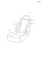
- FIG. 1 is a perspective view mainly showing an external shape of a vehicle seat used in a side airbag device according to the present invention, and an illustration of an airbag unit is omitted.
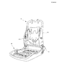
- FIG. 2 is a perspective view showing an internal structure (seat frame) that functions as a framework of the vehicle seat shown in FIG. 1, and the airbag unit is not shown.
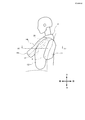
- FIG. 3 is a schematic side view of the side airbag device according to the first embodiment of the present invention, showing a state in which the airbag is deployed and observed from the outside (door trim side) in the vehicle width direction.
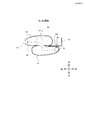
- FIG. 4 is a schematic view showing a deployed state of the airbag device according to the first embodiment of the present invention, and corresponds to a cross section taken along the line A1-A1 of FIG. FIG.
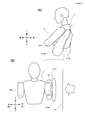
- FIG. 5 is a side view (A) and a front view (B) showing a deployed state (initial stage of deployment) of the airbag apparatus according to the first embodiment of the present invention.
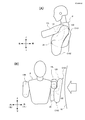
- FIG. 6 is a side view (A) and a front view (B) showing a deployed state (full deployment) of the airbag device according to the first embodiment of the present invention.
- FIG. 7 is a schematic view showing a deployed state of the airbag device according to the second embodiment of the present invention, and corresponds to a cross section taken along the line AA of FIG.
- FIG. 8 is a schematic side view of the side airbag device according to the third embodiment of the present invention, showing a state in which the airbag is deployed, as observed from the outside (door trim side) in the vehicle width direction.
- FIG. 9 is a schematic view showing a deployed state of the airbag device according to the third embodiment of the present invention, and corresponds to a cross section taken along line A3-A3 of FIG.
- FIG. 10 is a side view schematically showing the shape of the airbag (deployed state) according to the third embodiment of the present invention, in which (A) is a state seen from the door side in the vehicle width direction, and (B) is It is as seen from the passenger side.
- 11A and 11B are perspective side views showing the panel structure of the airbag according to the third embodiment of the present invention.
- FIG. 11A is a state as viewed from the door side in the vehicle width direction, and FIG. This is how it looks.
- FIG. 11A is a state as viewed from the door side in the vehicle width direction, and FIG. This is how it looks.
- FIG. 12 is a plan view showing a panel structure of an airbag according to a third embodiment of the present invention, showing a pair of left and right panels forming a second bag.
- FIG. 13 is a plan view showing a panel structure of an airbag according to a third embodiment of the present invention.
- (A) and (B) are a pair of left and right reinforcing panels provided inside the first bag, (B) ) Shows the panel that partitions the chambers in front of and behind the second bag.
- FIG. 14 is a plan view showing a panel structure of an airbag according to a third embodiment of the present invention.
- (A) and (B) are a pair of left and right panels constituting the first bag, and (B) is a first panel.
- FIG. 15 is a side view (A) and a front view (B) showing a deployed state (initial stage of deployment) of the airbag device according to the third embodiment of the present invention.
- FIG. 16 is a side view (A) and a front view (B) showing a deployed state (full deployment) of the airbag device according to the third embodiment of the present invention.
- the side airbag device is designed on the basis of an experimental dummy that assumes the occupant P.
- the present invention is not limited to designing to a specific experimental dummy, but in the present embodiment, as an example, when the experimental dummy is based on WSID (World Side Impact Impact Dummy). Will be described.
- FIG. 1 is a perspective view mainly showing the external shape of a vehicle seat used in a side airbag device according to a first embodiment of the present invention, and the airbag device is not shown.
- FIG. 2 is a perspective view showing an internal structure (seat frame) that functions as a framework of the vehicle seat shown in FIG. 1, and the illustration of the airbag device is also omitted here.
- the vehicle seat When viewed as a part, the vehicle seat according to the present embodiment, as shown in FIGS. 1 and 2, a seat cushion 2 at a portion on which an occupant sits; a seat back 1 that forms a backrest, and an upper end of the seat back 1. And a headrest 3 connected to the.
- a seat back frame 1f that forms the skeleton of the seat is provided inside the seat back 1, and a pad made of urethane foam or the like is provided on the surface and the periphery of the seat back frame 1f. Is covered by.
- a seating frame 2f is arranged on the bottom side of the seat cushion 2, and a pad made of urethane foam or the like is provided on the upper surface and the periphery thereof, and the surface of the pad is covered with a skin (not shown) such as leather or fabric. It is being appreciated.
- the seating frame 2f and the seatback frame 1f are connected via a reclining mechanism 4.
- the seatback frame 1f connects the left and right side frames 10 that extend apart in the vertical direction, the upper frame that connects the upper end of the side frame 10 and the lower end.
- the lower frame and the lower frame form a frame.
- the headrest 3 is configured by providing a cushion member on the outside of the headrest frame.
- FIG. 3 is a schematic side view of the side airbag device according to the present invention, showing a state in which the airbag is deployed, as observed from the outside (door trim side) in the vehicle width direction.
- FIG. 4 is a schematic view showing a deployed state of the airbag device according to the first embodiment of the present invention, and corresponds to a cross section taken along the line A1-A1 of FIG.
- the present invention is a side airbag device that is accommodated in the side support portion 5 of a vehicle seat, and includes airbags (C1 and C2) that restrain an occupant by inflating and deploying; and a side frame 10 inside the side support portion 5. And an inflator 30 for supplying inflation gas to the airbag (C1).
- the inflator 30 for example, a cylindrical cylinder type inflator can be used. From the outer peripheral portion of the inflator 30, a pair of upper and lower stud bolts 32 project inward in the vehicle width direction. These stud bolts 32 are attached (fastened and fixed) to the side frame 10 by nuts.
- the inflator 30 is formed with a plurality of gas ejection ports arranged in the circumferential direction, and gas is ejected radially from the gas ejection ports. A diffuser for controlling the gas flow can be provided if necessary.
- An airbag control ECU (not shown) mounted on the vehicle is electrically connected to the inflator 30.
- a satellite sensor that detects a side collision is electrically connected to the airbag control ECU. Then, the inflator 30 can be configured to be activated when the airbag control ECU detects a side collision based on a signal from the satellite sensor.
- the airbag (C1, C2) includes a first bag C1 having the inflator 30 housed therein; and a second bag C2 deployed inside the first bag C1 in the vehicle width direction. Is included.
- a first internal vent hole V1-2 is formed at a boundary portion between the first bag C1 and the second bag C2, and the second bag C2 is expanded by the inflation gas flowing from the first bag C1. It is like this.
- the flow of the inflation gas at the time of deploying the airbag flows from the first bag C1 to the second bag C2 via the vent hole V1-2, as shown by the dashed arrow, and then to the front end portion of the second bag C2.
- the air is exhausted from the external vent hole VF formed in the.
- an inclined portion that is inclined so that the front is lower than the rear is formed at the upper edge of the second bag C2. ..
- the front portion of the inclined portion is located below the centerline 14a extending in the longitudinal direction of the upper arm portion 14L of the occupant P seated on the vehicle seat, and enters the lower portion (armpit) of the occupant P's upper arm portion 14L.
- the protective region 22 is formed.
- the rear portion of the inclined portion of the second bag C2 is located above the centerline 14a extending in the longitudinal direction of the upper arm portion 14L of the occupant P seated on the vehicle seat, and the airbags (C1, C2) are deployed.
- a second protection region 20 for protecting the shoulder of the occupant P is sometimes formed. It should be noted that it is preferable to appropriately adjust the range and ratio of the first protection area 22 and the second protection area 20 to be formed, depending on the type of vehicle in which the airbag device is mounted, the shape of the seat, and the like. ..
- the side frame 10 is formed of resin or metal and can have an L-shaped cross section or a U-shaped cross section.
- the side frame 10 includes a frame side wall portion 10a extending along the vehicle traveling direction when the horizontal cross section is viewed from above. Then, as described above, the inflator 30 is fixed by the stud bolts 32 to the outside of the frame side wall portion 10a in the vehicle width direction.
- the capacity of the second bag C2 is set to be larger than that of the first bag C1.
- the first bag C1 is deployed so as to come into contact with the second bag C2 and the side structure (door trim or the like) 18 of the vehicle at an initial stage of deployment of the airbag. ..
- the first bag C1 is instantly expanded by the inflation gas output from the inflator 30, and the vehicle seat (side frame 10) and the side structure 18 are formed. You can quickly fill the gap.
- the first bag C1 is designed to be deployed so as to come into contact with the second bag C1 and the side structure (18) before the second bag C2 is completely deployed.
- the rear portion of the first bag C1 when viewed from the side of the vehicle has a frame side wall 1 0a is arranged so that the frame side wall 10a serves as a reaction surface to quickly and surely deploy outward in the vehicle width direction.
- FIG. 5 and 6 are a side view (A) and a front view (B) showing a deployed state of the airbag device according to the present invention, FIG. 5 showing an initial stage of deployment, and FIG. 6 showing a fully deployed state. Show.
- the inflation gas released from the inflator 30 flows into the first bag C1 and the second bag C2.
- the first bag C1 is fully deployed first, but the second bag C2 is partially deployed.
- the first bag C1 is deployed so as to fill the gap between the second bag C2 and the door trim 18. Therefore, the pressure of the door trim 18 can be reliably and promptly transmitted to the second bag C2 via the first bag C1 located in the middle.
- the second bag C2 is fully deployed and is pushed into the passenger side through the first bag C1 as shown in FIG. It will be.
- the first protection area 22 of the second bag C2 is located below the upper arm 14L of the occupant P, the first protective area 22 slips under the upper arm 14L of the occupant P (armpit) to slide the upper arm 14L upward. Lift to. As a result, the upper arm 14L is not sandwiched between the airbag (C1, C2) and the chest of the occupant P, and it is possible to avoid a situation in which the chest of the occupant P is pressed by excessive pressure.
- the second protection area 20 of the second bag C2 since the second protection area 20 of the second bag C2 is located above the upper arm 14L of the occupant P, it does not enter under the upper arm 14L and protects the vicinity of the shoulder as it is.
- FIG. 7 is a schematic view showing a deployed state of the airbag device according to the second embodiment of the present invention, and corresponds to the cross section taken along the line A1-A1 of FIG.
- the difference between this embodiment and the first embodiment shown in FIG. 4 is the structure of the second bag C2. That is, in this embodiment, the second bag C2 is divided into the front and the rear to form the front chamber portion C2F and the rear chamber portion C2R.
- a partition panel 40 is arranged at the boundary between the front chamber portion C2F and the rear chamber portion C2R, and a vent hole V2 is formed in a part thereof.
- the inflation gas flowing out of the first bag C1 flows into the rear chamber portion C2R of the second bag C2, and then flows into the front chamber portion C2F via the vent hole V2. ..
- the front chamber portion C2F mainly forms the first protection region 22, and the rear chamber portion C2R mainly forms the second protection region 20.
- the rear chamber portion C2R of the second bag C2 is deployed first, so that the shoulder portion of the occupant P can be quickly protected at the initial stage of airbag deployment, and the lateral direction of the occupant can be reduced. The movement of can be restrained promptly.
- the front chamber portion C2F is deployed after the rear chamber portion C2R, the first protection region 22 does not cause the occupant's upper arm portion 14L to suddenly jump up, and at a relatively gentle timing. It is possible to lift the upper arm portion 14 of the occupant P.
- FIG. 8 is a schematic side view of the side airbag device according to the third embodiment of the present invention, showing a state in which the airbag is deployed, as observed from the outside (door trim side) in the vehicle width direction.
- FIG. 9 is a schematic view showing a deployed state of the airbag device according to the third embodiment of the present invention, and corresponds to a cross section taken along line A3-A3 of FIG.
- the side airbag device includes an airbag (C101, C102) that restrains an occupant by inflating and deploying the airbag; And an inflator 30 for supplying inflation gas to the bag (C101).
- the inflator 30 for example, a cylindrical cylinder type inflator can be used. From the outer peripheral portion of the inflator 30, a pair of upper and lower stud bolts 32 project inward in the vehicle width direction. These stud bolts 32 are attached (fastened and fixed) to the side frame 10 by nuts.
- the inflator 30 is formed with a plurality of gas ejection ports arranged in the circumferential direction, and gas is ejected radially from the gas ejection ports. A diffuser for controlling the gas flow can be provided if necessary.
- An airbag control ECU (not shown) mounted on the vehicle is electrically connected to the inflator 30.
- a satellite sensor that detects a side collision is electrically connected to the airbag control ECU. Then, the inflator 30 can be configured to be activated when the airbag control ECU detects a side collision based on a signal from the satellite sensor.
- an inclined portion that is inclined so that the front is lower than the rear is formed at the upper edge of the second bag C102.
- the front portion of the inclined portion is located below the centerline 14a extending in the longitudinal direction of the upper arm portion 14L of the occupant P seated on the vehicle seat, and enters the lower portion (armpit) of the occupant P's upper arm portion 14L.
- the rear portion of the inclined portion of the second bag C102 is located above the centerline 14a extending in the longitudinal direction of the upper arm portion 14L of the occupant P seated on the vehicle seat, and the shoulder of the occupant P when the airbag is deployed.
- a second protection region 120 for protecting the portion is formed. It should be noted that it is preferable to appropriately adjust the range and the ratio of the first protection area 122 and the second protection area 120 to be formed, depending on the type of vehicle in which the airbag device is mounted, the shape of the seat, and the like. ..
- the airbag (C101, C102) includes a first bag C101 containing the inflator 30 therein; and a second bag C102 deployed outside the first bag C101 in the vehicle width direction. Is included.
- a first internal vent hole V1-2 is formed at the boundary between the first bag C101 and the second bag C102, and the second bag C102 is expanded by the inflation gas flowing from the first bag C101. It is like this.
- the flow of the inflation gas when the airbag is deployed flows from the first bag C101 through the vent hole V1-2 to the second bag C102 as shown by the dashed arrow, and then the front end portion of the second bag C102.
- the air is exhausted from the external vent hole VF formed in the.
- the second bag C102 is divided into front and rear parts to form a front chamber part C102F and a rear chamber part C102R.
- a partition panel 140 is arranged at the boundary between the front chamber portion C102F and the rear chamber portion C102R, and two vent holes V2 (V2a, V2b) are formed in a part of the partition panel 140.
- the inflation gas flowing out of the first bag C101 flows into the rear chamber portion C102R of the second bag C102, and then flows into the front chamber portion C102F via the vent hole V2. ..
- the front chamber portion C102F mainly forms the first protection region 122
- the rear chamber portion C102R mainly forms the second protection region 120.
- the rear chamber portion C102R of the second bag C102 is deployed first, so that the shoulder portion of the occupant P can be quickly protected in the initial stage of airbag deployment, and the occupant's lateral direction can be reduced. The movement of can be restrained promptly.
- the front chamber portion C102F is deployed after the rear chamber portion C102R, the first protection area 122 does not cause the occupant's upper arm portion 14L to suddenly jump up, and at a relatively gentle timing. It is possible to lift the upper arm portion 14L of the occupant P.
- the capacity of the second bag C102 is set to be larger than that of the first bag C101. Further, as will be described in detail later, the first bag C101 is deployed so as to enter the armpit of the occupant P or the upper arm 14L at the initial stage of deployment of the airbag.
- the capacity of the first bag C101 is reduced by reducing the capacity of the first bag C101, it is possible to instantly deploy the first bag C101 due to the inflation gas output from the inflator 30, and to create an opportunity to quickly lift the occupant's upper arm 14L. Becomes That is, the upper bag 14L of the occupant P is slightly lifted by the first bag C101, and then the second bag C102 is easily inserted under the upper arm 14L.
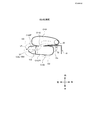
- FIG. 10 is a side view schematically showing the configuration of an airbag (deployed state) according to the third embodiment of the present invention, in which (A) is a state seen from the door side in the vehicle width direction, and (B) is It is as seen from the passenger side.
- the first bag C101 in the present embodiment is deployed on the occupant side (inner side), and has a boot-like shape in which the lower portion projects forward as shown in FIG.
- the protruding lower portion 101a of the first bag C101 is preferably positioned near the waist of the occupant P when the airbag is deployed.
- FIGS. 12 to 14 are perspective side views showing the panel structure of the airbag according to the third embodiment of the present invention.
- FIG. 11A is a state seen from the door side in the vehicle width direction
- FIG. 11B is seen from the passenger side. This is how it looks. Note that in FIG. 11, all the panels shown in FIGS. 12 to 14 are shown.
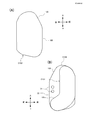
- FIG. 12 is a plan view showing a panel structure of an airbag according to a third embodiment of the present invention, showing a pair of left and right panels forming a second bag C102.
- the second bag C102 is formed into a bag shape by sewing the outer edges of the left and right main panels 102a and 102b.
- vent holes 122a, 122b, 122c connected to the first bag C101 are formed in the main panel 102b located on the occupant side (inner side, first bag C101 side).
- holes 120a and 120b that form vent holes VF are formed on the front edge side of the main panel 102b.
- FIG. 13 is a plan view showing a panel structure of an airbag according to a third embodiment of the present invention, in which (A) and (B) are a pair of left and right reinforcing panels 130a provided inside the second bag C102, 130b and (B) show the panel 140 that partitions the chambers in front and behind the second bag C102.
- the reinforcing panels 130a and 130b are fixed to the insides of the main panels 102a and 102b (FIG. 12) by sewing, and the reinforcing panels 130b located on the occupant side (inside, the first bag C101 side) include: Holes 134a and 134b are formed at positions corresponding to the holes 120a and 120b of the main panel 102b.
- vent holes 136a, 136b, 136c connected to the first bag C101 are formed in the reinforcing panel 130b located on the occupant side (inner side, first bag C101 side). These vent holes 136a, 136b, 136c are adapted to overlap with the vent holes 122a, 122b, 122c formed in the main panel 102b.
- the partition panel 140 is formed in a band shape, and is sewn inside the reinforcing panels 130a and 130b in a state where the lower portion is bent so as to project toward the front.
- Inner vents V2a and V2b are formed on the partition panel 140 at upper and lower two locations so that gas flows from the rear chamber portion C102R of the second bag C102 to the front chamber portion C102F.
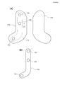
- FIG. 14 is a plan view showing a panel structure of an airbag according to a third embodiment of the present invention, in which (A) and (B) are a pair of left and right sub-panels 110a, 110b, which constitute the first bag C101. B) is a reinforcing panel 110c sewn between the first bag C101 and the second bag C102.
- the outer panel 110a is arranged on the second bag C102 side (outer side), and the inner panel 110b is arranged on the occupant P side.
- the outer edges of the panels 110a and 110b are sewn to form a bag.
- the sub-panels 110a and 110b have the same symmetrical shape and have a boot-like shape with the lower part protruding forward when deployed (FIG. 9).
- the outer panel 110a is formed with three inner vents 120a, 120b, 120c communicating with the second bag C102. Further, holes 122a, 122b, 122c are also formed at corresponding portions of the reinforcing panel 110c.
- vent holes 122a, 122b, 122c (FIG. 12) of the panel 102b constituting the second bag C102, the vent holes 136a, 136b, 136c (FIG. 13) formed in the reinforcing panel 130b, and the first bag
- the vent holes 120a, 120b, 120c (FIG. 14(A)) of the panel 110a constituting the C101 and the vent holes 122a, 122b, 122c of the reinforcing panel 110c are overlapped with each other in a corresponding state, and the periphery thereof is sewn. This is the case (FIG. 11(B)).
- the inflation gas flows from the first bag C101 into the second bag C102.
- the diffuser panels 200a and 200b can be provided inside the second bag C102 as shown in FIG. These diffuser panels 200a and 200b can be configured to guide the flow of gas released from the inflator 30 in the vertical direction, for example.
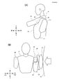
- 15 and 16 are a side view (A) and a front view (B) showing a deployed state of the airbag apparatus according to the present embodiment.
- FIG. 15 is an initial stage of deployment
- FIG. 16 is a fully deployed state. Indicates.
- the inflation gas released from the inflator 30 flows into the first bag C101 and the second bag C102.
- the first bag C101 is fully deployed first, but the second bag C102 is partially deployed.
- the first bag C101 enters under the upper arm 14L of the occupant P and lifts the upper arm 14 of the occupant.
- the lower portion 101a of the first bag C101 comes into contact with the occupant's elbow (the lower part of the upper arm) to lift the upper arm 14L.
- the first protection area 122 of the second bag 102C slips under the upper arm 14L of the occupant P (armpit), and lifts the upper arm 14L further upward.
- the upper arm 14L is not sandwiched between the airbag (C101, C102) and the chest of the occupant P, and it is possible to avoid a situation in which the chest of the occupant P is pressed by excessive pressure.
- the second protection area 120 of the second bag C102 is located above the upper arm 14L of the occupant P, it does not enter under the upper arm 14L and protects the vicinity of the shoulder as it is.
- the first bag C101 can be instantly deployed, and an opportunity to quickly lift the occupant's upper arm 14L can be created. That is, the upper arm 14L of the occupant P can be slightly lifted by the first bag C101, and the second bag C102 can smoothly enter (dive into) below the upper arm 14L and can be lifted further.
- the first bag C101 has the lower portion 101a protruding forward, but it does not necessarily have to have a region having such a shape.
- the upper portion of the first bag C1 is placed under the armpit of the occupant P (upper arm). It is also possible to adopt a configuration in which it enters into the vicinity of the root), and by this, it is possible to obtain the same effect as in the third embodiment.
Landscapes
- Engineering & Computer Science (AREA)
- Mechanical Engineering (AREA)
- Air Bags (AREA)
Abstract
Priority Applications (3)
| Application Number | Priority Date | Filing Date | Title |
|---|---|---|---|
| US17/310,462 US11752966B2 (en) | 2019-02-09 | 2019-12-23 | Side airbag device |
| EP19914541.8A EP3922517B1 (fr) | 2019-02-09 | 2019-12-23 | Dispositif de coussin de sécurité gonflable latéral |
| JP2020571035A JP7100163B2 (ja) | 2019-02-09 | 2019-12-23 | サイドエアバッグ装置 |
Applications Claiming Priority (4)
| Application Number | Priority Date | Filing Date | Title |
|---|---|---|---|
| JP2019022181 | 2019-02-09 | ||
| JP2019-022181 | 2019-02-09 | ||
| JP2019-137328 | 2019-07-25 | ||
| JP2019137328 | 2019-07-25 |
Publications (1)
| Publication Number | Publication Date |
|---|---|
| WO2020162065A1 true WO2020162065A1 (fr) | 2020-08-13 |
Family
ID=71948180
Family Applications (1)
| Application Number | Title | Priority Date | Filing Date |
|---|---|---|---|
| PCT/JP2019/050446 Ceased WO2020162065A1 (fr) | 2019-02-09 | 2019-12-23 | Dispositif de coussin de sécurité gonflable latéral |
Country Status (4)
| Country | Link |
|---|---|
| US (1) | US11752966B2 (fr) |
| EP (1) | EP3922517B1 (fr) |
| JP (1) | JP7100163B2 (fr) |
| WO (1) | WO2020162065A1 (fr) |
Cited By (4)
| Publication number | Priority date | Publication date | Assignee | Title |
|---|---|---|---|---|
| JP2021169227A (ja) * | 2020-04-13 | 2021-10-28 | 株式会社Subaru | 乗員保護システム |
| US11214225B2 (en) * | 2017-08-01 | 2022-01-04 | Autoliv Development Ab | Passenger protection apparatus |
| JP2022133976A (ja) * | 2021-03-02 | 2022-09-14 | 本田技研工業株式会社 | サイドエアバッグ装置 |
| WO2025013523A1 (fr) * | 2023-07-10 | 2025-01-16 | オートリブ ディベロップメント エービー | Dispositif de coussin de sécurité gonflable latéral pour véhicule |
Families Citing this family (4)
| Publication number | Priority date | Publication date | Assignee | Title |
|---|---|---|---|---|
| KR102731808B1 (ko) * | 2019-09-27 | 2024-11-19 | 현대모비스 주식회사 | 사이드 에어백 장치의 폴딩 방법 및 사이드 에어백 장치 |
| KR102729838B1 (ko) * | 2020-02-16 | 2024-11-14 | 아우토리브 디벨롭먼트 아베 | 에어백 장치 및 차량용 시트 |
| US12122316B2 (en) * | 2020-10-13 | 2024-10-22 | Autoliv Development Ab | Side airbag device |
| CN116872879A (zh) * | 2023-07-07 | 2023-10-13 | 浙江吉利控股集团有限公司 | 安全气囊、车辆座椅和车辆 |
Citations (11)
| Publication number | Priority date | Publication date | Assignee | Title |
|---|---|---|---|---|
| JP2009023494A (ja) | 2007-07-19 | 2009-02-05 | Toyoda Gosei Co Ltd | サイドエアバッグ装置 |
| JP2010132072A (ja) * | 2008-12-03 | 2010-06-17 | Toyota Motor Corp | 車両用サイドエアバッグ装置 |
| JP2011051414A (ja) * | 2009-08-31 | 2011-03-17 | Autoliv Development Ab | サイドエアバッグ装置 |
| JP2012179956A (ja) * | 2011-02-28 | 2012-09-20 | Fuji Heavy Ind Ltd | 乗員保護装置及び乗員保護方法 |
| JP2013147119A (ja) * | 2012-01-18 | 2013-08-01 | Autoliv Development Ab | サイドエアバッグ |
| JP2013147041A (ja) * | 2012-01-17 | 2013-08-01 | Toyota Motor Corp | 車両用サイドエアバッグ装置 |
| JP2013154786A (ja) * | 2012-01-30 | 2013-08-15 | Toyota Motor Corp | 車両用サイドエアバッグ装置 |
| JP2013216211A (ja) * | 2012-04-09 | 2013-10-24 | Ashimori Industry Co Ltd | サイドエアバッグ装置 |
| WO2015036116A1 (fr) * | 2013-09-13 | 2015-03-19 | Trw Automotive Gmbh | Procédé de protection d'un occupant de véhicule et sac gonflable |
| JP2017197017A (ja) * | 2016-04-27 | 2017-11-02 | マツダ株式会社 | サイドエアバッグ装置 |
| WO2017209192A1 (fr) * | 2016-06-01 | 2017-12-07 | オートリブ ディベロップメント エービー | Dispositif de protection d'occupants |
Family Cites Families (16)
| Publication number | Priority date | Publication date | Assignee | Title |
|---|---|---|---|---|
| JP2008201172A (ja) * | 2007-02-16 | 2008-09-04 | Toyota Motor Corp | サイドエアバッグ装置。 |
| JP5594340B2 (ja) * | 2012-09-05 | 2014-09-24 | トヨタ自動車株式会社 | 車両用安全装置 |
| JP2014076702A (ja) * | 2012-10-09 | 2014-05-01 | Toyota Motor Corp | 車両用乗員保護装置 |
| JP5895872B2 (ja) * | 2013-02-26 | 2016-03-30 | トヨタ自動車株式会社 | 車両用サイドエアバッグ装置 |
| JP5761231B2 (ja) * | 2013-02-26 | 2015-08-12 | トヨタ自動車株式会社 | 車両用サイドエアバッグ装置 |
| US9139153B2 (en) * | 2013-09-05 | 2015-09-22 | Ford Global Technologies, Llc | Vehicle side impact airbag with laterally extending thoracic chamber |
| WO2016158022A1 (fr) * | 2015-03-30 | 2016-10-06 | オートリブ ディベロップメント エービー | Dispositif d'airbag latéral pour véhicule |
| WO2017010169A1 (fr) * | 2015-07-11 | 2017-01-19 | オートリブ ディベロップメント エービー | Dispositif de protection d'occupant de véhicule |
| JP6561942B2 (ja) * | 2016-08-22 | 2019-08-21 | トヨタ自動車株式会社 | サイドエアバッグ装置を搭載した車両用シート |
| US11235724B2 (en) * | 2017-03-30 | 2022-02-01 | Autoliv Development Ab | Passenger protection apparatus |
| KR102387636B1 (ko) * | 2017-08-01 | 2022-04-18 | 아우토리브 디벨롭먼트 아베 | 승차인 보호 장치 |
| JP6848762B2 (ja) * | 2017-08-09 | 2021-03-24 | トヨタ自動車株式会社 | サイドエアバッグ装置 |
| JP6856482B2 (ja) * | 2017-09-20 | 2021-04-07 | トヨタ自動車株式会社 | サイドエアバッグ装置を搭載した車両用シート及びサイドエアバッグ装置 |
| KR102535016B1 (ko) * | 2018-06-19 | 2023-05-23 | 아우토리브 디벨롭먼트 아베 | 사이드 에어백 장치 및 이것을 구비한 차량용 시트 |
| US11414036B2 (en) * | 2020-03-05 | 2022-08-16 | Honda Motor Co., Ltd. | Torso stabilization restraint |
| JP7564735B2 (ja) * | 2021-03-02 | 2024-10-09 | 本田技研工業株式会社 | サイドエアバッグ装置 |
-
2019
- 2019-12-23 JP JP2020571035A patent/JP7100163B2/ja active Active
- 2019-12-23 EP EP19914541.8A patent/EP3922517B1/fr active Active
- 2019-12-23 WO PCT/JP2019/050446 patent/WO2020162065A1/fr not_active Ceased
- 2019-12-23 US US17/310,462 patent/US11752966B2/en active Active
Patent Citations (11)
| Publication number | Priority date | Publication date | Assignee | Title |
|---|---|---|---|---|
| JP2009023494A (ja) | 2007-07-19 | 2009-02-05 | Toyoda Gosei Co Ltd | サイドエアバッグ装置 |
| JP2010132072A (ja) * | 2008-12-03 | 2010-06-17 | Toyota Motor Corp | 車両用サイドエアバッグ装置 |
| JP2011051414A (ja) * | 2009-08-31 | 2011-03-17 | Autoliv Development Ab | サイドエアバッグ装置 |
| JP2012179956A (ja) * | 2011-02-28 | 2012-09-20 | Fuji Heavy Ind Ltd | 乗員保護装置及び乗員保護方法 |
| JP2013147041A (ja) * | 2012-01-17 | 2013-08-01 | Toyota Motor Corp | 車両用サイドエアバッグ装置 |
| JP2013147119A (ja) * | 2012-01-18 | 2013-08-01 | Autoliv Development Ab | サイドエアバッグ |
| JP2013154786A (ja) * | 2012-01-30 | 2013-08-15 | Toyota Motor Corp | 車両用サイドエアバッグ装置 |
| JP2013216211A (ja) * | 2012-04-09 | 2013-10-24 | Ashimori Industry Co Ltd | サイドエアバッグ装置 |
| WO2015036116A1 (fr) * | 2013-09-13 | 2015-03-19 | Trw Automotive Gmbh | Procédé de protection d'un occupant de véhicule et sac gonflable |
| JP2017197017A (ja) * | 2016-04-27 | 2017-11-02 | マツダ株式会社 | サイドエアバッグ装置 |
| WO2017209192A1 (fr) * | 2016-06-01 | 2017-12-07 | オートリブ ディベロップメント エービー | Dispositif de protection d'occupants |
Non-Patent Citations (1)
| Title |
|---|
| See also references of EP3922517A4 |
Cited By (6)
| Publication number | Priority date | Publication date | Assignee | Title |
|---|---|---|---|---|
| US11214225B2 (en) * | 2017-08-01 | 2022-01-04 | Autoliv Development Ab | Passenger protection apparatus |
| JP2021169227A (ja) * | 2020-04-13 | 2021-10-28 | 株式会社Subaru | 乗員保護システム |
| JP7416659B2 (ja) | 2020-04-13 | 2024-01-17 | 株式会社Subaru | 乗員保護システム |
| JP2022133976A (ja) * | 2021-03-02 | 2022-09-14 | 本田技研工業株式会社 | サイドエアバッグ装置 |
| JP7564734B2 (ja) | 2021-03-02 | 2024-10-09 | 本田技研工業株式会社 | サイドエアバッグ装置 |
| WO2025013523A1 (fr) * | 2023-07-10 | 2025-01-16 | オートリブ ディベロップメント エービー | Dispositif de coussin de sécurité gonflable latéral pour véhicule |
Also Published As
| Publication number | Publication date |
|---|---|
| EP3922517A1 (fr) | 2021-12-15 |
| EP3922517A4 (fr) | 2022-12-14 |
| JP7100163B2 (ja) | 2022-07-12 |
| US11752966B2 (en) | 2023-09-12 |
| EP3922517B1 (fr) | 2026-02-18 |
| JPWO2020162065A1 (ja) | 2021-10-07 |
| US20220126779A1 (en) | 2022-04-28 |
Similar Documents
| Publication | Publication Date | Title |
|---|---|---|
| JP7100163B2 (ja) | サイドエアバッグ装置 | |
| CN107848483B (zh) | 驾乘人员保护装置 | |
| JP4758455B2 (ja) | 乗員保護装置 | |
| JP5648754B2 (ja) | 車両用シート | |
| CN114174128B (zh) | 安全气囊装置 | |
| CN107640119B (zh) | 车辆乘员约束装置 | |
| US11752965B2 (en) | Side airbag device and method for manufacturing side airbag device | |
| KR20220065016A (ko) | 에어백 장치 및 차량용 시트 | |
| JP6748294B2 (ja) | 乗員保護装置 | |
| CN111615473B (zh) | 乘员保护装置 | |
| JP2017222331A (ja) | 車両用エアバッグ装置及び車両用乗員拘束装置 | |
| CN110869248A (zh) | 乘员保护装置 | |
| CN103958264B (zh) | 车辆用座椅 | |
| JP6365589B2 (ja) | 車両用乗員保護装置 | |
| JP2011143805A (ja) | エアバッグ装置 | |
| CN115003560B (zh) | 安全气囊装置以及车辆用座椅 | |
| CN109795440B (zh) | 车辆用侧气囊装置 | |
| JP7381772B2 (ja) | シート内蔵エアバッグ装置 | |
| KR20220076487A (ko) | 사이드 에어백 장치 및 이것에 사용되는 에어백의 제조 방법 | |
| JP7314107B2 (ja) | サイドエアバッグ装置 | |
| JP7519393B2 (ja) | シート内蔵エアバッグ装置 | |
| JP2020059334A (ja) | 車両用シート | |
| WO2022209259A1 (fr) | Dispositif de coussin de sécurité gonflable latéral et son procédé de fabrication | |
| JP2025006656A (ja) | 車両用ファーサイドエアバッグ装置 | |
| WO2022009757A1 (fr) | Dispositif de coussin de sécurité gonflable |
Legal Events
| Date | Code | Title | Description |
|---|---|---|---|
| 121 | Ep: the epo has been informed by wipo that ep was designated in this application |
Ref document number: 19914541 Country of ref document: EP Kind code of ref document: A1 |
|
| ENP | Entry into the national phase |
Ref document number: 2020571035 Country of ref document: JP Kind code of ref document: A |
|
| NENP | Non-entry into the national phase |
Ref country code: DE |
|
| ENP | Entry into the national phase |
Ref document number: 2019914541 Country of ref document: EP Effective date: 20210909 |
|
| WWG | Wipo information: grant in national office |
Ref document number: 2019914541 Country of ref document: EP |