WO2020170422A1 - Stator, moteur et compresseur - Google Patents
Stator, moteur et compresseur Download PDFInfo
- Publication number
- WO2020170422A1 WO2020170422A1 PCT/JP2019/006783 JP2019006783W WO2020170422A1 WO 2020170422 A1 WO2020170422 A1 WO 2020170422A1 JP 2019006783 W JP2019006783 W JP 2019006783W WO 2020170422 A1 WO2020170422 A1 WO 2020170422A1
- Authority
- WO
- WIPO (PCT)
- Prior art keywords
- coil
- peripheral side
- stator
- winding
- coils
- Prior art date
- Legal status (The legal status is an assumption and is not a legal conclusion. Google has not performed a legal analysis and makes no representation as to the accuracy of the status listed.)
- Ceased
Links
Images











Classifications
-
- H—ELECTRICITY
- H02—GENERATION; CONVERSION OR DISTRIBUTION OF ELECTRIC POWER
- H02K—DYNAMO-ELECTRIC MACHINES
- H02K1/00—Details of the magnetic circuit
- H02K1/06—Details of the magnetic circuit characterised by the shape, form or construction
-
- H—ELECTRICITY
- H02—GENERATION; CONVERSION OR DISTRIBUTION OF ELECTRIC POWER
- H02K—DYNAMO-ELECTRIC MACHINES
- H02K1/00—Details of the magnetic circuit
- H02K1/06—Details of the magnetic circuit characterised by the shape, form or construction
- H02K1/12—Stationary parts of the magnetic circuit
-
- H—ELECTRICITY
- H02—GENERATION; CONVERSION OR DISTRIBUTION OF ELECTRIC POWER
- H02K—DYNAMO-ELECTRIC MACHINES
- H02K3/00—Details of windings
-
- H—ELECTRICITY
- H02—GENERATION; CONVERSION OR DISTRIBUTION OF ELECTRIC POWER
- H02K—DYNAMO-ELECTRIC MACHINES
- H02K3/00—Details of windings
- H02K3/04—Windings characterised by the conductor shape, form or construction, e.g. with bar conductors
-
- H—ELECTRICITY
- H02—GENERATION; CONVERSION OR DISTRIBUTION OF ELECTRIC POWER
- H02K—DYNAMO-ELECTRIC MACHINES
- H02K3/00—Details of windings
- H02K3/04—Windings characterised by the conductor shape, form or construction, e.g. with bar conductors
- H02K3/12—Windings characterised by the conductor shape, form or construction, e.g. with bar conductors arranged in slots
-
- H—ELECTRICITY
- H02—GENERATION; CONVERSION OR DISTRIBUTION OF ELECTRIC POWER
- H02K—DYNAMO-ELECTRIC MACHINES
- H02K3/00—Details of windings
- H02K3/46—Fastening of windings on the stator or rotor structure
-
- H—ELECTRICITY
- H02—GENERATION; CONVERSION OR DISTRIBUTION OF ELECTRIC POWER
- H02K—DYNAMO-ELECTRIC MACHINES
- H02K3/00—Details of windings
- H02K3/46—Fastening of windings on the stator or rotor structure
- H02K3/48—Fastening of windings on the stator or rotor structure in slots
-
- H—ELECTRICITY
- H02—GENERATION; CONVERSION OR DISTRIBUTION OF ELECTRIC POWER
- H02K—DYNAMO-ELECTRIC MACHINES
- H02K3/00—Details of windings
- H02K3/46—Fastening of windings on the stator or rotor structure
- H02K3/50—Fastening of winding heads, equalising connectors, or connections thereto
Definitions
- the present invention relates to a stator having distributed windings, an electric motor equipped with the stator, and a compressor equipped with the electric motor.
- the compressor used in the refrigeration cycle device is equipped with an electric motor such as a synchronous electric motor.
- the electric motor includes a hollow-cylindrical stator around which a winding is wound, and a rotor arranged on the inner peripheral side of the stator.
- Concentrated winding is often used for winding the windings of the stator of such an electric motor (see Patent Document 1). This is because the concentrated winding can reduce the coil end and the winding resistance as compared with the distributed winding.
- the distributed winding may be more advantageous than the concentrated winding. This is because the distributed winding has a higher winding coefficient than the concentrated winding, and the magnetic flux of the rotor can be effectively used. Therefore, a stator having distributed windings is often used in a compressor electric motor that requires a large capacity.
- motors such as synchronous motors and induction motors are required to be small and have high performance. Therefore, in order to miniaturize a high-performance electric motor having a stator having distributed windings, for example, a wave winding in which a coil is formed by winding a winding on a stator core without forming a loop.
- a method has been proposed in which one coil forming the same phase is arranged in one slot to reduce the coil circumferential length and the winding resistance value.
- the electric motor using the wave winding for the stator had a problem that the reliability was lowered.
- the winding is wound in an annular shape to form an annular coil.
- a plurality of locations on the outer peripheral portion of this annular coil are pushed toward the inner peripheral side to form a star-shaped coil having an uneven shape.
- An external force applied to the winding of the wave winding at the time of forming the star coil may damage the insulating coating of the winding to lower the insulation performance and reduce the reliability.
- the present invention has been made to solve the above problems, and it is an object of the present invention to obtain a stator that can achieve miniaturization and high performance of an electric motor and can suppress deterioration of reliability of the electric motor.
- a second object of the present invention is to obtain an electric motor and a compressor provided with such a stator.
- the stator according to the present invention has a hollow cylindrical shape, and a plurality of slots on the inner peripheral side are arranged at regular intervals in the circumferential direction, and a stator core, and a distribution wound through the slots.
- Windings of concentric windings, the number of slots for each pole is 1 for each phase, the windings of the same phase have the same number of coils as the number of poles, and half of these coils are on the outer peripheral side. It is a coil and is arranged on the outer peripheral side with respect to the inner peripheral side coil which is the other half of these coils, and the outer peripheral side coil and the inner peripheral side coil are arranged alternately in the circumferential direction.
- the electric motor according to the present invention includes the stator according to the present invention and a rotor arranged on the inner peripheral side of the stator.
- the compressor according to the present invention includes the electric motor according to the present invention and a compression mechanism that compresses the refrigerant by the driving force of the electric motor.
- the stator according to the present invention includes distributed windings. Further, by arranging the coils of the windings of the same phase as in the stator according to the present invention, the coil end can be downsized and the resistance value of the windings can be reduced. Therefore, by using the stator according to the present invention, it is possible to reduce the size and performance of the electric motor.
- the windings of the stator according to the present invention are concentric. When forming the concentric winding, the external force applied when forming the star coil of the wave winding is unnecessary. Therefore, by using the stator according to the present invention, it is possible to suppress the deterioration of the reliability of the electric motor.
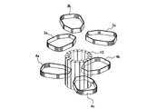
- FIG. 3 is a perspective view showing an outer peripheral side coil of a U-phase winding in the stator according to the first embodiment of the present invention.
- FIG. 3 is a perspective view showing an inner circumference side coil of a U-phase winding in the stator according to the first embodiment of the present invention.
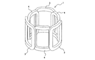
- FIG. 3 is a perspective view showing an outer peripheral side coil and an inner peripheral side coil of the U-phase winding in the stator according to the first embodiment of the present invention.
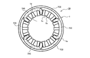
- FIG. 3 is a plan view for explaining the stator according to the first embodiment of the present invention, and is a perspective view showing a stator core and a U-phase winding.
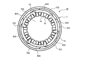
- FIG. 3 is a plan view for explaining the stator according to the first embodiment of the present invention, and is a perspective view showing a stator core, a U-phase winding, and a V-phase winding.
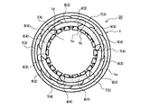
- FIG. 3 is a plan view for explaining the stator according to the first embodiment of the present invention, and is a perspective view showing a stator core, a U-phase winding, a V-phase winding, and a W-phase winding.
- FIG. 6 is a perspective view for explaining a step of inserting the U-phase winding into the slot of the stator core of the stator according to the first embodiment of the present invention.
- FIG. 6 is a perspective view for explaining a step of inserting the U-phase winding into the slot of the stator core of the stator according to the first embodiment of the present invention.
- FIG. 6 is a perspective view for explaining a step of inserting the U-phase winding into the slot of the stator core of the stator according to the first embodiment of the present invention.
- FIG. 11 is a perspective view for explaining an example of a stator according to a third embodiment of the present invention, and is a perspective view showing a stator core and a part of a winding wire. It is a perspective view for explaining the process of winding and forming the U-phase winding of the stator concerning Embodiment 3 of the present invention. It is a perspective view for explaining the process of winding and forming the U-phase winding of the stator concerning Embodiment 3 of the present invention.
- FIG. 14 is a perspective view for explaining another example of the stator according to the third embodiment of the present invention, and is a perspective view showing a stator core and a U-phase winding.
- FIG. 21 is a perspective view for explaining a process of winding the U-phase winding of the stator shown in FIG. 20.
- FIG. 21 is a perspective view for explaining a process of winding the U-phase winding of the stator shown in FIG. 20.
- It is a figure which shows an example of the wire connection structure of the stator shown in FIG.
- It is sectional drawing which shows an example of the electric motor which concerns on Embodiment 4 of this invention.
- It is a longitudinal section showing an example of a compressor concerning Embodiment 5 of the present invention.
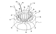
- FIG. 1 is a perspective view for explaining a stator according to a first embodiment of the present invention, and is a perspective view showing a stator iron core and a part of a winding wire.
- the stator 20 according to the first embodiment includes a winding for each phase. Therefore, in the case where the electric motor in which the stator 20 is used is connected to a three-phase AC power source, FIG. 1 shows the winding of one of the three phases.
- the electric motor used for the stator 20 will be described as being connected to a three-phase AC power supply.
- each of the three phases will be referred to as a U phase, a V phase, and a W phase.
- the stator 20 has a U-phase winding 7, a V-phase winding 8, and a W-phase winding from the outer peripheral side to the inner peripheral side of the stator 20. It is arranged in the order of 9. That is, FIG. 1 illustrates the U-phase winding 7.
- the stator 20 is provided with a hollow cylindrical stator core 1.
- the stator core 1 includes a hollow cylindrical back yoke 1a having a through hole 1d formed in the center thereof.
- the rotor is arranged in the through hole 1d.
- the stator core 1 includes a plurality of teeth 1b protruding from the inner peripheral surface of the back yoke 1a.
- Each tooth 1b extends along the axial direction of the through hole 1d. In other words, each tooth 1b extends along the axial direction of the stator core 1.
- the teeth 1b are arranged at regular intervals in the circumferential direction of the stator core 1. As a result, the slot 1c is formed between the adjacent teeth 1b.
- the slots 1c are arranged on the inner peripheral side of the stator core 1 with a predetermined interval in the circumferential direction of the stator core 1.
- the stator core 1 is formed by punching electromagnetic steel plates into an annular shape and stacking annular electromagnetic steel sheets.
- the inside of each slot 1c is insulated by the slot film 2.
- the stator 20 has one slot for each pole and each phase.
- the windings of the same phase have the same number of coils as the number of poles.
- the U-phase winding 7 has the same number of coils as the number of poles
- the V-phase winding 8 also has the same number of coils as the number of poles
- the W-phase winding 9 also has the same number of poles. It has an equal number of coils.
- the number of slots 1c is 18, and the three-phase, six-pole stator 20 is illustrated.
- the U-phase winding 7 has six coils. Further, these six coils are arranged every three slots. The same applies to the six coils of the V-phase winding 8 and the W-phase winding 9.
- FIG. 2 is a perspective view showing an outer peripheral coil of the U-phase winding in the stator according to the first embodiment of the present invention.
- FIG. 3 is a perspective view showing an inner circumference side coil of the U-phase winding in the stator according to the first embodiment of the present invention.
- FIG. 4 is a perspective view showing an outer circumference side coil and an inner circumference side coil of the U-phase winding in the stator according to the first embodiment of the present invention. Details of the U-phase winding 7 will be described below with reference to FIGS. 2 to 4 and FIG. 1 described above.
- the configurations of the V-phase winding 8 and the W-phase winding 9 are the same as those of the U-phase winding 7, and the description thereof will be omitted.
- FIGS. 1 to 4 and the drawings described later in the first embodiment a crossover connecting the coils of the U-phase winding 7, a lead wire of the U-phase winding 7, and a coil of the V-phase winding 8 are shown. Illustrations of the crossover wire connecting between them, the lead wire of the V-phase winding 8, the crossover wire connecting between the coils of the W-phase winding 9, and the lead wire of the W-phase winding 9 are omitted.
- the U-phase winding 7 is a distributed winding and concentric winding wound through the slot 1c. As described above, the U-phase winding 7 includes six coils. Half of these six coils are the outer peripheral side coils 3. The other half of these six coils is the inner circumference side coil 4. The outer peripheral coil 3 is arranged on the outer peripheral side of the inner peripheral coil 4. The outer peripheral side coils 3 and the inner peripheral side coils 4 are arranged alternately in the circumferential direction of the stator core 1.
- the six coils of the U-phase winding 7 are arranged every three slots. That is, the outer peripheral side coils 3 and the inner peripheral side coils 4 are alternately arranged every three slots. Therefore, when observing the outer peripheral side coil 3 and the inner peripheral side coil 4 which are adjacent to each other, a part of the outer peripheral side coil 3 and a part of the inner peripheral side coil 4 are housed in the same slot 1c. .. In other words, when the outer peripheral side coil 3, the inner peripheral side coil 4, and the slot 1c accommodating a part thereof are observed from the inner peripheral side of the stator core 1, the outer peripheral side coil 3 uses the slot 1c as a reference. It is arranged on the side opposite to the inner circumference side coil 4.
- FIG. 5 is a plan view for explaining the stator according to the first embodiment of the present invention, and is a perspective view showing a stator core and a U-phase winding.
- FIG. 6 is a plan view for explaining the stator according to the first embodiment of the present invention, and is a perspective view showing the stator core, the U-phase winding, and the V-phase winding.
- FIG. 7 is a plan view for explaining the stator according to the first embodiment of the present invention, and is a perspective view showing the stator core, the U-phase winding, the V-phase winding, and the W-phase winding. ..
- the U-phase winding 7 provided on the stator core 1 is formed such that the coil end of the inner circumference side coil 4 and the coil end of the outer circumference side coil 3 overlap each other in a plan view.
- the coil ends of the coils forming the phase winding 7 are arranged in an annular shape.
- the coil end is a portion of the coil that is not housed in the slot 1c.
- the V-phase winding 8 provided on the stator core 1 on the inner peripheral side of the U-phase winding 7 has the coil end of the inner peripheral side coil 4 and the outer peripheral side coil 4 in plan view.
- the coil ends of the coils forming the V-phase winding 8 are arranged in an annular shape.
- the W-phase winding 9 provided on the stator core 1 on the inner peripheral side of the V-phase winding 8 has a coil end of the inner peripheral side coil 4 and an outer peripheral side coil in plan view.
- the coil ends of the coils forming the W-phase winding 9 are arranged in an annular shape.
- FIGS. 8 to 10 are perspective views for explaining a step of inserting the U-phase winding in the slot of the stator core of the stator according to the first embodiment of the present invention.
- 8 to 10 in order to distinguish the three outer peripheral coils 3, each of the three outer peripheral coils 3 is referred to as an outer peripheral first coil 3a, an outer peripheral second coil 3b, and an outer peripheral third coil. It is shown as 3c.
- FIGS. 8 to 10 in order to distinguish the three inner circumference side coils 4, each of the three inner circumference side coils 4 is referred to as an inner circumference side first coil 4a, an inner circumference side second coil 4b, and It is shown as an inner peripheral side third coil 4c.
- the coil insertion jig used when inserting the U-phase winding 7 into the slot 1c of the stator core 1 includes a plurality of rod-shaped insertion blades 13. These insertion blades 13 are arranged in an annular shape.
- the electric wire is wound around a winding die (not shown), and the inner peripheral side first coil 4a, the inner peripheral side second coil 4b and the inner peripheral side are wound.
- the third coil 4c is formed.
- the inner peripheral side first coil 4a, the inner peripheral side second coil 4b, and the inner peripheral side third coil 4c are inserted between the insertion blades 13, and the inner peripheral side first coil 4a,
- the inner circumference side second coil 4b and the inner circumference side third coil 4c are arranged.
- the winding die (not shown) is rotated by three slots around the plurality of insertion blades 13 arranged in an annular shape.
- the electric wire is wound around a winding die (not shown) to form the outer peripheral side first coil 3a, the outer peripheral side second coil 3b, and the outer peripheral side third coil 3c.
- the outer peripheral side first coil 3a, the outer peripheral side second coil 3b, and the outer peripheral side third coil 3c are inserted between the insertion blades 13, and the outer peripheral side first coil 3a and the outer peripheral side first coil 3a are inserted.
- Two coils 3b and an outer peripheral side third coil 3c are arranged.
- the outer coil 3 and the inner coil 4 have the same number of turns and the same resistance value due to the characteristics of the electric motor.
- the outer peripheral side coil 3 and the inner peripheral side coil 4 are formed of electric wires having the same diameter, and the outer peripheral side coil 3 and the inner peripheral side coil 4 have the same circumferential length.
- the number of turns is the same as that of 4, and the resistance values are the same.
- the outer circumference side coil 3 and the inner circumference side coil 4 are also formed.
- the coil 4 has the same number of turns and the same resistance value.
- FIG. 11 is an explanatory diagram for explaining a conventional process for forming a wave winding.
- FIG. 11 shows a process until the winding formation of the wave winding is completed.
- the electric wire is wound in an annular shape to form the annular coil 10.
- a plurality of locations on the outer peripheral portion of the annular coil 10 are pushed toward the inner peripheral side to form the star-shaped coil 11 having an uneven shape.
- the winding formation of the wave winding is completed, and the winding is in the state before it is inserted into the slot. Since the winding of the wave winding is formed in this manner, external force applied to the winding when the star coil 11 is formed damages the insulating coating of the winding, lowers the insulation performance, and lowers the reliability. It may happen.
- the star-shaped coil 11 of the wave winding is formed in the process until the winding formation is completed.
- the external force applied when doing is unnecessary.
- the U-phase winding 7 according to the first embodiment it is possible to prevent the insulation film of the winding from being damaged or the like, and the insulation performance from being lowered.
- the V-phase winding 8 and the W-phase winding 9 according to the first embodiment it is possible to prevent the insulation performance of the windings from being damaged and the insulation performance from decreasing. That is, it is possible to prevent the reliability of the stator 20 and the electric motor using the stator 20 from decreasing.
- the winding formation of the outer peripheral coil 3 and the inner peripheral coil 4 of the U-phase winding 7 is completed, and the outer peripheral coil 3 of the U-phase winding 7 is completed.
- the inner circumferential side coil 4 is arranged at a position before being inserted into the slot 1c.
- the outer peripheral side coil 3 and the inner peripheral side are used by using the insertion stripper 14 of the coil insertion jig shown in FIG.
- the coil 4 is inserted into the slot 1c.
- the stator core 1 is arranged above the outer peripheral coil 3 and the inner peripheral coil 4.
- the insertion stripper 14 arranged below the outer peripheral side coil 3 and the inner peripheral side coil 4 is raised, and the outer peripheral side coil 3 and the inner peripheral side coil 4 are pushed up by the insert stripper 14.
- the outer peripheral side coil 3 and the inner peripheral side coil 4 are inserted into the slot 1c.
- the insertion blade 13 may be moved together with the insertion stripper 14.
- FIG. 12 is an explanatory diagram for explaining a conventional concentric winding forming process.
- each winding of each phase has three coils 12.
- FIG. 12 shows three coils 12 of a conventional U-phase winding of concentric winding.
- the electric wire is wound around a winding die (not shown) to form the three coils 12. Then, as shown in FIG. 12, each coil 12 is inserted between the insertion blades 13 arranged in an annular shape. Then, each coil 12 is pushed up by an insertion stripper 14 (not shown) to insert each coil 12 into the slot.
- the U-phase winding 7, the V-phase winding 8, and the W-phase winding 9 of the stator 20 according to the first embodiment use the same coil insertion jig as the conventional one, and the stator core 1 Can be inserted into the slot 1c.
- FIG. 13 is a plan view of the stator according to the first embodiment of the present invention.
- FIG. 14 is a plan view of a stator using a conventional concentric winding.
- the width of the coil of the winding of the same phase in plan view is L.
- the coil diameter of the winding of the same phase is L.
- the width of the coil end of the winding of the same phase in plan view is also L.
- the conventional stator using the concentric winding has a maximum width of 2 L in plan view of the coil end.
- the number of coils of the same phase winding is twice that of the conventional one. Therefore, in the stator 20 according to the first embodiment, the number of turns of the coil of the same phase is half that of the conventional coil, and the width of the coil of the same phase of the coil in plan view is L/2. Therefore, in the stator 20 according to the first embodiment, when the axial length of the stator core 1 in the coils of the same phase winding is set to be the same as the conventional one, the coil ends of the coils of the same phase are The width in plan view is L/2. Further, in the stator 20 according to the first embodiment, the coil ends of the windings of the three phases overlap in the radial direction of the stator core 1.
- the width of the coil end in plan view is 3L/2.
- the coil end can be downsized as compared with the conventional stator using the concentric winding. Therefore, the stator 20 according to the first embodiment can reduce the resistance value of the winding as compared with the conventional stator using the concentric winding. That is, the stator 20 according to the first embodiment can achieve a smaller size and higher performance of the electric motor than a conventional stator using concentric windings.
- the coil end of the outer peripheral coil 3 and the coil end of the inner peripheral coil 4 are fixed.
- the axial length of the stator core 1 at the coil ends of the windings of the same phase is set to L, with the core cores 1 stacked in the axial direction.
- the stator 20 according to the first embodiment has a hollow cylindrical shape, and the stator core 1 in which a plurality of slots 1c are arranged on the inner peripheral side at regular intervals in the circumferential direction, 1c, distributed winding and concentric winding.
- the number of slots for each pole and each phase is 1, and the windings of the same phase have the same number of coils as the number of poles.
- half of the coils of the windings of the same phase are the outer peripheral side coils 3, and are arranged on the outer peripheral side of the inner peripheral side coil 4, which is the other half of the coils of the same phase windings. ..
- the outer peripheral side coils 3 and the inner peripheral side coils 4 are arranged alternately in the circumferential direction of the stator core 1. Further, when observing the outer peripheral side coil 3 and the inner peripheral side coil 4 which are adjacent to each other, a part of the outer peripheral side coil 3 and a part of the inner peripheral side coil 4 are accommodated in the same slot 1c, and are in the same layer.
- the coil ends of the coils forming the winding are arranged in an annular shape.
- the stator 20 according to the first embodiment includes distributed windings. Further, by disposing the coils of the windings of the same phase as in the stator 20 according to the first embodiment, the coil end can be downsized and the coil circumference can be shortened, so that the resistance value of the windings can be reduced. It can be reduced. Therefore, by using the stator 20 according to the first embodiment, it is possible to reduce the size and performance of the electric motor.
- the windings of the stator 20 according to the first embodiment are concentric. When forming the concentric winding, the external force applied when forming the star coil of the wave winding is unnecessary. Therefore, by using the stator 20 according to the first embodiment, it is possible to suppress deterioration of reliability of the electric motor.
- the coil end can be downsized as compared with the conventional stator using the concentric winding, so that the amount of electric wires used can be reduced. Therefore, the stator 20 according to the first embodiment can be manufactured at a lower cost than the conventional stator using the concentric winding.
- the stator 20 since the stator 20 according to the first embodiment uses the concentric winding, the advantage of the wave winding that can shorten the coil circumference and the advantage of the lap winding that can downsize the coil end are provided. While having both, it can also be manufactured at a lower cost than a stator using a wave winding or a lap winding. More specifically, in order to form the wave winding, in addition to the step of winding the electric wire to form the annular coil 10 as described above, a step of forming the star coil 11 is also required. For this reason, the winding device that forms the winding of the wave winding becomes large, and the occupation rate of the production site increases. Further, the jig for forming the star-shaped coil 11 has a complicated structure. Therefore, when the stator having different numbers of slots is to be manufactured, it is not easy to change the number of jigs forming the concavo-convex portion of the star coil 11. Therefore, the stator using the wave winding becomes expensive.
- a winding unit in which an electric wire is wound in a spiral shape, into a predetermined number of windings and dividing the winding unit into units.
- the correction of the coil position when mounting the coil on the coil insertion jig is performed manually or with an expensive winding device provided with a correction mechanism having a complicated structure. For this reason, the stator using the windings of lap winding becomes expensive.
- the concentric winding equipment and jig that exist in the related art can be used as they are. Further, the structure of the jig itself used when winding and forming the concentric winding coil is simple. Further, it is possible to cope with a difference in the shape of the stator core 1 and a change in the number of the slots 1c with a simple structure such as the above-mentioned coil insertion jig and the like, and only by replacing inexpensive jigs.
- the winding machine is versatile enough to support multiple models.
- stator 20 according to the first embodiment uses the concentric winding, the advantage of the wave winding capable of shortening the coil circumferential length and the advantage of the lap winding capable of reducing the coil end can be achieved. It is also possible to manufacture at low cost compared with a stator that uses a wave winding and a lap winding while having the above.
- Embodiment 2 an example of a wire connection structure of each coil of the stator 20 shown in the first embodiment will be described.
- items that are not particularly described are the same as those in the first embodiment, and the same functions and configurations as those in the first embodiment will be described using the same reference numerals.
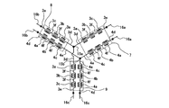
- FIG. 15 is a figure which shows an example of the wire connection structure of the stator which concerns on Embodiment 2 of this invention.
- each of the U-phase winding 7, the V-phase winding 8 and the W-phase winding 9 has three outer peripheral coils 3 and 3.
- Two inner circumference side coils 4 are provided.
- each of the outer peripheral coils 3 of the same phase is connected to the adjacent outer coil 3 by a connecting wire 3f.
- the outer peripheral coils 3 of the same phase are connected in series by the crossover wire 3f.
- the lead wire of the outer circumference side first coil 3a and the lead wire of the outer circumference side second coil 3b are connected by a crossover wire 3f.
- the lead wire of the outer circumference side second coil 3b and the lead wire of the outer circumference side third coil 3c are connected by a crossover wire 3f.
- each of the inner circumference side coils 4 of the same phase is connected to the adjacent inner circumference side coil 4 by a crossover wire 4f.
- the inner peripheral side coils 4 of the same phase are connected in series by the crossover 4f.
- the lead wire of the inner circumference side first coil 4a and the lead wire of the inner circumference side second coil 4b are connected by a crossover wire 4f.
- the lead wire of the inner circumference side second coil 4b and the lead wire of the inner circumference side third coil 4c are connected by a crossover wire 4f.
- the lead wires 3e of the third coil 3c on the outer peripheral side of each phase are short-circuited with each other to form a neutral point 15a.
- the lead wires 4d of the first coil 4a on the inner circumference side of each phase are short-circuited with each other to form a neutral point 15b.
- the lead wire 3e of the outer peripheral side third coil 3c is a lead wire at the end of winding of the outer peripheral side third coil 3c.
- the lead wire 4d of the inner circumference side first coil 4a is a lead wire at the beginning of winding of the inner circumference side first coil 4a.
- the lead wire 3d of the first coil 3a on the outer circumference side and the lead wire 4e of the third coil 4c on the inner circumference side of the same phase are short-circuited, and the short-circuited portion is connected to the power supply via the lead wire 16.
- the lead wire 3d of the outer circumference side first coil 3a and the lead wire 4e of the inner circumference side third coil 4c are short-circuited, and the short-circuited portion is the U-phase lead wire 16a. Connected to the power supply via.
- the lead wire 3d of the outer circumference side first coil 3a and the lead wire 4e of the inner circumference side third coil 4c are short-circuited, and the short-circuited portion is connected to the power source via the V-phase lead wire 16b. It is connected.
- the lead wire 3d of the outer circumference side first coil 3a and the lead wire 4e of the inner circumference side third coil 4c are short-circuited, and the short-circuited portion is connected to the power source via the W-phase lead wire 16c. It is connected.
- the lead wire 3d of the outer peripheral side first coil 3a is the lead wire at the beginning of winding of the outer peripheral side first coil 3a.
- the lead wire 4e of the inner circumference side third coil 4c is a lead wire at the winding end of the inner circumference side third coil 4c.
- each coil of the stator 20 according to the second embodiment has a three-phase Y connection structure with two parallel circuits.
- the three-phase Y connection by two parallel circuits may be described as 2//Y connection.
- each coil has a Y connection structure in which coils of the same phase are connected in series, or coils of the same phase are connected in parallel.
- a three-phase Y connection structure is formed by the above three parallel circuits.
- the three-phase Y connection by three parallel circuits may be described as 3//Y connection. That is, in such a stator using the conventional concentric winding, the connection structure of each coil has only two options.
- the windings of each phase are each provided with six coils having an even number. Therefore, in the stator 20 according to the second embodiment, in addition to the conventional stator wire connection structure using concentric windings, the 2//Y wire connection structure can be adopted as described above. .. Therefore, in the stator 20 configured as in the second embodiment, in addition to the effect shown in the first embodiment, the options of the connection structure of each coil are increased, and the degree of freedom in design is increased. You can also get it.
- Embodiment 3 when a plurality of outer peripheral side coils 3 of the same phase are wound and formed, the plurality of outer peripheral side coils 3 are formed without cutting between the outer peripheral side coils 3 and the outer peripheral side coils 3 are wound by an electric wire during formation. A method of forming the crossovers 3f will be described. Similarly, in the third embodiment, when a plurality of inner circumferential side coils 4 of the same phase are wound and formed, the plurality of inner circumferential side coils 4 are formed without cutting between the inner circumferential side coils 4, A method of forming the crossover wire 4f with an electric wire at the time of forming the winding will be described.
- the third embodiment a suitable arrangement of the lead wires connected to the power source in the outer peripheral coil 3 and the inner peripheral coil 4 will be described.
- items not particularly described are the same as those in the first or second embodiment, and the same reference numerals are used for the same functions and configurations as those in the first or second embodiment. Will be described.
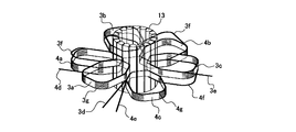
- FIG. 16 is a perspective view for explaining an example of a stator according to the third embodiment of the present invention, and is a perspective view showing a stator core and a part of a winding wire.
- the winding shown in FIG. 16 is the U-phase winding 7.
- the outer peripheral side first coil 3a and the outer peripheral side second coil 3b are connected by a connecting wire 3f.
- the outer peripheral side second coil 3b and the outer peripheral side third coil 3c are connected by a connecting wire 3f.
- These crossover wires 3f do not cut the electric wire between the coils when winding the outer peripheral side first coil 3a, the outer peripheral side second coil 3b, and the outer peripheral side third coil 3c and form each coil continuously. It is formed by forming.
- the inner circumference side first coil 4a and the inner circumference side second coil 4b are connected by a crossover wire 4f.
- the inner circumference side second coil 4b and the inner circumference side third coil 4c are connected by a connecting wire 4f.
- These crossover wires 4f do not cut the electric wire between the coils when the inner circumference side first coil 4a, the inner circumference side second coil 4b, and the inner circumference side third coil 4c are wound and formed.
- the outer peripheral side coil 3 and the inner peripheral side coil 4 are wound and formed as follows.
- FIG. 17 to 19 are perspective views for explaining the process of forming the U-phase winding of the stator according to the third embodiment of the present invention.
- the step of winding the V-phase winding 8 and the W-phase winding 9 is the same as the step of winding the U-phase winding 7.
- the electric wire is wound around a winding die (not shown) while leaving the electric wire portion to be the lead wire 4d to form the inner peripheral side first coil 4a. Then, the inner circumferential first coil 4 a is inserted between the insertion blades 13. Next, a winding die (not shown) is rotated around the plurality of insertion blades 13 arranged in an annular shape. Then, the electric wire is wound around a winding die (not shown) without cutting the electric wire after forming the inner peripheral side first coil 4a to form the inner peripheral side second coil 4b. Then, the inner peripheral second coil 4b is inserted between the insertion blades 13.
- a winding die (not shown) is rotated around the plurality of insertion blades 13 arranged in an annular shape. Then, the electric wire is wound around a winding die (not shown) without cutting the electric wire after forming the inner peripheral side second coil 4b to form the inner peripheral side third coil 4c. Then, the inner third coil 4c is inserted between the insertion blades 13. Finally, after inserting the inner peripheral side third coil 4c between the insertion blades 13, the electric wire is cut while leaving the electric wire portion to be the lead wire 4e.
- the outer peripheral side first coil 3 a, the outer peripheral side second coil 3 b, and the outer peripheral side third coil 3 c are wound and formed, and these coils are provided between the insertion blades 13. insert.
- the electric wire is wound around a winding mold (not shown), leaving the electric wire portion that becomes the lead wire 3d, to form the outer peripheral side first coil 3a.
- the outer peripheral side first coil 3 a is inserted between the insertion blades 13.
- a winding die (not shown) is rotated around the plurality of insertion blades 13 arranged in an annular shape.
- the electric wire is wound around a winding die (not shown) without cutting the electric wire to form the outer peripheral side second coil 3b. Then, the outer peripheral second coil 3b is inserted between the insertion blades 13. Next, a winding die (not shown) is rotated around the plurality of insertion blades 13 arranged in an annular shape. Then, after the outer peripheral side second coil 3b is formed, the electric wire is wound around an unillustrated winding die without cutting the electric wire to form the outer peripheral side third coil 3c. Then, the outer peripheral third coil 3c is inserted between the insertion blades 13.
- FIG. 18 shows an image of the outer peripheral side first coil 3a, the outer peripheral side second coil 3b, and the outer peripheral side third coil 3c after the winding formation is completed.
- each of the outer peripheral side second coil 3b and the outer peripheral side third coil 3c is inserted between the insertion blades 13 after the winding formation of one coil is completed.
- the outer circumference side coil 3 and the inner circumference side coil 4 are arranged as shown in FIG. 19, the outer circumference side coil 3 and the inner circumference side coil 4 are inserted into the slot 1c as shown in the first embodiment, and thereby fixed.
- the child 20 is in the state shown in FIG. In FIG. 16, the lead wire 3d of the outer coil 3 and the lead wire 4e of the inner coil 4 are arranged in the same slot 1c.
- the phase of the outer coil 3 with respect to the inner coil 4 may be different from that of FIG. 16 with the axis of the stator core 1 as the center of rotation.
- FIG. 20 is a perspective view for explaining another example of the stator according to the third embodiment of the present invention, and is a perspective view showing the stator core and the U-phase winding.
- the outer peripheral side second coil 3b is arranged between the inner peripheral side first coil 4a and the inner peripheral side second coil 4b.
- the outer peripheral side first coil 3a is arranged between the inner peripheral side first coil 4a and the inner peripheral side second coil 4b.
- the outer peripheral side coil 3 and the inner peripheral side coil 4 are wound and formed as follows.
- 21 and 22 are perspective views for explaining the process of winding the U-phase winding of the stator shown in FIG.
- the step of winding the V-phase winding 8 and the W-phase winding 9 is the same as the step of winding the U-phase winding 7.
- the winding formation of the outer circumference side coil 3 and the inner circumference side coil 4 in the U-phase winding 7 of the stator 20 shown in FIG. It is performed in the same manner as the step indicated by 19. Specifically, in the process shown in FIGS. 17 to 19, the outer peripheral side second coil 3b is arranged between the inner peripheral side first coil 4a and the inner peripheral side second coil 4b. On the other hand, as shown in FIGS. 21 and 22, in the winding forming step of the outer peripheral side coil 3 in the U-phase winding 7 of the stator 20 shown in FIG. 20, the inner peripheral side first coil 4a and the inner peripheral side first coil 4a are formed. The outer peripheral side first coil 3a is disposed between the two coils 4b.
- the outer peripheral side coil 3 and the inner peripheral side coil 4 are arranged as shown in FIG. 22, the outer peripheral side coil 3 and the inner peripheral side coil 4 are inserted into the slots 1c as shown in the first embodiment to fix the coil.
- the child 20 will be in the state shown in FIG. In FIG. 20, the lead wire 3e of the outer coil 3 and the lead wire 4d of the inner coil 4 are arranged in the same slot 1c.
- the lead wire of the outer peripheral coil 3 and the lead wire of the inner peripheral coil 4 are arranged in the same slot 1c, so that The effect can be obtained.
- the lead wire 3d of the outer circumference side first coil 3a arranged in the same slot 1c as the lead wire 4e of the inner circumference side third coil 4c is the outer circumference side first coil.
- the end portion 3g on the inner peripheral side third coil 4c side is arranged.
- the lead wire 4e of the inner circumference side third coil 4c which is arranged in the same slot 1c as the lead wire 3d of the outer circumference side first coil 3a, is the same as the lead wire 4e of the stator core 1 in the inner circumference side third coil 4c. It is arranged at an end 4g on the outer peripheral side first coil 3a side among the ends in the radial direction.
- the lead wire 3d of the outer peripheral side first coil 3a and the lead wire 4e of the inner peripheral side third coil 4c of the same phase are The wiring work can be performed by regarding it as one lead wire. For this reason, it is possible to reduce the number of insulating parts used in the work of connecting the lead wire 3d and the lead wire 4e and the connecting portion between the lead wire 3d and the lead wire 4e. Therefore, when the coils of the stator 20 shown in FIG. 16 are connected as shown in FIG. 15, the workability of assembling the stator 20 is improved, and the stator 20 can be manufactured at low cost.
- the lead wire 3e of the outer circumference side third coil 3c arranged in the same slot 1c as the lead wire 4d of the inner circumference side first coil 4a is the outer circumference side third coil.
- the end portion 3h on the side opposite to the inner peripheral side first coil 4a side is arranged.
- the lead wire 4d of the inner circumference side first coil 4a which is arranged in the same slot 1c as the lead wire 3e of the outer circumference side third coil 3c, is the same as the lead wire 4d of the stator core 1 in the inner circumference side first coil 4a.
- the end portion 4h on the side opposite to the outer peripheral side third coil 3c side is arranged.
- FIG. 23 is a diagram showing an example of the wire connection structure of the stator shown in FIG.
- a plurality of coils forming the same phase may be connected to the power supply by a plurality of lead wires.
- the coils of the stator 20 shown in FIG. 20 may be connected as shown in FIG.
- the lead wire 3e of the outer circumference side third coil 3c and the lead wire 4d of the inner circumference side first coil 4a of the same phase may be connected to the power supply by different lead wires 16.
- the distinction between the lead wire 3e and the lead wire 4d becomes clear, so that the lead wire 3e and the lead wire 4d have incorrect leads.
- the connection of the wire 16 can be suppressed, and it becomes easy to connect the correct lead wire 16 to the lead wire 3e and the lead wire 4d.
- the workability of assembling the stator 20 is improved and the stator 20 can be manufactured at low cost.
- the reliability of the stator 20 can be improved.
- the outer circumference side coil 3 and the inner circumference side coil 4 are formed of electric wires having different diameters, different magnitudes of current are supplied to the outer circumference side coil 3 and the inner circumference side coil 4. Therefore, it becomes easy to connect the correct lead wire 16 to the lead wire 3e and the lead wire 4d when the outer circumference side coil 3 and the inner circumference side coil 4 are composed of electric wires having different diameters. Especially useful for.
- FIG. 24 is a sectional view showing an example of an electric motor according to Embodiment 4 of the present invention.
- FIG. 24 is a cross-sectional view of the electric motor 30 taken along a virtual plane parallel to the center of rotation of the rotor 31.
- the electric motor 30 includes the stator 20 shown in any of the first to third embodiments, and the rotor 31 rotatably arranged on the inner peripheral side of the stator 20.
- a through hole 31 a, to which the output shaft is fixed, is formed in the center of the rotor 31 along the center of rotation of the rotor 31.
- the electric motor 30 is, for example, a synchronous electric motor in which the rotor 31 includes a permanent magnet.
- the electric motor 30 according to the fourth embodiment includes the stator 20 shown in any of the first to third embodiments. Therefore, the electric motor 30 can be reduced in size and improved in performance, and can be prevented from lowering in reliability.
- Embodiment 5 an example of a compressor using the electric motor 30 shown in the fourth embodiment will be introduced.
- items not particularly described are the same as those in any of the first to fourth embodiments, and the same functions and configurations as those in any of the first to fourth embodiments are the same. Will be described using the reference sign.
- FIG. 25 is a vertical sectional view showing an example of a compressor according to Embodiment 5 of the present invention.
- the compressor 40 includes the electric motor 30 described in the fourth embodiment and a compression mechanism 41.
- the electric motor 30 and the compression mechanism 41 are connected by a drive shaft 42 fixed to the rotor 31.
- the drive shaft 42 is an output shaft fixed to the through hole 31a of the rotor 31 shown in FIG.
- the compressor 40 also includes a closed container 43.
- the electric motor 30, the compression mechanism 41, and the drive shaft 42 are housed in a closed container 43.
- the sucked refrigerant is compressed by the compression mechanism 41 and then discharged from the compression mechanism 41 into the closed container 43.
- the discharged refrigerant passes between the stator 20 and the rotor 31, etc., and then flows out of the compressor 40 from the discharge pipe 45.
- the compression mechanism 41 according to the fifth embodiment is a twin rotary type compression mechanism, but the type of the compression mechanism 41 is arbitrary.
- Various known compression mechanisms such as a single rotary type compression mechanism, a scroll type compression mechanism, and a screw type compression mechanism can be used as the compression mechanism 41.
- the compressor 40 according to the fifth embodiment includes the electric motor 30 shown in the fourth embodiment. Therefore, the compressor 40 can be reduced in size and improved in performance, and can be prevented from lowering reliability.
- the gap formed between the coil ends of each coil becomes small.
- the wall on the inner diameter side is cylindrical. Therefore, the flow of the refrigerant passing between the stator 20 and the rotor 31 becomes smooth.
- the performance of the compressor 40 according to the fifth embodiment is also improved by improving the flow of the refrigerant passing between the stator 20 and the rotor 31.
- stator core 1a back yoke, 1b teeth, 1c slot, 1d through hole, 2 slot film, 3 outer peripheral coil, 3a outer peripheral first coil, 3b outer peripheral second coil, 3c outer peripheral third coil, 3d Lead wire, 3e lead wire, 3f crossover wire, 3g end portion, 3h end portion, 4 inner circumference side coil, 4a inner circumference side first coil, 4b inner circumference side second coil, 4c inner circumference side third coil 4d lead wire, 4e lead wire, 4f crossover wire, 4g end portion, 4h end portion, 7 U phase winding, 8 V phase winding, 9 W phase winding, 10 annular coil, 11 star coil , 12 coil, 13 insertion blade, 14 insertion stripper, 15a neutral point, 15b neutral point, 16 lead wire, 16a U-phase lead wire, 16b V-phase lead wire, 16c W-phase lead wire, 20 stator, 30 electric motor , 31 rotor, 31a through hole, 40 compressor, 41 compression mechanism, 42 drive shaft, 43 closed container, 44 su
Landscapes
- Engineering & Computer Science (AREA)
- Power Engineering (AREA)
- Windings For Motors And Generators (AREA)
Abstract
Le stator selon la présente invention comprend : un noyau de stator qui présente une forme cylindrique creuse, une pluralité de fentes étant disposées sur le côté circonférentiel intérieur à intervalles prescrits dans la direction circonférentielle ; et des enroulements enroulés à travers les fentes en un enroulement distribué et un enroulement concentrique. Il y a une fente par pôle par phase. Les enroulements de la même phase comprennent le même nombre de bobines que le nombre de pôles. La moitié des bobines sont des bobines côté circonférentiel extérieur et sont disposées sur le côté circonférentiel extérieur de bobines côté circonférentiel intérieur, qui sont la moitié restante des bobines. Les bobines côté circonférentiel extérieur et les bobines côté circonférentiel intérieur sont disposées en alternance dans la direction circonférentielle. Lorsqu'une bobine côté circonférentiel extérieur et une bobine côté circonférentiel intérieur qui sont adjacentes sont observées, une partie de la bobine côté circonférentiel extérieur et une partie de la bobine côté circonférentiel intérieur sont logées dans la même fente. Les extrémités de bobine des bobines constituant les enroulements de la même couche sont disposées selon une forme annulaire.
Priority Applications (4)
| Application Number | Priority Date | Filing Date | Title |
|---|---|---|---|
| CN201980091705.XA CN113454881B (zh) | 2019-02-22 | 2019-02-22 | 定子、电动机以及压缩机 |
| PCT/JP2019/006783 WO2020170422A1 (fr) | 2019-02-22 | 2019-02-22 | Stator, moteur et compresseur |
| CZ2021-374A CZ309363B6 (cs) | 2019-02-22 | 2019-02-22 | Stator, elektrický motor a kompresor |
| JP2021501254A JP7113957B2 (ja) | 2019-02-22 | 2019-02-22 | 固定子、電動機及び圧縮機 |
Applications Claiming Priority (1)
| Application Number | Priority Date | Filing Date | Title |
|---|---|---|---|
| PCT/JP2019/006783 WO2020170422A1 (fr) | 2019-02-22 | 2019-02-22 | Stator, moteur et compresseur |
Publications (1)
| Publication Number | Publication Date |
|---|---|
| WO2020170422A1 true WO2020170422A1 (fr) | 2020-08-27 |
Family
ID=72143528
Family Applications (1)
| Application Number | Title | Priority Date | Filing Date |
|---|---|---|---|
| PCT/JP2019/006783 Ceased WO2020170422A1 (fr) | 2019-02-22 | 2019-02-22 | Stator, moteur et compresseur |
Country Status (4)
| Country | Link |
|---|---|
| JP (1) | JP7113957B2 (fr) |
| CN (1) | CN113454881B (fr) |
| CZ (1) | CZ309363B6 (fr) |
| WO (1) | WO2020170422A1 (fr) |
Cited By (2)
| Publication number | Priority date | Publication date | Assignee | Title |
|---|---|---|---|---|
| WO2023032134A1 (fr) * | 2021-09-02 | 2023-03-09 | 三菱電機株式会社 | Moteur électrique, compresseur et dispositif à cycle de réfrigération |
| CN115997329A (zh) * | 2020-09-11 | 2023-04-21 | 三菱电机株式会社 | 定子、电动机、压缩机以及空调装置 |
Families Citing this family (1)
| Publication number | Priority date | Publication date | Assignee | Title |
|---|---|---|---|---|
| CN120825000B (zh) * | 2025-09-16 | 2025-11-25 | 万向钱潮股份公司 | 一种环状波形线圈绕组的制造方法 |
Citations (2)
| Publication number | Priority date | Publication date | Assignee | Title |
|---|---|---|---|---|
| JPH04156245A (ja) * | 1990-10-17 | 1992-05-28 | Toshiba Corp | 三相電機子巻線 |
| JPH05161291A (ja) * | 1991-11-29 | 1993-06-25 | Toshiba Corp | 三相電機子巻線 |
Family Cites Families (9)
| Publication number | Priority date | Publication date | Assignee | Title |
|---|---|---|---|---|
| JP3621653B2 (ja) * | 2001-03-28 | 2005-02-16 | 三菱電機株式会社 | 回転電機の固定子および固定子鉄心並びにその製造方法 |
| JP3561249B2 (ja) * | 2001-09-17 | 2004-09-02 | 三菱電機株式会社 | 交流発電機の固定子およびその製造方法 |
| JP4631631B2 (ja) * | 2005-09-20 | 2011-02-16 | 株式会社デンソー | 回転電機のステータコイル |
| JP2008061443A (ja) * | 2006-09-01 | 2008-03-13 | Mitsuba Corp | インシュレータ及び電動機 |
| JP2011234531A (ja) * | 2010-04-28 | 2011-11-17 | Toyota Motor Corp | 平角導体を用いた分布巻き固定子構造 |
| JP5560176B2 (ja) * | 2010-12-08 | 2014-07-23 | トヨタ自動車株式会社 | モータ及びモータ製造方法 |
| JP5638723B2 (ja) * | 2012-03-19 | 2014-12-10 | 三菱電機株式会社 | 車両用回転電機の固定子およびその製造方法 |
| JP2014082821A (ja) * | 2012-10-15 | 2014-05-08 | Hitachi Automotive Systems Ltd | 回転電機 |
| JP2015136195A (ja) * | 2013-12-20 | 2015-07-27 | 株式会社豊田自動織機 | 回転電機の固定子 |
-
2019
- 2019-02-22 CN CN201980091705.XA patent/CN113454881B/zh active Active
- 2019-02-22 WO PCT/JP2019/006783 patent/WO2020170422A1/fr not_active Ceased
- 2019-02-22 CZ CZ2021-374A patent/CZ309363B6/cs unknown
- 2019-02-22 JP JP2021501254A patent/JP7113957B2/ja active Active
Patent Citations (2)
| Publication number | Priority date | Publication date | Assignee | Title |
|---|---|---|---|---|
| JPH04156245A (ja) * | 1990-10-17 | 1992-05-28 | Toshiba Corp | 三相電機子巻線 |
| JPH05161291A (ja) * | 1991-11-29 | 1993-06-25 | Toshiba Corp | 三相電機子巻線 |
Cited By (2)
| Publication number | Priority date | Publication date | Assignee | Title |
|---|---|---|---|---|
| CN115997329A (zh) * | 2020-09-11 | 2023-04-21 | 三菱电机株式会社 | 定子、电动机、压缩机以及空调装置 |
| WO2023032134A1 (fr) * | 2021-09-02 | 2023-03-09 | 三菱電機株式会社 | Moteur électrique, compresseur et dispositif à cycle de réfrigération |
Also Published As
| Publication number | Publication date |
|---|---|
| JPWO2020170422A1 (ja) | 2021-09-30 |
| JP7113957B2 (ja) | 2022-08-05 |
| CN113454881B (zh) | 2024-09-06 |
| CZ2021374A3 (cs) | 2021-09-15 |
| CZ309363B6 (cs) | 2022-10-05 |
| CN113454881A (zh) | 2021-09-28 |
Similar Documents
| Publication | Publication Date | Title |
|---|---|---|
| JP4499764B2 (ja) | 電動機 | |
| JP6223835B2 (ja) | アキシャルギャップ型モータ | |
| US20080201935A1 (en) | Manufacturing Method for Rotary Electric Machine and Stator | |
| US10170950B2 (en) | Rotary electric machine and method for manufacturing an armature that is used in the rotary electric machine | |
| KR20120041127A (ko) | 고정자, 브러시리스 모터 및 이의 제조방법 | |
| JPWO2015079732A1 (ja) | 電気機械の電機子 | |
| CN109245346B (zh) | 一种分瓣组合定子 | |
| JP5626758B2 (ja) | ステータ | |
| CN113454880B (zh) | 旋转电机的定子、旋转电机、旋转电机的定子的制造方法及旋转电机的制造方法 | |
| US20190312476A1 (en) | Motor | |
| CN109478813B (zh) | 轴向间隙型旋转电机 | |
| US12009714B2 (en) | Rotating electric machine stator and rotating electric machine | |
| JP2021158873A (ja) | 回転電機 | |
| JP7113957B2 (ja) | 固定子、電動機及び圧縮機 | |
| JP2010506549A (ja) | 回転電気機械のためのステータ | |
| JPWO2017110419A1 (ja) | 回転電機 | |
| JP7086212B2 (ja) | 固定子、電動機、圧縮機、空気調和装置および固定子の製造方法 | |
| WO2014184951A1 (fr) | Stator pour machine électrique tournante | |
| JPH07143697A (ja) | 三相電機子巻線 | |
| JP5095276B2 (ja) | ステータおよびその巻線方法 | |
| JP6468124B2 (ja) | 回転電機の製造方法とその回転電機に用いられるステータの製造装置 | |
| JP6968215B2 (ja) | 回転電機 | |
| JP3494729B2 (ja) | 三相電機子巻線 | |
| TWI548180B (zh) | Variable frequency motor device | |
| CN113890222A (zh) | 电机定子、电机、电机定子绕线装置和电机定子制作方法 |
Legal Events
| Date | Code | Title | Description |
|---|---|---|---|
| 121 | Ep: the epo has been informed by wipo that ep was designated in this application |
Ref document number: 19915805 Country of ref document: EP Kind code of ref document: A1 |
|
| ENP | Entry into the national phase |
Ref document number: 2021501254 Country of ref document: JP Kind code of ref document: A |
|
| NENP | Non-entry into the national phase |
Ref country code: DE |
|
| 122 | Ep: pct application non-entry in european phase |
Ref document number: 19915805 Country of ref document: EP Kind code of ref document: A1 |