WO2020170563A1 - Procédé de commande destiné à une machine de coulée continue, dispositif de commande destiné à une machine de coulée continue, et procédé de fabrication de brame - Google Patents
Procédé de commande destiné à une machine de coulée continue, dispositif de commande destiné à une machine de coulée continue, et procédé de fabrication de brame Download PDFInfo
- Publication number
- WO2020170563A1 WO2020170563A1 PCT/JP2019/048374 JP2019048374W WO2020170563A1 WO 2020170563 A1 WO2020170563 A1 WO 2020170563A1 JP 2019048374 W JP2019048374 W JP 2019048374W WO 2020170563 A1 WO2020170563 A1 WO 2020170563A1
- Authority
- WO
- WIPO (PCT)
- Prior art keywords
- molten steel
- casting machine
- continuous casting
- mold
- flow index
- Prior art date
- Legal status (The legal status is an assumption and is not a legal conclusion. Google has not performed a legal analysis and makes no representation as to the accuracy of the status listed.)
- Ceased
Links
Images



Classifications
-
- B—PERFORMING OPERATIONS; TRANSPORTING
- B22—CASTING; POWDER METALLURGY
- B22D—CASTING OF METALS; CASTING OF OTHER SUBSTANCES BY THE SAME PROCESSES OR DEVICES
- B22D37/00—Controlling or regulating the pouring of molten metal from a casting melt-holding vessel
-
- B—PERFORMING OPERATIONS; TRANSPORTING
- B22—CASTING; POWDER METALLURGY
- B22D—CASTING OF METALS; CASTING OF OTHER SUBSTANCES BY THE SAME PROCESSES OR DEVICES
- B22D11/00—Continuous casting of metals, i.e. casting in indefinite lengths
- B22D11/16—Controlling or regulating processes or operations
- B22D11/18—Controlling or regulating processes or operations for pouring
- B22D11/181—Controlling or regulating processes or operations for pouring responsive to molten metal level or slag level
- B22D11/182—Controlling or regulating processes or operations for pouring responsive to molten metal level or slag level by measuring temperature
-
- B—PERFORMING OPERATIONS; TRANSPORTING
- B22—CASTING; POWDER METALLURGY
- B22D—CASTING OF METALS; CASTING OF OTHER SUBSTANCES BY THE SAME PROCESSES OR DEVICES
- B22D11/00—Continuous casting of metals, i.e. casting in indefinite lengths
- B22D11/10—Supplying or treating molten metal
- B22D11/11—Treating the molten metal
- B22D11/111—Treating the molten metal by using protecting powders
-
- B—PERFORMING OPERATIONS; TRANSPORTING
- B22—CASTING; POWDER METALLURGY
- B22D—CASTING OF METALS; CASTING OF OTHER SUBSTANCES BY THE SAME PROCESSES OR DEVICES
- B22D11/00—Continuous casting of metals, i.e. casting in indefinite lengths
- B22D11/10—Supplying or treating molten metal
- B22D11/11—Treating the molten metal
- B22D11/114—Treating the molten metal by using agitating or vibrating means
- B22D11/115—Treating the molten metal by using agitating or vibrating means by using magnetic fields
-
- B—PERFORMING OPERATIONS; TRANSPORTING
- B22—CASTING; POWDER METALLURGY
- B22D—CASTING OF METALS; CASTING OF OTHER SUBSTANCES BY THE SAME PROCESSES OR DEVICES
- B22D11/00—Continuous casting of metals, i.e. casting in indefinite lengths
- B22D11/16—Controlling or regulating processes or operations
-
- B—PERFORMING OPERATIONS; TRANSPORTING
- B22—CASTING; POWDER METALLURGY
- B22D—CASTING OF METALS; CASTING OF OTHER SUBSTANCES BY THE SAME PROCESSES OR DEVICES
- B22D11/00—Continuous casting of metals, i.e. casting in indefinite lengths
- B22D11/16—Controlling or regulating processes or operations
- B22D11/18—Controlling or regulating processes or operations for pouring
-
- B—PERFORMING OPERATIONS; TRANSPORTING
- B22—CASTING; POWDER METALLURGY
- B22D—CASTING OF METALS; CASTING OF OTHER SUBSTANCES BY THE SAME PROCESSES OR DEVICES
- B22D11/00—Continuous casting of metals, i.e. casting in indefinite lengths
- B22D11/16—Controlling or regulating processes or operations
- B22D11/18—Controlling or regulating processes or operations for pouring
- B22D11/181—Controlling or regulating processes or operations for pouring responsive to molten metal level or slag level
- B22D11/186—Controlling or regulating processes or operations for pouring responsive to molten metal level or slag level by using electric, magnetic, sonic or ultrasonic means
Definitions
- the present invention relates to a continuous casting machine control method, a continuous casting machine control device, and a slab manufacturing method.
- Patent Document 1 describes a method of applying a magnetic field to molten steel in a mold. By applying a magnetic field to the molten steel in the mold to control the molten steel flow, the quality of the slab can be stabilized. However, even if a magnetic field is applied to the molten steel, it is difficult to completely control the molten steel flow due to an unexpected operational fluctuation. Therefore, there has been proposed a technique of controlling the operation by using the temperature measurement result of the molten steel by the temperature measurement element embedded in the mold copper plate. For example, Patent Document 2 describes a method of highly accurately estimating the molten steel flow by correcting the molten steel flow in the mold based on the copper plate temperature data in the mold.
- the molten steel poured into the mold through the immersion nozzle starts to solidify into a shell shape from the wall surface of the mold (hereinafter, the steel solidified into a shell is referred to as a solidified shell), and with the progress of casting. Increase the thickness of the solidified shell. Bubbles and inclusions are suspended in the molten steel poured into the mold, but if these bubbles and inclusions are captured by the solidification shell and solidification proceeds as it is, the above defects occur.
- Patent Document 3 discloses a technique for suppressing the occurrence of defects due to insufficient molten steel flow velocity at the solidification interface when the casting speed is relatively slow such as about 1.6 m/min. .. Specifically, this technique is based on the position of the discharge port of the immersion nozzle with respect to the position where the moving magnetic field is applied during continuous casting by applying a moving magnetic field so that a braking force acts on the molten steel discharge flow discharged from the immersion nozzle. And the discharge angle is within an appropriate range.
- Patent Document 2 describes a method for estimating the molten steel flow in the mold with high accuracy, but estimates the molten steel flow index that is a factor that causes impurities to be mixed into the slab in the mold, and sets the molten steel flow index appropriately. Controlling within range is not disclosed or suggested. In order to manufacture a high quality slab, it is necessary to estimate a molten steel flow index that causes impurities to be mixed into the slab in the mold and control the molten steel flow index within an appropriate range. Therefore, it is difficult to manufacture a high quality slab only by the method described in Patent Document 2.
- Patent Document 3 describes a method of controlling the molten steel flow velocity at the solidification interface within an appropriate range, but this appropriate range is defined only by the geometrical relationship of the equipment.
- factors that cause fluctuations in the molten steel flow rate such as the inclusion of inclusions in the nozzle holes of the dipping nozzle, which causes uneven flow.
- the present invention has been made in view of the above problems, and an object thereof is to control a continuous casting machine capable of manufacturing a high quality cast piece, a control device for a continuous casting machine, and a method for manufacturing a cast piece. To provide.
- Control method of the continuous casting machine using the operating conditions of the continuous casting machine and the temperature data of the molten steel in the mold, the molten steel flow state estimation step of estimating the flow state of the molten steel online in the mold, Based on the flow state of the molten steel estimated in the molten steel flow state estimation step, a molten steel flow index calculation step for online calculating a molten steel flow index that is a factor that causes impurities to mix into the slab in the mold, and the molten steel flow index calculation An operating condition control step of controlling the operating conditions of the continuous casting machine so that the molten steel flow index calculated in the step falls within an appropriate range.
- the molten steel flow index may include the area of the region where the flow velocity is below a predetermined value in the stirring flow generated by the electromagnetic stirring magnetic field.
- the molten steel flow index may include the velocity or flow state of the molten steel surface.
- the molten steel flow index may include an area where the solidification interface flow velocity is below a predetermined value.
- the molten steel flow index should include the maximum value of the molten steel surface flow velocity.
- the molten steel flow index should include the maximum value of the molten steel surface turbulence energy.
- the temperature data of the molten steel in the mold is preferably temperature data including the measured value of the temperature sensor installed in the mold.
- the operating conditions of the continuous casting machine preferably include at least one of the casting speed, the magnetic flux density of the electromagnetic stirring magnetic field, and the nozzle immersion depth.
- the control device of the continuous casting machine using the operating conditions of the continuous casting machine and the temperature data of the molten steel in the mold, a molten steel flow state estimation unit for estimating the flow state of the molten steel in the mold online, and Based on the flow state of the molten steel estimated by the molten steel flow state estimation unit, a molten steel flow index calculation unit that online calculates a molten steel flow index that is a factor that causes impurities to mix into the slab in the mold, and the molten steel flow index calculation An operating condition control unit that controls the operating conditions of the continuous casting machine so that the molten steel flow index calculated by the unit falls within an appropriate range.
- the method for producing a cast product according to the present invention includes the step of producing a cast product while controlling the continuous casting machine using the control method for a continuous casting machine according to the present invention.
- the continuous casting machine control method According to the continuous casting machine control method, the continuous casting machine control device, and the slab production method according to the present invention, high quality slabs can be produced.
- FIG. 1 is a schematic diagram showing a configuration example of a continuous casting machine to which the present invention is applied.
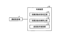
- FIG. 2 is a block diagram showing the configuration of the control device of the continuous casting machine which is an embodiment of the present invention.
- FIG. 3 is a schematic diagram showing a configuration example of the immersion nozzle.
- FIG. 4 is a diagram showing an example of changes in the low flow velocity area due to changes in the magnetic flux density of the electromagnetic stirring magnetic field.
- FIG. 5 is a figure which shows an example of the change of the molten steel surface maximum flow velocity with the change of the magnetic flux density of an electromagnetic stirring magnetic field.
- FIG. 6 is a diagram showing an example of changes in the molten steel surface maximum flow velocity with changes in the magnetic flux density of the electromagnetic stirring magnetic field and the nozzle immersion depth.
- FIG. 7 is a diagram showing an example of a change in the defect mixing rate of the slab depending on whether or not the operating conditions are controlled.
- FIG. 1 is a schematic diagram showing a configuration example of a continuous casting machine to which the present invention is applied.
- a mold 4 is provided vertically below a tundish 3 filled with molten steel 2, and a supply port for the molten steel 2 to the mold 4 is provided at the bottom of the tundish 3.
- the dipping nozzle 5 is provided.
- Molten steel 2 is continuously poured from a tundish 3 into a mold 4, cooled by a mold 4 in which a water-cooled pipe is embedded, and drawn from the lower part of the mold 4 to form a slab.
- the opening degree of the immersion nozzle 5 is adjusted by a sliding gate nozzle or the like (not shown) provided immediately above the immersion nozzle 5 according to the drawing speed.
- the mold 4 is provided with a plurality of temperature sensors on the F surface and the B surface, which are both ends in the thickness direction of the cast slab. Each temperature sensor measures the temperature of the molten steel 2 at each installation position. Further, the mold 4 is provided with a coil (not shown) that generates an electromagnetic stirring magnetic field for rotating the molten metal surface.
- FIG. 2 is a block diagram showing the configuration of the control device of the continuous casting machine which is an embodiment of the present invention.
- a control device 10 of a continuous casting machine is configured by an information processing device such as a computer, and an internal arithmetic processing device such as a CPU (Central Processing Unit) is a computer program.
- an information processing device such as a computer
- an internal arithmetic processing device such as a CPU (Central Processing Unit) is a computer program.
- CPU Central Processing Unit
- the molten steel flow state estimation unit 11 uses a known technique such as the molten steel flow state estimation method described in Patent Document 2 to estimate the flow state of the molten steel 2 in the mold 4 online.
- the molten steel flow state estimation unit 11 uses the physical model such as computational fluid dynamics in consideration of the turbulent flow model and the operating conditions of the continuous casting machine 1 and the measured value of the temperature sensor installed in the mold 4. From this, the flow state of the molten steel 2 in the mold 4 is estimated online.
- Examples of operating conditions of the continuous casting machine 1 include casting width, casting speed, magnetic flux density of electromagnetic stirring magnetic field, immersion depth of the immersion nozzle 5 (nozzle immersion depth), and the like.
- the molten steel flow index calculation unit 12 uses the data on the flow state of the molten steel 2 estimated by the molten steel flow state estimation unit 11 to determine the molten steel flow index that causes impurities to mix into the slab (slab) in the mold 4. Estimate online. Here, as the impurities mixed into the slab, there are inclusions originating from the mold powder.
- the mold powder is a lubricant that is constantly supplied to the upper surface of the molten steel poured into the mold 4 to prevent seizure between the mold 4 and the slab, and also has a heat retaining effect for the molten steel 2.
- the mold powder is in contact with the molten steel 2 in a molten state, and the molten steel 2 is flowing at a certain flow velocity.
- the flow velocity of the molten steel 2 at the contact position with the mold powder is referred to as the surface velocity of the molten steel 2. Therefore, if the surface flow velocity of the molten steel 2 becomes excessively high, the molten powder may be caught in the molten steel 2 to cause inclusion defects.
- the solidification interface flow velocity means the flow velocity of the molten steel in the region near the solidification shell in the mold.
- the molten steel flow index calculation unit 12 calculates the molten steel flow state calculation mesh (width direction and thickness) of the uppermost step (meniscus: height position of molten steel surface) of the mold 4 from the data of the flowing state of the molten steel 2.
- the maximum value of the molten steel flow velocity in all directions is calculated as the molten steel surface maximum flow velocity. Further, the molten steel flow index calculation unit 12 uses the data of the flowing state of the molten steel 2 in the molten steel flowing state calculation mesh (the entire area in the width direction) at predetermined positions in the height direction (casting direction) and the thickness direction of the mold 4. The area of the molten steel flow state calculation mesh in which the molten steel flow velocity is equal to or lower than a predetermined value is calculated.
- the molten steel flow index calculation unit 12 determines the area of the molten steel flow state calculation mesh in which the molten steel flow velocity is equal to or lower than a predetermined value in the entire region in the width direction and in the mold height direction at least 200 mm below the meniscus position. The long sides of the mold are summed up on each side, and the value is taken as the low flow velocity area. Further, the molten steel flow index calculation unit 12 determines the maximum value of the turbulent flow energy in the molten steel flow state calculation mesh (entire region in the width direction and the thickness direction) of the uppermost stage of the mold 4 from the data of the flowing state of the molten steel 2. Calculated as the maximum value of surface turbulence energy.
- the turbulent flow energy is a value that indicates the strength of the turbulence of the flow, and is given based on the magnitude of the deviation from the time average value of the time-varying flow velocity at a certain spatial position.
- the turbulent flow energy is given by the following mathematical formula.
- U is the instantaneous value of the fluid velocity at a certain spatial position
- U ave is the time average value of the fluid velocity at a certain spatial position
- U i is the time average value of the fluid velocity at a certain spatial position. Indicates a shift.
- the low flow velocity area is an effective index because it has an effect of reducing impurities (air bubbles and inclusions) captured by the molten steel 2 in the solidified shell when the molten steel flow at the solidification interface of the slab is fast.
- the flow velocity to be determined as a low flow velocity may be individually determined according to the steel type component, the required quality level, the mold size, etc., and is not fixed. According to the investigation by the present inventors, a value less than 0.05 m/s can be adopted as a criterion for determining a low flow velocity.
- the low flow velocity area is, for example, when the unit area of the molten steel flow state calculation mesh is 1 cm 2 (0.0001 m 2 ), and the unit mesh determined to have a low flow velocity on one side of the long side of the mold is 100 mesh, It is assumed that the low flow velocity area is 0.01 m 2 .
- the appropriate value of the low flow velocity area may be individually determined according to the steel type component, the required quality level, the mold size, etc., and should not be set to a constant value. According to a study by the present inventors, when the required quality level is strict, 0.01 m 2 or less is used, and when the required quality level is not so strict, 0.02 m 2 or less is used as a guideline. Can be adopted.
- the molten steel surface maximum flow velocity is an effective index because it has the effect of reducing the entrainment of mold powder into the molten steel 2 when the molten steel flow on the molten steel surface is slow. Further, the maximum value of the molten steel surface turbulent flow energy is an effective index for the same reason as the molten steel surface maximum flow velocity.
- the operating condition control unit 13 determines the casting speed, the magnetic flux density of the electromagnetic stirring magnetic field, and the nozzle immersion depth according to the molten steel flow index. Control operating conditions such as For example, when the area where the coagulation interface flow velocity is equal to or lower than a predetermined value exceeds a predetermined value, the operating conditions are controlled so that the magnetic flux density of the electromagnetic stirring magnetic field is increased and the electromagnetic stirring force is strengthened. This is because if the flow velocity is further applied to the molten steel in the mold by the electromagnetic stirring force, the molten steel flow velocity will increase even at the position where the solidification interface flow velocity is below a predetermined value.
- the operating condition may be controlled so that the depth of the immersion nozzle is shallow. This is because when the depth of the immersion nozzle is made shallower, the influence of the discharge flow of the molten steel discharged from the immersion nozzle appears more on the molten steel surface side and acts to increase the molten steel flow velocity on the molten steel surface.
- the operating conditions may be controlled so as to increase the depth of the immersion nozzle while increasing the magnetic flux density of the electromagnetic stirring magnetic field.
- the depth of the immersion nozzle is increased, the influence of the molten steel discharge flow discharged from the immersion nozzle is less likely to appear on the molten steel surface side, and acts to reduce the molten steel surface flow velocity and/or the molten steel surface turbulent energy. is there.
- the flow state of the molten steel 2 in the mold 4 changes according to the operating state of the continuous casting machine 1.
- the immersion nozzle 5 having the discharge ports 5a at two positions on the left and right inclusion of alumina or the like adheres to the discharge ports 5a on one side, so that the molten steel in the mold 4 is melted.
- This drift occurs even under the same operating conditions such as the casting width, casting speed, and magnetic flux density of the electromagnetic stirring magnetic field. Therefore, the flow state of molten steel including drift is measured using the measurement value of the temperature sensor installed in the mold 4.
- the molten steel flow index can be accurately estimated online by accurately reproducing.
- the molten steel flow index calculation unit 12 by correcting the calculation conditions in the molten steel flow index calculation unit 12 so as to correspond to the measured values of the temperature sensor installed in the mold 4 and sequentially updating the calculated values, the molten steel flow index can be obtained more accurately online.
- the number of temperature sensors installed, the pitch, and the sampling interval of the measurement values may be set within a range that is possible depending on the environment in which the present invention is implemented. According to the investigation by the present inventors, when the temperature sensors are arranged at a pitch of 50 mm or less and a pitch of 100 mm or less in the casting direction and the width direction, respectively, and measurement values are collected at intervals of 1 second or less, the molten steel flow index calculation The calculation accuracy of the unit 12 is further improved.
- the low flow velocity area was considered as the area where the solidification interface flow velocity is below a predetermined value, but the molten steel flow index is not limited to the flow velocity of the solidification interface itself. If there is a region with a low flow velocity in the molten steel flow (stirring flow) caused by the electromagnetic stirring magnetic field, etc., such a region will adversely affect the capture of bubbles and inclusions at the solidification interface. It can be used as an indicator. As described above, the low flow velocity area is not limited to the solidification interface flow velocity, and various ways of definition are possible.
- the maximum value of the molten steel surface flow velocity and the maximum value of the molten steel surface turbulent flow energy represent the surface state of the molten steel and are associated with the entrainment of mold powder as described above. Therefore, the molten steel flow index is not limited to these maximum values, and can be used as the molten steel flow index by appropriately defining the velocity or flow state of the molten steel surface.
- the present invention was applied in continuous casting of ultra low carbon steel.
- the mold size is 1200 mm in width and 260 mm in thickness, and the casting speed in the steady state is 1.6 m/min.
- the proper range of the low flow velocity area was set to 0.02 m 2 or less, and the proper range of the molten steel surface maximum flow velocity was set to 0.05 to 0.30 m/s for the operation.
- the low flow velocity area calculated during the operation of the continuous casting machine 1 became larger than the appropriate range, so the magnetic flux density of the electromagnetic stirring magnetic field was increased by 5%.
- the molten steel stirring force in the mold 4 became stronger, the solidification interface flow velocity increased, and the low flow velocity area decreased.
- the molten steel surface maximum flow velocity may exceed the appropriate range as shown in FIG. Therefore, the nozzle immersion depth was increased by 30 mm. This is because the discharge flow of the immersion nozzle 5 collides with the copper plate of the casting mold and is reversed, and the flow overlaps the stirring flow to increase the molten steel surface flow velocity. Is smaller, and the molten steel surface flow velocity can be suppressed.
- the operating conditions as shown in FIG. 6, it was possible to control the maximum flow velocity of the molten steel surface within an appropriate range while reducing the low flow velocity area.
- a control method for a continuous casting machine a control device for a continuous casting machine, and a production method for a slab, which are capable of producing a high quality slab.
Landscapes
- Engineering & Computer Science (AREA)
- Mechanical Engineering (AREA)
- Continuous Casting (AREA)
Abstract
L'invention concerne, selon un mode de réalisation, une unité de commande (10) destinée à une machine de coulée continue dotée : d'une unité d'estimation d'état de fluidité d'acier (11) qui met en œuvre une condition de fonctionnement de la machine de coulée continue (1) et des données de température concernant un acier fondu à l'intérieur d'un moule de coulée, pour estimer en direct l'état de fluidité de l'acier fondu à l'intérieur du moule de coulée ; d'une unité de calcul d'indice de fluidité d'acier (12) qui calcule en direct un indice de fluidité d'acier constituant l'origine de l'infiltration d'impuretés dans une brame coulée à l'intérieur du moule de coulée sur la base de l'état de fluidité de l'acier fondu estimé par l'unité d'estimation d'état de fluidité d'acier (11) ; et d'une unité de commande de condition de fonctionnement (13) qui commande l'état de fonctionnement de la machine de coulée continue (1) de sorte que l'indice de fluidité d'acier calculé par l'unité de calcul d'indice de fluidité d'acier (12) se situe dans une plage appropriée.
Priority Applications (8)
| Application Number | Priority Date | Filing Date | Title |
|---|---|---|---|
| PCT/JP2020/004546 WO2020170836A1 (fr) | 2019-02-19 | 2020-02-06 | Procédé de commande pour machine de coulée continue, dispositif de commande pour machine de coulée continue et procédé de fabrication de brame coulée |
| CN202080013723.9A CN113423521B (zh) | 2019-02-19 | 2020-02-06 | 连续铸造机的控制方法、连续铸造机的控制装置及铸片的制造方法 |
| JP2020532835A JP6981551B2 (ja) | 2019-02-19 | 2020-02-06 | 連続鋳造機の制御方法、連続鋳造機の制御装置、及び鋳片の製造方法 |
| BR112021015867-7A BR112021015867B1 (pt) | 2019-02-19 | 2020-02-06 | Método e dispositivo de controle para máquina de lingotamento contínuo e método de fabricação para peça fundida |
| US17/422,674 US11890671B2 (en) | 2019-02-19 | 2020-02-06 | Control method for continuous casting machine, control device for continuous casting machine, and manufacturing method for casting |
| KR1020217026128A KR102695836B1 (ko) | 2019-02-19 | 2020-02-06 | 연속 주조기의 제어 방법, 연속 주조기의 제어 장치 및, 주편의 제조 방법 |
| EP20759007.6A EP3928890B1 (fr) | 2019-02-19 | 2020-02-06 | Procédé de commande pour machine de coulée continue, dispositif de commande pour machine de coulée continue et procédé de fabrication de pièce coulée |
| TW109105112A TWI743686B (zh) | 2019-02-19 | 2020-02-18 | 連續鑄造機之控制方法、連續鑄造機之控制裝置、以及鑄片之製造方法 |
Applications Claiming Priority (2)
| Application Number | Priority Date | Filing Date | Title |
|---|---|---|---|
| JP2019-027374 | 2019-02-19 | ||
| JP2019027374 | 2019-02-19 |
Publications (1)
| Publication Number | Publication Date |
|---|---|
| WO2020170563A1 true WO2020170563A1 (fr) | 2020-08-27 |
Family
ID=72145058
Family Applications (1)
| Application Number | Title | Priority Date | Filing Date |
|---|---|---|---|
| PCT/JP2019/048374 Ceased WO2020170563A1 (fr) | 2019-02-19 | 2019-12-11 | Procédé de commande destiné à une machine de coulée continue, dispositif de commande destiné à une machine de coulée continue, et procédé de fabrication de brame |
Country Status (3)
| Country | Link |
|---|---|
| KR (1) | KR102695836B1 (fr) |
| CN (1) | CN113423521B (fr) |
| WO (1) | WO2020170563A1 (fr) |
Citations (2)
| Publication number | Priority date | Publication date | Assignee | Title |
|---|---|---|---|---|
| JP2011206845A (ja) * | 2010-03-10 | 2011-10-20 | Jfe Steel Corp | 鋼の連続鋳造方法および鋼板の製造方法 |
| JP2017159363A (ja) * | 2016-03-02 | 2017-09-14 | Jfeスチール株式会社 | 溶鋼の流動状態推定方法、流動状態推定装置、溶鋼の流動状態のオンライン表示装置および鋼の連続鋳造方法 |
Family Cites Families (12)
| Publication number | Priority date | Publication date | Assignee | Title |
|---|---|---|---|---|
| US5884685A (en) * | 1995-03-29 | 1999-03-23 | Nippon Steel Corporation | Quality prediction and quality control of continuous-cast steel |
| JPH10305353A (ja) | 1997-05-08 | 1998-11-17 | Nkk Corp | 鋼の連続鋳造方法 |
| WO2000051762A1 (fr) * | 1999-03-02 | 2000-09-08 | Nkk Corporation | Procede et dispositif permettant, en coulee continue, de predire et de reguler la configuration d'ecoulement de l'acier en fusion |
| JP3607882B2 (ja) * | 2000-07-19 | 2005-01-05 | 新日本製鐵株式会社 | 連続鋳造鋳型内全域の凝固シェル厚、溶鋼流速、鋳片品質センシング方法及びその装置。 |
| JP4407260B2 (ja) * | 2003-11-28 | 2010-02-03 | Jfeスチール株式会社 | 鋼の連続鋳造方法 |
| KR20120107928A (ko) * | 2009-08-31 | 2012-10-04 | 아이워크, 아이엔씨. | 의족 보철 또는 지지대를 이용하는 기립 시퀀스의 구현 |
| JP4569715B1 (ja) * | 2009-11-10 | 2010-10-27 | Jfeスチール株式会社 | 鋼の連続鋳造方法 |
| US20110174457A1 (en) * | 2010-01-18 | 2011-07-21 | Evraz Inc. Na Canada | Process for optimizing steel fabrication |
| JP2014032719A (ja) * | 2012-08-02 | 2014-02-20 | Sony Corp | 記録再生装置、レーザ駆動パルス調整方法、プログラム |
| JP5935837B2 (ja) * | 2014-07-07 | 2016-06-15 | Jfeスチール株式会社 | 溶鋼の流動状態推定方法及び流動状態推定装置 |
| DE102014223750A1 (de) * | 2014-11-20 | 2016-05-25 | Carl Zeiss Smt Gmbh | Projektionsbelichtungsanlage mit mindestens einem Manipulator |
| RU2712040C2 (ru) * | 2015-02-12 | 2020-01-24 | Конинклейке Филипс Н.В. | Одновременная оценка параметров дыхания путем областной аппроксимации параметров дыхания |
-
2019
- 2019-12-11 WO PCT/JP2019/048374 patent/WO2020170563A1/fr not_active Ceased
-
2020
- 2020-02-06 CN CN202080013723.9A patent/CN113423521B/zh active Active
- 2020-02-06 KR KR1020217026128A patent/KR102695836B1/ko active Active
Patent Citations (2)
| Publication number | Priority date | Publication date | Assignee | Title |
|---|---|---|---|---|
| JP2011206845A (ja) * | 2010-03-10 | 2011-10-20 | Jfe Steel Corp | 鋼の連続鋳造方法および鋼板の製造方法 |
| JP2017159363A (ja) * | 2016-03-02 | 2017-09-14 | Jfeスチール株式会社 | 溶鋼の流動状態推定方法、流動状態推定装置、溶鋼の流動状態のオンライン表示装置および鋼の連続鋳造方法 |
Also Published As
| Publication number | Publication date |
|---|---|
| CN113423521B (zh) | 2023-12-01 |
| KR102695836B1 (ko) | 2024-08-14 |
| KR20210116577A (ko) | 2021-09-27 |
| CN113423521A (zh) | 2021-09-21 |
Similar Documents
| Publication | Publication Date | Title |
|---|---|---|
| KR101047826B1 (ko) | 제어 시스템, 컴퓨터 프로그램 제품, 장치 및 방법 | |
| JP2009183977A (ja) | 連続鋳造における鋳片の軽圧下方法 | |
| Thomas | Fluid flow in the mold | |
| WO2020170563A1 (fr) | Procédé de commande destiné à une machine de coulée continue, dispositif de commande destiné à une machine de coulée continue, et procédé de fabrication de brame | |
| JPH06264B2 (ja) | 連続鋳造における湯面レベル制御方法 | |
| WO2020170836A1 (fr) | Procédé de commande pour machine de coulée continue, dispositif de commande pour machine de coulée continue et procédé de fabrication de brame coulée | |
| KR20120044433A (ko) | 몰드내 용강 유동 편류 저감장치 및 이를 이용한 저감방법 | |
| KR101400044B1 (ko) | 연주 공정에서의 주조속도 제어 방법 | |
| KR100663916B1 (ko) | 연속 주조 방법 | |
| TWI743686B (zh) | 連續鑄造機之控制方法、連續鑄造機之控制裝置、以及鑄片之製造方法 | |
| CN1330439C (zh) | 控制系统,计算机程序产品,装置和方法 | |
| JP4893068B2 (ja) | 連続鋳造鋳片の凝固完了位置制御方法及び装置並びに連続鋳造鋳片の製造方法 | |
| JP4972776B2 (ja) | 鋳型内溶鋼の流動制御方法及び連続鋳造鋳片の表面品質判定方法 | |
| KR102257856B1 (ko) | 연속주조공정의 용강유동 제어장치 및 이를 이용한 용강유동 제어방법 | |
| KR101368351B1 (ko) | 연속주조 시 응고쉘 두께 예측 방법 | |
| RU2775264C1 (ru) | Способ управления для машины непрерывного литья, устройство управления для машины непрерывного литья и способ изготовления отливки | |
| JP2962788B2 (ja) | 連続鋳造鋳型内における溶鋼の偏流制御方法 | |
| BR112021015867B1 (pt) | Método e dispositivo de controle para máquina de lingotamento contínuo e método de fabricação para peça fundida | |
| RU2763994C1 (ru) | Устройство и способ управления непрерывной разливкой | |
| JPH09182943A (ja) | 鋼の連続鋳造方法 | |
| KR20130013738A (ko) | 연주기 몰드의 탕면 변동 측정장치 및 방법 | |
| KR101675670B1 (ko) | 연속주조 공정의 유동 제어 장치 및 방법 | |
| JPH05277681A (ja) | 連続鋳造方法 | |
| KR20140017144A (ko) | 연속주조시 응고쉘의 수축량 예측 방법 | |
| KR20140056713A (ko) | 몰드 직하 응고두께 제어방법 |
Legal Events
| Date | Code | Title | Description |
|---|---|---|---|
| 121 | Ep: the epo has been informed by wipo that ep was designated in this application |
Ref document number: 19915837 Country of ref document: EP Kind code of ref document: A1 |
|
| NENP | Non-entry into the national phase |
Ref country code: DE |
|
| 122 | Ep: pct application non-entry in european phase |
Ref document number: 19915837 Country of ref document: EP Kind code of ref document: A1 |
|
| NENP | Non-entry into the national phase |
Ref country code: JP |