WO2020170765A1 - Gabarit de fixation pour soudage par friction linéaire et procédé de soudage par friction linéaire - Google Patents
Gabarit de fixation pour soudage par friction linéaire et procédé de soudage par friction linéaire Download PDFInfo
- Publication number
- WO2020170765A1 WO2020170765A1 PCT/JP2020/003710 JP2020003710W WO2020170765A1 WO 2020170765 A1 WO2020170765 A1 WO 2020170765A1 JP 2020003710 W JP2020003710 W JP 2020003710W WO 2020170765 A1 WO2020170765 A1 WO 2020170765A1
- Authority
- WO
- WIPO (PCT)
- Prior art keywords
- linear friction
- friction welding
- joined
- fixing
- fixing jig
- Prior art date
- Legal status (The legal status is an assumption and is not a legal conclusion. Google has not performed a legal analysis and makes no representation as to the accuracy of the status listed.)
- Ceased
Links
Images






Classifications
-
- B—PERFORMING OPERATIONS; TRANSPORTING
- B23—MACHINE TOOLS; METAL-WORKING NOT OTHERWISE PROVIDED FOR
- B23K—SOLDERING OR UNSOLDERING; WELDING; CLADDING OR PLATING BY SOLDERING OR WELDING; CUTTING BY APPLYING HEAT LOCALLY, e.g. FLAME CUTTING; WORKING BY LASER BEAM
- B23K20/00—Non-electric welding by applying impact or other pressure, with or without the application of heat, e.g. cladding or plating
- B23K20/12—Non-electric welding by applying impact or other pressure, with or without the application of heat, e.g. cladding or plating the heat being generated by friction; Friction welding
Definitions
- the present invention relates to a linear friction welding fixing jig used for fixing a material to be welded in linear friction welding, and a linear friction welding method using the linear friction welding fixing jig.
- LFW Linear Friction Welding
- FSW Friction Stir Welding
- Patent Document 1 Japanese Patent Laid-Open No. 2018-122343
- a first step in which one member is brought into contact with the other member to form a bonded interface, and pressure is applied substantially perpendicularly to the bonded interface.
- the second step of repeatedly sliding one member and the other member on the same locus under the condition of applying the burrs from the interface to be bonded, and stopping the sliding to form the bonding surface.
- a characteristic linear friction welding method is disclosed, and it is possible to form a good joint even with a thin plate.
- the materials to be bonded are shaken (moved or tilted), and the bonding pressure and sliding force cannot be efficiently converted into the bonding temperature.
- the joining results obtained from the above may vary.
- the material to be joined is a thin plate, the problem becomes remarkable. That is, it is difficult to industrially apply linear friction welding in a situation where the materials to be welded cannot be reliably fixed.
- a substantially rectangular fixing hole provided in a direction substantially perpendicular to the side surface of the vibrating portion, and the fixing hole
- a fixing mechanism including a pressing portion that can move in one direction is generally used. Since the fixing mechanism changes the dimension in the fixing hole by moving the pressing portion and presses and fixes the material to be welded inserted in the fixing hole, in the method of fixing the material to be welded using this fixing mechanism, Only the pressing force applied from the pressing portion and the reaction force applied from the side surface of the fixing hole facing the pressing portion act to fix the materials to be joined.
- the fixing hole is formed with a large size so that the materials to be welded of various sizes can be inserted, there is no portion that abuts the material to be welded in the direction substantially orthogonal to the moving direction of the pressing portion. It is obvious that not only positioning of the materials to be joined in the fixing holes becomes difficult but also blurring is induced during joining, and there is still room for improvement.
- the present invention enables the material to be welded to be simply and surely fixed to the linear friction welding apparatus, and enables highly reproducible linear friction welding corresponding to the welding conditions.
- An object of the present invention is to provide a fixing jig for linear friction welding and a linear friction welding.
- the present invention is A first member provided with a pressed surface that receives a pressing force from a bonded material fixing portion of a linear friction welding device, and a valley formed by arranging two inclined surfaces opposite to each other on the opposite side of the pressed surface.
- a second member having contact surfaces that contact the inclined surface at both ends, Consisting of two said first members and two said second members, A fixing jig for linear friction welding, which is characterized by:
- the inclined surface of the first member and the contact surface of the second member are substantially parallel to each other.
- the material to be welded is uniquely and It is possible to accurately position and securely fix in a short time.
- the materials to be joined are held in contact with one of the second members and the other second member over a wide area and are sandwiched by these members, the blur in the height direction (sliding direction) due to sliding during joining is caused. Can be effectively suppressed.
- one material to be welded and the other material to be welded can be accurately brought into contact with each other without displacement and angular deviation before welding, and there is no gap over the entire area. Can form a good bonding interface. That is, when both materials to be welded are repeatedly slid on the same locus by the linear friction welding device, a substantially uniform temperature rise occurs over the entire joining interface, so that the joining temperature can be accurately controlled.
- the blurring (movement or inclination) of the joined materials due to the improper fixing is suppressed, and the joining pressure and the sliding force are efficiently joined. Can be converted to temperature. Therefore, it is possible to reduce the variation between the set joining condition and the joining result.
- the second member has a substantially truncated pyramid shape.
- the contact surface of the second member and the slope of the first member have the same angle, and the vertical dimension and the horizontal dimension are different.
- it can be used corresponding to a material to be joined having a certain size width.
- it is possible to prolong the life of the linear friction welding fixing jig without being repeatedly given the thermal influence during welding on only a part thereof.
- the area of the second member that contacts the material to be welded is larger than the pressed surface.
- the pressing force from the linear friction welding device is converted by approximately 90°, so that the area of the second member that abuts the material to be welded is larger than the surface to be pressed.
- the materials to be joined can be fixed more reliably and efficiently.
- the area of the second member is preferably twice or more the area of the pressed surface, more preferably three times or more, and most preferably four times or more.
- the first member and/or the second member is tool steel, heat resistant steel, cemented carbide, cermet, nickel base alloy, cobalt base alloy and titanium alloy. It is desirable to be formed of any one of the above materials. By using these materials for the first member and/or the second member, wear and shape change due to repeated use can be suppressed, and sufficient strength and dimensional accuracy can be ensured against temperature rise during joining. can do.
- the first member and/or the second member is preferably made of ceramics.
- the present invention is A method for joining one joined material and the other joined material, Fixing the one material to be joined and/or the other material to be joined to the linear friction welding device by the linear friction welding fixing jig according to any one of claims 1 to 5; A linear friction welding method is also provided.
- one of the materials to be welded and/or the other material to be welded is fixed to the linear friction welding apparatus using the fixing jig for linear friction welding of the present invention. And the material to be joined can be securely fixed. As a result, the stress applied from the linear friction welding device can be transmitted to the material to be welded without waste, and linear friction welding can be performed according to the set welding conditions (pressing force and vibration force on the material to be welded). You can
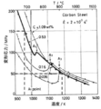
- the second step, And a third step of forming a bonded interface by stopping the sliding It is preferable that the pressure is set to be equal to or higher than the yield stress and equal to or lower than the tensile strength of the one joined material and/or the other joined material at a desired joining temperature.
- the welding temperature is controlled by setting the pressure during linear friction welding to a yield stress of one member and/or the other member at a desired joining temperature and equal to or less than the tensile strength. It has become clear that you can.
- the pressure during linear friction welding is made equal to or higher than the yield stress of the materials to be welded, discharge of burrs from the interface to be welded is started, and if the pressure is increased up to the tensile strength, the burrs will be discharged. It will be accelerated. Similar to the yield stress, the tensile strength at a specific temperature is substantially constant depending on the materials to be joined, so that the joining temperature corresponding to the set pressure can be realized.
- the pressure during linear friction welding it is preferable to set the pressure during linear friction welding to the yield stress of one member and/or the other member at a desired welding temperature.
- the discharge of burr starts at the moment when the pressure reaches the yield stress, which is more accurate than when the pressure is set to a higher value (with the tensile strength as the upper limit).
- a bonding temperature can be realized.
- the one joined material and/or the other joined material is a thin plate having a plate thickness of 3 mm or less.
- the applied pressure during linear friction welding is set to be equal to or higher than the yield stress of the thin plate (material to be welded) at the desired welding temperature, so that the heated and softened region is promptly discharged as burr. It is possible to prevent the softened portion (high temperature portion) from unnecessarily expanding due to heat conduction of frictional heat. In this case, the temperature at the position away from the bonded interface is lower than the temperature in the vicinity of the bonded interface (bonding temperature), and plastic deformation does not occur under the applied pressure. As a result, even if the plate thickness is 3 mm or less, its shape can be maintained during linear friction welding.
- the fixing tool for linear friction welding which fixes a to-be-joined material with respect to a linear friction welding apparatus simply and reliably and can implement highly reproducible linear friction welding corresponding to a joining condition, and A linear friction bond can be provided.
- FIG.3(a) is a side view of the 1st member 3 which carried out the front view of the end surface of the 1st member 3
- FIG.3(b) is FIG. 3A is a front view of the first member 3 in which a part of the arrow A in FIG. 3A is cross-sectionally viewed
- FIG. 3C is a bottom view of the first member 3 that is viewed in the arrow B in FIG. ..
- FIG.4(a) is a front view of the 2nd member 5
- FIG.4(b) shows the arrow C in FIG.4(a) second.
- FIG. 5(a) is a perspective view
- FIG. 5(b) is a side view.
- FIG. 6(a) is a perspective view
- FIG. 6(b) is a side view. ..
- FIG.7(a) is a perspective view
- FIG.7(b) is a side view
- FIG.8(a) is a schematic diagram which shows a mode that the fixing preparation body 101 is inserted in the fixing hole 52
- FIG.8(b) is a schematic view showing pressing of a material 53 to be joined by the linear friction joining fixing jig 1.
- FIG.9(a) is a perspective view
- FIG.9(b) is a side view
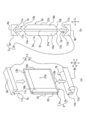
- FIG. 1 is a schematic diagram showing a situation during linear friction welding
- FIG. 2 is a schematic diagram showing an outline of a fixing jig 1 for linear friction welding according to the present embodiment.
- the direction in which the bonding pressure is applied is defined as X
- the direction substantially perpendicular to X and the sliding direction is defined as Y
- the sliding direction is defined as Z.
- linear friction welding the materials to be welded are brought into contact with each other in a linear motion while applying a predetermined welding pressure from opposite directions, and frictional heat generated at this time is used as a main heat source.
- Solid phase bonding The main methods used for linear friction welding here are a preliminary step in which one material to be joined and the other material to be joined are fixed to the linear friction welding device, and both materials are brought into contact with each other. And a second step of repeatedly sliding both materials to be joined on the same locus at the formed joint interface, and stopping the sliding at a predetermined timing to form a joint. And a third step.
- the fixing tool 1 for linear friction joining of the present embodiment includes two second members 5 (one second member 5a and the other second member 5b) that directly abut the joined material 53.
- a jig constituted by two first members 3 (one first member 3a and the other first member 3b) that sandwich the second member 5 between the first member 3 and the first member 3b.
- Each of these members is arranged between the device 51 and the device for use.
- the improvement of the joining preparation makes it possible to prevent the joined material 53 from being shaken due to improper fixing, so that the joining temperature can be easily controlled during the second step and the joined object can be stopped during the sliding stop in the third step. It is possible to prevent an inclination or the like from occurring between the materials 53. That is, the fixing jig 1 for linear friction welding according to the present embodiment provides a plurality of suitable effects for linear friction welding.
- the linear friction welding device 51 used in the present embodiment includes a fixing hole 52 into which the end of the material to be welded 53 opposite to the joining surface 61 is inserted into the vibrating portion, and a lower end (or an upper end) of the fixing hole 52.
- a fixing mechanism 55 for the material 53 to be joined which comprises a pressing portion 54 that moves up and down in the direction Z, and the material 53 to be joined inserted in the fixing hole 52 is pressed and fixed in the direction Z by the pressing portion 54.
- the pressing direction for fixing the joined material 53 is not limited to the above, and the direction Y may be adopted, for example.
- FIGS. 3 and 4. are diagrams showing the structure of the first member 3, and FIG. 3A is a side view of the first member 3 in which the end face of the first member 3 is viewed from the front.
- 3(b) is a front view of the first member 3 in which a part of the arrow A in FIG. 3(a) is cross-sectionally viewed, and FIG. 3(c) is an arrow in FIG. 3(a).
- 4(a) and 4(b) are views showing the structure of the second member 5
- FIG. 4(a) is a front view of the second member 5
- FIG. 4(b) is It is a side view of the second member 5 which shows the arrow C in FIG.
- the first member 3 is a valley formed by arranging a pressed surface 9 that receives a pressing force from the linear friction welding device 51 and two inclined surfaces 11 so as to face each other. And a valley portion 7 is formed on the opposite side of the pressed surface 9 in the pressing force application direction (downward in the direction Z in FIG. 3A). ..
- a substantially smooth pressed surface that abuts the pressing portion 9 of the linear friction welding device 51 or the upper side surface of the fixing hole 52 that faces the pressing portion 9. 9 and a valley portion 7 formed by two inclined surfaces 11 which are downwardly inclined in the direction Z and toward both sides in the direction Y from approximately the center of the pressed surface 9 and the direction Y of the pressed surface 9. It has a side surface shape composed of a vertical plane that connects both ends and both ends of the two inclined surfaces 11 in the direction Y in the direction Z (in particular, refer to FIG. 3A). It is a substantially columnar body extruded by a predetermined size (see particularly FIGS. 3B and 3C).
- the vicinity of the apex (the bottom of the valley 7) formed by the two inclined surfaces 11 may be formed in an arc shape in the range of 2.5R to 5R to improve the cleaning property and the maintainability.
- the side surfaces of both ends of the first member 3 are formed parallel and smooth with respect to the direction Z, but depending on the aspect of the linear friction welding device 51 and the shape and size of the material 53 to be welded. Different shapes may be adopted as appropriate.
- the angle ⁇ 1 of the inclined surface 11 with respect to the direction Z is preferably set in the range of 30 to 60 degrees in order to ensure good sliding between the first member 3 and the second member 5 described later. Further, for the same reason, it is preferable that the inclined surface 11 has a surface roughness that suppresses the generation of frictional resistance without unevenness.
- the substantially straight inclined surface 11 without distortion is adopted, but it may be an arc having a gentle curvature, for example.
- the second member 5 is formed with contact surfaces 13 that contact the inclined surface 11 of the first member 3 at both ends.
- the abutting inclined surface 11 and the abutting surface 13 are substantially parallel to each other.
- a substantially rectangular fixing surface 15 that faces the direction Y and directly abuts on the joined material 53, and both end portions of the fixing surface 15 in at least the direction Z.
- the member is composed of a slope 19 that is inclined in the opposite direction to the fixed surface 15 and a parallel surface 21 that is parallel to the fixed surface 15 and faces the opposite direction.
- the angle ⁇ 2 of the contact surface 13 with respect to the fixed surface 15 is in the range of 30 to 60 degrees and is the same as the angle ⁇ 1 of the inclined surface 11 with respect to the direction Z (vertical surface) described above, and is good with the first member 3 described above. It is desirable to secure a good slide. Further, like the surface of the inclined surface 11, the contact surface 13 preferably has a surface roughness that suppresses the generation of frictional resistance without unevenness.
- the second member 5 has a substantially truncated pyramid shape.
- the second member 5 of the present embodiment is provided with the slopes 19 at both ends in the direction X as described above, and is formed into a substantially quadrangular truncated pyramid shape as a whole.
- the material 53 to be bonded can be fixed up to the vicinity of the bonding surface 61, and more stable bonding can be performed.
- the angle of the inclined surface 19 with respect to the fixed surface 15 is the same as the angle ⁇ 2 of the inclined surface 13 with respect to the fixed surface 15, the inclined surface 19 is slidably engaged with the inclined surface 11 of the first member 3 like the contact surface 13. Can be stopped. Therefore, for example, if the second member 5 is formed so that the dimension in the Z direction and the dimension in the X direction are different from each other, depending on the size of the material 53 to be bonded, the material 53 to be bonded 53 can be made more from the Z direction or the X direction of the second member 5. It becomes possible to select and use a direction suitable for fixing, and it is possible to deal with the joined material 53 having a certain size width with one linear friction joining fixing jig 1.
- the first member 3 and/or the second member 5 is preferably formed of any material of tool steel, heat resistant steel, cemented carbide, cermet, nickel base alloy, cobalt base alloy and titanium alloy.
- the first member 3 and the second member 5 described above are required not only to have high strength and wear resistance, but also because they are used for joining the materials 53 to be joined of various metal materials, heat influence from the vicinity of the joining surface 61 Highly likely to receive.
- the inclined surface 11, the contact surface 13, the inclined surface 19 and the like are slidably locked to each other, it is necessary to process them to have a corresponding surface roughness.
- first member 3 and/or the second member 5 is formed of any one of tool steel, cemented carbide, cermet, nickel-based alloy and cobalt-based alloy, mechanical properties are sufficiently secured and during bonding. It can withstand the heat effect of. In addition, precision processing can be performed relatively easily.
- FIGS. 5 to 7 are diagrams showing a method of bringing the second member 5 into contact with the material 53 to be joined, FIG. 5(a) is a perspective view, and FIG. 5(b) is a side view. Is.
- FIGS. 6A and 6B are diagrams showing a method of bringing the first member 3 into contact with the second member 5 that has come into contact with the material 53 to be joined, and FIG.
- FIG. 6A is a perspective view.
- FIG. 6B is a side view.
- 7(a) and 7(b) are diagrams showing the fixing jig 1 for linear friction welding and the material 53 to be joined after abutting, and FIG. 7(a) is a perspective view and FIG. b) is a side view.
- the second member 5 of the linear friction welding fixing jig 1 is brought into contact with the workpiece 53.
- the two surfaces facing the direction Y of the material 53 to be joined are the first surface 57 and the second surface 59, and the member contacting the first surface 57 is in contact with one of the second member 5a and the second surface.
- the member is the other second member 5b.
- the material 53 to be welded and the fixing jig 1 for linear friction welding maintain the illustrated directionality (direction X, direction Y, and direction Z) unless otherwise specified in the text.
- the second surface 5a is brought into contact with the material 53 to be bonded while the fixed surface 15a is opposed to the first surface 57 of the material 53 to be bonded, and the fixed surface 15b is opposed to the second surface 59 while the other is opposed to the second surface 59.
- the second member 5b is brought into contact with the material 53 to be joined.
- the bonding surface 61 of the material 53 to be bonded is projected in the direction Y by a predetermined amount from the slopes 19a and 19b.
- the protrusion amount may be appropriately determined according to the size of the material 53 to be bonded, the bonding conditions, and the like.
- the first member 3 is brought into contact with the material 53 and the second member 5 that have been brought into contact with each other in the above procedure.
- the member to be brought into contact with the upper side of the joined material 53 and the second member 5 in the direction Z is one first member 5a, and the member to be brought into contact with the lower side is the other second member 5b.
- the valley portion 7a of the one first member 3a is opposed to the contact surface 13a of the one second member 5a and the contact surface 13b of the other second member 5b facing upward in the direction Z.
- the abutting surface 13a and the abutting surface 13b are brought into contact with the two inclined surfaces 11a forming 7a, respectively.
- the valley portion 7b of the other first member 3b is opposed to the contact surface 13a of the one second member 5a and the contact surface 13b of the other second member 5b facing downward in the direction Z.
- the abutting surface 13a and the abutting surface 13b are brought into contact with and locked by the two inclined surfaces 11b forming the valley portion 7b.
- the joined material 53 is supported by being abutted in the direction Y by the one second member 5a and the other second member 5b, and further, the one second member 5a and the other second member. 5b above and below in the direction Z, the substantially first fixing preparation body 101 that is locked by the first member 3a on one side and the first member 3b on the other side, and is made up of the joined material 53, the first member 3, and the second member 5. (See especially FIGS. 7A and 7B).
- FIGS. 8A and 8B are views showing a method of fixing the fixing preparation body 101 by the linear friction welding device 51
- FIG. 8A shows a state in which the fixing preparation body 101 is inserted into the fixing hole 52.
- FIG.8(b) is a schematic diagram which shows the pressing of the to-be-joined material 53 by the fixing jig 1 for linear friction welding.
- the fixing preparation body 101 configured by the above procedure is inserted into the fixing hole 52 of the fixing mechanism 55 included in the linear friction welding device 51. More specifically, the fixing preparation body 101 is inserted into the fixing hole 52 with the opposite side of the joining surface 61 facing the fixing hole 52, and the pressed surface 9a of the one first member 3a is fixed to the fixing hole 52. Abuts on the upper end in the direction Z.
- the pressing portion 54 provided in the fixing mechanism 55 is moved from the lower side to the upper side in the direction Z to press the fixing preparation body 101 inserted into the fixing hole 52.
- the fixing preparation body 101 is pressed between the upper end of the fixing hole 52 and the pressing portion 54, and the pressed surface 9a of the one first member 3a and the other first member 3b.
- the pressed surface 9b receives the pressing force P1 acting in the direction Z.
- the pressing force P1 presses the first member 3a on one side and the first member 3b on the other side toward the material 53 to be bonded, while the inclined surface 11a of the first member 3a on one side and the inclined surface 11b of the first member 3b on the other side. Via the contact surface 13a of the one second member 5a and the contact surface 13b of the other second member 5b. At the time of the transmission, a part of the pressing force P1 changes the action direction and generates a pressing force P2 that acts on the joined material 53 in a substantially oblique direction.
- the first member 3 and the second member 5 are locked to each other by abutting the slanted inclined surface 11 and the abutting surface 13, so that the first member 3a located on the upper side.
- the other first member 3b positioned below receives the pressing force P1 and the pressing force P2, which face each other, and is pressed in the direction Z toward the joined material 53 side, whereby the one second member 5a.
- the other second member 5b is substantially compressed, and the contact surface 13a and the contact surface 13b that are in contact with the two inclined surfaces 11a that form the valley portion 7a are upward and in the direction Z along their inclinations.
- the contact surface 13a and the contact surface 13b which are slid to the joined material 53 side of Y and contact the two inclined surfaces 11b forming the valley portion 7b, are downward in the direction Z along their own inclinations. Further, each slides in the direction Y toward the joined material 53, and the pressing force P3 acting in the direction Y acts on the joined material 53.
- the force applied from the fixing mechanism 55 to the fixing preparation 101 in the direction Z from above to below and from below to above is in the same direction.
- the pressing force P1 acting (two directions up and down in the direction Z with respect to the material 53 to be joined), and the pressing force P2 acting in a substantially oblique direction when transmitting the pressing force P1 from the first member 3 to the second member 5
- the material to be welded 53 pressed by the force in the eight directions is automatically and accurately positioned in the approximate center of the direction Y by the action of the pressing force P3, and further, in the directions X, Y, and by the action of all the pressing forces P1 to P3.
- the upper and lower end surfaces of the joined material 53 in the direction Z are not in contact with either the first member 3 or the second member 5, but the first surface 57 and the second surface 59 of the joined material 53 are one of the first surface.
- the fixing surface 15a of the second member 5a and the fixing surface 15b of the other second member 5b are in contact with each other over a wide area, and the end surface of the material 53 to be bonded opposite to the bonding surface 61 is directed in the direction X inside the fixing hole 52.
- the material 53 to be joined is sandwiched between the second member 5a on one side and the second member 5b on the other side in a wide area while being abutted against each other. It is possible to preferably prevent the shake in the direction Z to be performed.
- the second member 5 can be used while changing the direction of the second member 5 as appropriate, so that the linear friction welding fixing jig 1 does not have a repeated thermal effect on only a part thereof. The life can be properly extended.
- the material 53 to be welded (hereinafter, the reference numeral of the material to be welded will be omitted for convenience of description) is positioned and reliably fixed by the linear friction welding fixing jig 1, one of the materials to be welded and the other
- the materials to be welded can be accurately brought into contact with each other without displacement and distortion, and a good welding interface with no gap can be formed over the entire area. That is, when both the materials to be welded are repeatedly slid on the same locus by the linear friction welding device 51, a substantially uniform temperature rise occurs over the entire welding interface, so that the welding temperature can be accurately controlled.
- the sliding is repeated along the same locus while applying the joining pressure. Even during bonding, there is no blurring (movement or inclination) of the materials to be bonded due to improper fixing, and the bonding pressure and sliding force can be efficiently converted to the bonding temperature. Therefore, it is possible to preferably reduce the variation in the joining condition and the joining result due to the fixing condition of the materials to be joined.
- FIG. 9(a) and 9(b) are views showing the structure of another fixing jig 1001 for linear friction joining, FIG. 9(a) is a perspective view, and FIG. 9(b) is a side view. is there.
- the other fixing jig 1001 for linear friction welding has an optimized shape so that it can be used to fix the substantially cylindrical material 1053 to be welded.
- the linear friction welding fixing jig 1001 is also a jig including two first members 1003 and two second members 1005 as in the linear friction welding fixing jig 1 described above.
- the fixed surface 1015 of 1005 is provided with a recess 1007 having a substantially curved surface that matches the side surface shape of the material 1053 to be joined.
- the radius of the recess 1007 may be substantially the same as the radius of the material 1053 to be bonded, and may be formed in the second member 1005 to a depth such that both fixing surfaces 1015 do not abut when the material 1053 to be bonded is fixed. preferable. In addition, it is desirable that the recesses 1007 be formed so as not to be displaced with respect to each other at substantially the center in the direction Z of both the second members 1005.
- FIG. 10 shows an external photograph of the linear friction welding device.
- the yield stress is about 150 MPa.
- the pressure applied during linear friction welding was 250 MPa, which was higher than 150 MPa, the frequency of vibration was 15 Hz, and the amplitude was 2 mm to obtain a bonded body.
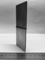
- FIG. 12 shows an external view photograph of the execution bonded body.
- FIG. 14 shows a state in which the material to be welded is fixed to the linear friction welding device.
- the stress of the linear friction welding device is applied only from above the welded device, but the stress is transmitted from the first member arranged above and below the welded material to the second member, and the welded material is strong from both sides. It is fixed to.
- Fig. 15 shows a macro photograph of a cross section in the vicinity of the bonding interface of the obtained bonded structure. No defects were found at the joint interface, indicating that a good joint was obtained.
- FIG. 16 shows a state in which the material to be welded is fixed to the linear friction welding device. Pads are arranged on the left and right of the materials to be joined, and the pressing force from the device is applied only from above the materials to be joined.
- Fig. 17 shows a cross-sectional macro photograph of the vicinity of the joint interface of the obtained comparative joint.
- the bonding conditions are the same as in the example, defects are formed at the bonding interface. The results suggest that the pressure and the vibration force applied during linear friction welding were not directly transmitted to the materials to be welded.
Landscapes
- Engineering & Computer Science (AREA)
- Mechanical Engineering (AREA)
- Pressure Welding/Diffusion-Bonding (AREA)
Abstract
La présente invention concerne un gabarit de fixation pour soudage par friction linéaire et un procédé de soudage par friction linéaire avec lesquels il est possible de fixer facilement et de manière fiable un matériau de soudage à un dispositif de soudage par friction linéaire et d'effectuer un soudage par friction linéaire adapté aux conditions de soudage avec une reproductibilité élevée. Ce gabarit de fixation pour soudage par friction linéaire est caractérisé en ce qu'il comprend : un premier élément ayant une surface pressée qui reçoit la force de pression provenant d'une unité de fixation de matériau de soudage du dispositif de soudage par friction linéaire et une partie vallée qui est formée par deux surfaces inclinées disposées l'une en face de l'autre sur le côté opposé par rapport à la surface pressée; et un second élément ayant, sur ses deux extrémités, des surfaces de contact respectives pour entrer en contact avec les surfaces inclinées, le gabarit de fixation étant constitué de deux premiers éléments et de deux seconds éléments.
Priority Applications (1)
| Application Number | Priority Date | Filing Date | Title |
|---|---|---|---|
| JP2021501801A JP7374512B2 (ja) | 2019-02-22 | 2020-01-31 | 線形摩擦接合用固定治具及び線形摩擦接合方法 |
Applications Claiming Priority (2)
| Application Number | Priority Date | Filing Date | Title |
|---|---|---|---|
| JP2019030186 | 2019-02-22 | ||
| JP2019-030186 | 2019-02-22 |
Publications (1)
| Publication Number | Publication Date |
|---|---|
| WO2020170765A1 true WO2020170765A1 (fr) | 2020-08-27 |
Family
ID=72145059
Family Applications (1)
| Application Number | Title | Priority Date | Filing Date |
|---|---|---|---|
| PCT/JP2020/003710 Ceased WO2020170765A1 (fr) | 2019-02-22 | 2020-01-31 | Gabarit de fixation pour soudage par friction linéaire et procédé de soudage par friction linéaire |
Country Status (2)
| Country | Link |
|---|---|
| JP (1) | JP7374512B2 (fr) |
| WO (1) | WO2020170765A1 (fr) |
Cited By (2)
| Publication number | Priority date | Publication date | Assignee | Title |
|---|---|---|---|---|
| CN112756889A (zh) * | 2021-01-17 | 2021-05-07 | 西北工业大学 | 一种线性摩擦焊接夹具 |
| CN117226245A (zh) * | 2023-11-14 | 2023-12-15 | 中国航发沈阳黎明航空发动机有限责任公司 | 一种改善线性摩擦焊接界面热输入的方法 |
Families Citing this family (1)
| Publication number | Priority date | Publication date | Assignee | Title |
|---|---|---|---|---|
| CN118829508A (zh) * | 2022-03-04 | 2024-10-22 | 国立大学法人大阪大学 | 线性摩擦接合方法和线性摩擦接合接头以及接合构造物 |
Citations (5)
| Publication number | Priority date | Publication date | Assignee | Title |
|---|---|---|---|---|
| JPS5820387A (ja) * | 1981-07-31 | 1983-02-05 | Kawasaki Heavy Ind Ltd | 摩擦溶接機 |
| JPH0332479A (ja) * | 1989-06-21 | 1991-02-13 | Rolls Royce Plc | 摩擦接合装置 |
| JP2000141063A (ja) * | 1998-11-06 | 2000-05-23 | United Technol Corp <Utc> | グリッパ |
| JP2015066579A (ja) * | 2013-09-30 | 2015-04-13 | 株式会社Ihi | 一体型翼車の線形摩擦接合装置用治具ユニット |
| JP2018122343A (ja) * | 2017-02-02 | 2018-08-09 | 国立大学法人大阪大学 | 線形摩擦接合方法 |
-
2020
- 2020-01-31 JP JP2021501801A patent/JP7374512B2/ja active Active
- 2020-01-31 WO PCT/JP2020/003710 patent/WO2020170765A1/fr not_active Ceased
Patent Citations (5)
| Publication number | Priority date | Publication date | Assignee | Title |
|---|---|---|---|---|
| JPS5820387A (ja) * | 1981-07-31 | 1983-02-05 | Kawasaki Heavy Ind Ltd | 摩擦溶接機 |
| JPH0332479A (ja) * | 1989-06-21 | 1991-02-13 | Rolls Royce Plc | 摩擦接合装置 |
| JP2000141063A (ja) * | 1998-11-06 | 2000-05-23 | United Technol Corp <Utc> | グリッパ |
| JP2015066579A (ja) * | 2013-09-30 | 2015-04-13 | 株式会社Ihi | 一体型翼車の線形摩擦接合装置用治具ユニット |
| JP2018122343A (ja) * | 2017-02-02 | 2018-08-09 | 国立大学法人大阪大学 | 線形摩擦接合方法 |
Cited By (4)
| Publication number | Priority date | Publication date | Assignee | Title |
|---|---|---|---|---|
| CN112756889A (zh) * | 2021-01-17 | 2021-05-07 | 西北工业大学 | 一种线性摩擦焊接夹具 |
| CN112756889B (zh) * | 2021-01-17 | 2022-11-29 | 西北工业大学 | 一种线性摩擦焊接夹具 |
| CN117226245A (zh) * | 2023-11-14 | 2023-12-15 | 中国航发沈阳黎明航空发动机有限责任公司 | 一种改善线性摩擦焊接界面热输入的方法 |
| CN117226245B (zh) * | 2023-11-14 | 2024-02-02 | 中国航发沈阳黎明航空发动机有限责任公司 | 一种改善线性摩擦焊接界面热输入的方法 |
Also Published As
| Publication number | Publication date |
|---|---|
| JP7374512B2 (ja) | 2023-11-07 |
| JPWO2020170765A1 (ja) | 2021-12-16 |
Similar Documents
| Publication | Publication Date | Title |
|---|---|---|
| CN103052462B (zh) | 摩擦搅拌接合系统以及摩擦搅拌接合方法 | |
| WO2020170765A1 (fr) | Gabarit de fixation pour soudage par friction linéaire et procédé de soudage par friction linéaire | |
| CN109986197A (zh) | 激光焊接方法以及激光焊接装置 | |
| JP5772778B2 (ja) | ヒートシンクの製造方法 | |
| CN106029284B (zh) | 接合方法 | |
| WO2019049892A1 (fr) | Élément de serrage pour dispositif de soudage par points par friction-malaxage de type à double action, dispositif de soudage par points par friction-malaxage de type à double action, et procédé de soudage par points par friction-malaxage de type à double action | |
| JP2002120076A (ja) | スポット接合装置およびスポット接合方法 | |
| JP2003001440A (ja) | すみ摩擦攪拌接合用部材及びその接合方法 | |
| WO2018143334A1 (fr) | Procédé de soudage par frottement linéaire | |
| WO2005089998A1 (fr) | Procédé et appareil de soudage par points par agitation friction | |
| JP7188121B2 (ja) | 接合装置 | |
| JP6688755B2 (ja) | 金属薄板の接合方法及び金属薄板の接合構造 | |
| KR20020084224A (ko) | 마찰 접합 방법 및 마찰 접합체 | |
| JP2002224858A (ja) | 差厚継手の接合方法 | |
| JP7846335B2 (ja) | 異種金属材料の接合方法 | |
| JP5732776B2 (ja) | 金属材の製造方法 | |
| JP2005081425A (ja) | 可変容量型斜板式圧縮機用ピストンの摩擦攪拌溶接装置 | |
| JP2023089462A (ja) | 異種金属の接合方法、接合体、および接合装置 | |
| WO2023149199A1 (fr) | Procédé de soudage par friction linéaire | |
| JP6060922B2 (ja) | 接合方法 | |
| JP6004513B2 (ja) | 摩擦撹拌接合装置 | |
| JP7830268B2 (ja) | 摩擦撹拌接合を用いた構造体の製造方法、摩擦撹拌接合装置 | |
| JP2002361488A (ja) | ブランク材のギャップ矯正装置 | |
| JP7491509B2 (ja) | 異種金属の接合方法 | |
| JP2003251474A (ja) | アルミニウム合金製プレス成形用ブランク材の製造方法 |
Legal Events
| Date | Code | Title | Description |
|---|---|---|---|
| 121 | Ep: the epo has been informed by wipo that ep was designated in this application |
Ref document number: 20758916 Country of ref document: EP Kind code of ref document: A1 |
|
| ENP | Entry into the national phase |
Ref document number: 2021501801 Country of ref document: JP Kind code of ref document: A |
|
| NENP | Non-entry into the national phase |
Ref country code: DE |
|
| 122 | Ep: pct application non-entry in european phase |
Ref document number: 20758916 Country of ref document: EP Kind code of ref document: A1 |