WO2020171027A1 - Arbre d'entraînement et unité de nettoyage de filtre utilisant celui-ci - Google Patents
Arbre d'entraînement et unité de nettoyage de filtre utilisant celui-ci Download PDFInfo
- Publication number
- WO2020171027A1 WO2020171027A1 PCT/JP2020/006136 JP2020006136W WO2020171027A1 WO 2020171027 A1 WO2020171027 A1 WO 2020171027A1 JP 2020006136 W JP2020006136 W JP 2020006136W WO 2020171027 A1 WO2020171027 A1 WO 2020171027A1
- Authority
- WO
- WIPO (PCT)
- Prior art keywords
- drive shaft
- filter
- gear
- shaft
- shaft portion
- Prior art date
- Legal status (The legal status is an assumption and is not a legal conclusion. Google has not performed a legal analysis and makes no representation as to the accuracy of the status listed.)
- Ceased
Links
Images


Classifications
-
- F—MECHANICAL ENGINEERING; LIGHTING; HEATING; WEAPONS; BLASTING
- F24—HEATING; RANGES; VENTILATING
- F24F—AIR-CONDITIONING; AIR-HUMIDIFICATION; VENTILATION; USE OF AIR CURRENTS FOR SCREENING
- F24F1/00—Room units for air-conditioning, e.g. separate or self-contained units or units receiving primary air from a central station
- F24F1/0007—Indoor units, e.g. fan coil units
- F24F1/0071—Indoor units, e.g. fan coil units with means for purifying supplied air
-
- F—MECHANICAL ENGINEERING; LIGHTING; HEATING; WEAPONS; BLASTING
- F24—HEATING; RANGES; VENTILATING
- F24F—AIR-CONDITIONING; AIR-HUMIDIFICATION; VENTILATION; USE OF AIR CURRENTS FOR SCREENING
- F24F1/00—Room units for air-conditioning, e.g. separate or self-contained units or units receiving primary air from a central station
- F24F1/0007—Indoor units, e.g. fan coil units
- F24F1/0071—Indoor units, e.g. fan coil units with means for purifying supplied air
- F24F1/0073—Indoor units, e.g. fan coil units with means for purifying supplied air characterised by the mounting or arrangement of filters
-
- F—MECHANICAL ENGINEERING; LIGHTING; HEATING; WEAPONS; BLASTING
- F24—HEATING; RANGES; VENTILATING
- F24F—AIR-CONDITIONING; AIR-HUMIDIFICATION; VENTILATION; USE OF AIR CURRENTS FOR SCREENING
- F24F1/00—Room units for air-conditioning, e.g. separate or self-contained units or units receiving primary air from a central station
- F24F1/02—Self-contained room units for air-conditioning, i.e. with all apparatus for treatment installed in a common casing
- F24F1/0328—Self-contained room units for air-conditioning, i.e. with all apparatus for treatment installed in a common casing with means for purifying supplied air
-
- F—MECHANICAL ENGINEERING; LIGHTING; HEATING; WEAPONS; BLASTING
- F24—HEATING; RANGES; VENTILATING
- F24F—AIR-CONDITIONING; AIR-HUMIDIFICATION; VENTILATION; USE OF AIR CURRENTS FOR SCREENING
- F24F13/00—Details common to, or for air-conditioning, air-humidification, ventilation or use of air currents for screening
- F24F13/28—Arrangement or mounting of filters
Definitions
- the present invention relates to a drive shaft of a filter used in an air conditioner and the like, and a filter cleaning unit using the drive shaft.
- Patent Document 1 discloses a filter drive shaft that is rotated by a drive source such as a motor, and a filter cleaning unit using the filter drive shaft.
- the filter cleaning unit disclosed in Patent Document 1 slides a filter by rotating a filter drive shaft.
- the filter is generally provided in an air conditioner, an air cleaner, or the like to remove dust and the like from the sucked air.
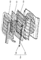
- FIG. 9 is an exploded perspective view showing a cassette including the filter 101 and the filter drive shaft 104 of the conventional air conditioner described in Patent Document 1.
- the filter 101 of the cassette of the filter cleaning unit described in Patent Document 1 is sandwiched and held by the filter holding frame 102 and the filter holding frame 103 from the vertical direction.
- Each of the filter holding frames 102 and 103 has a rectangular shape, and one side of the four sides is open.
- the cassette has a quadrangular shape when viewed from the air suction direction.
- the filter drive shaft 104 is provided on one side of the cassette.
- the filter drive shaft 104 has a resin gear-shaped gear portion 106 on both sides of the filter drive shaft 104, and a metal shaft portion 105 connecting the gear portions 106 on both sides.
- the filter 101 has a rack provided on the back surface of the filter 101.
- the cassette is arranged so that the rack of the filter 101 and the teeth of the gear portion 106 of the filter drive shaft 104 mesh with each other.
- the gear unit 106 rotates. Due to the rotation of the gear portion 106, the gear portions 106 on both sides of the filter drive shaft 104 are interlocked and rotated via the shaft portion 105. At this time, since the teeth of the gear portion 106 and the rack on the back surface of the filter 101 are arranged so as to mesh with each other, the filter 101 moves as the filter drive shaft 104 rotates. Specifically, the filter 101 slides in the direction of the open side of the filter holding frames 102 and 103. At this time, the cassette is provided with a brush or the like arranged so as to come into contact with the slidingly moving filter 101. Therefore, as the slide moves, the brush and the filter 101 come into contact with each other, and dust and the like attached to the filter 101 are removed.
- the filter cleaning unit of the conventional air conditioner includes the metal shaft portion 105 and the filter drive shaft 104 having the resin gear portion 106.
- the gear portions 106 at both ends of the shaft portion 105 are connected to each other through the shaft portion 105, and the gear portion 106 on the other end side also rotates as the gear portion 106 on the one end side rotates. ..
- the filter holding frames 102 and 103 and the gear portion 106 of the cassette can be molded with a resin material, but the shaft portion 105 needs to be molded with a metal material. That is, it is necessary to prepare in advance two types of parts, which are metal parts and resin parts. Generally, metal parts are more expensive than resin parts. Further, it is necessary to connect the gear portions 106 to both ends of the shaft portion 105. Further, when the gear portion 106 is mounted, it is necessary to connect the gear portion 106 provided on both ends of the shaft portion 105 to the shaft portion 105 so that the positions of the teeth of the gear portion 106 are aligned with each other. Therefore, when connecting the gear portion 106 and the shaft portion 105, the number of manufacturing steps is further increased.
- the filter drive shaft 104 and the filter cleaning unit of the conventional air conditioner are required to be further improved in terms of cost and manufacturing.
- the present invention provides a low-cost filter drive shaft and a filter cleaning unit using the drive shaft.
- the drive shaft of the present invention includes a first shaft portion having a substantially semicircular cross section, a first drive shaft member including a first gear provided at one end of the first shaft portion, and a substantially semicircular shape. And a second drive shaft member including a second gear provided at one end of the second shaft portion.
- the first shaft portion and the second shaft portion have a curved surface portion including an arc having a substantially semicircular cross section and a flat surface portion including a chord having a substantially semicircular cross section.
- the drive shaft has a shaft portion that is formed in a substantially cylindrical shape by overlapping the flat surface portion of the first drive shaft member and the flat surface portion of the second drive shaft member with each other.
- the drive shaft can be integrally formed with a resin material without using a metal part. This makes it possible to produce the drive shaft at low cost and reduce the occurrence of twisting between the first gear and the second gear.
- the filter cleaning unit of the present invention includes the above-mentioned drive shaft, a filter having a protrusion that meshes with the first gear and the second gear on one surface, and a filter holding portion that slidably holds the filter.
- the filter cleaning unit can be provided at low cost by using the low-cost drive shaft.
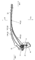
- FIG. 1 is a view showing a cross section of an indoor unit of an air conditioner incorporating a drive shaft and a filter cleaning unit using the drive shaft according to an embodiment of the present invention.
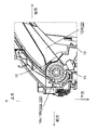
- FIG. 2 is a figure which shows the cross section of the filter cleaning unit of the indoor unit of the same air conditioner.
- FIG. 3 is a perspective view showing a filter cleaning unit in which the filter of the indoor unit of the air conditioner is omitted.
- FIG. 4 is a diagram showing a partially enlarged cross section around the drive shaft of the filter cleaning unit according to the embodiment.
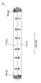
- FIG. 5 is a front view of the drive shaft according to the embodiment.
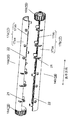
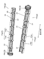
- FIG. 6 is an exploded perspective view of the drive shaft according to the embodiment.
- FIG. 7 is an exploded perspective view showing the inside of the drive shaft according to the embodiment.
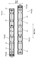
- FIG. 8 is an exploded plan view of the drive shaft according to the embodiment.
- FIG. 9 is an exploded perspective view showing a cassette including a filter and a filter drive shaft of a conventional air conditioner.
- the upper surface opening 2b side which will be described later, will be referred to as the upper side, the opposite side as the lower side, the front panel 3 side as the front side, and the opposite side as the rear side.
- the left side depth side
- the right side front side
- FIG. 1 is a view showing a cross section of an indoor unit 1 of an air conditioner in which a drive shaft 14 according to the present embodiment and a filter cleaning unit 11 using the drive shaft 14 are incorporated.
- the indoor unit 1 of the air conditioner includes a main body 2, a front opening 2a opening to the front side of the main body 2, an upper opening 2b opening to the upper side of the main body 2, and the like.
- the front opening 2a is covered with a front panel 3 which can be opened and closed.
- the front panel 3 is normally held in a closed state and opened when the user performs maintenance work, for example.
- the main body 2 includes a fan 5, a heat exchanger 4, a filter 10, a filter cleaning unit 11 and the like arranged inside the main body 2.
- the fan 5 sucks the air in the room from the top opening 2b by the rotation during driving. Then, the fan 5 blows the sucked air through the ventilation passage 9 into the room from the air outlet 6 provided below the main body 2.
- the heat exchanger 4 is formed in a substantially U-shape (including the U-shape) in a cross section in the front-rear direction, and is arranged so as to surround the periphery of the fan 5. Therefore, the heat exchanger is not provided in the part of the ventilation passage 9 on the blower outlet 6 side. Then, the air sucked from the upper surface opening 2b is heat-exchanged with the refrigerant flowing in the heat exchanger 4. The heat-exchanged air is blown out from the air outlet 6 by the rotation of the fan 5. As a result, air conditioning in a room or the like is performed via the air conditioner.
- the air outlet 6 is provided in the air conditioner so as to blow the air into the room.
- the air outlet 6 has a vertical airflow direction changing blade 7, a horizontal airflow direction changing blade 8, and the like, which are arranged in the periphery.
- the up-down air direction changing vane 7 opens and closes the air outlet 6 and changes the air blowing direction up and down.
- the left and right wind direction changing vanes 8 change the air blowing direction to the left and right.
- the vertical airflow direction changing vanes 7 are controlled to open, and the air outlet 6 is opened.
- the air in the room is taken into the indoor unit 1 through the upper surface opening 2b.
- the air taken in is heat-exchanged by the heat exchanger 4.
- the heat-exchanged air passes through the ventilation passage 9 formed on the downstream downstream side of the fan 5 in the blowing direction, and is blown out into the room from the air outlet 6.
- air conditioning in a room or the like is executed.
- the filter 10 is provided between the upper surface opening 2 b of the main body 2 and the heat exchanger 4.
- the filter 10 attaches and removes dust and the like contained in the air in the room taken in through the front opening 2a and the upper opening 2b.
- the filter 10 includes a frame portion and a net portion held by the frame portion.
- the air conditioner of the present embodiment includes the filter cleaning unit 11 including the drive shaft 14 described above.
- the filter cleaning unit 11 has a function of automatically cleaning dust attached to the mesh portion of the filter 10.
- FIG. 2 is a view showing a cross section of the filter cleaning unit 11 of the indoor unit 1 of the air conditioner.
- FIG. 3 is a perspective view showing the filter cleaning unit 11 without the filter.
- FIG. 4 is a diagram showing a partially enlarged cross section around the drive shaft 14 of the filter cleaning unit 11.
- the filter cleaning unit 11 includes a filter 10, a filter holding portion 12, a drive shaft 14, a brush 15, a dust receiving member 16, an exhaust device (not shown) exemplified by a fan, and the like. Composed of.
- the filter holding portion 12 is configured to sandwich the filter 10 vertically and holds the filter 10 slidably.
- the drive shaft 14 slides and conveys the filter 10.
- the brush 15 scrapes and removes dust and the like adhering to the filter 10.
- the dust receiving member 16 receives and collects dust and the like removed by the brush 15.
- the exhaust device discharges dust and the like accumulated in the dust receiving member 16 to a predetermined place.
- the filter holding part 12 includes a normal guide part 12A for holding the filter 10 and a folded back guide part 12B. Then, by the rotation operation of the drive shaft 14 described later, the filter 10 is slid and conveyed from the normal guide portion 12A to the folding guide portion 12B, or from the reverse folding guide portion 12B to the normal guide portion 12A.
- the drive shaft 14 is provided at both ends of the shaft portion 17 (see FIG. 5) extending in the width direction (the depth direction in FIG. 1) of the indoor unit 1, and the gear portion 18
- the first gear 18a, the second gear 18b, and the like constituting the above are provided.
- the first gear 18a and the second gear 18b are formed in a cylindrical shape and have teeth formed by integral molding over the entire circumference.
- the shaft 17, the first gear 18a, and the second gear 18b are formed to have substantially the same diameter (including the same diameter). Further, the teeth formed on the first gear 18a and the second gear 18b are provided with the same number and the same pitch.
- the filter 10 includes rack teeth 19 which are formed on the back surface side and form protrusions.
- the rack teeth 19 of the filter 10 are formed so as to engage with the teeth formed over the entire circumference of the first gear 18a and the second gear 18b when the filter 10 is wound around the shaft portion 17.
- the brush 15 is provided below the drive shaft 14 along the drive shaft 14 in the width direction of the indoor unit 1 (depth direction in FIG. 4 ).
- the brush 15 is configured to be vertically reversible. For example, when cleaning the filter 10, the brush 15 is arranged facing upward so as to contact the filter 10. As a result, the dust adhering to the surface of the filter 10 is scraped off by the brush 15 and removed.
- the dust receiving member 16 is arranged along the brush 15 in the width direction of the indoor unit 1 (the depth direction in FIG. 2) so as to cover the lower side of the brush 15.
- the dust receiving member 16 is connected to an exhaust device (not shown), and is configured to discharge dust and the like accumulated inside to a predetermined place.
- the dust receiving member 16 includes a blade 20 provided inside and below the brush 15 and made of an elastic body such as rubber.
- the blade 20 removes dust and the like adhering to the brush 15 from the filter 10 in a state where the brush 15 is inverted downward. As a result, the removed dust or the like is accumulated in the dust receiving member 16 and discharged.
- the filter cleaning unit 11 is configured as described above.
- the filter 10 is arranged in the normal guide portion 12A of the filter holding portion 12 as shown in FIG. 1 during normal use of the air conditioner.
- the filter 10 removes dust and the like contained in the indoor air taken in through the upper surface opening 2b.
- the brush 15 is attached to the surface of the filter 10 (the surface opposite to the surface on which the rack teeth 19 are formed; the surface to which dust is attached). It is arranged upward so as to abut.
- the drive shaft 14 is rotationally driven by a drive source such as a motor.
- the first gear 18a and the second gear 18b rotate in the forward direction (counterclockwise in FIG. 2), and the filter 10 is slid and conveyed from the normal guide portion 12A to the folding guide portion 12B.
- one end of the filter 10 passes through the confluent portion 12C of the folded guide portion 12B and the normal guide portion 12A and reaches the final end of the normal guide portion 12A.
- the first gear 18a and the second gear 18b rotate in opposite directions (clockwise in FIG. 2).
- the filter 10 is slid and conveyed from the folding guide portion 12B to the normal guide portion 12A.
- the cleaning operation of the filter 10 of the filter cleaning unit 11 is executed.
- FIG. 5 is a front view of the drive shaft 14 according to the same embodiment.
- FIG. 6 is an exploded perspective view of the drive shaft 14.
- FIG. 7 is an exploded perspective view showing the inside of the drive shaft 14.
- FIG. 8 is an exploded plan view of the drive shaft 14.
- the drive shaft 14 includes the shaft portion 17, the gear portion 18, and the like, as described above.
- the shaft portion 17 includes a first shaft portion 17a, a second shaft portion 17b, and the like.
- the first shaft portion 17a and the second shaft portion 17b have flat surface portions 17ab and 17bb and curved surface portions 17aa and 17ba, which will be described later.
- the gear unit 18 includes a first gear 18a, a second gear 18b, and the like, and is arranged at both ends of the shaft unit 17.
- the shaft portion 17 is configured by arranging the flat surface portion 17ab of the first shaft portion 17a and the flat surface portion 17bb of the second shaft portion 17b so as to overlap each other.
- the first shaft portion 17a and the first gear 18a are integrally molded with a resin material such as ABS resin to form the first drive shaft member 14a.
- the second shaft portion 17b and the second gear 18b are integrally molded with a resin material such as ABS to form the second drive shaft member 14b.
- the drive shaft 14 includes a first drive shaft member 14a and a second drive shaft member 14b, which are a pair of half-split integral parts that are split in half along the longitudinal direction. Are formed by joining
- first drive shaft member 14a and the second drive shaft member 14b have a first shaft portion 17a and a second shaft portion 17b obtained by dividing the shaft portion 17 in half. That is, the first drive shaft member 14a is formed to include the first shaft portion 17a, and the second drive shaft member 14b is formed to include the second shaft portion 17b.
- the first drive shaft member 14a is composed of a first shaft portion 17a and a first gear wheel 18a in a completed gear state integrally molded with one end of the first shaft portion 17a (left side in FIG. 6).
- the first shaft portion 17a has a semicircular cross section that is parallel to the rotation direction. Therefore, the first shaft portion 17a includes a curved surface portion 17aa including the arc in the cross section and a flat surface portion 17ab including the chord.
- the first shaft portion 17a has a plurality of convex portions 21 provided on the left side (the first gear 18a side) and a plurality of concave portions 22 provided on the right side with the center in the longitudinal direction of the first shaft portion 17a as a boundary.
- the plurality of convex portions 21 are provided so as to protrude from the flat surface portion 17ab of the first shaft portion 17a.
- the plurality of concave portions 22 are provided so as to bite into the curved surface portion 17aa from the flat surface portion 17ab.
- the second drive shaft member 14b is in a completed gear state integrally molded with the second shaft portion 17b and the other end of the second shaft portion 17b (the opposite side of the first drive shaft member 14a; the right side in FIG. 6). It is composed of the second gear 18b.
- the second shaft portion 17b has a semicircular cross section that is parallel to the rotation direction. Therefore, the second shaft portion 17b includes a curved surface portion 17ba including an arc in the cross section and a flat surface portion 17bb including a chord.
- the second shaft portion 17b like the first shaft portion 17a, has a plurality of convex portions 21 provided on the right side (second gear 18b side) with the longitudinal center of the second shaft portion 17b as a boundary.
- the plurality of convex portions 21 are provided so as to protrude from the flat surface portion 17bb.
- the plurality of recesses 22 are provided so as to bite into the curved surface portion 17ba from the flat surface portion 17bb.
- the drive shaft 14 may be formed by fitting the concave portion 22 of the first shaft portion 17a into the corresponding convex portion 21 of the second shaft portion 17b.
- the convex portion 21 of the first shaft portion 17a is in the concave portion 22 of the second shaft portion 17b
- the convex portion 21 of the second shaft portion 17b is in the concave portion 22 of the first shaft portion 17a.
- the drive shafts 14 formed by fitting each are shown.
- the drive shaft 14 including the shaft portion 17 including the first shaft portion 17a and the second shaft portion 17b including the first gear 18a and the second gear 18b at both ends is configured.
- the first drive shaft member 14a of the present embodiment is provided with a plurality of recesses 22 on the side having the first gear 18a with the substantially center (including the center) of the first shaft portion 17a in the longitudinal direction as a boundary, A plurality of convex portions 21 are provided on the side not having the first gear 18a.
- the second drive shaft member 14b is provided with a plurality of recesses 22 on the side having the second gear 18b with the substantially center (including the center) in the longitudinal direction of the second shaft portion 17b as a boundary.
- a plurality of convex portions 21 are provided on the side not having.
- first drive shaft member 14a and the second drive shaft member 14b are configured by members having the same shape. Then, the convex portion 21 of the first drive shaft member 14a on one side is fitted and joined to the concave portion 22 of the second drive shaft member 14b on the other side. As a result, the drive shaft 14 including the first gear 18a and the second gear 18b is formed at both ends of the shaft portion 17.
- the shaft portion 17 of the drive shaft 14 is formed in a hollow shape in a state where the first shaft portion 17a and the second shaft portion 17b are fitted together. That is, the first shaft portion 17a is formed in a shape that opens from the flat surface portion 17ab to the curved surface portion 17aa. Similarly, the second shaft portion 17b is formed in a shape that opens from the flat surface portion 17bb to the curved surface portion 17ba. As a result, the inside of the shaft portion 17 is formed in a hollow shape.
- first drive shaft member 14a is provided inside the curved surface portion 17aa, and is formed along the inner surface axial direction (longitudinal direction) of the first shaft portion 17a, and the first reinforcing rib 23. It has a plurality of second reinforcing ribs 24 formed in a direction intersecting with (shorter direction).
- the second drive shaft member 14b intersects with the first reinforcing rib 23, which is provided inside the curved surface portion 17ba and is formed along the inner surface axial direction of the second shaft portion 17b. It has a plurality of second reinforcing ribs 24 formed in the direction.
- the drive shaft 14 is configured as described above.
- the drive shaft 14 is similar to the first drive shaft member 14a in which the first shaft portion 17a and the first gear 18a are integrally molded of a resin material and the second drive shaft member 14a. It is composed of a drive shaft member 14b. Therefore, the material cost can be reduced as compared with the conventional filter drive shaft formed by combining the metal component and the resin component. Thereby, the drive shaft 14 can be formed at low cost.
- the drive shaft 14 has a convex portion 21 and a concave portion 22 provided on flat surface portions 17ab and 17bb which are half-divided surfaces of the first drive shaft member 14a and the second drive shaft member 14b in which the shaft portion 17 is formed in a half-divided shape. Can be integrated simply by fitting. Therefore, the assemblability of the drive shaft 14 is improved and the inexpensive drive shaft 14 can be provided.
- the filter cleaning unit 11 of the present embodiment can be configured using the drive shaft 14 that is low in cost and excellent in assembling. Therefore, the filter cleaning unit 11 can be realized at low cost.
- the shaft portion 17 is formed in a hollow shape by joining the hollow first shaft portion 17a and the second shaft portion 17b. Therefore, since the cost of the resin material forming the shaft portion 17 is reduced, the shaft portion 17 can be provided at a lower cost. At the same time, the weight of the drive shaft 14 can be reduced. This further improves the handleability as a component when the shaft portion 17 is assembled.
- first drive shaft member 14a and second drive shaft member 14b forming the drive shaft 14 are the constituent members, that is, the first gear 18a, the second gear 18b, the concave portion 22 and the convex portion 21 are bilaterally symmetrical. It is arranged so that.
- the first drive shaft member 14a and the second drive shaft member 14b can be configured by parts having the same shape, which facilitates parts management.
- the mold for integrally molding the first drive shaft member 14a and the second drive shaft member 14b can be configured by one type. Therefore, it is possible to significantly reduce the production cost and realize the drive shaft 14 at a lower cost.
- the shaft portion 17 of the drive shaft 14 is formed in a hollow shape. Therefore, as compared with a solid shaft portion having a long columnar shape along the rotation axis direction, it is possible to reduce the occurrence of axial line deflection due to sink marks due to the thickness of the shaft portion. Accordingly, even if the drive shaft 14 of the filter is configured by the resin shaft portion 17, the axis of the shaft portion 17 can be stably maintained in a straight line.
- first shaft portion 17a and the second shaft portion 17b that form the hollow shaft portion 17 include a first reinforcing rib 23 formed along the inner surface axial direction (longitudinal direction), and a first reinforcing rib 23. It has a plurality of second reinforcing ribs 24 formed in the intersecting direction (shorter direction).
- the torque is transmitted to the first drive shaft member 14a and the second drive shaft member 14b via the flat surface portion 17ab of the first shaft portion 17a and the flat surface portion 17bb of the second shaft portion 17b during rotational driving. .. Therefore, even when a driving motor is provided and driven only on the first gear 18a side, the driving force of the motor is generated through the flat surface portion 17ab of the first shaft portion 17a and the flat surface portion 17bb of the second shaft portion 17b. It is reliably transmitted, and the torque is transmitted to the second gear 18b. As a result, even when the drive shaft 14 is used to drive the filter 10, it is possible to more reliably reduce the bending and displacement between the first gear 18a and the second gear 18b.
- the filter cleaning unit 11 of the present embodiment includes the drive shaft 14 having the above configuration. Therefore, the flatness of the filter 10 that is stretched around the shaft portion 17 can be increased by the shaft portion 17 that is highly flat and has no bending. Thereby, the brush 15 can be contacted more reliably over the entire width of the filter 10. As a result, the cleaning performance of the filter 10 with the brush 15 can be further improved.
- the first shaft portion 17a and the second shaft portion 17b forming the shaft portion 17 are formed in a half-split shape.
- the first gear 18a and the second gear 18b that form the gear unit 18 are formed by a complete gear having a cylindrical shape instead of a half-split shape. Therefore, even if an excessive torque is applied to the gear portion 18 for some reason during the slide conveyance of the filter 10, the gear portion 18 is unlikely to be separated or damaged. Thereby, the drive shaft 14 that can maintain high reliability for a long period of time can be realized.
- the first gear 18a and the second gear 18b are each formed as an integrated product. As a result, it is possible to prevent separation damage or the like that is likely to occur in the gear part that is a combination of the halved shapes. As a result, the drive shaft 14 with higher reliability can be realized.
- the filter cleaning unit 11 of the present embodiment includes the drive shaft 14 having the above configuration. Therefore, there is no need to worry about the occurrence of separation damage or the like of the gear portion 18 of the drive shaft 14. Thereby, the filter cleaning unit 11 with high reliability can be realized.
- an air conditioner has been described as an example of the device using the drive shaft 14 of the filter 10 and the filter cleaning unit 11, but the device is not limited to this.
- the device may be, for example, an air purifier. That is, as long as it is a device that uses a filter that can be transported, it is not particularly limited, and any device may be used.
- the drive shaft of the present invention includes a first shaft portion having a substantially semicircular cross section, and a first drive shaft member including a first gear provided at one end of the first shaft portion.
- a second drive shaft member including a second shaft portion having a substantially semicircular cross section and a second gear provided at one end of the second shaft portion.
- the first shaft portion and the second shaft portion have a curved surface portion including an arc having a substantially semicircular cross section and a flat portion including a chord having a substantially semicircular cross section.
- the drive shaft has a shaft portion that is formed in a substantially cylindrical shape by overlapping the flat surface portion of the first drive shaft member and the flat surface portion of the second drive shaft member with each other.
- the shaft portion and the gear can be integrally formed of resin material. Therefore, the material cost can be reduced as compared with the drive shaft formed by combining the metal parts and the resin parts. Further, the drive shaft is integrally formed by stacking the flat surface portions of the shaft portion. Therefore, it is possible to provide an inexpensive drive shaft that is excellent in assemblability.
- the drive shaft of the present invention preferably has a hollow shaft portion.
- the material cost of the shaft portion of the drive shaft can be reduced, and the weight of the drive shaft of the filter can be reduced. Therefore, an inexpensive and highly convenient drive shaft can be provided. Further, in the case of a shape in which the length of the rotary shaft along the shaft portion is long, it is possible to reduce the occurrence of axial line deflection due to sink marks which is likely to occur in the configuration of the solid shaft portion. As a result, it is possible to provide a drive shaft that achieves good filter drive performance even if the shaft portion is made of resin.
- the first gear of the drive shaft of the present invention has teeth provided on the entire circumference of the first drive shaft member.
- the first gear is a complete gear of the first drive shaft member. Therefore, even when a large torque is applied to the first gear, separation and damage of the first gear can be reduced.
- the meshing of the first gear and the filter becomes good. Therefore, it is possible to reduce the occurrence of phenomena such as the filter slipping with respect to the position of the first gear.
- the second gear of the drive shaft of the present invention preferably has a configuration in which teeth are provided on the entire circumference of the second drive shaft member.
- the second gear is also composed of a completed gear of the same body as the first gear. This makes it possible to provide a more reliable drive shaft.
- each of the flat surface portion of the first shaft portion and the flat surface portion of the second shaft portion includes a convex portion and a concave portion, and the corresponding convex portion and second axial portion of the first shaft portion are provided. It is desirable to have a configuration in which the concave portion is fitted.
- the two members when the drive shaft is manufactured, the two members can be easily combined and manufactured based on the corresponding protrusions and recesses. Thereby, the drive shaft can be easily manufactured with high productivity. As a result, the drive shaft can be realized at a lower cost.
- the filter cleaning unit of the present invention includes the above-mentioned drive shaft, a filter having a protrusion that meshes with the first gear and the second gear on one surface, and a filter holding portion that slidably holds the filter.
- an inexpensive drive shaft can be used for the filter cleaning unit. This can reduce the cost of the filter cleaning unit. Furthermore, by providing an inexpensive filter cleaning unit, a low-cost device such as an air conditioner can be realized.
- the drive shaft of the filter can be provided at low cost, and the filter cleaning unit using the drive shaft can also be provided at low cost. Therefore, the drive shaft and the filter cleaning unit can be widely applied to domestic and commercial air conditioners.
Landscapes
- Engineering & Computer Science (AREA)
- Chemical & Material Sciences (AREA)
- Combustion & Propulsion (AREA)
- Mechanical Engineering (AREA)
- General Engineering & Computer Science (AREA)
- Air Filters, Heat-Exchange Apparatuses, And Housings Of Air-Conditioning Units (AREA)
Abstract
La présente invention concerne un arbre d'entraînement (14) comprenant : une première partie arbre (17a) ayant une forme semi-circulaire; un premier élément d'arbre d'entraînement (14a) comprenant un premier engrenage (18a) disposé à une extrémité du premier arbre (17a); une seconde partie arbre (17b) ayant une forme semi-circulaire; et un second élément d'arbre d'entraînement (14b) comprenant un second engrenage (18b) disposé à une extrémité de la partie arbre. La première partie arbre (17a) et la seconde partie arbre (17b) ont des sections de surface incurvées (17aa, 17ba) comprenant des arcs semi-circulaires et des sections de surface plates (17ab, 17bb) ayant des cordes, respectivement. Les parties de surface plate (17ab, 17bb) du premier élément d'arbre d'entraînement (14a) et du second élément d'arbre d'entraînement (14b) se chevauchent mutuellement pour former une partie arbre cylindrique (17). Par conséquent, l'arbre d'entraînement (14) peut être moulé d'un seul tenant à l'aide d'un matériau de résine, et peut ainsi être fabriqué à faible coût. En outre, la torsion entre le premier engrenage (18a) et le second engrenage (18b) peut être réduite.
Applications Claiming Priority (2)
| Application Number | Priority Date | Filing Date | Title |
|---|---|---|---|
| JP2019028977A JP7300577B2 (ja) | 2019-02-21 | 2019-02-21 | 駆動軸及びそれを用いたフィルタ掃除ユニット |
| JP2019-028977 | 2019-12-26 |
Publications (1)
| Publication Number | Publication Date |
|---|---|
| WO2020171027A1 true WO2020171027A1 (fr) | 2020-08-27 |
Family
ID=72143682
Family Applications (1)
| Application Number | Title | Priority Date | Filing Date |
|---|---|---|---|
| PCT/JP2020/006136 Ceased WO2020171027A1 (fr) | 2019-02-21 | 2020-02-17 | Arbre d'entraînement et unité de nettoyage de filtre utilisant celui-ci |
Country Status (2)
| Country | Link |
|---|---|
| JP (1) | JP7300577B2 (fr) |
| WO (1) | WO2020171027A1 (fr) |
Citations (8)
| Publication number | Priority date | Publication date | Assignee | Title |
|---|---|---|---|---|
| JPS59121217A (ja) * | 1982-12-27 | 1984-07-13 | Canon Inc | 回転体の駆動軸 |
| JPS6363283B2 (fr) * | 1980-01-30 | 1988-12-07 | ||
| JP2008138927A (ja) * | 2006-12-01 | 2008-06-19 | Matsushita Electric Ind Co Ltd | 天井埋込形空気調和機 |
| US20100278586A1 (en) * | 2007-06-28 | 2010-11-04 | European Aeronautic Defence And Space Company Eads France | Structural connecting rod made of a composite and process for producing such a connecting rod |
| JP2016527100A (ja) * | 2013-06-05 | 2016-09-08 | ハチンソン | 複合連接棒、そのような棒を製造するための方法、及びそれを組み込んだ航空機用の天井構造又は床構造 |
| CN205939630U (zh) * | 2016-07-15 | 2017-02-08 | 广东美的制冷设备有限公司 | 滤网驱动件和空调室内机 |
| JP2018066563A (ja) * | 2018-02-06 | 2018-04-26 | 三菱電機株式会社 | 空気調和機の室内機 |
| WO2019030861A1 (fr) * | 2017-08-09 | 2019-02-14 | 三菱電機株式会社 | Unité intérieure de climatiseur et climatiseur équipé de celle-ci |
Family Cites Families (1)
| Publication number | Priority date | Publication date | Assignee | Title |
|---|---|---|---|---|
| JP6363283B1 (ja) | 2017-09-26 | 2018-07-25 | 宇部樹脂加工株式会社 | 保護カバー |
-
2019
- 2019-02-21 JP JP2019028977A patent/JP7300577B2/ja active Active
-
2020
- 2020-02-17 WO PCT/JP2020/006136 patent/WO2020171027A1/fr not_active Ceased
Patent Citations (8)
| Publication number | Priority date | Publication date | Assignee | Title |
|---|---|---|---|---|
| JPS6363283B2 (fr) * | 1980-01-30 | 1988-12-07 | ||
| JPS59121217A (ja) * | 1982-12-27 | 1984-07-13 | Canon Inc | 回転体の駆動軸 |
| JP2008138927A (ja) * | 2006-12-01 | 2008-06-19 | Matsushita Electric Ind Co Ltd | 天井埋込形空気調和機 |
| US20100278586A1 (en) * | 2007-06-28 | 2010-11-04 | European Aeronautic Defence And Space Company Eads France | Structural connecting rod made of a composite and process for producing such a connecting rod |
| JP2016527100A (ja) * | 2013-06-05 | 2016-09-08 | ハチンソン | 複合連接棒、そのような棒を製造するための方法、及びそれを組み込んだ航空機用の天井構造又は床構造 |
| CN205939630U (zh) * | 2016-07-15 | 2017-02-08 | 广东美的制冷设备有限公司 | 滤网驱动件和空调室内机 |
| WO2019030861A1 (fr) * | 2017-08-09 | 2019-02-14 | 三菱電機株式会社 | Unité intérieure de climatiseur et climatiseur équipé de celle-ci |
| JP2018066563A (ja) * | 2018-02-06 | 2018-04-26 | 三菱電機株式会社 | 空気調和機の室内機 |
Also Published As
| Publication number | Publication date |
|---|---|
| JP2020134037A (ja) | 2020-08-31 |
| JP7300577B2 (ja) | 2023-06-30 |
Similar Documents
| Publication | Publication Date | Title |
|---|---|---|
| US20090047133A1 (en) | Impeller blade for centrifugal blower, blade-supporting rotator, impeller for centrifugal blower, and method for manufacturing impeller for centrifugal blower | |
| CN103790859B (zh) | 螺旋桨式风机和具有该螺旋桨式风机的空调 | |
| CN103017308B (zh) | 一种分体落地式空调器 | |
| JP4761323B2 (ja) | 遠心ファン、成型用金型および流体送り装置 | |
| US9447790B2 (en) | Cross-flow fan | |
| JP5018594B2 (ja) | 換気装置 | |
| JP5212438B2 (ja) | フィルタ移動機構及び空調室内機 | |
| JP4878599B2 (ja) | 空気調和機の室内機 | |
| JP2007100975A (ja) | 空気調節装置 | |
| CN103075791A (zh) | 空气调节器的室内机 | |
| JP6767635B2 (ja) | 空気調和機 | |
| CN110325800A (zh) | 空气调节机 | |
| JP7300577B2 (ja) | 駆動軸及びそれを用いたフィルタ掃除ユニット | |
| JP6998506B2 (ja) | 空気調和機 | |
| CN102865625B (zh) | 空调室内机 | |
| WO2018163548A1 (fr) | Climatiseur | |
| CN105823190A (zh) | 一种风口结构及其制造方法 | |
| JP5585318B2 (ja) | 空調室内機 | |
| JP6835259B2 (ja) | 吹出パネルおよび空調室内機 | |
| JP6754945B2 (ja) | 空気調和機 | |
| JP6998505B2 (ja) | 空気調和機 | |
| JP5345607B2 (ja) | 遠心ファン、成型用金型および流体送り装置 | |
| JP5469635B2 (ja) | 遠心ファン、成型用金型および流体送り装置 | |
| JP2019007653A (ja) | 空気調和機 | |
| CN211400037U (zh) | 散风组件及空调器 |
Legal Events
| Date | Code | Title | Description |
|---|---|---|---|
| 121 | Ep: the epo has been informed by wipo that ep was designated in this application |
Ref document number: 20760155 Country of ref document: EP Kind code of ref document: A1 |
|
| NENP | Non-entry into the national phase |
Ref country code: DE |
|
| 122 | Ep: pct application non-entry in european phase |
Ref document number: 20760155 Country of ref document: EP Kind code of ref document: A1 |