WO2020171027A1 - 駆動軸およびそれを用いたフィルタ掃除ユニット - Google Patents
駆動軸およびそれを用いたフィルタ掃除ユニット Download PDFInfo
- Publication number
- WO2020171027A1 WO2020171027A1 PCT/JP2020/006136 JP2020006136W WO2020171027A1 WO 2020171027 A1 WO2020171027 A1 WO 2020171027A1 JP 2020006136 W JP2020006136 W JP 2020006136W WO 2020171027 A1 WO2020171027 A1 WO 2020171027A1
- Authority
- WO
- WIPO (PCT)
- Prior art keywords
- drive shaft
- filter
- gear
- shaft
- shaft portion
- Prior art date
- Legal status (The legal status is an assumption and is not a legal conclusion. Google has not performed a legal analysis and makes no representation as to the accuracy of the status listed.)
- Ceased
Links
Images


Classifications
-
- F—MECHANICAL ENGINEERING; LIGHTING; HEATING; WEAPONS; BLASTING
- F24—HEATING; RANGES; VENTILATING
- F24F—AIR-CONDITIONING; AIR-HUMIDIFICATION; VENTILATION; USE OF AIR CURRENTS FOR SCREENING
- F24F1/00—Room units for air-conditioning, e.g. separate or self-contained units or units receiving primary air from a central station
- F24F1/0007—Indoor units, e.g. fan coil units
- F24F1/0071—Indoor units, e.g. fan coil units with means for purifying supplied air
-
- F—MECHANICAL ENGINEERING; LIGHTING; HEATING; WEAPONS; BLASTING
- F24—HEATING; RANGES; VENTILATING
- F24F—AIR-CONDITIONING; AIR-HUMIDIFICATION; VENTILATION; USE OF AIR CURRENTS FOR SCREENING
- F24F1/00—Room units for air-conditioning, e.g. separate or self-contained units or units receiving primary air from a central station
- F24F1/0007—Indoor units, e.g. fan coil units
- F24F1/0071—Indoor units, e.g. fan coil units with means for purifying supplied air
- F24F1/0073—Indoor units, e.g. fan coil units with means for purifying supplied air characterised by the mounting or arrangement of filters
-
- F—MECHANICAL ENGINEERING; LIGHTING; HEATING; WEAPONS; BLASTING
- F24—HEATING; RANGES; VENTILATING
- F24F—AIR-CONDITIONING; AIR-HUMIDIFICATION; VENTILATION; USE OF AIR CURRENTS FOR SCREENING
- F24F1/00—Room units for air-conditioning, e.g. separate or self-contained units or units receiving primary air from a central station
- F24F1/02—Self-contained room units for air-conditioning, i.e. with all apparatus for treatment installed in a common casing
- F24F1/0328—Self-contained room units for air-conditioning, i.e. with all apparatus for treatment installed in a common casing with means for purifying supplied air
-
- F—MECHANICAL ENGINEERING; LIGHTING; HEATING; WEAPONS; BLASTING
- F24—HEATING; RANGES; VENTILATING
- F24F—AIR-CONDITIONING; AIR-HUMIDIFICATION; VENTILATION; USE OF AIR CURRENTS FOR SCREENING
- F24F13/00—Details common to, or for air-conditioning, air-humidification, ventilation or use of air currents for screening
- F24F13/28—Arrangement or mounting of filters
Definitions
- the present invention relates to a drive shaft of a filter used in an air conditioner and the like, and a filter cleaning unit using the drive shaft.
- Patent Document 1 discloses a filter drive shaft that is rotated by a drive source such as a motor, and a filter cleaning unit using the filter drive shaft.
- the filter cleaning unit disclosed in Patent Document 1 slides a filter by rotating a filter drive shaft.
- the filter is generally provided in an air conditioner, an air cleaner, or the like to remove dust and the like from the sucked air.
- FIG. 9 is an exploded perspective view showing a cassette including the filter 101 and the filter drive shaft 104 of the conventional air conditioner described in Patent Document 1.
- the filter 101 of the cassette of the filter cleaning unit described in Patent Document 1 is sandwiched and held by the filter holding frame 102 and the filter holding frame 103 from the vertical direction.
- Each of the filter holding frames 102 and 103 has a rectangular shape, and one side of the four sides is open.
- the cassette has a quadrangular shape when viewed from the air suction direction.
- the filter drive shaft 104 is provided on one side of the cassette.
- the filter drive shaft 104 has a resin gear-shaped gear portion 106 on both sides of the filter drive shaft 104, and a metal shaft portion 105 connecting the gear portions 106 on both sides.
- the filter 101 has a rack provided on the back surface of the filter 101.
- the cassette is arranged so that the rack of the filter 101 and the teeth of the gear portion 106 of the filter drive shaft 104 mesh with each other.
- the gear unit 106 rotates. Due to the rotation of the gear portion 106, the gear portions 106 on both sides of the filter drive shaft 104 are interlocked and rotated via the shaft portion 105. At this time, since the teeth of the gear portion 106 and the rack on the back surface of the filter 101 are arranged so as to mesh with each other, the filter 101 moves as the filter drive shaft 104 rotates. Specifically, the filter 101 slides in the direction of the open side of the filter holding frames 102 and 103. At this time, the cassette is provided with a brush or the like arranged so as to come into contact with the slidingly moving filter 101. Therefore, as the slide moves, the brush and the filter 101 come into contact with each other, and dust and the like attached to the filter 101 are removed.
- the filter cleaning unit of the conventional air conditioner includes the metal shaft portion 105 and the filter drive shaft 104 having the resin gear portion 106.
- the gear portions 106 at both ends of the shaft portion 105 are connected to each other through the shaft portion 105, and the gear portion 106 on the other end side also rotates as the gear portion 106 on the one end side rotates. ..
- the filter holding frames 102 and 103 and the gear portion 106 of the cassette can be molded with a resin material, but the shaft portion 105 needs to be molded with a metal material. That is, it is necessary to prepare in advance two types of parts, which are metal parts and resin parts. Generally, metal parts are more expensive than resin parts. Further, it is necessary to connect the gear portions 106 to both ends of the shaft portion 105. Further, when the gear portion 106 is mounted, it is necessary to connect the gear portion 106 provided on both ends of the shaft portion 105 to the shaft portion 105 so that the positions of the teeth of the gear portion 106 are aligned with each other. Therefore, when connecting the gear portion 106 and the shaft portion 105, the number of manufacturing steps is further increased.
- the filter drive shaft 104 and the filter cleaning unit of the conventional air conditioner are required to be further improved in terms of cost and manufacturing.
- the present invention provides a low-cost filter drive shaft and a filter cleaning unit using the drive shaft.
- the drive shaft of the present invention includes a first shaft portion having a substantially semicircular cross section, a first drive shaft member including a first gear provided at one end of the first shaft portion, and a substantially semicircular shape. And a second drive shaft member including a second gear provided at one end of the second shaft portion.
- the first shaft portion and the second shaft portion have a curved surface portion including an arc having a substantially semicircular cross section and a flat surface portion including a chord having a substantially semicircular cross section.
- the drive shaft has a shaft portion that is formed in a substantially cylindrical shape by overlapping the flat surface portion of the first drive shaft member and the flat surface portion of the second drive shaft member with each other.
- the drive shaft can be integrally formed with a resin material without using a metal part. This makes it possible to produce the drive shaft at low cost and reduce the occurrence of twisting between the first gear and the second gear.
- the filter cleaning unit of the present invention includes the above-mentioned drive shaft, a filter having a protrusion that meshes with the first gear and the second gear on one surface, and a filter holding portion that slidably holds the filter.
- the filter cleaning unit can be provided at low cost by using the low-cost drive shaft.
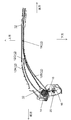
- FIG. 1 is a view showing a cross section of an indoor unit of an air conditioner incorporating a drive shaft and a filter cleaning unit using the drive shaft according to an embodiment of the present invention.
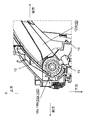
- FIG. 2 is a figure which shows the cross section of the filter cleaning unit of the indoor unit of the same air conditioner.
- FIG. 3 is a perspective view showing a filter cleaning unit in which the filter of the indoor unit of the air conditioner is omitted.
- FIG. 4 is a diagram showing a partially enlarged cross section around the drive shaft of the filter cleaning unit according to the embodiment.
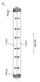
- FIG. 5 is a front view of the drive shaft according to the embodiment.
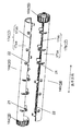
- FIG. 6 is an exploded perspective view of the drive shaft according to the embodiment.
- FIG. 7 is an exploded perspective view showing the inside of the drive shaft according to the embodiment.
- FIG. 8 is an exploded plan view of the drive shaft according to the embodiment.
- FIG. 9 is an exploded perspective view showing a cassette including a filter and a filter drive shaft of a conventional air conditioner.
- the upper surface opening 2b side which will be described later, will be referred to as the upper side, the opposite side as the lower side, the front panel 3 side as the front side, and the opposite side as the rear side.
- the left side depth side
- the right side front side
- FIG. 1 is a view showing a cross section of an indoor unit 1 of an air conditioner in which a drive shaft 14 according to the present embodiment and a filter cleaning unit 11 using the drive shaft 14 are incorporated.
- the indoor unit 1 of the air conditioner includes a main body 2, a front opening 2a opening to the front side of the main body 2, an upper opening 2b opening to the upper side of the main body 2, and the like.
- the front opening 2a is covered with a front panel 3 which can be opened and closed.
- the front panel 3 is normally held in a closed state and opened when the user performs maintenance work, for example.
- the main body 2 includes a fan 5, a heat exchanger 4, a filter 10, a filter cleaning unit 11 and the like arranged inside the main body 2.
- the fan 5 sucks the air in the room from the top opening 2b by the rotation during driving. Then, the fan 5 blows the sucked air through the ventilation passage 9 into the room from the air outlet 6 provided below the main body 2.
- the heat exchanger 4 is formed in a substantially U-shape (including the U-shape) in a cross section in the front-rear direction, and is arranged so as to surround the periphery of the fan 5. Therefore, the heat exchanger is not provided in the part of the ventilation passage 9 on the blower outlet 6 side. Then, the air sucked from the upper surface opening 2b is heat-exchanged with the refrigerant flowing in the heat exchanger 4. The heat-exchanged air is blown out from the air outlet 6 by the rotation of the fan 5. As a result, air conditioning in a room or the like is performed via the air conditioner.
- the air outlet 6 is provided in the air conditioner so as to blow the air into the room.
- the air outlet 6 has a vertical airflow direction changing blade 7, a horizontal airflow direction changing blade 8, and the like, which are arranged in the periphery.
- the up-down air direction changing vane 7 opens and closes the air outlet 6 and changes the air blowing direction up and down.
- the left and right wind direction changing vanes 8 change the air blowing direction to the left and right.
- the vertical airflow direction changing vanes 7 are controlled to open, and the air outlet 6 is opened.
- the air in the room is taken into the indoor unit 1 through the upper surface opening 2b.
- the air taken in is heat-exchanged by the heat exchanger 4.
- the heat-exchanged air passes through the ventilation passage 9 formed on the downstream downstream side of the fan 5 in the blowing direction, and is blown out into the room from the air outlet 6.
- air conditioning in a room or the like is executed.
- the filter 10 is provided between the upper surface opening 2 b of the main body 2 and the heat exchanger 4.
- the filter 10 attaches and removes dust and the like contained in the air in the room taken in through the front opening 2a and the upper opening 2b.
- the filter 10 includes a frame portion and a net portion held by the frame portion.
- the air conditioner of the present embodiment includes the filter cleaning unit 11 including the drive shaft 14 described above.
- the filter cleaning unit 11 has a function of automatically cleaning dust attached to the mesh portion of the filter 10.
- FIG. 2 is a view showing a cross section of the filter cleaning unit 11 of the indoor unit 1 of the air conditioner.
- FIG. 3 is a perspective view showing the filter cleaning unit 11 without the filter.
- FIG. 4 is a diagram showing a partially enlarged cross section around the drive shaft 14 of the filter cleaning unit 11.
- the filter cleaning unit 11 includes a filter 10, a filter holding portion 12, a drive shaft 14, a brush 15, a dust receiving member 16, an exhaust device (not shown) exemplified by a fan, and the like. Composed of.
- the filter holding portion 12 is configured to sandwich the filter 10 vertically and holds the filter 10 slidably.
- the drive shaft 14 slides and conveys the filter 10.
- the brush 15 scrapes and removes dust and the like adhering to the filter 10.
- the dust receiving member 16 receives and collects dust and the like removed by the brush 15.
- the exhaust device discharges dust and the like accumulated in the dust receiving member 16 to a predetermined place.
- the filter holding part 12 includes a normal guide part 12A for holding the filter 10 and a folded back guide part 12B. Then, by the rotation operation of the drive shaft 14 described later, the filter 10 is slid and conveyed from the normal guide portion 12A to the folding guide portion 12B, or from the reverse folding guide portion 12B to the normal guide portion 12A.
- the drive shaft 14 is provided at both ends of the shaft portion 17 (see FIG. 5) extending in the width direction (the depth direction in FIG. 1) of the indoor unit 1, and the gear portion 18
- the first gear 18a, the second gear 18b, and the like constituting the above are provided.
- the first gear 18a and the second gear 18b are formed in a cylindrical shape and have teeth formed by integral molding over the entire circumference.
- the shaft 17, the first gear 18a, and the second gear 18b are formed to have substantially the same diameter (including the same diameter). Further, the teeth formed on the first gear 18a and the second gear 18b are provided with the same number and the same pitch.
- the filter 10 includes rack teeth 19 which are formed on the back surface side and form protrusions.
- the rack teeth 19 of the filter 10 are formed so as to engage with the teeth formed over the entire circumference of the first gear 18a and the second gear 18b when the filter 10 is wound around the shaft portion 17.
- the brush 15 is provided below the drive shaft 14 along the drive shaft 14 in the width direction of the indoor unit 1 (depth direction in FIG. 4 ).
- the brush 15 is configured to be vertically reversible. For example, when cleaning the filter 10, the brush 15 is arranged facing upward so as to contact the filter 10. As a result, the dust adhering to the surface of the filter 10 is scraped off by the brush 15 and removed.
- the dust receiving member 16 is arranged along the brush 15 in the width direction of the indoor unit 1 (the depth direction in FIG. 2) so as to cover the lower side of the brush 15.
- the dust receiving member 16 is connected to an exhaust device (not shown), and is configured to discharge dust and the like accumulated inside to a predetermined place.
- the dust receiving member 16 includes a blade 20 provided inside and below the brush 15 and made of an elastic body such as rubber.
- the blade 20 removes dust and the like adhering to the brush 15 from the filter 10 in a state where the brush 15 is inverted downward. As a result, the removed dust or the like is accumulated in the dust receiving member 16 and discharged.
- the filter cleaning unit 11 is configured as described above.
- the filter 10 is arranged in the normal guide portion 12A of the filter holding portion 12 as shown in FIG. 1 during normal use of the air conditioner.
- the filter 10 removes dust and the like contained in the indoor air taken in through the upper surface opening 2b.
- the brush 15 is attached to the surface of the filter 10 (the surface opposite to the surface on which the rack teeth 19 are formed; the surface to which dust is attached). It is arranged upward so as to abut.
- the drive shaft 14 is rotationally driven by a drive source such as a motor.
- the first gear 18a and the second gear 18b rotate in the forward direction (counterclockwise in FIG. 2), and the filter 10 is slid and conveyed from the normal guide portion 12A to the folding guide portion 12B.
- one end of the filter 10 passes through the confluent portion 12C of the folded guide portion 12B and the normal guide portion 12A and reaches the final end of the normal guide portion 12A.
- the first gear 18a and the second gear 18b rotate in opposite directions (clockwise in FIG. 2).
- the filter 10 is slid and conveyed from the folding guide portion 12B to the normal guide portion 12A.
- the cleaning operation of the filter 10 of the filter cleaning unit 11 is executed.
- FIG. 5 is a front view of the drive shaft 14 according to the same embodiment.
- FIG. 6 is an exploded perspective view of the drive shaft 14.
- FIG. 7 is an exploded perspective view showing the inside of the drive shaft 14.
- FIG. 8 is an exploded plan view of the drive shaft 14.
- the drive shaft 14 includes the shaft portion 17, the gear portion 18, and the like, as described above.
- the shaft portion 17 includes a first shaft portion 17a, a second shaft portion 17b, and the like.
- the first shaft portion 17a and the second shaft portion 17b have flat surface portions 17ab and 17bb and curved surface portions 17aa and 17ba, which will be described later.
- the gear unit 18 includes a first gear 18a, a second gear 18b, and the like, and is arranged at both ends of the shaft unit 17.
- the shaft portion 17 is configured by arranging the flat surface portion 17ab of the first shaft portion 17a and the flat surface portion 17bb of the second shaft portion 17b so as to overlap each other.
- the first shaft portion 17a and the first gear 18a are integrally molded with a resin material such as ABS resin to form the first drive shaft member 14a.
- the second shaft portion 17b and the second gear 18b are integrally molded with a resin material such as ABS to form the second drive shaft member 14b.
- the drive shaft 14 includes a first drive shaft member 14a and a second drive shaft member 14b, which are a pair of half-split integral parts that are split in half along the longitudinal direction. Are formed by joining
- first drive shaft member 14a and the second drive shaft member 14b have a first shaft portion 17a and a second shaft portion 17b obtained by dividing the shaft portion 17 in half. That is, the first drive shaft member 14a is formed to include the first shaft portion 17a, and the second drive shaft member 14b is formed to include the second shaft portion 17b.
- the first drive shaft member 14a is composed of a first shaft portion 17a and a first gear wheel 18a in a completed gear state integrally molded with one end of the first shaft portion 17a (left side in FIG. 6).
- the first shaft portion 17a has a semicircular cross section that is parallel to the rotation direction. Therefore, the first shaft portion 17a includes a curved surface portion 17aa including the arc in the cross section and a flat surface portion 17ab including the chord.
- the first shaft portion 17a has a plurality of convex portions 21 provided on the left side (the first gear 18a side) and a plurality of concave portions 22 provided on the right side with the center in the longitudinal direction of the first shaft portion 17a as a boundary.
- the plurality of convex portions 21 are provided so as to protrude from the flat surface portion 17ab of the first shaft portion 17a.
- the plurality of concave portions 22 are provided so as to bite into the curved surface portion 17aa from the flat surface portion 17ab.
- the second drive shaft member 14b is in a completed gear state integrally molded with the second shaft portion 17b and the other end of the second shaft portion 17b (the opposite side of the first drive shaft member 14a; the right side in FIG. 6). It is composed of the second gear 18b.
- the second shaft portion 17b has a semicircular cross section that is parallel to the rotation direction. Therefore, the second shaft portion 17b includes a curved surface portion 17ba including an arc in the cross section and a flat surface portion 17bb including a chord.
- the second shaft portion 17b like the first shaft portion 17a, has a plurality of convex portions 21 provided on the right side (second gear 18b side) with the longitudinal center of the second shaft portion 17b as a boundary.
- the plurality of convex portions 21 are provided so as to protrude from the flat surface portion 17bb.
- the plurality of recesses 22 are provided so as to bite into the curved surface portion 17ba from the flat surface portion 17bb.
- the drive shaft 14 may be formed by fitting the concave portion 22 of the first shaft portion 17a into the corresponding convex portion 21 of the second shaft portion 17b.
- the convex portion 21 of the first shaft portion 17a is in the concave portion 22 of the second shaft portion 17b
- the convex portion 21 of the second shaft portion 17b is in the concave portion 22 of the first shaft portion 17a.
- the drive shafts 14 formed by fitting each are shown.
- the drive shaft 14 including the shaft portion 17 including the first shaft portion 17a and the second shaft portion 17b including the first gear 18a and the second gear 18b at both ends is configured.
- the first drive shaft member 14a of the present embodiment is provided with a plurality of recesses 22 on the side having the first gear 18a with the substantially center (including the center) of the first shaft portion 17a in the longitudinal direction as a boundary, A plurality of convex portions 21 are provided on the side not having the first gear 18a.
- the second drive shaft member 14b is provided with a plurality of recesses 22 on the side having the second gear 18b with the substantially center (including the center) in the longitudinal direction of the second shaft portion 17b as a boundary.
- a plurality of convex portions 21 are provided on the side not having.
- first drive shaft member 14a and the second drive shaft member 14b are configured by members having the same shape. Then, the convex portion 21 of the first drive shaft member 14a on one side is fitted and joined to the concave portion 22 of the second drive shaft member 14b on the other side. As a result, the drive shaft 14 including the first gear 18a and the second gear 18b is formed at both ends of the shaft portion 17.
- the shaft portion 17 of the drive shaft 14 is formed in a hollow shape in a state where the first shaft portion 17a and the second shaft portion 17b are fitted together. That is, the first shaft portion 17a is formed in a shape that opens from the flat surface portion 17ab to the curved surface portion 17aa. Similarly, the second shaft portion 17b is formed in a shape that opens from the flat surface portion 17bb to the curved surface portion 17ba. As a result, the inside of the shaft portion 17 is formed in a hollow shape.
- first drive shaft member 14a is provided inside the curved surface portion 17aa, and is formed along the inner surface axial direction (longitudinal direction) of the first shaft portion 17a, and the first reinforcing rib 23. It has a plurality of second reinforcing ribs 24 formed in a direction intersecting with (shorter direction).
- the second drive shaft member 14b intersects with the first reinforcing rib 23, which is provided inside the curved surface portion 17ba and is formed along the inner surface axial direction of the second shaft portion 17b. It has a plurality of second reinforcing ribs 24 formed in the direction.
- the drive shaft 14 is configured as described above.
- the drive shaft 14 is similar to the first drive shaft member 14a in which the first shaft portion 17a and the first gear 18a are integrally molded of a resin material and the second drive shaft member 14a. It is composed of a drive shaft member 14b. Therefore, the material cost can be reduced as compared with the conventional filter drive shaft formed by combining the metal component and the resin component. Thereby, the drive shaft 14 can be formed at low cost.
- the drive shaft 14 has a convex portion 21 and a concave portion 22 provided on flat surface portions 17ab and 17bb which are half-divided surfaces of the first drive shaft member 14a and the second drive shaft member 14b in which the shaft portion 17 is formed in a half-divided shape. Can be integrated simply by fitting. Therefore, the assemblability of the drive shaft 14 is improved and the inexpensive drive shaft 14 can be provided.
- the filter cleaning unit 11 of the present embodiment can be configured using the drive shaft 14 that is low in cost and excellent in assembling. Therefore, the filter cleaning unit 11 can be realized at low cost.
- the shaft portion 17 is formed in a hollow shape by joining the hollow first shaft portion 17a and the second shaft portion 17b. Therefore, since the cost of the resin material forming the shaft portion 17 is reduced, the shaft portion 17 can be provided at a lower cost. At the same time, the weight of the drive shaft 14 can be reduced. This further improves the handleability as a component when the shaft portion 17 is assembled.
- first drive shaft member 14a and second drive shaft member 14b forming the drive shaft 14 are the constituent members, that is, the first gear 18a, the second gear 18b, the concave portion 22 and the convex portion 21 are bilaterally symmetrical. It is arranged so that.
- the first drive shaft member 14a and the second drive shaft member 14b can be configured by parts having the same shape, which facilitates parts management.
- the mold for integrally molding the first drive shaft member 14a and the second drive shaft member 14b can be configured by one type. Therefore, it is possible to significantly reduce the production cost and realize the drive shaft 14 at a lower cost.
- the shaft portion 17 of the drive shaft 14 is formed in a hollow shape. Therefore, as compared with a solid shaft portion having a long columnar shape along the rotation axis direction, it is possible to reduce the occurrence of axial line deflection due to sink marks due to the thickness of the shaft portion. Accordingly, even if the drive shaft 14 of the filter is configured by the resin shaft portion 17, the axis of the shaft portion 17 can be stably maintained in a straight line.
- first shaft portion 17a and the second shaft portion 17b that form the hollow shaft portion 17 include a first reinforcing rib 23 formed along the inner surface axial direction (longitudinal direction), and a first reinforcing rib 23. It has a plurality of second reinforcing ribs 24 formed in the intersecting direction (shorter direction).
- the torque is transmitted to the first drive shaft member 14a and the second drive shaft member 14b via the flat surface portion 17ab of the first shaft portion 17a and the flat surface portion 17bb of the second shaft portion 17b during rotational driving. .. Therefore, even when a driving motor is provided and driven only on the first gear 18a side, the driving force of the motor is generated through the flat surface portion 17ab of the first shaft portion 17a and the flat surface portion 17bb of the second shaft portion 17b. It is reliably transmitted, and the torque is transmitted to the second gear 18b. As a result, even when the drive shaft 14 is used to drive the filter 10, it is possible to more reliably reduce the bending and displacement between the first gear 18a and the second gear 18b.
- the filter cleaning unit 11 of the present embodiment includes the drive shaft 14 having the above configuration. Therefore, the flatness of the filter 10 that is stretched around the shaft portion 17 can be increased by the shaft portion 17 that is highly flat and has no bending. Thereby, the brush 15 can be contacted more reliably over the entire width of the filter 10. As a result, the cleaning performance of the filter 10 with the brush 15 can be further improved.
- the first shaft portion 17a and the second shaft portion 17b forming the shaft portion 17 are formed in a half-split shape.
- the first gear 18a and the second gear 18b that form the gear unit 18 are formed by a complete gear having a cylindrical shape instead of a half-split shape. Therefore, even if an excessive torque is applied to the gear portion 18 for some reason during the slide conveyance of the filter 10, the gear portion 18 is unlikely to be separated or damaged. Thereby, the drive shaft 14 that can maintain high reliability for a long period of time can be realized.
- the first gear 18a and the second gear 18b are each formed as an integrated product. As a result, it is possible to prevent separation damage or the like that is likely to occur in the gear part that is a combination of the halved shapes. As a result, the drive shaft 14 with higher reliability can be realized.
- the filter cleaning unit 11 of the present embodiment includes the drive shaft 14 having the above configuration. Therefore, there is no need to worry about the occurrence of separation damage or the like of the gear portion 18 of the drive shaft 14. Thereby, the filter cleaning unit 11 with high reliability can be realized.
- an air conditioner has been described as an example of the device using the drive shaft 14 of the filter 10 and the filter cleaning unit 11, but the device is not limited to this.
- the device may be, for example, an air purifier. That is, as long as it is a device that uses a filter that can be transported, it is not particularly limited, and any device may be used.
- the drive shaft of the present invention includes a first shaft portion having a substantially semicircular cross section, and a first drive shaft member including a first gear provided at one end of the first shaft portion.
- a second drive shaft member including a second shaft portion having a substantially semicircular cross section and a second gear provided at one end of the second shaft portion.
- the first shaft portion and the second shaft portion have a curved surface portion including an arc having a substantially semicircular cross section and a flat portion including a chord having a substantially semicircular cross section.
- the drive shaft has a shaft portion that is formed in a substantially cylindrical shape by overlapping the flat surface portion of the first drive shaft member and the flat surface portion of the second drive shaft member with each other.
- the shaft portion and the gear can be integrally formed of resin material. Therefore, the material cost can be reduced as compared with the drive shaft formed by combining the metal parts and the resin parts. Further, the drive shaft is integrally formed by stacking the flat surface portions of the shaft portion. Therefore, it is possible to provide an inexpensive drive shaft that is excellent in assemblability.
- the drive shaft of the present invention preferably has a hollow shaft portion.
- the material cost of the shaft portion of the drive shaft can be reduced, and the weight of the drive shaft of the filter can be reduced. Therefore, an inexpensive and highly convenient drive shaft can be provided. Further, in the case of a shape in which the length of the rotary shaft along the shaft portion is long, it is possible to reduce the occurrence of axial line deflection due to sink marks which is likely to occur in the configuration of the solid shaft portion. As a result, it is possible to provide a drive shaft that achieves good filter drive performance even if the shaft portion is made of resin.
- the first gear of the drive shaft of the present invention has teeth provided on the entire circumference of the first drive shaft member.
- the first gear is a complete gear of the first drive shaft member. Therefore, even when a large torque is applied to the first gear, separation and damage of the first gear can be reduced.
- the meshing of the first gear and the filter becomes good. Therefore, it is possible to reduce the occurrence of phenomena such as the filter slipping with respect to the position of the first gear.
- the second gear of the drive shaft of the present invention preferably has a configuration in which teeth are provided on the entire circumference of the second drive shaft member.
- the second gear is also composed of a completed gear of the same body as the first gear. This makes it possible to provide a more reliable drive shaft.
- each of the flat surface portion of the first shaft portion and the flat surface portion of the second shaft portion includes a convex portion and a concave portion, and the corresponding convex portion and second axial portion of the first shaft portion are provided. It is desirable to have a configuration in which the concave portion is fitted.
- the two members when the drive shaft is manufactured, the two members can be easily combined and manufactured based on the corresponding protrusions and recesses. Thereby, the drive shaft can be easily manufactured with high productivity. As a result, the drive shaft can be realized at a lower cost.
- the filter cleaning unit of the present invention includes the above-mentioned drive shaft, a filter having a protrusion that meshes with the first gear and the second gear on one surface, and a filter holding portion that slidably holds the filter.
- an inexpensive drive shaft can be used for the filter cleaning unit. This can reduce the cost of the filter cleaning unit. Furthermore, by providing an inexpensive filter cleaning unit, a low-cost device such as an air conditioner can be realized.
- the drive shaft of the filter can be provided at low cost, and the filter cleaning unit using the drive shaft can also be provided at low cost. Therefore, the drive shaft and the filter cleaning unit can be widely applied to domestic and commercial air conditioners.
Landscapes
- Engineering & Computer Science (AREA)
- Chemical & Material Sciences (AREA)
- Combustion & Propulsion (AREA)
- Mechanical Engineering (AREA)
- General Engineering & Computer Science (AREA)
- Air Filters, Heat-Exchange Apparatuses, And Housings Of Air-Conditioning Units (AREA)
Abstract
本発明の駆動軸(14)は、半円状の第1軸部(17a)と、第1軸部(17a)の一端に設けられる第1歯車(18a)を含む第1駆動軸部材(14a)と、半円状の第2軸部(17b)と、軸部の一端に設けられる第2歯車(18b)を含む第2駆動軸部材(14b)を備える。第1軸部(17a)と第2軸部(17b)の各々は、半円状の弧を含む曲面部(17aa、17ba)と弦を含む平面部(17ab、17bb)を有する。第1駆動軸部材(14a)と第2駆動軸部材(14b)の平面部(17ab、17bb)を重ね合わせて円柱状で構成される軸部(17)を有する。これにより、駆動軸(14)を、樹脂材料で一体成型して、安価に生産できる。さらに、第1歯車(18a)と第2歯車(18b)とのねじれを低減できる。
Description
本発明は、空気調和機などに用いられるフィルタの駆動軸およびそれを用いたフィルタ掃除ユニットに関する。
特許文献1は、モータなどの駆動源により回転するフィルタ駆動軸およびそれを用いたフィルタ掃除ユニットを開示する。特許文献1に開示のフィルタ掃除ユニットは、フィルタ駆動軸の回転により、フィルタをスライド移動させる。なお、フィルタは、一般に、空気調和機や空気清浄機などにおいて、吸引した空気から塵埃などを除去するために設けられる。
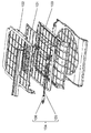
図9は、特許文献1に記載の従来の空気調和機のフィルタ101およびフィルタ駆動軸104を備えるカセットを示す分解斜視図である。
図9に示すように、特許文献1に記載のフィルタ掃除ユニットのカセットのフィルタ101は、上下方向からフィルタ保持枠102およびフィルタ保持枠103で挟み込まれ、保持される。フィルタ保持枠102、103は、四角形の形状を有し、4辺のうちの1辺が開放される。
つまり、カセットは、空気の吸い込み方向から見たとき、四角形の形状を有する。フィルタ駆動軸104は、カセットの一辺に設けられる。フィルタ駆動軸104は、フィルタ駆動軸104の両側に樹脂製の歯車形状の歯車部106と、両側の歯車部106を接続する金属製の軸部105を有する。フィルタ101は、フィルタ101の裏面に設けられるラックを有する。そして、カセットは、フィルタ101のラックと、フィルタ駆動軸104の歯車部106の歯とが噛み合うように配置構成される。
上記構成により、フィルタ駆動軸104が駆動されると、歯車部106が回転する。歯車部106の回転により、軸部105を介して、フィルタ駆動軸104の両側の歯車部106が連動して回転する。このとき、歯車部106の歯と、フィルタ101の裏面のラックとが噛み合うように配設されているため、フィルタ駆動軸104の回転とともに、フィルタ101が移動する。具体的には、フィルタ101は、フィルタ保持枠102、103の開放されている一辺の方向に向かって、スライド移動する。このとき、カセットは、スライド移動するフィルタ101と接触するように配設されるブラシなどを備える。そのため、スライド移動にともなって、ブラシとフィルタ101とが接触し、フィルタ101に付着した塵埃などが除去される。
上記のように、従来の空気調和機のフィルタ掃除ユニットは、金属製の軸部105と、樹脂製の歯車部106を有するフィルタ駆動軸104を備える。軸部105の両端にある歯車部106は、互いに、軸部105を介して連結され、一端側の歯車部106の回転にともなって、他端側の歯車部106も回転するように構成される。
しかしながら、カセットのフィルタ保持枠102、103や歯車部106は、樹脂材料での成型が可能であるが、軸部105は、金属材料で成型する必要がある。つまり、金属製の部品と樹脂製の部品の2種類の部品を、予め用意する必要がある。一般的に、金属製の部品は、樹脂製の部品に比べて、高価である。また、軸部105の両端に、それぞれ歯車部106を接続する必要がある。さらに、歯車部106の装着時においては、軸部105の両端に設けられた歯車部106の歯の位置が、互いに揃うように軸部105に接続する必要がある。そのため、歯車部106と軸部105との接続時において、製造ステップが、さらに増加する。
以上のように、従来の空気調和機のフィルタ駆動軸104およびフィルタ掃除ユニットは、コスト面および製造面において、さらなる改善が要望される。
本発明は、低コストのフィルタの駆動軸とそれを用いたフィルタ掃除ユニットを提供する。
本発明の駆動軸は、実質的に半円状の断面を有する第1軸部と、第1軸部の一端に設けられる第1歯車を含む第1駆動軸部材と、実質的に半円状の断面を有する第2軸部と、第2軸部の一端に設けられる第2歯車を含む第2駆動軸部材を備える。第1軸部および第2軸部は、実質的に半円状の断面の弧を含む曲面部と、実質的に半円状の断面の弦を含む平面部を有する。そして、駆動軸は、第1駆動軸部材の平面部と第2駆動軸部材の平面部とを、互いに重ね合わすことにより、実質的に円柱状で構成される軸部を有する。
上記構成によれば、金属製の部品を用いず、樹脂材料で、駆動軸を一体成型により形成できる。これにより、駆動軸を低コストで生産できるとともに、第1歯車と第2歯車とのねじれの発生を低減できる。
また、本発明のフィルタ掃除ユニットは、上記駆動軸と、第1歯車および第2歯車と噛み合う突起部を一方の面に有するフィルタと、フィルタをスライド可能に保持するフィルタ保持部を備える。
上記構成によれば、低コストの駆動軸を用いることにより、フィルタ掃除ユニットを安価に提供できる。
以下、図面を参照しながら、実施の形態を詳細に説明する。但し、必要以上に詳細な説明は、省略する場合がある。例えば、既によく知られた事項の詳細説明、または実質的に同一の構成に対する重複説明を省略する場合がある。これは、以下の説明が必要以上に冗長になるのを避け、当業者の理解を容易にするためである。
なお、添付図面および以下の説明は、当業者が本開示を十分に理解するために提供されるのであって、これらにより請求の範囲に記載の主題を限定することを意図していない。
(実施の形態)
以下、本発明の実施の形態の空気調和機について、図1を用いて、説明する。
以下、本発明の実施の形態の空気調和機について、図1を用いて、説明する。
なお、以降では、後述する上面開口部2b側を上方、その反対側を下方、前面パネル3側を前方、その反対側を後方として、説明する。さらに、前方から前面パネル3を見て、左側(奥行側)を左方、右側(手前側)を右方として、説明する。
図1は、本実施の形態に係る駆動軸14およびそれを用いたフィルタ掃除ユニット11を組み込んだ空気調和機の室内機1の断面を示す図である。
図1に示すように、空気調和機の室内機1は、本体2、本体2の前面側に開口する前面開口部2a、本体2の上面側に開口する上面開口部2bなどを備える。前面開口部2aは、開閉自在に構成される前面パネル3で覆われる。なお、前面パネル3は、通常、閉じた状態で保持され、使用者が、例えばメンテナンス作業をする際などにおいて、開かれる。
本体2は、本体2の内部に配設される、ファン5、熱交換器4、フィルタ10、フィルタ掃除ユニット11などを備える。ファン5は、駆動時の回転により、室内の空気を上面開口部2bから内部に吸い込む。そして、ファン5は、吸い込んだ空気を、通風路9を通って、本体2の下方に設けられた吹出口6から、室内に吹き出す。
熱交換器4は、前後方向の断面において、略コの字(コの字を含む)の形状で構成され、ファン5の周辺を取り囲むように配設される。そのため、吹出口6側の通風路9の部分には、熱交換器が設けられない。そして、上面開口部2bから吸い込まれた空気は、熱交換器4内を通流する冷媒と熱交換される。熱交換された空気は、ファン5の回転により、吹出口6から吹き出される。これにより、空気調和機を介して、室内などの空気調和が実行される。
つまり、吹出口6は、室内に空気を吹き出すように、空気調和機に設けられる。吹出口6は、周辺に配設される、上下風向変更羽根7、左右風向変更羽根8などを有する。上下風向変更羽根7は、吹出口6を開閉するとともに、空気の吹き出し方向を上下に変更する。左右風向変更羽根8は、空気の吹き出し方向を左右に変更する。
具体的には、使用者により、空気調和機の空調運転が開始されると、上下風向変更羽根7が開くように制御され、吹出口6が開放される。吹出口6が開放された状態で、ファン5が駆動されると、室内の空気が、上面開口部2bを介して、室内機1の内部に取り入れられる。取り入れられた空気は、熱交換器4で熱交換される。熱交換された空気は、ファン5の送風方向の後方下流側に形成される通風路9を通過して、吹出口6から室内に吹き出される。これにより、室内などの空気調和が実行される。
フィルタ10は、本体2の上面開口部2bと熱交換器4との間に設けられる。フィルタ10は、前面開口部2aおよび上面開口部2bなどから取り入れられた室内の空気中に含まれる塵埃などを付着させて、除去する。なお、フィルタ10は、枠体部分と、枠体部分に保持される網部分を含んで構成される。
さらに、本実施の形態の空気調和機は、上記駆動軸14を含むフィルタ掃除ユニット11を備える。フィルタ掃除ユニット11は、フィルタ10の網部分に付着した塵埃を、自動的に清掃する機能を有する。
以下、空気調和機のフィルタ掃除ユニット11について、図2から図4を用いて、説明する。
図2は、同空気調和機の室内機1のフィルタ掃除ユニット11の断面を示す図である。図3は、フィルタを省略したフィルタ掃除ユニット11を示す斜視図である。図4は、フィルタ掃除ユニット11の駆動軸14周辺の部分拡大断面を示す図である。
図2から図4に示すように、フィルタ掃除ユニット11は、フィルタ10、フィルタ保持部12、駆動軸14、ブラシ15、塵受け部材16、ファンなどで例示される排気装置(図示せず)などで構成される。フィルタ保持部12は、フィルタ10を上下に挟み込むように構成され、フィルタ10をスライド自在に保持する。駆動軸14は、フィルタ10をスライド搬送させる。ブラシ15は、フィルタ10に付着した塵埃などを掻き落とし、除去する。塵受け部材16は、ブラシ15で除去した塵埃などを受け止めて溜める。排気装置は、塵受け部材16に溜まっている塵埃などを、所定の場所に排出する。
具体的には、フィルタ保持部12は、図2に示すように、フィルタ10を保持するための通常ガイド部12A、折返しガイド部12Bなどを含む。そして、後述する駆動軸14の回転動作により、フィルタ10は、通常ガイド部12Aから折返しガイド部12Bへ、または、その逆向きの折返しガイド部12Bから通常ガイド部12Aへ、スライド搬送される。
駆動軸14は、図4に示すように、室内機1の幅方向(図1では奥行方向)に延在する軸部17(図5参照)、軸部17の両端に設けられ、歯車部18を構成する第1歯車18aおよび第2歯車18bなどを備える。第1歯車18aおよび第2歯車18bは、円筒状で構成され、円周全域に亘って、一体成型により形成される歯を有する。軸部17、第1歯車18aおよび第2歯車18bは、略同径(同径を含む)で形成される。さらに、第1歯車18aおよび第2歯車18bに形成される歯は、同じ数および同じピッチで設けられる。
一方、フィルタ10は、図2に示すように、裏面側に形成され、突起部を構成するラック歯19を備える。フィルタ10のラック歯19は、フィルタ10を軸部17に架け回した際、第1歯車18aおよび第2歯車18bの円周全域に形成される歯と係合するように形成される。これにより、駆動軸14が回転すると、フィルタ10がスライド搬送される。なお、駆動軸14の詳細な構成については、後述する。
ブラシ15は、図4に示すように、駆動軸14の下方で、駆動軸14に沿って室内機1の幅方向(図4の奥行方向)に設けられる。ブラシ15は、上下方向に反転自在に構成される。例えばフィルタ10の掃除時においては、ブラシ15は、フィルタ10と当接するように、上向きに配置される。これにより、フィルタ10の表面に付着している塵埃が、ブラシ15で掻き落とされ、除去される。
塵受け部材16は、図2に示すように、ブラシ15の下方を覆うように、ブラシ15に沿って、室内機1の幅方向(図2の奥行方向)に配設される。塵受け部材16は、図示しない排気装置に連通され、内部に溜まる塵埃などを所定の場所に排出可能に構成される。
さらに、塵受け部材16は、内部で、かつブラシ15の下方部分に設けられる、例えばゴムなどの弾性体などからなるブレード20を備える。ブレード20は、ブラシ15を下向きに反転させた状態において、フィルタ10からブラシ15に付着した塵埃などを除去する。これにより、塵受け部材16内に、除去された塵埃などが蓄積され、排出される。
以上のように、フィルタ掃除ユニット11は構成される。
以下、上記構成のフィルタ掃除ユニット11のフィルタ10の掃除動作について、説明する。
まず、フィルタ10は、空気調和機の通常の使用時において、図1に示すように、フィルタ保持部12の通常ガイド部12A内に配置される。フィルタ10は、上面開口部2bから取り入れられた室内の空気中に含まれる塵埃などを除去する。
つぎに、使用者の操作により、フィルタ10の掃除動作の開始が指示されると、ブラシ15は、フィルタ10の表面(ラック歯19の形成面の反対側の面;塵埃が付着する面)に当接するように、上向きに配置される。そして、例えばモータなどの駆動源により、駆動軸14が回転駆動される。これにより、第1歯車18aおよび第2歯車18bが正方向(図2では反時計回り)に回転し、フィルタ10が、通常ガイド部12Aから、折返しガイド部12Bへスライド搬送される。そして、フィルタ10は、一端が、折返しガイド部12Bと通常ガイド部12Aとの合流部分12Cを通過して、通常ガイド部12Aの最終端に到達する。最終端に到達すると、第1歯車18aおよび第2歯車18bが逆方向(図2では時計回り)に回転する。これにより、フィルタ10は、折返しガイド部12Bから、通常ガイド部12Aへとスライド搬送される。
そして、上記フィルタ10のスライド搬送時において、フィルタ10に付着した塵埃などが、接触配置されるブラシ15により、掻き落とされ、除去される。さらに、フィルタ10からブラシ15に付着した塵埃は、ブラシ15の下方への反転により、ブレード20と当接して、ブラシ15から除去される。フィルタ10およびブラシ15から除去された塵埃などは、落下して、塵受け部材16で受け止められる。そして、塵受け部材16内の塵埃などは、例えば所定時間(例えば、24時間)ごとに駆動される排気装置により、例えば屋外などの所定の場所へと排出される。
以上のように、フィルタ掃除ユニット11のフィルタ10の掃除動作が実行される。
つぎに、フィルタ10をスライド搬送する駆動軸14の構成について、図5から図8を用いて、説明する。
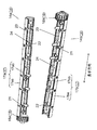
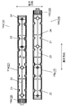
図5は、同実施の形態に係る駆動軸14の正面図である。図6は、駆動軸14の分解斜視図である。図7は、駆動軸14の内部を示す分解斜視図である。図8は、駆動軸14の分解平面図である。
図5から図8に示すように、駆動軸14は、上述したように、軸部17、歯車部18などを備える。軸部17は、第1軸部17a、第2軸部17bなどを含む。第1軸部17aおよび第2軸部17bは、後述する平面部17ab、17bbおよび曲面部17aa、17baを有する。歯車部18は、第1歯車18a、第2歯車18bなどを含み、軸部17の両端に配設される。そして、軸部17は、第1軸部17aの平面部17abと、第2軸部17bの平面部17bbとが、互いに重ね合うように配置されて、構成される。
具体的には、まず、第1軸部17aと第1歯車18aとは、例えばABS樹脂などの樹脂材料で一体成型され、第1駆動軸部材14aを構成する。同様に、第2軸部17bと第2歯車18bとは、例えばABSなどの樹脂材料で一体成型され、第2駆動軸部材14bを構成する。そして、駆動軸14は、図6から図8に示すように、長手方向に沿って、半割にした一対の半割一体部品である、第1駆動軸部材14aと第2駆動軸部材14bとの接合により、形成される。
より詳しく説明すると、第1駆動軸部材14aおよび第2駆動軸部材14bは、軸部17が半割された第1軸部17aおよび第2軸部17bを有する。つまり、第1駆動軸部材14aは第1軸部17aを含んで形成され、第2駆動軸部材14bは第2軸部17bを含んで形成される。
そして、第1駆動軸部材14aは、第1軸部17aと、第1軸部17aの一端(図6の左側)に一体成型した完成歯車状態の第1歯車18aとから構成される。このとき、第1軸部17aは、回転方向に平行な、半円状の形状の断面を有する。そのため、第1軸部17aは、上記断面における弧を含む曲面部17aaと、弦を含む平面部17abとを含む。さらに、第1軸部17aは、第1軸部17aの長手方向の中心を境に、左側(第1歯車18a側)に設けられる複数の凸部21と、右側に設けられる複数の凹部22を備える。複数の凸部21は、第1軸部17aの平面部17abから突き出るように設けられる。複数の凹部22は、平面部17abから曲面部17aaへ食い込むように設けられる。
同様に、第2駆動軸部材14bは、第2軸部17bと、第2軸部17bの他端(第1駆動軸部材14aの反対側;図6の右側)に一体成型した完成歯車状態の第2歯車18bとから構成される。このとき、第2軸部17bは、回転方向に平行な、半円状の形状の断面を有する。そのため、第2軸部17bは、上記断面における弧を含む曲面部17baと、弦を含む平面部17bbとを含む。さらに、第2軸部17bは、第1軸部17aと同様に、第2軸部17bの長手方向の中心を境に、右側(第2歯車18b側)に設けられる複数の凸部21と、左側に設けられる複数の凹部22を備える。複数の凸部21は、平面部17bbから突き出るように設けられる。複数の凹部22は、平面部17bbから曲面部17baへ食い込むように設けられる。
そして、第1軸部17aの凸部21を、対応する第2軸部17bの凹部22に嵌合させる。これにより、第1軸部17aと第2軸部17bとが接合して一体化し、駆動軸14が形成される。なお、第1軸部17aの凹部22を、対応する第2軸部17bの凸部21に嵌合させて、駆動軸14を形成してもよい。
ここで、図5から図8は、第1軸部17aの凸部21が第2軸部17bの凹部22に、第2軸部17bの凸部21が第1軸部17aの凹部22に、それぞれ嵌合して形成された駆動軸14を示している。
以上により、それぞれ第1歯車18aおよび第2歯車18bを両端に含む第1軸部17aおよび第2軸部17bからなる軸部17を備える駆動軸14が構成される。
つまり、本実施の形態の第1駆動軸部材14aは、第1軸部17aの長手方向の略中心(中心を含む)を境として、第1歯車18aを有する側に複数の凹部22を設け、第1歯車18aを有さない側に複数の凸部21を設けている。同様に、第2駆動軸部材14bは、第2軸部17bの長手方向の略中心(中心を含む)を境として、第2歯車18bを有する側に複数の凹部22を設け、第2歯車18bを有さない側に複数の凸部21を設けている。
これにより、第1駆動軸部材14aおよび第2駆動軸部材14bが、同一形状の部材で構成される。そして、一方の第1駆動軸部材14aの凸部21を、他方の第2駆動軸部材14bの凹部22に嵌合させて接合する。これにより、軸部17の両端に、第1歯車18aおよび第2歯車18bを備える駆動軸14が形成される。
また、駆動軸14の軸部17は、第1軸部17aと第2軸部17bとを嵌合した状態において、中空形状で構成される。つまり、第1軸部17aは、平面部17abから、曲面部17aaにかけて開口する形状で形成される。同様に、第2軸部17bは、平面部17bbから、曲面部17baにかけて開口する形状で形成される。これにより、軸部17の内部が中空形状で形成される。
さらに、第1駆動軸部材14aは、曲面部17aaの内部に設けられる、第1軸部17aの内面軸線方向(長手方向)に沿って形成される第一補強リブ23と、第一補強リブ23と交差する方向(短手方向)に形成される複数の第二補強リブ24を有する。同様に、第2駆動軸部材14bは、曲面部17baの内部に設けられる、第2軸部17bの内面軸線方向に沿って形成される第一補強リブ23と、第一補強リブ23と交差する方向に形成される複数の第二補強リブ24を有する。これにより、駆動軸14の機械的強度が向上するとともに、駆動軸14のねじれに対する強度が向上する。その結果、フィルタ10のスライド搬送時の負荷変動などに起因する、駆動軸14のねじれの発生を抑制できる。
以上のように、駆動軸14は構成される。
上述したように、本実施の形態の駆動軸14は、第1軸部17aおよび第1歯車18aが樹脂材料の一体成型で形成される第1駆動軸部材14aと、同様に形成される第2駆動軸部材14bとで構成される。そのため、従来の金属部品と樹脂部品の組み合わせにより形成されるフィルタ駆動軸と比べて、材料費を低減できる。これにより、低コストで駆動軸14を形成できる。
また、駆動軸14は、軸部17を半割形状で形成した第1駆動軸部材14aおよび第2駆動軸部材14bの半割面である平面部17ab、17bbに設けた凸部21と凹部22を嵌合させるだけで一体化できる。そのため、駆動軸14の組み立て性が向上するとともに、安価な駆動軸14を提供できる。
そして、本実施の形態のフィルタ掃除ユニット11は、低コストで組み立て性に優れた駆動軸14を用いて構成できる。そのため、フィルタ掃除ユニット11を低コストで実現できる。
また、軸部17は、中空形状の第1軸部17aおよび第2軸部17bを接合して、中空形状で形成される。そのため、軸部17を形成する樹脂材料の費用の低減により、さらに安価に軸部17を提供できる。同時に、駆動軸14の軽量化を図ることができる。これにより、軸部17の組み立て時における、部品としての取り扱い性が、さらに向上する。
また、駆動軸14を構成する一対の第1駆動軸部材14aおよび第2駆動軸部材14bは、構成部材である、第1歯車18a、第2歯車18b、凹部22および凸部21が、左右対称となるように配置される。これにより、第1駆動軸部材14aおよび第2駆動軸部材14bを、同一の形状の部品で構成できるため、部品管理が容易になる。また、駆動軸14の組み立て間違いなどを、防止できる。さらに、第1駆動軸部材14aおよび第2駆動軸部材14bを一体成型する金型を、一種類で構成できる。そのため、大幅な生産コストの低減とともに、さらに安価な駆動軸14を実現できる。
また、駆動軸14の軸部17は、中空形状で形成される。そのため、回転軸方向に沿った長さが長い柱状の中実の軸部に比べて、その肉厚の厚みに起因する、成型時のヒケによる軸線たわみなどの発生を低減できる。これにより、樹脂製の軸部17でフィルタの駆動軸14を構成しても、軸部17の軸線を直線状に安定して維持できる。
さらに、中空形状の軸部17を構成する第1軸部17aおよび第2軸部17bは、内面軸線方向(長手方向)に沿って形成される第一補強リブ23と、第一補強リブ23と交差する方向(短手方向)に形成される複数の第二補強リブ24を有する。これにより、中空形状でも、柱状の中実の軸部と同程度の剛性を持たせることができる。その結果、軸部17の軸線のたわみの発生を効果的に抑制して、剛性の高い駆動軸14を実現できる。
また、第1駆動軸部材14aと第2駆動軸部材14bは、回転駆動時において、第1軸部17aの平面部17abおよび第2軸部17bの平面部17bbを介して、トルクが伝達される。そのため、第1歯車18a側にのみ駆動用のモータを設けて駆動する場合でも、モータの駆動力が、第1軸部17aの平面部17abおよび第2軸部17bの平面部17bbを介して、確実に伝達され、第2歯車18bにトルクが伝わる。これにより、フィルタ10の駆動に駆動軸14を用いた場合でも、第1歯車18aと第2歯車18bとの撓みや、ずれを、より確実に低減できる。
そして、本実施の形態のフィルタ掃除ユニット11は、上記構成を有する駆動軸14を備える。そのため、撓みなどの無い平面性の高い軸部17により、軸部17に架け回すフィルタ10の平面度を上げることができる。これにより、ブラシ15を、フィルタ10の幅全域に亘って、より確実に接触させることができる。その結果、ブラシ15によるフィルタ10の掃除性能を、さらに向上させることができる。
また、駆動軸14は、軸部17を構成する第1軸部17aおよび第2軸部17bが半割形状で形成される。一方、歯車部18を構成する第1歯車18aおよび第2歯車18bは、半割形状ではなく、円筒状の完成歯車で形成される。そのため、フィルタ10のスライド搬送時において、何らかの原因で歯車部18に過大なトルクが加わっても、歯車部18の分離損壊などが発生しにくい。これにより、長期にわたって高い信頼性を維持できる駆動軸14を実現できる。
つまり、例えば第1歯車および第2歯車を、軸部17と同様に、半割形状で接合して一体化した場合、歯車部に過大なトルクが加わると、歯車部が半割状態に分離損壊する懸念がある。そこで、本実施の形態の駆動軸14は、第1歯車18aと第2歯車18bを、それぞれ一体物の完成品で構成する。これにより、半割形状を組み合わせた歯車部に発生しやすい分離損壊などを、未然に防止できる。その結果、さらに信頼性の高い駆動軸14を実現できる。
そして、本実施の形態のフィルタ掃除ユニット11は、上記構成を有する駆動軸14を備える。そのため、駆動軸14の歯車部18の分離損壊などの発生を心配する必要がない。これにより、信頼性の高いフィルタ掃除ユニット11を実現できる。
以上、本発明に係るフィルタ10の駆動軸14およびそれを用いたフィルタ掃除ユニット11について、上記実施の形態を用いて説明したが、本発明はこれに限定されるものではない。
例えば、上記実施の形態では、フィルタ10の駆動軸14およびフィルタ掃除ユニット11を用いた機器として、空気調和機を例に説明したが、これに限られない。機器は、例えば空気清浄機でもよい。つまり、搬送可能なフィルタを用いる機器であれば、特に制限されず、どのような機器でもよい。
また、今回開示した実施の形態は、すべての点で例示であって制限的なものではないと考えられるべきである。そのため、本発明の範囲は、請求の範囲によって示され、請求の範囲と均等の意味および範囲内でのすべての変更が含まれるものである。
以上で説明したように、本発明の駆動軸は、実質的に半円状の断面を有する第1軸部と、第1軸部の一端に設けられる第1歯車を含む第1駆動軸部材と、実質的に半円状の断面を有する第2軸部と、第2軸部の一端に設けられる第2歯車を含む第2駆動軸部材を備える。第1軸部および第2軸部は、実質的に半円状の断面の弧を含む曲面部と実質的に半円状の断面の弦を含む平面部を有する。そして、駆動軸は、第1駆動軸部材の平面部と第2駆動軸部材の平面部とを、互いに重ね合わすことにより、実質的に円柱状で構成される軸部を有する。
上記構成によれば、軸部と歯車とを樹脂材料の一体成型で形成できる。そのため、金属部品と樹脂部品との組み合わせによる駆動軸に比べて、材料費を低減できる。また、駆動軸は、軸部の平面部を重ね合わることにより、一体化して形成される。そのため、組み立て性に優れ、安価な駆動軸を提供できる。
また、本発明の駆動軸は、軸部が中空形状で構成されることが望ましい。
この構成によれば、駆動軸の軸部の材料費を低減できるとともに、フィルタの駆動軸の軽量化を図ることができる。そのため、安価で利便性の高い駆動軸を提供できる。さらに、回転軸の軸部に沿った長さが長い形状の場合における、中実の軸部の構成で生じやすいヒケによる軸線たわみなどの発生を低減できる。これにより、軸部を樹脂製としても、良好なフィルタの駆動性能が得られる駆動軸を提供できる。
また、本発明の駆動軸の第1歯車は、第1駆動軸部材において、円周全域に設けられる歯を有する構成が望ましい。
この構成によれば、第1歯車は、第1駆動軸部材において、一体物の完成歯車で構成される。そのため、第1歯車に大きなトルクが加わる場合でも、第1歯車の分離や損壊を低減できる。さらに、例えばフィルタ掃除ユニットに組み込まれた状態において、第1歯車とフィルタとの噛み合わせが良好になる。そのため、第1歯車の位置に対して、フィルタが滑るなどの現象の発生を低減できる。
また、本発明の駆動軸の第2歯車は、第2駆動軸部材において、円周全域に設けられる歯を有する構成が望ましい。
この構成によれば、第2歯車も、第1歯車と同様に、一体物の完成歯車で構成される。これにより、より信頼性の高い駆動軸を提供できる。
また、本発明の駆動軸は、第1軸部の平面部および第2軸部の平面部の各々が、凸部と凹部とを備え、対応する第1軸部の凸部と第2軸部の凹部とが嵌合される構成が望ましい。
この構成によれば、駆動軸の製造時において、対応する凸部と凹部とに基づいて、2つの部材を容易に組み合わせて製造できる。これにより、駆動軸を、生産性良く、容易に製造できる。その結果、さらに安価に駆動軸を実現できる。
また、本発明のフィルタ掃除ユニットは、上記駆動軸と、第1歯車および第2歯車と噛み合う突起部を一方の面に有するフィルタと、フィルタをスライド可能に保持するフィルタ保持部を備える。
この構成によれば、フィルタ掃除ユニットに、安価な駆動軸を用いることができる。これにより、フィルタ掃除ユニットのコストを低減できる。さらに、安価なフィルタ掃除ユニットの提供により、低コストの空気調和機などの機器を実現できる。
本発明は、フィルタの駆動軸を安価に提供できるとともに、これを用いたフィルタ掃除ユニットも安価に提供できる。そのため、駆動軸およびフィルタ掃除ユニットは、家庭用および業務用の空気調和機に広く適用できる。
1 室内機
2 本体
2a 前面開口部
2b 上面開口部
3 前面パネル
4 熱交換器
5 ファン
6 吹出口
7 上下風向変更羽根
8 左右風向変更羽根
9 通風路
10,101 フィルタ
11 フィルタ掃除ユニット
12 フィルタ保持部
12A 通常ガイド部
12B 折返しガイド部
12C 合流部分
14 駆動軸
14a 第1駆動軸部材
14b 第2駆動軸部材
15 ブラシ
16 塵受け部材
17,105 軸部
17a 第1軸部
17aa,17ba 曲面部
17ab,17bb 平面部
17b 第2軸部
18,106 歯車部
18a 第1歯車
18b 第2歯車
19 ラック歯(突起部)
20 ブレード
21 凸部
22 凹部
23 第一補強リブ
24 第二補強リブ
102,103 フィルタ保持枠
104 フィルタ駆動軸
2 本体
2a 前面開口部
2b 上面開口部
3 前面パネル
4 熱交換器
5 ファン
6 吹出口
7 上下風向変更羽根
8 左右風向変更羽根
9 通風路
10,101 フィルタ
11 フィルタ掃除ユニット
12 フィルタ保持部
12A 通常ガイド部
12B 折返しガイド部
12C 合流部分
14 駆動軸
14a 第1駆動軸部材
14b 第2駆動軸部材
15 ブラシ
16 塵受け部材
17,105 軸部
17a 第1軸部
17aa,17ba 曲面部
17ab,17bb 平面部
17b 第2軸部
18,106 歯車部
18a 第1歯車
18b 第2歯車
19 ラック歯(突起部)
20 ブレード
21 凸部
22 凹部
23 第一補強リブ
24 第二補強リブ
102,103 フィルタ保持枠
104 フィルタ駆動軸
Claims (6)
- 実質的に半円状の断面を有する第1軸部と、前記第1軸部の一端に設けられる第1歯車と、を含む第1駆動軸部材と、
実質的に半円状の断面を有する第2軸部と、前記第2軸部の一端に設けられる第2歯車と、を含む第2駆動軸部材と、を備え、
前記第1軸部および前記第2軸部は、
実質的に半円状の断面の弧を含む曲面部と、実質的に半円状の断面の弦を含む平面部と、を有し、
前記第1駆動軸部材の前記平面部と前記第2駆動軸部材の前記平面部とを、互いに重ね合わすことにより、実質的に円柱状で構成される軸部を有する、
駆動軸。 - 前記軸部は、中空形状である、
請求項1に記載の駆動軸。 - 前記第1歯車は、第1駆動軸部材において、円周全域に設けられる歯を有する、
請求項1または請求項2のいずれか1項に記載の駆動軸。 - 前記第2歯車は、第2駆動軸部材において、円周全域に設けられる歯を有する、
請求項1から請求項3のいずれか1項に記載の駆動軸。 - 前記第1軸部の前記平面部および前記第2軸部の前記平面部の各々は、凸部と凹部とを備え、
前記第1軸部の前記凸部と前記第2軸部の前記凹部とが嵌合するように構成される、
請求項1から請求項4のいずれか1項に記載の駆動軸。 - 請求項1から請求項5のいずれか1項に記載の駆動軸と、
前記第1歯車および前記第2歯車と噛み合う突起部を一方の面に有するフィルタと、
前記フィルタをスライド可能に保持するフィルタ保持部と、を備える、
フィルタ掃除ユニット。
Applications Claiming Priority (2)
| Application Number | Priority Date | Filing Date | Title |
|---|---|---|---|
| JP2019028977A JP7300577B2 (ja) | 2019-02-21 | 2019-02-21 | 駆動軸及びそれを用いたフィルタ掃除ユニット |
| JP2019-028977 | 2019-12-26 |
Publications (1)
| Publication Number | Publication Date |
|---|---|
| WO2020171027A1 true WO2020171027A1 (ja) | 2020-08-27 |
Family
ID=72143682
Family Applications (1)
| Application Number | Title | Priority Date | Filing Date |
|---|---|---|---|
| PCT/JP2020/006136 Ceased WO2020171027A1 (ja) | 2019-02-21 | 2020-02-17 | 駆動軸およびそれを用いたフィルタ掃除ユニット |
Country Status (2)
| Country | Link |
|---|---|
| JP (1) | JP7300577B2 (ja) |
| WO (1) | WO2020171027A1 (ja) |
Citations (8)
| Publication number | Priority date | Publication date | Assignee | Title |
|---|---|---|---|---|
| JPS59121217A (ja) * | 1982-12-27 | 1984-07-13 | Canon Inc | 回転体の駆動軸 |
| JPS6363283B2 (ja) * | 1980-01-30 | 1988-12-07 | ||
| JP2008138927A (ja) * | 2006-12-01 | 2008-06-19 | Matsushita Electric Ind Co Ltd | 天井埋込形空気調和機 |
| US20100278586A1 (en) * | 2007-06-28 | 2010-11-04 | European Aeronautic Defence And Space Company Eads France | Structural connecting rod made of a composite and process for producing such a connecting rod |
| JP2016527100A (ja) * | 2013-06-05 | 2016-09-08 | ハチンソン | 複合連接棒、そのような棒を製造するための方法、及びそれを組み込んだ航空機用の天井構造又は床構造 |
| CN205939630U (zh) * | 2016-07-15 | 2017-02-08 | 广东美的制冷设备有限公司 | 滤网驱动件和空调室内机 |
| JP2018066563A (ja) * | 2018-02-06 | 2018-04-26 | 三菱電機株式会社 | 空気調和機の室内機 |
| WO2019030861A1 (ja) * | 2017-08-09 | 2019-02-14 | 三菱電機株式会社 | 空気調和機の室内機、及びこの室内機を備えた空気調和機 |
Family Cites Families (1)
| Publication number | Priority date | Publication date | Assignee | Title |
|---|---|---|---|---|
| JP6363283B1 (ja) | 2017-09-26 | 2018-07-25 | 宇部樹脂加工株式会社 | 保護カバー |
-
2019
- 2019-02-21 JP JP2019028977A patent/JP7300577B2/ja active Active
-
2020
- 2020-02-17 WO PCT/JP2020/006136 patent/WO2020171027A1/ja not_active Ceased
Patent Citations (8)
| Publication number | Priority date | Publication date | Assignee | Title |
|---|---|---|---|---|
| JPS6363283B2 (ja) * | 1980-01-30 | 1988-12-07 | ||
| JPS59121217A (ja) * | 1982-12-27 | 1984-07-13 | Canon Inc | 回転体の駆動軸 |
| JP2008138927A (ja) * | 2006-12-01 | 2008-06-19 | Matsushita Electric Ind Co Ltd | 天井埋込形空気調和機 |
| US20100278586A1 (en) * | 2007-06-28 | 2010-11-04 | European Aeronautic Defence And Space Company Eads France | Structural connecting rod made of a composite and process for producing such a connecting rod |
| JP2016527100A (ja) * | 2013-06-05 | 2016-09-08 | ハチンソン | 複合連接棒、そのような棒を製造するための方法、及びそれを組み込んだ航空機用の天井構造又は床構造 |
| CN205939630U (zh) * | 2016-07-15 | 2017-02-08 | 广东美的制冷设备有限公司 | 滤网驱动件和空调室内机 |
| WO2019030861A1 (ja) * | 2017-08-09 | 2019-02-14 | 三菱電機株式会社 | 空気調和機の室内機、及びこの室内機を備えた空気調和機 |
| JP2018066563A (ja) * | 2018-02-06 | 2018-04-26 | 三菱電機株式会社 | 空気調和機の室内機 |
Also Published As
| Publication number | Publication date |
|---|---|
| JP2020134037A (ja) | 2020-08-31 |
| JP7300577B2 (ja) | 2023-06-30 |
Similar Documents
| Publication | Publication Date | Title |
|---|---|---|
| US20090047133A1 (en) | Impeller blade for centrifugal blower, blade-supporting rotator, impeller for centrifugal blower, and method for manufacturing impeller for centrifugal blower | |
| CN103790859B (zh) | 螺旋桨式风机和具有该螺旋桨式风机的空调 | |
| CN103017308B (zh) | 一种分体落地式空调器 | |
| JP4761323B2 (ja) | 遠心ファン、成型用金型および流体送り装置 | |
| US9447790B2 (en) | Cross-flow fan | |
| JP5018594B2 (ja) | 換気装置 | |
| JP5212438B2 (ja) | フィルタ移動機構及び空調室内機 | |
| JP4878599B2 (ja) | 空気調和機の室内機 | |
| JP2007100975A (ja) | 空気調節装置 | |
| CN103075791A (zh) | 空气调节器的室内机 | |
| JP6767635B2 (ja) | 空気調和機 | |
| CN110325800A (zh) | 空气调节机 | |
| JP7300577B2 (ja) | 駆動軸及びそれを用いたフィルタ掃除ユニット | |
| JP6998506B2 (ja) | 空気調和機 | |
| CN102865625B (zh) | 空调室内机 | |
| WO2018163548A1 (ja) | 空気調和機 | |
| CN105823190A (zh) | 一种风口结构及其制造方法 | |
| JP5585318B2 (ja) | 空調室内機 | |
| JP6835259B2 (ja) | 吹出パネルおよび空調室内機 | |
| JP6754945B2 (ja) | 空気調和機 | |
| JP6998505B2 (ja) | 空気調和機 | |
| JP5345607B2 (ja) | 遠心ファン、成型用金型および流体送り装置 | |
| JP5469635B2 (ja) | 遠心ファン、成型用金型および流体送り装置 | |
| JP2019007653A (ja) | 空気調和機 | |
| CN211400037U (zh) | 散风组件及空调器 |
Legal Events
| Date | Code | Title | Description |
|---|---|---|---|
| 121 | Ep: the epo has been informed by wipo that ep was designated in this application |
Ref document number: 20760155 Country of ref document: EP Kind code of ref document: A1 |
|
| NENP | Non-entry into the national phase |
Ref country code: DE |
|
| 122 | Ep: pct application non-entry in european phase |
Ref document number: 20760155 Country of ref document: EP Kind code of ref document: A1 |