WO2020171172A1 - Dispositif de serrage hydraulique, procédé de détection de point de départ de préhension de pièce à travailler d'un dispositif de serrage hydraulique, dispositif de détection de point de départ de préhension de pièce à travailler, et procédé de préhension de pièce à travailler - Google Patents
Dispositif de serrage hydraulique, procédé de détection de point de départ de préhension de pièce à travailler d'un dispositif de serrage hydraulique, dispositif de détection de point de départ de préhension de pièce à travailler, et procédé de préhension de pièce à travailler Download PDFInfo
- Publication number
- WO2020171172A1 WO2020171172A1 PCT/JP2020/006823 JP2020006823W WO2020171172A1 WO 2020171172 A1 WO2020171172 A1 WO 2020171172A1 JP 2020006823 W JP2020006823 W JP 2020006823W WO 2020171172 A1 WO2020171172 A1 WO 2020171172A1
- Authority
- WO
- WIPO (PCT)
- Prior art keywords
- working liquid
- pressure
- start point
- piston
- clamped
- Prior art date
- Legal status (The legal status is an assumption and is not a legal conclusion. Google has not performed a legal analysis and makes no representation as to the accuracy of the status listed.)
- Ceased
Links
Images


Classifications
-
- B—PERFORMING OPERATIONS; TRANSPORTING
- B23—MACHINE TOOLS; METAL-WORKING NOT OTHERWISE PROVIDED FOR
- B23B—TURNING; BORING
- B23B31/00—Chucks; Expansion mandrels; Adaptations thereof for remote control
- B23B31/40—Expansion mandrels
-
- B—PERFORMING OPERATIONS; TRANSPORTING
- B23—MACHINE TOOLS; METAL-WORKING NOT OTHERWISE PROVIDED FOR
- B23Q—DETAILS, COMPONENTS, OR ACCESSORIES FOR MACHINE TOOLS, e.g. ARRANGEMENTS FOR COPYING OR CONTROLLING; MACHINE TOOLS IN GENERAL CHARACTERISED BY THE CONSTRUCTION OF PARTICULAR DETAILS OR COMPONENTS; COMBINATIONS OR ASSOCIATIONS OF METAL-WORKING MACHINES, NOT DIRECTED TO A PARTICULAR RESULT
- B23Q3/00—Devices holding, supporting, or positioning work or tools, of a kind normally removable from the machine
- B23Q3/12—Devices holding, supporting, or positioning work or tools, of a kind normally removable from the machine for securing to a spindle in general
- B23Q3/14—Mandrels in general
Definitions
- the present invention relates to a hydraulic clamp device for clamping (hereinafter, also referred to as gripping) a member to be clamped used in the machining field and measurement field by applying a pressure to a working liquid.
- the hydraulic clamp device includes a main body including a thin-walled tubular portion that defines a working liquid chamber, and a pressurizing portion that is provided in the main body and pressurizes the working liquid enclosed in the working liquid chamber. It is known that a thin cylindrical portion clamps a member to be clamped (hereinafter also referred to as a work) by elastically deforming radially by applying pressure to the working liquid sealed in the working liquid chamber ( See, for example, Patent Documents 1 to 3).
- ⁇ Expansion (or contraction) operation method of hydraulic clamp device is roughly divided into manual and automatic (power).
- manual operation method the operating screw of the hydraulic clamp device is rotated to apply pressure to the operating liquid to expand (or contract) the thin-walled tubular portion.
- power-based operation method the piston rod of the hydraulic clamp device is pushed by a power cylinder or the like to apply pressure to the working liquid to expand (or contract) the thin-walled tubular portion.
- the work clamped by the conventional hydraulic clamp device is generally manufactured with a specified tolerance, and therefore the actual dimensions of the clamp part vary within the specified tolerance.
- the thin cylinder portion (expansion portion) is elastically deformed in the radial direction by applying pressure to the working liquid sealed in the working liquid chamber.
- the work is fitted with the expansion part of the hydraulic clamp device with a gap, if the expansion part of the hydraulic clamp device expands, it will come into contact with the inner diameter (or outer diameter) of the clamped member.
- the thin-walled cylindrical portion takes into consideration the wall thickness of the contacted work, so that elastic deformation hardly occurs.
- a method of applying pressure to the working liquid there is a method of pushing the working liquid enclosed in the working liquid chamber with a piston or the like.At the same pushing amount, the pressure to expand only the thin-walled cylinder part and the thickness of the work piece in the thin-walled cylinder part There is a difference between the thickness and the pressure for expanding the integrated state, and the difference in the pressure value becomes the gripping force for gripping the work.
- the problem to be solved by the present invention is to provide a hydraulic clamp device capable of finding a work gripping starting point for each clamped member whose size varies.
- a hydraulic clamp device includes a first member having a first peripheral surface that forms an outer peripheral surface or an inner peripheral surface, and the first member.
- a second member having a second peripheral surface forming an inner peripheral surface or an outer peripheral surface overlapping with the peripheral surface of the first member, and the first member and the second member at a portion where they overlap each other.
- a working liquid chamber is defined by a concave portion provided on at least one of the circumferential surface of the working fluid and the second circumferential surface, and the second member is elastically deformed by the pressure of the working liquid sealed in the working liquid chamber.
- a hydraulic clamping device for clamping a member to be clamped, the pressure measuring device measuring the pressure of the working liquid enclosed in the working liquid chamber, and the working liquid chamber formed in the first member.
- a driving device having a piston chamber communicating with the piston chamber, a piston rod for driving a piston provided in the piston chamber, and an arithmetic device for calculating a work gripping start point for starting the clamping of the clamped member by the second member.
- the calculation device calculates the work gripping start point based on the pressure of the working liquid measured by the pressure measurement device and the measurement data of the stroke of the piston rod.
- the workpiece gripping start point for starting the clamping of the clamped member by the second member is calculated based on the pressure of the working liquid measured by the pressure measuring device and the measurement data of the stroke of the piston rod.
- the arithmetic device elastically deforms the second member based on measurement data indicating a relationship between a pressure of the working liquid and a stroke of the piston rod.
- Two points in the first section from the start to the lower limit of the tolerance of the clamped member, and a second point from the point where the second member becomes the same as the upper limit of the tolerance of the clamped member to the most elastic deformation.
- Straight line data is created for each of the two points in the section, and the intersection of these two straight lines is used as the work gripping start point.
- the two points in the first section from the start of elastic deformation of the second member to the lower limit of the tolerance of the clamped member and the second member become the same as the upper limit of the tolerance of the clamped member. It is possible to accurately calculate the work gripping start point by creating straight line data at each of the two points in the second section from the point to the most elastic deformation and setting the intersection of these two straight lines as the work gripping start point. it can.
- the arithmetic device calculates elastically the second member to start elastic deformation based on measurement data indicating the relationship between the pressure of the working liquid and the stroke of the piston rod. From the point at which the second member becomes the same as the upper limit of the tolerance of the clamped member to the most elastically deformed second section of the clamped member to the lower limit of the tolerance of the clamped member.
- Each straight line data is calculated by the linear regression method, and the intersection of these two straight lines is set as the work gripping start point.
- the measurement data indicating the relationship between the pressure of the hydraulic fluid and the stroke of the piston rod is obtained from the first section from the elastic deformation of the second member to the lower limit of the tolerance of the clamped member, Line data is calculated by the linear regression method in each section of the second section from the point where the second member becomes the same as the upper limit of the tolerance of the clamped member to the most elastic deformation, and the intersection of these two straight lines.
- the arithmetic unit correlates the pressure of the working liquid and the stroke of the piston rod by a linear function after the second member starts elastic deformation.
- the point at which the rate of increase in pressure in the working liquid chamber in the measured data indicating the relationship is changed is the work gripping start point.
- the point at which the pressure increase rate in the working fluid chamber of the measurement data indicating the correlation between the pressure of the working fluid and the stroke of the piston rod changes after the second member starts elastic deformation is the work point. Since the gripping start point is used, the work gripping start point can be accurately calculated.
- the arithmetic device includes the pressure of the working liquid and the pressure in the section from the start of the elastic deformation of the second member to the lower limit of the tolerance of the clamped member.
- the linear function is obtained when the piston rod is stroked until the elastic deformation of the second member becomes maximum. The point where the second slope of the measurement data indicating the correlation changes more than the first slope is set as the work gripping start point.
- the arithmetic device is a section from the elastic deformation of the second member to the most elastic deformation in a state where the clamped member is not attached.
- the clamped member is attached, and the second member is the clamped member.
- the straight line data is calculated from the second measurement data showing the correlation between the pressure of the working fluid and the stroke of the piston rod by a linear function in the section from the point where the upper limit of the tolerance becomes the same as the maximum elastic deformation. Then, the intersection of these two straight lines is set as the work gripping start point.
- the pressure of the working liquid and the stroke of the piston rod are primary in the section from the elastic deformation of the second member to the most elastic deformation in the state where the clamped member is not attached.
- the first measurement data showing the correlation by the function and the working liquid in the section from the point where the second member is the same as the upper limit of the tolerance of the clamped member to the most elastically deformed state with the clamped member attached.
- the straight line data is calculated from the second measurement data indicating the correlation between the pressure of 1 and the stroke of the piston rod by a linear function, and the intersection of these two straight lines is set as the work gripping start point. Can be calculated accurately.
- the arithmetic device is a section from a time when the second member starts elastic deformation to a time when the second member is most elastically deformed in a state where the clamped member is not attached.
- the piston rod In the state where the clamped member is attached, the piston rod has the maximum stroke with respect to the inclination of the first measurement data indicating the correlation between the pressure of the working liquid and the stroke of the piston rod by a linear function.
- the point at which the slope of the second measurement data, which shows the correlation between the pressure of the hydraulic fluid and the stroke of the piston rod when the stroke is made up to a linear function, is greater than the slope of the first measurement data. Set as the work grip start point.
- the pressure of the working liquid and the stroke of the piston rod are primary in the section from the elastic deformation of the second member to the most elastic deformation in the state where the clamped member is not attached.
- the pressure of the working liquid and the stroke of the piston rod when the piston rod is stroked to the maximum stroke with the clamped member attached are 1 with respect to the inclination of the first measurement data indicating the correlation by the function. Since the point at which the slope of the second measurement data indicating the correlation by the following function changes more than the slope of the first measurement data is set as the work gripping start point, the work gripping start point can be accurately calculated. ..
- the hydraulic clamp device preferably elastically deforms the second member with reference to the workpiece gripping start point so that a predetermined gripping force is obtained with respect to the clamped member. Further, a gripping force control device for controlling the pressure of is provided.
- the gripping force control device further controls the pressure of the working liquid such that the second member is elastically deformed with the workpiece gripping start point as a reference and a predetermined gripping force is obtained with respect to the clamped member. Since it is provided, the gripping force with respect to the clamped member can be set to a predetermined value. As a result, it becomes possible to clamp each clamped member whose size varies within the tolerance with the same amount of gripping force.
- the hydraulic clamp device preferably includes a first member having a first peripheral surface forming an outer peripheral surface or an inner peripheral surface, and an inner peripheral surface or an outer peripheral surface overlapping with the first peripheral surface.
- a second member having a second peripheral surface formed therein, and at least a portion of the first peripheral surface and the second peripheral surface in a portion where the first member and the second member overlap each other.
- a hydraulic clamp device that clamps a member to be clamped by elastically deforming the second member due to the pressure of the working liquid enclosed in the working liquid chamber is defined by a recess provided on one side.
- a calculation device for calculating a work gripping start point for starting clamping of the clamped member by the second member, and elastically deforming the second member with the work gripping start point as a reference, And a gripping force control device that controls the pressure of the working liquid so that a predetermined gripping force is obtained with respect to the clamp member.
- the gripping force control device further controls the pressure of the working liquid such that the second member is elastically deformed with the workpiece gripping start point as a reference and a predetermined gripping force is obtained with respect to the clamped member. Since it is provided, the gripping force with respect to the clamped member can be set to a predetermined value. As a result, it becomes possible to clamp each clamped member whose size varies within the tolerance with the same amount of gripping force.
- a method for detecting a work gripping start point in a hydraulic clamp device is to apply a pressure to a clamp member having a working liquid chamber therein and a working liquid filled in the working liquid chamber.
- a piston, the clamp member has a wall body that defines the working liquid chamber on an inner surface side and a clamp surface on an outer surface side, and the wall is formed by pressurizing the working liquid by movement of the piston.
- a hydraulic clamp device that clamps the clamped member by pressing the clamp surface against the clamped member due to elastic deformation of the body, when the clamp surface starts contacting the clamped member Is a method for detecting a work gripping start point, wherein the work gripping start point is detected based on a pressure change of the working liquid with respect to a movement position of the piston.
- the work gripping start point can be accurately detected.
- the workpiece gripping start point is the time when the pressure rise rate of the working liquid with respect to the moving position of the piston changes with the clamped member attached to the hydraulic clamp device.
- the work gripping start point can be accurately detected.
- the work gripping start point can be accurately detected.
- the work gripping start point is detected from the change in the pressure of the working liquid with respect to the movement position of the piston with the clamped member attached.
- the work gripping start point can be accurately detected.
- the pressure of the working liquid is detected by a pressure sensor.
- the pressure of the working liquid required to detect the work gripping start point is accurately detected.
- the work gripping start point detection method preferably detects the pressure of the working liquid from a measurement value by a load cell that detects a load acting on the piston.
- the pressure of the working liquid required to detect the work gripping start point is detected from the outside.
- the workpiece gripping start point detection device in the hydraulic clamp device includes a clamp member having a working liquid chamber provided therein, and a piston for pressurizing the working liquid filled in the working liquid chamber.
- a clamp member having a working liquid chamber provided therein, and a piston for pressurizing the working liquid filled in the working liquid chamber.
- a work gripping starting point at which the clamp surface starts contacting with the clamped member is detected.
- a workpiece gripping start point based on a change in pressure of the working liquid with respect to a moving position of the piston.
- a work gripping method wherein a moving position of the piston at the work gripping start point or a pressure of the working liquid detected by the work gripping start point detecting method in the hydraulic clamp device is used.
- the gripping force of the clamped member is set on the basis of the reference.
- the clamped member can be gripped with a required gripping force even if the clamped member has dimensional variations.
- the hydraulic clamp device is moved by screwing an operating screw member provided on the first piston and the clamp member, which is moved by external pressure.
- the hydraulic clamp device which has a second piston for detecting the work gripping start point by the movement of the first piston, and based on the pressure of the working liquid at which the work gripping start point is detected, the movement of the second piston causes the target Set the gripping force of the clamp member.
- the clamped member can be gripped with a required gripping force by the external setup.
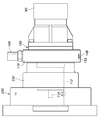
- FIG. 3 is a vertical cross-sectional view showing a main part of the hydraulic clamp device according to the first embodiment.
- FIG. 3 is a block diagram showing a control circuit of the hydraulic clamp device according to the first embodiment.
- Flowchart showing the operation of the control unit of FIG. 3 is a graph showing the relationship between the stroke (position) of the piston rod and the hydraulic pressure (pressure) in the hydraulic clamp device according to the first embodiment.
- a graph showing an example of calculating a work gripping start point based on measurement data in the first embodiment Flowchart showing another example of calculating the workpiece gripping start point based on the measurement data in the first embodiment.
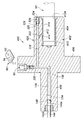
- FIG. 3 is a vertical sectional view of a hydraulic clamp device according to a third embodiment of the present invention.
- Front view of an outer setup apparatus used for carrying out a method for detecting a work gripping start point and a work gripping method according to the present invention The side view which shows the attachment state with respect to the machine tool of the hydraulic clamp apparatus which concerns on Embodiment 3.
- FIG. 4 is a vertical sectional view of a hydraulic clamp device according to a fourth embodiment of the present invention.
- Embodiment 1 of the present invention will be described with reference to FIGS. 1 to 5.
- the hydraulic clamp unit 10 is of a mandrel type and has a main body (first member) 12.
- the main body 12 includes a rod-shaped portion (mandrel) 22 formed of a round bar having a first shaft-shaped portion 16, a flange portion 18, and a second shaft-shaped portion 20 on the same axis in order in the axial direction.
- the first shaft-shaped portion 16 and the second shaft-shaped portion 20 have the same outer diameter.
- the flange portion 18 has a larger outer diameter than the first shaft-shaped portion 16 and the second shaft-shaped portion 20 and is expanded radially outward with respect to the first shaft-shaped portion 16 and the second shaft-shaped portion 20. Has been formed.
- a cylindrical body (second member) 24 forming a thin wall is fitted around the outer periphery of the first shaft portion 16.
- the cylindrical body 24 is a cylindrical wall body that defines a later-described working liquid chamber 30 on the inner surface side and a clamp surface on the outer surface side, and is an outer peripheral surface (clamp) for clamping the cylindrical member W1 to be clamped.
- a peripheral groove-shaped recess 28 is formed on the outer peripheral surface 16A of the first shaft-shaped portion 16. Between the first shaft-shaped portion 16 and the cylindrical body 24, a cross-section (cross-section orthogonal to the central axis) that extends over the entire circumference of the outer peripheral surface 16A of the first shaft-shaped portion 16 by the recess 28.
- An annular working liquid chamber 30 is defined.
- the cylindrical body 24 defines the working liquid chamber 30 on the inner surface side and the clamp surface (outer peripheral surface 24A) on the outer surface side.
- O-rings 32 for securing the liquid tightness of the working liquid chamber 30 are mounted on both sides of the outer circumferential surface 16A of the first shaft-shaped portion 16 with the working liquid chamber 30 sandwiched in the axial direction.
- the cylindrical body 24 may be liquid-tightly joined to the first shaft portion 16 by brazing or the like. In this case, the O-ring 32 becomes unnecessary.
- the rod-shaped part 22 has a piston chamber 34 that extends in the axial direction over the first shaft-shaped part 16 on the central axis.
- a piston 36 is fitted in the piston chamber 34 so as to be movable in the axial direction.
- One end of the piston chamber 34 communicates with the working liquid chamber 30 through an axial passage 38 formed in the first shaft portion 16 and a plurality of radial passages 40.
- the chamber space on the side of the passage 38 of the piston chamber 34, which is divided by the piston 36, the passages 38 and 40, and the working liquid chamber 30 form one closed space, and this closed space is filled with working oil that is working liquid. Has been done.
- a bush 42 is screwed to the second shaft 20 of the main body 12.
- a through hole 42A is formed in the bush 42 so as to penetrate in the axial direction of the central portion.
- a push rod 44 is engaged with the through hole 42A so as to be movable in the axial direction. The movement of the push rod 44 in the axial direction is transmitted to the piston 36 via the steel ball 48.
- the hydraulic clamp unit 10 has a power cylinder unit 46, which is an example of a driving device, installed on the same axis as the push rod 44.
- the power cylinder portion 46 is a drive device including a piston rod 47 for driving the piston 36, and controls a stroke of the piston rod 47 by a control signal to the power cylinder portion 46.
- the piston rod 47 moves to the right in FIG. 1 in response to the control signal, the push rod 44, the steel ball 48, and the piston 36 move in the same direction to pressurize the hydraulic oil in the hydraulic fluid chamber 30.
- the pressure of the working liquid chamber 30 is quantitatively pressurized and controlled according to the stroke of the piston rod 47.
- the power cylinder 46 is generally a hydraulic cylinder, a pneumatic cylinder, a hydraulic servo cylinder, an electric cylinder using a motor and a ball screw, or the like.
- pressurization of the hydraulic oil in the hydraulic liquid chamber 30 can be mechanized and automated.
- the pressurizing structure of the piston rod 47 is configured, and the movement of the push rod 44 causes the piston 36 to move in the piston chamber 34 to the passage 38 side (right side in FIG. 1).
- the hydraulic oil in the hydraulic liquid chamber 30 is pressurized, and the cylindrical body 24 is elastically deformed in the radial direction by this pressurization, and is radially expanded outward.
- the outer peripheral surface 24A comes into contact with the inner peripheral surface of the central hole A of the clamped member (workpiece) W1 due to the diameter expansion deformation of the cylindrical body 24 at the outer peripheral surface 24A of the cylindrical body 24,
- the member W1 to be clamped is clamped by being pressed against the inner peripheral surface.
- the clamped member W1 has a center hole A fitted on the outer periphery of the cylindrical body 24, and the cylindrical body 24 is formed on the inner peripheral surface of the center hole A by the diameter expansion deformation of the cylindrical body 24.
- the hydraulic clamp unit 10 controls the clamping force of the cylindrical member W1 to be clamped.
- a pressure sensor device (pressure measuring device) 60 is attached to the end surface 16B of the first shaft portion 16.
- the pressure sensor device 60 includes a flange portion 62, a male screw portion 64 extending from the flange portion 62 to one side, and a hexagonal portion sequentially formed on the other side of the flange portion 62.
- a hydraulic pressure measuring unit (pressure measuring device) 72 including a pressure measuring element (not shown) and a circuit board is provided in the housing 68 in a state of being sealed with oil 69.
- the male screw portion 64, the flange portion 62, and the hexagonal portion 66 are formed with a pressure introducing passage 74 that is opened at the tip of the male screw portion 64 and guides the pressure to be measured to the hydraulic pressure measuring portion 72.
- the hydraulic pressure measurement unit 72 Since the hydraulic pressure measurement unit 72 is sealed with the oil 69, the insulation reliability of the hydraulic pressure measurement unit 72 is increased, and it is less likely to be affected by the external environment, so that the hydraulic pressure measurement unit 72 can perform stable pressure measurement. Will be possible.
- a signal indicating the pressure measured by the hydraulic pressure measuring unit 72 is externally output to the cap unit 70, and in the present embodiment, is output to a wireless reader 90 (see FIG. 1) arranged in the vicinity of the hydraulic clamp unit 10.
- the wireless communication unit 76 and a power receiving unit 78 that receives power for the pressure sensor device 60 from the outside by wireless, in the present embodiment, from the wireless reader 90 described above.
- the power receiving unit 78 is a unit that is externally fed with power by a known electromagnetic induction or a radio wave in which the electric field and the magnetic field change using a wireless reader 90 using a built-in antenna (not shown). Also, power is supplied to the wireless communication unit 76.
- the first shaft portion 16 is formed with a bottomed screw hole 80 in the radial direction that opens to the end surface 16B.
- the pressure sensor device 60 is fixed to the end surface 16 ⁇ /b>B of the first shaft-shaped portion 16 by the male screw portion 64 screwing into the screw hole 80.
- an annular groove 65 is formed on the male screw portion 64 side of the flange portion 62.
- An annular rubber packing 67 is attached to the groove 65.
- the rubber packing 67 is elastically deformed and pressed against the end surface 16B of the first shaft-shaped portion 16 when the male screw portion 64 is screwed into the screw hole 80, and the rubber packing 67 is connected to the first shaft-shaped portion 16 and the pressure sensor device 60. Make a liquid-tight seal between
- the first shaft-shaped portion 16 is formed with a passage 82 communicating with the screw hole 80 in the axial direction.
- the passage 82 communicates with the axial passage 38 formed in the first shaft portion 16 and the plurality of radial passages 40.
- the screw hole 80, the passages 82, 40, and 38 are filled with the same operating oil as the expansion space of the above-mentioned closed space, and these screw holes 80, the passages 82, 40, and 38 are used as the working fluid chamber.
- the pressure of 30 is introduced to the hydraulic pressure measurement unit 72.
- the same pressure as the pressure (hydraulic pressure) of the hydraulic oil in the working liquid chamber 30 acts on the hydraulic pressure measuring unit 72, and the hydraulic pressure measuring unit 72 measures the hydraulic pressure in the working liquid chamber 30.
- the handy type wireless reader 90 is brought close to the pressure sensor device 60 of the hydraulic clamp unit 10 and the measurement button 92 of the wireless reader 90 is pressed. To be done.
- the power receiving unit 78 of the pressure sensor device 60 is supplied with power from the wireless reader 90 in a non-contact manner, and power is supplied from the power receiving unit 78 to the hydraulic pressure measuring unit 72 and the wireless communication unit 76. ..
- the hydraulic pressure measurement unit 72 and the wireless communication unit 76 become active, the hydraulic pressure measurement unit 72 measures the hydraulic pressure of the working liquid chamber 30, and the wireless communication unit 76 is measured by the hydraulic pressure measurement unit 72.
- the signal (radio wave) indicating the hydraulic pressure is output to the outside.
- the wireless reader 90 receives the radio wave output by the wireless communication unit 76, the liquid pressure of the working liquid chamber 30 is displayed on the display unit 94 of the wireless reader 90.
- the present embodiment has described the example using the wireless reader 90. However, even if the internal pressure measured by using the wired pressure sensor is transmitted to the outside, the measured value of the hydraulic pressure does not change.
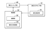
- FIG. 3 is a block diagram showing a control circuit of the hydraulic clamp device according to the first embodiment.
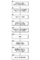
- FIG. 4 is a flowchart showing the operation of the control unit of FIG.
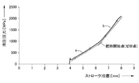
- FIG. 5 is a graph showing the relationship between the stroke (position) of the piston rod 47 that pushes the piston 36 and the hydraulic pressure (pressure) of the working liquid chamber 30 in the hydraulic clamp device according to the first embodiment.
- the operating characteristics of the hydraulic clamp unit 10 will be described. That is, the following (1), (2), and (3) are known as the operating characteristics of the hydraulic clamp device.
- (2) The pressure of the working liquid and the expansion amount of the cylindrical body 24 of the hydraulic clamp unit 10 are substantially in a correlation by a linear function.
- the relationship between the diameter of the cylindrical body 24 of the hydraulic clamp portion 10 and the stroke of the piston rod 47 can be obtained from the above correlation.
- the stroke or the hydraulic pressure of the piston rod 47 having the same diameter as the upper and lower limits of the tolerance of the gripped portion of the target clamped member W1 can be grasped as an inherent value of the hydraulic clamp portion 10. Is.
- This eigenvalue can be either measured by actually measuring the diameter of the cylindrical body 24 of the hydraulic clamp unit 10 or calculated from the design value of the hydraulic clamp unit 10.
- control circuit of the hydraulic clamp device has a control unit 50.
- the control unit 50 inputs pressure measurement data from the hydraulic pressure measurement unit 72 of the pressure sensor device 60 in the hydraulic clamp unit 10 and also inputs measurement data of the stroke of the piston rod 47 from the power cylinder unit 46.
- the control unit 50 includes a microcomputer and the like, and has a calculation unit (calculation device) 52 and a grip force control unit 54 as a grip force control device.
- the calculation unit 52 calculates a work grip start point at which the cylindrical body 24 starts clamping the member W1 to be clamped.
- the work gripping start point referred to here corresponds to the zero point of the work clamp, and the time point when the outer peripheral surface 24A of the cylindrical body 24 starts contacting the inner peripheral surface of the clamped member W1, that is, the cylindrical body 24 is clamped. It is specified by the stroke of the piston rod 47 and the pressure (hydraulic pressure) in the working liquid chamber 30 at the time of starting contact with the member W1.
- the calculation unit 52 causes the stroke of the piston rod 47 and the inside of the working liquid chamber 30 at the time when the outer peripheral surface 24A of the cylindrical body 24 starts contacting the inner peripheral surface of the clamped member W1 as the work gripping start point.
- the pressure (hydraulic pressure) is specified from these measured values. That is, the calculation unit 52 determines the workpiece grip start point (hereinafter, also referred to as a zero point) based on the measurement data of the stroke of the piston rod 47 and the measurement data of the pressure in the working liquid chamber 30 measured by the hydraulic pressure measurement unit 72. calculate.
- a power type that pushes the push rod 44 of the hydraulic clamp unit 10 with the piston rod 47 of the power cylinder unit 46 on the mounting machine side.
- the pressure sensor device 60 is connected to the working liquid chamber 30 through the passages 40 and 82 and the screw hole 80, and the pressure change inside the working liquid chamber 30 is measured by the hydraulic pressure measuring unit 72 of the pressure sensor device 60. ..
- the stroke of the piston rod 47 and the moving position of the piston 36 are equivalent.
- the stroke of the piston rod 47 which can be easily measured from the outside, is detected as the moving position of the piston 36.
- the stroke of the piston rod 47 of the power cylinder portion 46 is detected by attaching a movement amount measuring device such as a length measuring device or a displacement gauge to the piston rod 47 and measuring the movement amount of the piston rod 47 by this movement amount measuring device. ..
- a movement amount measuring device such as a length measuring device or a displacement gauge
- the stroke of the piston rod 47 can be detected by calculating the movement amount from the rotation angle of the motor and the lead of the ball screw.
- the gripping force control unit 54 uses the pressure in the working liquid chamber 30 at the workpiece gripping start point detected by the calculation unit 52 as a reference (zero point), and the pressure in the working liquid chamber 30 becomes a predetermined pressure. As described above, that is, the stroke of the piston rod 47 is controlled so that a predetermined gripping force is obtained. This gripping force can be replaced with the hydraulic pressure when the pressure in the working liquid chamber 30 is further increased from the work gripping start point.
- the cylindrical body 24 is expanded and deformed.
- the pressure (internal pressure) in the working liquid chamber 30, the amount of diametrical expansion and the cylinder stroke for pressurization and the amount of diametrical expansion have a correlation by a linear function.
- W1 is gripped, the gripping force can be grasped by the hydraulic pressure corresponding to the amount of radial expansion deformation from the work gripping start point. A specific calculation method for obtaining the work gripping start point will be described later.
- control unit 50 Next, the operation of the control unit 50 will be described with reference to FIGS. 4 and 5.
- the clamped member W1 is attached to the hydraulic clamp unit 10 (step S11). Specifically, the clamped member W1 is mounted on the outer peripheral surface 24A of the cylindrical body 24.
- step S12 the expansion (diameter expansion deformation) of the hydraulic clamp unit 10 is started (step S12). Specifically, the expansion of the cylindrical body 24 is started.
- the control unit 50 time-series the measurement data (measurement value) of the stroke of the piston rod 47 and the measurement data (measurement value) of the pressure in the working liquid chamber 30 measured by the hydraulic pressure measurement unit 72. Monitor.
- calculation unit 52 of the control unit 50 determines the workpiece grip start point (zero point) from the measurement data of the stroke of the piston rod 47 and the measurement data of the pressure inside the working liquid chamber 30 measured by the hydraulic pressure measurement unit 72. Calculate (step S14).
- control unit 50 performs feedback control so that a predetermined pressure is obtained based on the work gripping start point calculated in step S14 (step S15).
- the gripping force control unit 54 of the control unit 50 uses the measurement data of the stroke of the piston rod 47 and the measurement data of the pressure in the working liquid chamber 30 shown in FIG.
- a control signal is output to the power cylinder unit 46 so that the pressure in the chamber 30 becomes a predetermined pressure.
- the power cylinder unit 46 receives the control signal and sets the stroke value of the piston rod 47 so that the pressure in the working liquid chamber 30 becomes a predetermined pressure.
- the hydraulic clamp unit 10 elastically deforms (expands and deforms) the cylindrical body 24 based on the value of the stroke, and controls the clamped member W1 to have a predetermined pressure (gripping force). To be done.
- the control of the clamped member W1 so that a predetermined pressure (grasping force) is exerted will be described. Further, the predetermined gripping force is an arbitrary value set in advance when carrying out this control.
- the outer peripheral surface 24A of the cylindrical body 24 corresponds to the center hole A of the clamped member W1.
- the amount of diametrical expansion deformation until it comes into contact with the inner peripheral surface varies.
- the cylindrical shape is surely larger than the inner diameters of the central holes A of the plurality of clamped members W1. Since the diameter of the body 24 is determined and the clamping is performed, when a plurality of clamped members W1 are clamped, the gripping force varies.
- measurement data is obtained from the work grip start point where the outer peripheral surface 24A of the cylindrical body 24 contacts and grips the inner peripheral surface of the central hole A of the clamped member W1. Therefore, based on this measurement data, it can be seen that, for example, at what stroke the workpiece is gripped from the starting point, and at what pressure the workpiece is gripped. Therefore, it is possible to control each clamped member W1 so as to have a predetermined pressure (grip force).
- step S16 the power cylinder section 46 is returned to the original position, which is the original position (step S16), and the series of processing of the control section 50 is ended.
- FIG. 6 is a graph showing an example of calculating the work gripping start point based on the measurement data in the first embodiment.
- the calculation unit 52 Based on the measurement data of the stroke of the piston rod 47 obtained by the present embodiment and the measurement data of the pressure inside the working liquid chamber 30 measured by the hydraulic pressure measurement unit 72, the calculation unit 52, as shown in FIG. Two points (section a (first section)) from the start of expansion (elastic deformation) of the cylindrical body 24 of the hydraulic clamp unit 10 to the expansion to the lower limit of the tolerance of the clamped member W1 (see FIG. 6). (Point indicated by ⁇ ) and a section b (second section) from the expansion of the clamped member W1 to the upper limit of the tolerance to the maximum expansion (most elastic deformation) of the cylindrical body 24 of the hydraulic clamp unit 10. 2) (points indicated by triangles in FIG. 6) and linear data are created. The intersection of these two straight lines is set as the work gripping start point (zero point).
- the inclination of the hydraulic clamp unit 10 can be obtained from the measurement data showing the correlation between the pressure of the working liquid and the stroke of the piston rod 47 before the hydraulic clamp unit 10 contacts the clamped member W1.
- This inclination is determined by the proportional constant of the linear function equation of the pressure of the working liquid and the stroke of the piston rod 47, and corresponds to the ratio of the pressure increase in the working liquid chamber 30 to the stroke amount of the piston rod 47 (pressure increase rate). To do.
- the gripping point can be detected by the first work gripping start point calculation method and the second work gripping start point calculation method with the change point at which the pressure increase rate changes as a boundary. It is possible.
- the slope of the measurement data indicating the correlation becomes equal to or larger than the specific slope.
- the changed point is set as the work gripping start point. Similar to the above, feedback control is performed so that a predetermined pressure is applied to the work grip start point.
- FIG. 7 is a flowchart showing another example of calculating the work gripping start point based on the measurement data in the first embodiment.
- the fifth workpiece gripping start point calculation method uses measurement data indicating the correlation between the pressure of the working liquid and the stroke of the piston rod 47 in a state where the clamped member W1 is not mounted on the hydraulic clamp unit 10. The details will be described below.
- the clamped member W1 is not attached to the hydraulic clamp unit 10 (not attached to the hydraulic clamp device) (step S1). Specifically, the clamped member W1 is not attached to the outer peripheral surface 24A of the cylindrical body 24.
- step S2 the expansion (diameter expansion deformation) of the hydraulic clamp unit 10 is started (step S2).
- the control unit 50 monitors the measurement data of the stroke of the piston rod 47 and the measurement data of the pressure in the working liquid chamber 30 measured by the hydraulic pressure measurement unit 72. Then, the piston rod 47 of the hydraulic clamp unit 10 is stroked until it reaches the maximum stroke (step S3).
- the characteristic inclination of the hydraulic clamp unit 10 is detected from the measurement data (first measurement data) showing the correlation between the measurement data of the stroke at this time and the pressure in the working liquid chamber 30. be able to.
- step S12 the control unit 50 monitors the measurement data of the stroke of the piston rod 47 and the measurement data of the pressure in the working liquid chamber 30 measured by the hydraulic pressure measurement unit 72. Then, the piston rod 47 is stroked to the maximum stroke of the hydraulic clamp unit 10 (step S13).
- steps S11 to S13 when the hydraulic clamp portion 10 is further expanded in the mounted state, the cylindrical body 24 contacts the clamped member W1. Further, the piston rod 47 is stroked to increase the pressure of the working liquid, so that the pressure in the working liquid chamber 30 and the piston rod 47 after the cylindrical body 24 of the hydraulic clamp portion 10 contacts the clamped member W1. Measurement data (second measurement data) indicating the correlation with the stroke is obtained. Therefore, the inclination after clamping the clamped member W1 can be detected from this measurement data. In the work gripping start point calculation method at this time, the intersection of two straight lines of these inclinations is set as the work gripping start point, as in the first and second work gripping start point calculation methods.
- the present invention is not limited to this, and the measurement data in the non-set state may be obtained in advance.
- the work gripping start point is the point at which the inclination of clamping the clamped member W1 changes more than the inclination obtained without mounting the clamped member W1. That is, with respect to the inclination of the first measurement data obtained without the clamped member W1 attached, the pressure of the working liquid when the piston rod 47 is stroked to the maximum stroke with the clamped member W1 attached In relation to the stroke of the piston rod 47, a point that has changed more than the inclination of the first measurement data is the work gripping start point. After the work gripping start point is detected, feedback control is performed so that a predetermined pressure is applied to the work gripping start point, as described above. In this work gripping start point calculation method, the expansion step of step S13 shown in FIG. 7 is unnecessary.
- the point at which the hydraulic clamp part 10 is gradually expanded and changed more than the specified pressure is set as the work gripping start point. No unnecessary force is applied to W1.
- the fifth and sixth work gripping start point calculation methods two operations (motion) are performed: an operation in a non-set state in which the clamped member W1 is not clamped, and an operation in a set state in which the clamped member W1 is clamped. Will be required.
- the inherent inclination of the hydraulic clamp unit 10 obtained by this operation has a large number of measurement data as compared with the first and second work gripping start point calculation methods, and thus has the effect of increasing the reliability of the data. ..
- each of the clamped members W1 whose dimensions vary within the tolerance is provided by including the calculation unit 52 that calculates the workpiece gripping start point for starting the clamping of the clamped member W1 by the cylindrical body 24. It becomes possible to find the work gripping start point for.
- the calculation unit 52 calculates the workpiece gripping start point based on the pressure of the working liquid measured by the hydraulic pressure measurement unit 72 and the measurement data of the stroke of the piston rod 47.
- the work gripping start point can be calculated.
- the gripping force control unit 54 sets the elastic deformation amount (expansion amount) of the cylindrical body 24 with respect to the workpiece gripping start point as a predetermined gripping force for the clamped member W1. Since the control is performed as described above, even if the clamped member W1 varies in size, the gripping force on the clamped member W1 can be set to a predetermined value.
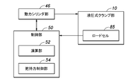
- FIG. 8 is a block diagram showing a control circuit of the hydraulic clamp device according to the second embodiment of the present invention.
- the same parts as those in the first embodiment will be designated by the same reference numerals, and different configurations and operations will be described.
- a load cell 85 as a pressure measuring device is attached to the tip of the power cylinder portion 46.
- the work gripping start point (zero point) is obtained by calculating the stroke of the power cylinder 46 and the pressure of the load cell 85, as in the first embodiment.
- the load cell 85 as the pressure measuring device, the structure can be simplified as compared with the hydraulic pressure measuring unit 72 as in the first embodiment.
- the load cell 85 is attached to the tip of the power cylinder portion 46 in the present embodiment, the present invention is not limited to this, and may be incorporated into the piston rod 47 or the hydraulic clamp portion 10. Other configurations and operations are the same as those in the first embodiment, and therefore the description thereof is omitted.
- the hydraulic clamp device 100 is of a mandrel type, and includes a clamp member 106 including a main body (first member) 102 having a substantially round bar shape and a cylindrical body (second member) 104 forming a wall body having a thin wall structure. Have.
- the main body 102 has a first shaft-shaped portion 108, a flange portion 110, and a second shaft-shaped portion 112 on the same axis line in order in the axial direction.
- the flange portion 110 has a larger outer diameter than the first shaft-shaped portion 108 and the second shaft-shaped portion 112, and extends outward in the radial direction with respect to the first shaft-shaped portion 108 and the second shaft-shaped portion 112.
- a circumferential groove-shaped recess 114 is formed on the outer periphery of the first shaft-shaped portion 108.
- the cylindrical body 104 is fitted on the outer periphery of the first shaft-shaped portion 108, and the inner peripheral surface 104A (inner surface side) corresponding to the recess 114 defines a working liquid chamber 116 having an annular cross-sectional shape.
- O-rings 118 for securing the liquid tightness of the working liquid chamber 116 are attached to both sides of the outer peripheral surface 108A of the first shaft-shaped portion 108 in the axial direction with the working liquid chamber 116 interposed therebetween.
- the cylindrical body 104 defines a clamp surface for clamping a clamped member (workpiece) W2 (see FIG. 11) including a cylindrical portion by an outer peripheral surface (outer surface side) 104B.
- the cylindrical portion 120A of the outer cylindrical body 120 is fitted to the outer periphery (outer peripheral surface 108A) of the first shaft-shaped portion 108.
- the outer cylindrical body 120 includes a flange portion 120B formed on one axial end side of the cylindrical portion 120A, and the flange portion 120B is fixed to the flange portion 110 with a bolt 122.
- the cylindrical portion 120A includes a thin portion that overlaps the outer periphery of the cylindrical body 104.
- the outer tubular body 120 positions the clamped member W2 in the axial direction by abutting the clamped member W2 on the tip of the cylindrical portion 120A.
- a first piston chamber 130 that extends in the axial direction on the central axis is formed in the second shaft-shaped portion 112 of the main body 102.
- a second piston chamber 132 extending in the radial direction is formed in the flange portion 110 of the main body 102.
- the first piston chamber 130 and the second piston chamber 132 communicate with each other inside the main body 102.
- a first piston 134 is provided in the first piston chamber 130 so as to be movable in the extending direction of the first piston chamber 130.
- a second piston 136 is provided in the second piston chamber 132 so as to be movable in the extending direction of the second piston chamber 132.
- One end (right side in FIG. 9) of the first piston chamber 130 communicates with the working liquid chamber 116 through an axial passage 138 formed in the main body 102 and a plurality of radial passages 140. ..
- the passage 138 side of the first piston chamber 130 divided by the first piston 134, the first piston chamber 130 side of the second piston chamber 132 divided by the second piston 136, the passages 138, 140 and the working liquid chamber 116 are One closed space is formed, and this closed space is filled and filled with working oil which is working liquid.
- a bush 142 is screwed to the second shaft-shaped portion 112 of the main body 102, which is the other side of the first piston 134 (left side in FIG. 9).
- a through hole 142A is formed in the bush 142 so as to penetrate the central portion in the axial direction.
- a push rod 144 is engaged with the through hole 142A coaxially with the first piston 134 so as to be movable in the axial direction.
- the push rod 144 moves the first piston 134 forward through the steel ball 146 by moving to the first piston 134 side (moving to the right in FIG. 9).
- the forward movement of the first piston 134 quantitatively pressurizes the working liquid in the working liquid chamber 116 according to the forward movement amount of the first piston 134.
- the first piston 134 moves forward by being pressed by the push rod 144 from the outside.
- the push rod 144 has the enlarged diameter portion 144A at the end portion on the steel ball 146 side, so that the push rod 144 is restricted from moving to the left as viewed in FIG. 9 and is prevented from coming off.
- the flange portion 110 is formed with a screw hole 148 having an outer end opened to the outer peripheral surface of the flange portion 110 and an inner end communicating with the opposite side of the second piston chamber 132 from the first piston chamber 130.
- An operating screw member 150 is screwed into the screw hole 148.
- the operating screw member 150 advances the second piston 136 via the steel ball 152 by screwing (moving upward as viewed in FIG. 9 ).
- the forward movement of the second piston 136 quantitatively pressurizes the hydraulic fluid in the hydraulic fluid chamber 116 according to the forward movement amount of the second piston 136.
- the cylindrical body 104 expands in diameter by elastic deformation, and the outer periphery of the cylindrical body 104.
- the clamped member W2 is clamped (gripped).
- a pressure sensor device (pressure measuring device) 160 is attached to the flange portion 110.
- the pressure sensor device 160 is equivalent to the above-described pressure sensor device 60, and the pressure (hydraulic pressure) of the working liquid in the working liquid chamber 116 is exerted from the pressure propagation passage 154 filled with the working liquid. To measure.
- An external setup device 200 is provided in order to efficiently perform the work gripping start point detection method and the work gripping method.
- the outer setup device 200 presses the main body 202, the chuck device 204 that detachably fixes the hydraulic clamp device 100 to the main body 202, and the push rod 144 to move the first piston 134 of the hydraulic clamp device 100 forward.
- a hydraulic or electric linear actuator 206 a piston movement position detection device 208 for detecting the movement position (stroke) of the first piston 134 from the drive amount of the linear actuator 206, and a sequence for controlling the drive of the linear actuator 206.
- a control device 210 a control device 210.
- a work gripping start point detection device 212 for carrying out the work gripping start point detection method according to the present embodiment is provided along with the external setup device 200.
- the workpiece gripping start point detection device 212 is of an electronic control type including a microcomputer, and inputs a signal (measurement data) indicating the pressure of the working liquid in the working liquid chamber 116 from the pressure sensor device 160 of the hydraulic clamp device 100. Then, a signal (measurement data) indicating the moving position of the first piston 134 is input from the piston moving position detection device 208, and the moving position of the first piston 134 is driven by the sequence control device 210 driving the linear actuator 206 forward.
- the work gripping start point is detected based on the change in the pressure of the working liquid in the working liquid chamber 116 with respect to.
- the pressure of the working liquid in the working liquid chamber 116 can be detected from the measured value by measuring the load acting on the first piston 134 by the load cell 207 attached to the linear actuator 206.
- the work gripping start point referred to here is the movement position of the first piston 134 and the operation of the working liquid chamber 116 at the time when the outer peripheral surface 104B of the cylindrical body 104 starts contacting with the inner peripheral surface of the clamped member W2. It is specified by the pressure of the liquid.
- the work gripping start point detection device 212 detects the work gripping start point on the outer peripheral surface 104B of the cylindrical body 104 based on the pressure change of the working liquid in the working liquid chamber 116 with respect to the moving position of the first piston 134.
- the point is to specify the time when the contact with the inner peripheral surface of the clamp member W2 is started, and to detect the moving position of the first piston 134 and the pressure of the working liquid in the working liquid chamber 116 at that time.
- the detection result of the work gripping start point is displayed on the monitor 214.
- the work gripping start point detection device 212 detects the work gripping start point according to any of the embodiments (A) to (C) or a combination thereof.
- the time point at which the rate of increase in the pressure of the working liquid in the working liquid chamber 116 with respect to the moving position of the first piston 134 changes is the work gripping start point.
- the embodiment (A) corresponds to the above-described third work gripping start point calculation method.
- Equation 1 and (Equation 2) are proportional constants, respectively, and m ⁇ n.
- the proportional constants m and n correspond to the slopes of the straight lines based on the straight line data of the sections a and b.
- the solution of the simultaneous equations according to (Equation 1) and (Equation 2) is the intersection of two straight lines.
- the embodiment (B) corresponds to the first and second work gripping start point calculation methods.
- the estimation can be performed by taking the tolerance into consideration.
- the outer diameter of the outer peripheral surface 104B becomes the lower limit of the tolerance of the clamped member W2 from the initial position. It is a section up to the position where it expands to the corresponding outer diameter.
- the movement section of the first piston 134 in which the outer peripheral surface 104B abuts the inner peripheral surface of the clamped member W2 is located outside the outer peripheral surface 104B from the position where it expands to the outer diameter corresponding to the lower limit of the tolerance of the clamped member W2.
- the area is the area up to the maximum allowable diameter.
- the moving position of the first piston 134 and the operation of the working liquid chamber 116 in a state in which the clamped member W2 is not attached to the hydraulic clamp device 100 and a state in which the clamped member W2 is attached thereto Since the section showing the relationship with the liquid pressure is large, it can be expected that the detection accuracy of the work gripping start point is improved as compared with the embodiment (B).
- the work gripping method according to the present embodiment is carried out in the following manner after the work gripping start point detection work described above.
- the linear actuator 206 is driven backward to return the first piston 134 to the initial position, and the hydraulic type With the member W2 to be clamped attached to the clamp device 100, the pressure of the working liquid in the working liquid chamber 116 at the work gripping start point is changed by the screwing of the working screw member 150 by the tool 220, and the working liquid chamber at the work gripping start point. The pressure is increased until the value obtained by adding the pressure necessary to obtain the required work gripping force to the pressure of the working liquid 116 is monitored and displayed.
- the hydraulic clamp device 100 which has completed the external setup, is attached to the chuck device 232 of the machine tool 230 as shown in FIG. 11 while holding the clamped member W2.
- the hydraulic clamp device 300 is of a chuck type, and includes a substantially circular rod-shaped cylindrical main body (first member) 302 and a cylindrical body (second member) 310 forming a thin-walled wall body. It has a member 308.
- the main body 302 has a first tubular portion 304 and a second tubular portion 306 on the same axis in the axial direction.
- the second tubular portion 306 has a larger diameter than the first tubular portion 304 and forms a flange portion that is expanded in the radial direction.
- the cylindrical body 310 is fitted on the inner circumference of the main body 302.
- the cylindrical body 310 includes an inner peripheral surface 310A that clamps the clamped member W3 having a round bar shape and an outer peripheral surface (second peripheral surface) 310B that overlaps the inner peripheral surface (first peripheral surface) 302A of the main body 302. ing.
- a peripheral groove-shaped recess 312 is formed on the outer peripheral surface 310B of the cylindrical body 310.
- the main body 302 and the cylindrical body 310 define a working liquid chamber 314 having a circular cross section (cross section orthogonal to the central axis) extending along the entire circumference of the inner peripheral surface 302A of the main body 302 by the recess 312. ing.
- the cylindrical body 310 forming the wall body defines the working liquid chamber 314 on the inner surface side and the clamp surface (inner peripheral surface 310A) on the outer surface side.
- O-rings 316 for securing the liquid tightness of the working liquid chamber 314 are attached to both sides of the inner circumferential surface 302A of the main body 302 with the working liquid chamber 314 sandwiched in the axial direction.
- a piston chamber 318 extending in the axial direction is formed in the main body 302.
- a piston 320 is fitted in the piston chamber 318 so as to be movable in the axial direction.
- One end of the piston chamber 318 communicates with the working liquid chamber 314 by a radial passage 322 formed in the second tubular portion 306.
- the chamber space on the side of the passage 322 of the piston chamber 318, which is divided by the piston 320, the passage 322 and the working liquid chamber 314 form one sealed space, in which working oil such as grease is sealed.
- the main body 302 is formed with a screw hole 324 which extends in the axial direction and communicates with the other end of the piston chamber 318 and which is open to the end surface 304A of the first tubular portion 304.
- An operating screw member 326 having a hexagonal hole is screwed into the screw hole 324.
- a steel ball 328 is arranged between the actuating screw member 326 and the piston 320. The operating screw member 326 is screwed to screw the screw hole 324 to the piston chamber 318 side, and the piston 320 is moved forward through the steel ball 328 by the screwing.
- the pressurizing structure is configured, and the piston 320 moves to the passage 322 side (left side in FIG. 12) in the piston chamber 318 by screwing the operation screw member 326, so that the operation oil in the operation liquid chamber 314 is released.
- the cylindrical body 310 is pressed, and the cylindrical body 310 is deformed radially inward by elastic deformation in the radial direction.
- the clamped member W3 is clamped on the inner peripheral surface 310A of the cylindrical body 310 due to the contraction deformation of the cylindrical body 310. More specifically, the clamped member W3 is fixed (clamped) to the hydraulic clamp device 300 by the inner peripheral surface 310A of the cylindrical body 310 coming into close contact with the outer peripheral surface due to the contraction deformation of the cylindrical body 310. ..
- the pressure sensor device 60 is attached to the second tubular portion 306.
- the pressure sensor device 60 is equivalent to that of the first embodiment, and the pressure (hydraulic pressure) of the working liquid in the working liquid chamber 314 is exerted from the pressure propagation passage 330 formed in the main body 302, and the liquid pressure is changed. taking measurement.
- the hydraulic pressure of the working liquid chamber 314 measured by the pressure sensor device 60 is displayed on the display unit 94 of the wireless reader 90 by wireless communication, as in the first embodiment.
- the mandrel type hydraulic clamp unit 10 and the hydraulic type clamp unit 10 described above are measured based on the measurement of the hydraulic pressure of the working liquid chamber 314 and the movement amount of the piston 320 by the pressure sensor device 60.
- the work gripping start point can be detected and the work can be gripped by the same method as the work gripping start point detection method and the work gripping method in the clamp device 100.
- the hydraulic clamp device 400 is of a chuck type, and includes a substantially rod-shaped cylindrical main body (first member) 402 and a thin-walled cylindrical body (second member) 412 as a clamp. It has a member 420.
- the main body 402 has a first shaft-shaped portion 404, a flange portion 406, and a second shaft-shaped portion 408 in the axial direction in order on the same axis.
- the flange portion 406 has an outer diameter larger than those of the first shaft-shaped portion 404 and the second shaft-shaped portion 408, and extends outward in the radial direction with respect to the first shaft-shaped portion 404 and the second shaft-shaped portion 408. Has been formed.
- a bottomed hole 410 having a circular cross-sectional shape that opens to the right end surface of the first shaft-shaped portion 404 in FIG. 13.
- the cylindrical body 412 is fitted into the bottomed hole 410, and defines a working liquid chamber 314 having an annular cross-section with the main body 402 by a circumferential groove-shaped recess 414 formed on the outer peripheral surface.
- the main body 402 and the cylindrical body 412 are joined to each other on both sides in the axial direction of the working liquid chamber 314 by brazing (not shown) continuous in the circumferential direction of the main body 402 and the cylindrical body 412, respectively. This ensures the liquid tightness of the working liquid chamber 314.
- the cylindrical body 412 defines a clamp surface for clamping the clamped member (workpiece) W3 by the inner peripheral surface (outer surface side) 412A.
- the cylindrical body 412 forming the wall defines the working liquid chamber 314 on the inner surface side and the clamping surface (inner peripheral surface 412A) on the outer surface side.
- the main body 402 includes the first piston chamber 130, the first piston 134, the push rod 144, etc., and the push rod 144 is pushed from the outside to increase the hydraulic pressure of the working liquid chamber 314.
- a second pressurizing mechanism that includes a piston chamber 318, a piston 320, an operating screw member 326, and the like, and increases the hydraulic pressure of the operating liquid chamber 314 by screwing the operating screw member 326, as in the fourth embodiment. And a pressure mechanism.
- the pressure sensor device 60 for measuring the pressure (fluid pressure) of the working liquid in the working liquid chamber 314 is attached to the flange portion 406, as in the first and fourth embodiments.
- the mandrel type hydraulic clamp described above is measured based on the measurement of the hydraulic pressure of the working liquid chamber 314 and the movement amount of the first piston 134 and the piston 320 by the pressure sensor device 60.
- the work gripping start point can be detected and the work gripping can be performed by the same method as the work gripping start point detection method and the work gripping method in the unit 10 and the hydraulic clamp device 100.
- the present invention can be applied to a device having a tapered collet.
- a tapered collet is provided in place of the cylindrical body 24, a cylindrical main body having an outer peripheral surface formed in a tapered shape is provided in the tapered collet, and the outer peripheral surface of the tapered collet is clamped to a member to be clamped. It is inserted into the inner peripheral surface of W1 so that the cylindrical main body is pulled from the tapered collet. As a result, the stroke (axial position) of the cylindrical body changes, and the pressure applied to the clamped members W1W2 changes.
- Hydraulic clamp 12 Main body (first member) 16: 1st axial part 16A: Outer peripheral surface (1st peripheral surface) 16B: end surface 18: flange portion 20: second shaft portion 22: rod portion 24: cylindrical body (second member) 24A: outer peripheral surface 24B: inner peripheral surface (second peripheral surface) 28: recess 30: working liquid chamber 32: O-ring 34: piston chamber 36: piston 38: passage 40: passage 42: bush 42A: through hole 44: push rod 46: power cylinder portion (driving device) 47: Piston rod 48: Steel ball 50: Control part 52: Calculation part (calculation device) 54: Grip force control unit (grip force control device) 60: Pressure sensor device 62: Flange part 64: Male screw part 65: Recessed groove 66: Hexagonal part 67: Rubber packing 68: Housing 69: Oil 70: Cap part 72: Liquid pressure measuring part (pressure measuring device) 74: Pressure introducing passage 76: Wireless communication portion 78: Power receiving portion 80: Screw hole 82
Landscapes
- Engineering & Computer Science (AREA)
- Mechanical Engineering (AREA)
- Gripping On Spindles (AREA)
- Jigs For Machine Tools (AREA)
Abstract
La présente invention vise à fournir un dispositif de serrage hydraulique qui peut trouver un point de départ de préhension de pièce à travailler sur des pièces à travailler ayant chacune des variations de dimensions dans les limites d'une tolérance. À cet effet, l'invention concerne un dispositif de serrage hydraulique qui, dans une partie où un corps principal (12), qui est un premier élément, et le corps cylindrique (24), qui est un second élément, se chevauchent, serre un élément serré (W1) au moyen d'une déformation élastique d'un corps cylindrique (24) provoquée par la pression d'un fluide de travail scellé à l'intérieur d'une chambre de fluide de travail (30), la chambre de fluide de travail (30) étant définie par une section évidée (28) disposée dans au moins l'une d'une surface circonférentielle externe (16A) qui est une première surface circonférentielle et d'une surface circonférentielle interne (24B) qui est une seconde surface circonférentielle. Le dispositif de serrage hydraulique comprend un dispositif informatique qui calcule un point de départ de préhension de pièce à travailler où le serrage de l'élément serré (W1) par le corps cylindrique (24) débute.
Priority Applications (1)
| Application Number | Priority Date | Filing Date | Title |
|---|---|---|---|
| JP2020546192A JP6887063B2 (ja) | 2019-02-21 | 2020-02-20 | 液圧式クランプ装置、液圧式クランプ装置におけるワーク把持開始点検出方法、ワーク把持開始点検出装置及びワーク把持方法 |
Applications Claiming Priority (2)
| Application Number | Priority Date | Filing Date | Title |
|---|---|---|---|
| JP2019-029630 | 2019-02-21 | ||
| JP2019029630A JP6665329B1 (ja) | 2019-02-21 | 2019-02-21 | 液圧式クランプ装置 |
Publications (1)
| Publication Number | Publication Date |
|---|---|
| WO2020171172A1 true WO2020171172A1 (fr) | 2020-08-27 |
Family
ID=70000305
Family Applications (1)
| Application Number | Title | Priority Date | Filing Date |
|---|---|---|---|
| PCT/JP2020/006823 Ceased WO2020171172A1 (fr) | 2019-02-21 | 2020-02-20 | Dispositif de serrage hydraulique, procédé de détection de point de départ de préhension de pièce à travailler d'un dispositif de serrage hydraulique, dispositif de détection de point de départ de préhension de pièce à travailler, et procédé de préhension de pièce à travailler |
Country Status (2)
| Country | Link |
|---|---|
| JP (2) | JP6665329B1 (fr) |
| WO (1) | WO2020171172A1 (fr) |
Cited By (2)
| Publication number | Priority date | Publication date | Assignee | Title |
|---|---|---|---|---|
| CN115070475A (zh) * | 2022-08-03 | 2022-09-20 | 广州德马威工业装备制造有限公司 | 一种精密液胀夹具 |
| CN117300671A (zh) * | 2023-11-15 | 2023-12-29 | 中国航发沈阳黎明航空发动机有限责任公司 | 一种前轴颈喷丸变形修复的加工方法 |
Citations (5)
| Publication number | Priority date | Publication date | Assignee | Title |
|---|---|---|---|---|
| JPS6340493B2 (fr) * | 1981-09-21 | 1988-08-11 | Tokyo Denpa Kk | |
| DE3800696A1 (de) * | 1988-01-13 | 1989-07-27 | Schunk Fritz Gmbh | Verfahren zur herstellung von dehnspannwerkzeugen mit dehnelementen aus faserverbundwerkstoffen |
| JPH0219440U (fr) * | 1988-07-20 | 1990-02-08 | ||
| JP2005324277A (ja) * | 2004-05-13 | 2005-11-24 | Toyota Motor Corp | クランプ装置およびそのクランプ確認方法 |
| JP2016159418A (ja) * | 2015-03-05 | 2016-09-05 | Smc株式会社 | クランプ装置 |
Family Cites Families (7)
| Publication number | Priority date | Publication date | Assignee | Title |
|---|---|---|---|---|
| US4673173A (en) * | 1986-01-31 | 1987-06-16 | Kabushiki Kaisha Nippei Toyama | Workpiece clamping device |
| JP2003194019A (ja) * | 2001-12-28 | 2003-07-09 | Kuroda Precision Ind Ltd | クランプ装置 |
| JP3768917B2 (ja) * | 2002-05-14 | 2006-04-19 | 独立行政法人科学技術振興機構 | 摩擦力および粘性減衰係数測定法 |
| JP4559867B2 (ja) * | 2005-01-21 | 2010-10-13 | 日立建機株式会社 | 把持力制御装置および作業機械 |
| JP2008142718A (ja) * | 2006-12-06 | 2008-06-26 | Toko Seisakusho:Kk | ストレッチベンダー機 |
| JP4638464B2 (ja) * | 2007-03-29 | 2011-02-23 | 三菱重工業株式会社 | 工作機械の主軸装置 |
| JP6340493B1 (ja) * | 2017-08-31 | 2018-06-06 | 黒田精工株式会社 | 液圧式クランプ装置及び液圧式クランプ装置の寿命判定方法 |
-
2019
- 2019-02-21 JP JP2019029630A patent/JP6665329B1/ja active Active
-
2020
- 2020-02-20 JP JP2020546192A patent/JP6887063B2/ja active Active
- 2020-02-20 WO PCT/JP2020/006823 patent/WO2020171172A1/fr not_active Ceased
Patent Citations (5)
| Publication number | Priority date | Publication date | Assignee | Title |
|---|---|---|---|---|
| JPS6340493B2 (fr) * | 1981-09-21 | 1988-08-11 | Tokyo Denpa Kk | |
| DE3800696A1 (de) * | 1988-01-13 | 1989-07-27 | Schunk Fritz Gmbh | Verfahren zur herstellung von dehnspannwerkzeugen mit dehnelementen aus faserverbundwerkstoffen |
| JPH0219440U (fr) * | 1988-07-20 | 1990-02-08 | ||
| JP2005324277A (ja) * | 2004-05-13 | 2005-11-24 | Toyota Motor Corp | クランプ装置およびそのクランプ確認方法 |
| JP2016159418A (ja) * | 2015-03-05 | 2016-09-05 | Smc株式会社 | クランプ装置 |
Cited By (2)
| Publication number | Priority date | Publication date | Assignee | Title |
|---|---|---|---|---|
| CN115070475A (zh) * | 2022-08-03 | 2022-09-20 | 广州德马威工业装备制造有限公司 | 一种精密液胀夹具 |
| CN117300671A (zh) * | 2023-11-15 | 2023-12-29 | 中国航发沈阳黎明航空发动机有限责任公司 | 一种前轴颈喷丸变形修复的加工方法 |
Also Published As
| Publication number | Publication date |
|---|---|
| JP6665329B1 (ja) | 2020-03-13 |
| JP6887063B2 (ja) | 2021-06-16 |
| JPWO2020171172A1 (ja) | 2021-09-13 |
| JP2020131382A (ja) | 2020-08-31 |
Similar Documents
| Publication | Publication Date | Title |
|---|---|---|
| CN104275613B (zh) | 用于机床的夹紧装置和夹紧方法 | |
| KR102255129B1 (ko) | 파스너 | |
| US9823148B2 (en) | Force-measuring device | |
| JP6887063B2 (ja) | 液圧式クランプ装置、液圧式クランプ装置におけるワーク把持開始点検出方法、ワーク把持開始点検出装置及びワーク把持方法 | |
| US6414259B2 (en) | Inter-welding electrode moving amount detecting method and apparatus thereof | |
| US10821564B2 (en) | Cylinder device, press machine, workpiece clamping apparatus, cylinder device actuating method, method for clamping workpiece, and method for pressing workpiece | |
| US6418795B2 (en) | Method of measuring shear friction factor through backward extrusion process | |
| CN102083564B (zh) | 液压成形加工装置及液压成形加工方法 | |
| EP1909987B1 (fr) | Système et procédé pour sertir un embout sur un conduit pour fluides | |
| JP6825172B1 (ja) | 液圧式クランプ装置、液圧式クランプ装置におけるワーク把持開始点検出方法、ワーク把持開始点検出装置及びワーク把持方法 | |
| US20170355048A1 (en) | Steady rest | |
| US10941790B2 (en) | Cylinder device, press machine, workpiece clamping apparatus, cylinder device actuating method, method for clamping workpiece, and method for pressing workpiece | |
| JP2004505781A (ja) | 加工片端部範囲を変形する装置 | |
| WO2016041052A1 (fr) | Machine à détection indirecte de la position de l'élément de fixation soudable | |
| US20200078844A1 (en) | Pressing tool with a drive controlled based on recorded pressing data | |
| US10982690B2 (en) | Cylinder device, press machine, workpiece clamping apparatus, cylinder device actuating method, method for clamping workpiece, and method for pressing workpiece | |
| CN118848608B (zh) | 一种多级自适应随形压紧方法 | |
| JP2016028227A (ja) | 力覚センサを利用して対象物を検査する検査システム | |
| CN112423932B (zh) | 具备夹紧对象物的动作检测功能的夹紧系统 | |
| EP4520454A1 (fr) | Dispositif d'assemblage avec dispositif de serrage et procédé d'assemblage | |
| JPH1047312A (ja) | 油圧シリンダーの内部漏れ検出方法 | |
| EP3653334B1 (fr) | Dispositif de préhension | |
| KR20180093812A (ko) | 성형 공구 상의 성형 치형부 구조체의 기능 상태를 모니터링하기 위한 방법 및 장치 | |
| JP2007069275A (ja) | タッチセンサ | |
| TW200842316A (en) | Method and structure for measuring a workpiece hole |
Legal Events
| Date | Code | Title | Description |
|---|---|---|---|
| ENP | Entry into the national phase |
Ref document number: 2020546192 Country of ref document: JP Kind code of ref document: A |
|
| 121 | Ep: the epo has been informed by wipo that ep was designated in this application |
Ref document number: 20759224 Country of ref document: EP Kind code of ref document: A1 |
|
| NENP | Non-entry into the national phase |
Ref country code: DE |
|
| 122 | Ep: pct application non-entry in european phase |
Ref document number: 20759224 Country of ref document: EP Kind code of ref document: A1 |