WO2020174533A1 - タービンハウジングおよびターボチャージャ - Google Patents
タービンハウジングおよびターボチャージャ Download PDFInfo
- Publication number
- WO2020174533A1 WO2020174533A1 PCT/JP2019/007065 JP2019007065W WO2020174533A1 WO 2020174533 A1 WO2020174533 A1 WO 2020174533A1 JP 2019007065 W JP2019007065 W JP 2019007065W WO 2020174533 A1 WO2020174533 A1 WO 2020174533A1
- Authority
- WO
- WIPO (PCT)
- Prior art keywords
- inlet
- scroll
- exhaust gas
- tip portion
- side tip
- Prior art date
- Legal status (The legal status is an assumption and is not a legal conclusion. Google has not performed a legal analysis and makes no representation as to the accuracy of the status listed.)
- Ceased
Links
Images




Classifications
-
- F—MECHANICAL ENGINEERING; LIGHTING; HEATING; WEAPONS; BLASTING
- F02—COMBUSTION ENGINES; HOT-GAS OR COMBUSTION-PRODUCT ENGINE PLANTS
- F02B—INTERNAL-COMBUSTION PISTON ENGINES; COMBUSTION ENGINES IN GENERAL
- F02B37/00—Engines characterised by provision of pumps driven at least for part of the time by exhaust
- F02B37/12—Control of the pumps
- F02B37/24—Control of the pumps by using pumps or turbines with adjustable guide vanes
-
- F—MECHANICAL ENGINEERING; LIGHTING; HEATING; WEAPONS; BLASTING
- F01—MACHINES OR ENGINES IN GENERAL; ENGINE PLANTS IN GENERAL; STEAM ENGINES
- F01D—NON-POSITIVE DISPLACEMENT MACHINES OR ENGINES, e.g. STEAM TURBINES
- F01D9/00—Stators
- F01D9/02—Nozzles; Nozzle boxes; Stator blades; Guide conduits, e.g. individual nozzles
- F01D9/026—Scrolls for radial machines or engines
-
- F—MECHANICAL ENGINEERING; LIGHTING; HEATING; WEAPONS; BLASTING
- F01—MACHINES OR ENGINES IN GENERAL; ENGINE PLANTS IN GENERAL; STEAM ENGINES
- F01D—NON-POSITIVE DISPLACEMENT MACHINES OR ENGINES, e.g. STEAM TURBINES
- F01D11/00—Preventing or minimising internal leakage of working-fluid, e.g. between stages
- F01D11/003—Preventing or minimising internal leakage of working-fluid, e.g. between stages by packing rings; Mechanical seals
-
- F—MECHANICAL ENGINEERING; LIGHTING; HEATING; WEAPONS; BLASTING
- F01—MACHINES OR ENGINES IN GENERAL; ENGINE PLANTS IN GENERAL; STEAM ENGINES
- F01D—NON-POSITIVE DISPLACEMENT MACHINES OR ENGINES, e.g. STEAM TURBINES
- F01D17/00—Regulating or controlling by varying flow
- F01D17/10—Final actuators
- F01D17/12—Final actuators arranged in stator parts
- F01D17/14—Final actuators arranged in stator parts varying effective cross-sectional area of nozzles or guide conduits
- F01D17/16—Final actuators arranged in stator parts varying effective cross-sectional area of nozzles or guide conduits by means of nozzle vanes
- F01D17/165—Final actuators arranged in stator parts varying effective cross-sectional area of nozzles or guide conduits by means of nozzle vanes for radial flow, i.e. the vanes turning around axes which are essentially parallel to the rotor centre line
-
- F—MECHANICAL ENGINEERING; LIGHTING; HEATING; WEAPONS; BLASTING
- F01—MACHINES OR ENGINES IN GENERAL; ENGINE PLANTS IN GENERAL; STEAM ENGINES
- F01D—NON-POSITIVE DISPLACEMENT MACHINES OR ENGINES, e.g. STEAM TURBINES
- F01D25/00—Component parts, details, or accessories, not provided for in, or of interest apart from, other groups
- F01D25/24—Casings; Casing parts, e.g. diaphragms, casing fastenings
- F01D25/26—Double casings; Measures against temperature strain in casings
-
- F—MECHANICAL ENGINEERING; LIGHTING; HEATING; WEAPONS; BLASTING
- F02—COMBUSTION ENGINES; HOT-GAS OR COMBUSTION-PRODUCT ENGINE PLANTS
- F02C—GAS-TURBINE PLANTS; AIR INTAKES FOR JET-PROPULSION PLANTS; CONTROLLING FUEL SUPPLY IN AIR-BREATHING JET-PROPULSION PLANTS
- F02C6/00—Plural gas-turbine plants; Combinations of gas-turbine plants with other apparatus; Adaptations of gas-turbine plants for special use
- F02C6/04—Gas-turbine plants providing heated or pressurised working fluid for other apparatus, e.g. without mechanical power output
- F02C6/10—Gas-turbine plants providing heated or pressurised working fluid for other apparatus, e.g. without mechanical power output supplying working fluid to a user, e.g. a chemical process, which returns working fluid to a turbine of the plant
- F02C6/12—Turbochargers, i.e. plants for augmenting mechanical power output of internal-combustion piston engines by increase of charge pressure
-
- F—MECHANICAL ENGINEERING; LIGHTING; HEATING; WEAPONS; BLASTING
- F05—INDEXING SCHEMES RELATING TO ENGINES OR PUMPS IN VARIOUS SUBCLASSES OF CLASSES F01-F04
- F05D—INDEXING SCHEME FOR ASPECTS RELATING TO NON-POSITIVE-DISPLACEMENT MACHINES OR ENGINES, GAS-TURBINES OR JET-PROPULSION PLANTS
- F05D2220/00—Application
- F05D2220/40—Application in turbochargers
-
- F—MECHANICAL ENGINEERING; LIGHTING; HEATING; WEAPONS; BLASTING
- F05—INDEXING SCHEMES RELATING TO ENGINES OR PUMPS IN VARIOUS SUBCLASSES OF CLASSES F01-F04
- F05D—INDEXING SCHEME FOR ASPECTS RELATING TO NON-POSITIVE-DISPLACEMENT MACHINES OR ENGINES, GAS-TURBINES OR JET-PROPULSION PLANTS
- F05D2230/00—Manufacture
- F05D2230/50—Building or constructing in particular ways
- F05D2230/54—Building or constructing in particular ways by sheet metal manufacturing
-
- F—MECHANICAL ENGINEERING; LIGHTING; HEATING; WEAPONS; BLASTING
- F05—INDEXING SCHEMES RELATING TO ENGINES OR PUMPS IN VARIOUS SUBCLASSES OF CLASSES F01-F04
- F05D—INDEXING SCHEME FOR ASPECTS RELATING TO NON-POSITIVE-DISPLACEMENT MACHINES OR ENGINES, GAS-TURBINES OR JET-PROPULSION PLANTS
- F05D2240/00—Components
- F05D2240/10—Stators
- F05D2240/14—Casings or housings protecting or supporting assemblies within
-
- F—MECHANICAL ENGINEERING; LIGHTING; HEATING; WEAPONS; BLASTING
- F05—INDEXING SCHEMES RELATING TO ENGINES OR PUMPS IN VARIOUS SUBCLASSES OF CLASSES F01-F04
- F05D—INDEXING SCHEME FOR ASPECTS RELATING TO NON-POSITIVE-DISPLACEMENT MACHINES OR ENGINES, GAS-TURBINES OR JET-PROPULSION PLANTS
- F05D2240/00—Components
- F05D2240/55—Seals
-
- Y—GENERAL TAGGING OF NEW TECHNOLOGICAL DEVELOPMENTS; GENERAL TAGGING OF CROSS-SECTIONAL TECHNOLOGIES SPANNING OVER SEVERAL SECTIONS OF THE IPC; TECHNICAL SUBJECTS COVERED BY FORMER USPC CROSS-REFERENCE ART COLLECTIONS [XRACs] AND DIGESTS
- Y02—TECHNOLOGIES OR APPLICATIONS FOR MITIGATION OR ADAPTATION AGAINST CLIMATE CHANGE
- Y02T—CLIMATE CHANGE MITIGATION TECHNOLOGIES RELATED TO TRANSPORTATION
- Y02T10/00—Road transport of goods or passengers
- Y02T10/10—Internal combustion engine [ICE] based vehicles
- Y02T10/12—Improving ICE efficiencies
Definitions
- the present disclosure relates to a turbine housing and a turbocharger including the turbine housing.
- the turbine wheel is rotated using the energy of the exhaust gas introduced from the engine, and the compressor wheel provided coaxially with the turbine wheel is rotated to supply compressed air to the intake manifold to reduce engine output.
- Turbochargers designed to improve are known.
- the turbine wheel of the turbocharger is housed in the turbine housing. Since the turbine housing is generally manufactured by casting, it has a large wall thickness and a large heat capacity in consideration of the flow of molten metal in the mold. In such a cast turbine housing, the thermal energy of the exhaust gas flowing through the turbine housing is absorbed by the turbine housing when the engine is started, so the temperature of the exhaust gas decreases. If the temperature of the exhaust gas decreases, there is a risk of hindering the temperature rise of the exhaust purification catalyst located downstream of the turbine. For this reason, in recent years, in order to reduce the heat capacity and reduce the weight of the turbine housing, there has been proposed a turbine housing made of a sheet metal manufactured by sheet metal working from a thin and flat metal plate.
- Patent Document 1 discloses a turbine housing in which a heat shield space is formed between an inner peripheral surface of a housing portion forming a spiral space and an outer peripheral surface of a housing-side inner casing forming a spiral exhaust gas passage. ing.
- Patent Document 2 a thin funnel-shaped inlet-side inner casing (sleeve) that is inserted into an inlet connection portion adjacent to a housing portion that forms a spiral space, and a housing-side inner casing (sleeve) that is inserted into the housing portion.
- the housing-side inner casing inner casing is arranged only in the housing portion as in the invention described in Patent Document 1, the thermal energy of the exhaust gas before being introduced into the turbine wheel is absorbed by the inlet connection portion adjacent to the housing.
- the temperature of the exhaust gas may decrease.
- the temperature of the exhaust gas introduced into the turbine wheel decreases, which may reduce the performance of the turbine wheel.
- the heat input from the exhaust gas is large at the inlet connection portion and the temperature tends to be high, it may be difficult to secure the high temperature strength of the turbine housing.
- Patent Document 2 discloses disposing the inner casing (housing-side inner casing, inlet-side inner casing) separately in each of the housing portion and the inlet connection portion, but the housing-side inner casing. There is no specific disclosure of connection between the inner casing and the inlet side inner casing. If there is a gap between the inner casing on the housing side and the inner casing on the inlet side, the exhaust gas leaks to the outside of the inner casing through the gap (internal leak), and heat from the exhaust gas to the housing part and inlet connection part Since the input becomes large, it may be difficult to secure the high temperature strength of the turbine housing.
- an object of at least one embodiment of the present invention is to provide a turbine housing that can reduce internal leakage and improve high temperature strength.
- a turbine housing for housing a turbine wheel, comprising: A scroll portion configured to define a spiral space therein, An exhaust gas introducing port for introducing exhaust gas is formed, and a cylindrical exhaust gas introducing portion configured to internally define a communication passage connecting the exhaust gas introducing port and the spiral space, It is arranged in the spiral space to form a first heat insulating space between itself and the inner surface of the scroll portion, and is configured to internally define a spiral flow path through which the exhaust gas flowing from the exhaust gas introduction port flows.
- An inner scroll member made of sheet metal An inlet member made of a sheet metal, which is separate from the inner scroll member, is disposed in the communication passage, forms a second heat insulating space with the inner surface of the exhaust gas introducing portion, and introduces the exhaust gas.
- An inlet member made of a sheet metal configured to internally define a communication channel that connects the mouth and the spiral channel, The upstream end of the inner scroll member and the downstream end of the inlet member overlap each other along the axial direction of the exhaust gas introducing portion.
- the turbine housing is arranged in the scroll portion, the exhaust gas introducing portion, and the spiral space of the scroll portion, and forms a first heat insulating space between the inner surface of the scroll portion and the sheet metal.
- a sheet metal inlet member that is disposed in the communication passage of the exhaust gas introduction portion and forms a second heat insulating space between the inner scroll member and the inner surface of the exhaust gas introduction portion. That is, the turbine housing is configured such that the inner housing (the inner scroll member made of sheet metal and the inlet is provided inside the outer housing (the scroll portion and the exhaust gas introducing portion) via the heat insulating space (the first heat insulating space and the second heat insulating space). It has a double structure in which members are arranged.
- exhaust gas introduced into the turbine housing is defined inside the inner housing, that is, inside the inlet member made of sheet metal and the inside scroll member made of sheet metal. It is designed to flow through a spiral flow path. Since the sheet metal inlet member and the sheet metal inner scroll member each have a small heat capacity, when the exhaust gas introduced into the turbine housing flows through the communication flow path and the spiral flow path, the thermal energy of the exhaust gas to the outside It is possible to suppress heat dissipation, and it is possible to prevent the temperature of the exhaust gas flowing in the turbine housing from decreasing.
- the upstream end of the inner scroll member and the downstream end of the inlet member overlap each other along the axial direction of the exhaust gas introducing portion. Therefore, the gap that can be formed in the overlapping portion between the upstream end of the inner scroll member and the downstream end of the inlet member is narrower than the other portions and has a large flow path resistance, so that exhaust gas is difficult to pass through. It is structured. Therefore, according to the above configuration, the exhaust gas flowing inside the inner housing is prevented from flowing out of the inner housing, passing between the upstream end portion of the inner scroll member and the downstream end portion of the inlet member. can do. That is, it is possible to reduce the internal leak of the exhaust gas flowing in the turbine housing. Further, the high temperature strength of the turbine housing can be improved by reducing the amount of exhaust gas flowing out of the inner housing and reducing the thermal energy of the exhaust gas absorbed in the outer housing (scroll portion or exhaust gas introducing portion).
- the upstream end of the inner scroll member extends along a direction intersecting the axial direction of the exhaust gas introducing portion.
- a scroll-side crossing portion that exists, and a scroll-side tip end portion that extends toward the upstream side from the tip end of the scroll-side crossing portion, and the downstream end portion of the inlet member is a shaft of the exhaust gas introducing portion.
- the tip of the inlet-side tip is In the radial direction of the exhaust gas introducing portion, the scroll side crossing portion in the radial direction of the exhaust gas introducing portion is configured to be located between the distal end and the base end, and the scroll side distal end portion has a distal end in the radial direction. It is configured to be located between the tip end and the base end of the inlet side intersecting portion, and the scroll side tip portion and the inlet side tip portion are overlapped along the axial direction of the exhaust gas introducing portion. There is.
- the upstream end portion (the scroll side tip portion and the scroll side intersection portion) of the inner scroll member and the downstream end portion (the inlet side tip portion and the inlet side intersection portion) of the inlet member are formed.
- the gap that can be formed between the exhaust gas introducing portion extends along the axial direction of the exhaust gas introducing portion, and each of the gap inlet and the gap outlet opens toward the direction intersecting the axial direction of the exhaust gas introducing portion. There is. Since such a gap changes so that the exhaust gas flow direction bends a plurality of times, the exhaust gas has a structure that does not easily pass through. Therefore, according to the above configuration, it is possible to suppress the exhaust gas flowing inside the inner housing from passing through the gap and flowing out of the inner housing.
- the inlet member has a tip of the inlet-side tip portion abutting on the scroll-side intersecting portion of the inner scroll member. Configured to.
- the exhaust gas flowing inside the inner housing causes the exhaust gas flowing inside the inner housing to reach the upstream end portion of the inner scroll member and the downstream side of the inlet member. It can be prevented from flowing out of the inner housing through a gap formed between the end portion and the inner housing.
- the turbine housing according to (2) or (3) is located radially outside the exhaust gas introducing portion rather than the scroll-side tip portion and the inlet-side tip portion, respectively.
- Each of the scroll-side tip portion and the inlet-side tip portion, which is located, is an attachment plate member configured to overlap along the axial direction of the exhaust gas introduction portion, and is supported by the inner scroll member.
- An additional plate member configured as described above is further provided.
- the attachment plate member is supported by the inner scroll member, and at the outer side in the radial direction of the exhaust gas introducing portion with respect to the scroll side tip portion and the inlet side tip portion, the scroll side tip end. Part and the inlet-side tip end part respectively overlap along the axial direction of the exhaust gas introduction part.
- Such an attachment plate member can extend the above-mentioned gap along the axial direction of the exhaust gas introducing portion on the downstream side of the gap outlet. Since the number of times that the flow direction of the exhaust gas changes so as to bend in the gap increases and the total length of the gap becomes longer, the exhaust gas is more difficult to pass through. Therefore, according to the above configuration, it is possible to suppress the exhaust gas flowing inside the inner housing from passing through the gap and flowing out of the inner housing.
- the inner scroll member has a wall surface of the scroll-side tip portion that is the inlet-side tip portion of the inlet member. It is configured to abut on the wall surface of the exhaust gas along the axial direction of the exhaust gas introducing portion.
- the wall surface of the scroll-side tip portion abuts the wall surface of the inlet-side tip portion along the axial direction of the exhaust gas introducing portion, so that the upstream end portion of the inner scroll member and the inlet member A gap is not formed between the downstream side end portion of the.
- the contact area between the inner scroll member and the inlet member can be increased compared to the case where the tip of the inlet-side tip portion abuts on the scroll-side intersecting portion. It is possible to more reliably prevent the exhaust gas flowing in through the gap from flowing out of the inner housing.
- the turbine housing according to any one of (2) to (4) is arranged in contact with each of the scroll-side tip portion and the inlet-side tip portion, and A gap filling member configured to be able to close a gap provided between the scroll-side tip portion and the inlet-side tip portion is further provided.
- the gap filling member is arranged in contact with each of the scroll-side tip portion and the inlet-side tip portion, and is provided between the scroll-side tip portion and the inlet-side tip portion. Since the gap can be closed, the exhaust gas flowing inside the inner housing can be prevented from passing through the gap and flowing out of the inner housing.
- the turbine housing according to any one of (2) to (4) is arranged in contact with each of the scroll side intersection and the inlet side intersection, and It further comprises a metallic seal member configured to be capable of expanding and contracting along the axial direction of the exhaust gas introducing portion.
- the metal seal member is arranged in contact with each of the scroll-side intersection and the inlet-side intersection, and is expandable/contractible along the axial direction of the exhaust gas introducing portion.
- the metal seal member extends along the axial direction of the exhaust gas introduction portion due to the pressure of the exhaust gas introduced into the gap and adheres closely to the scroll side intersection portion and the inlet side intersection portion, the scroll side intersection portion and the inlet side It is possible to more reliably close the gap provided between the intersection and the intersection. Therefore, according to the above configuration, it is possible to prevent the exhaust gas flowing inside the inner housing from passing through the gap and flowing out of the inner housing.
- the scroll-side tip portion has a diameter of the exhaust gas introduction portion that is larger than that of the inlet-side tip portion. It is configured to be located outward in the direction.
- the scroll-side tip portion is located radially outside the exhaust gas introduction portion with respect to the inlet-side tip portion.
- the gap that may be formed in the overlapping portion between the scroll-side tip portion and the inlet-side tip portion is such that the flow direction of the exhaust gas flowing through the gap is opposite to the flow direction of the exhaust gas flowing inside the inner housing. Since it is configured to follow the exhaust gas, it is difficult for exhaust gas to pass through. Therefore, according to the above configuration, it is possible to more effectively suppress the exhaust gas flowing inside the inner housing from passing through the gap and flowing out of the inner housing.
- the upstream end of the inner scroll member is directed toward the upstream side along the axial direction of the exhaust gas introducing portion.
- the downstream side end portion of the inlet member includes an inlet side tip portion extending toward the downstream side along the axial direction of the exhaust gas introducing portion
- the turbine housing is A gap provided between the scroll side tip portion of the inner scroll member and the entrance side tip portion of the inlet member and provided between the scroll side tip portion and the inlet side tip portion.
- a gap filling member configured to be able to close the gap.
- the gap filling member is arranged in contact with each of the scroll-side tip portion and the inlet-side tip portion, and is provided between the scroll-side tip portion and the inlet-side tip portion. Since the gap can be closed, the exhaust gas flowing inside the inner housing can be prevented from passing through the gap and flowing out of the inner housing.
- the upstream end of the inner scroll member extends along a direction intersecting an axial direction of the exhaust gas introducing portion.
- the inlet member includes a collar portion that is present and is inserted into a groove formed on the inner surface of the turbine housing, and a scroll-side tip portion that extends toward the downstream side from an inner peripheral end of the collar portion.
- the downstream side end of the inlet side intersecting portion extending along a direction intersecting the axial direction of the exhaust gas introducing portion, and the inlet side extending from the downstream end of the inlet side intersecting portion toward the downstream side.
- a tip portion is included, and at least one of the collar portion and the inlet-side tip portion or the scroll-side tip portion and the inlet-side intersecting portion is configured to contact.
- the upstream end of the inner scroll member can be fixed to the turbine housing by inserting the flange portion of the inner scroll member into the groove formed on the inner surface of the turbine housing.
- the upstream end (flange, scroll-side tip) of the inner scroll member fixed to the turbine housing does not shift even if a pressing force is applied. For this reason, it is possible to bring the downstream end portion (the inlet side tip portion, the inlet side intersection portion) of the inlet member into close contact with the upstream end portion of the inner scroll member, so that the inside of the inner housing is It is possible to more reliably prevent the flowing exhaust gas from flowing out of the inner housing through the gap formed between the upstream end of the inner scroll member and the downstream end of the inlet member.
- a turbocharger includes a turbine wheel and the turbine housing according to any one of (1) to (10) above.
- the turbine housing includes the scroll portion, the exhaust gas introduction portion, the inner scroll member, and the inlet member, so that the internal leakage of the turbine housing is reduced and the high temperature strength of the turbine housing is improved. Can be improved.
- a turbocharger including such a turbine housing can be operated even if the exhaust gas introduced into the turbine housing is at a high temperature.
- a turbine housing capable of reducing internal leakage and improving high temperature strength.
- expressions such as “identical”, “equal”, and “homogeneous” that indicate that they are in the same state not only represent a state of being exactly equal, but also have a tolerance or a difference to the extent that the same function can be obtained. It also indicates the existing state.
- the representation of a shape such as a quadrangle or a cylinder does not only represent a shape such as a quadrangle or a cylinder in a geometrically strict sense, but also an uneven portion or a chamfer within a range in which the same effect can be obtained.
- the shape including parts and the like is also shown.
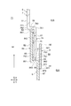
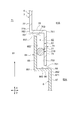
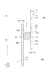
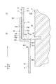
- FIG. 1 is a schematic sectional view schematically showing the configuration of a turbocharger including a turbine housing according to an embodiment of the present invention.
- FIG. 2 is a schematic sectional view of the turbine housing according to the embodiment of the present invention.
- the arrows in FIG. 2 and FIGS. 3 to 11 described later indicate the flow direction of the exhaust gas.
- a turbocharger 1 according to some embodiments includes a rotating shaft 11, a turbine wheel 12 attached to the rotating shaft 11, and a turbine housing 2 configured to house the turbine wheel 12.
- a turbine housing 2 configured to house the turbine wheel 12.
- the turbocharger 1 rotates the turbine wheel 12 by the exhaust gas introduced from the internal combustion engine (combustion device) such as an engine, and rotates the impeller of the compressor connected to the rotary shaft 11 via the rotary shaft 11, thereby compressing the turbine wheel 12.
- the air is generated and supplied to the internal combustion engine.
- the turbocharger 1 further includes a variable nozzle vane mechanism 13 configured to be able to adjust the amount of exhaust gas sent to the turbine wheel 12, as shown in FIG. 1. That is, the turbocharger 1 according to the illustrated embodiment is a VG (Variable Geometry) turbocharger. In addition, in some other embodiments, the turbocharger 1 may not include the variable nozzle vane mechanism 13.
- the variable nozzle vane mechanism 13 is configured to be adjustable to a nozzle opening degree instructed by a control device (not shown). By adjusting the nozzle opening degree and adjusting the amount of exhaust gas sent to the turbine wheel 12, the turbine wheel is adjusted. 12 is adjusted to an appropriate number of revolutions. As shown in FIG. 1, the variable nozzle vane mechanism 13 is arranged radially outside the turbine wheel 12 and is housed in the turbine housing 2. In other words, the turbine housing 2 is configured to house the variable nozzle vane mechanism 13 radially outside the turbine wheel 12.
- the turbocharger 1 includes, as shown in FIG. 1, a bearing 14 that rotatably supports the rotating shaft 11, and a bearing housing 15 configured to accommodate the bearing 14. Is further provided.
- the turbine housing 2 is connected and fixed to the bearing housing 15 by a fastening device (not shown). Examples of the fastening device include bolts, nuts, and V clamps.
- the turbine housing 2 includes an outer housing 3 that forms an outer shell of the turbine housing 2 and an inner housing 6 that is arranged inside the outer housing 3.
- the outer housing 3 includes a scroll portion 4 and a tubular exhaust gas introducing portion 5, as shown in FIG.
- the inner housing 6 includes an inner scroll member 7 made of a sheet metal and an inlet member 8 made of a sheet metal which is a separate body from the inner scroll member 7.
- the turbine housing 2 described above includes the scroll portion 4, the exhaust gas introduction portion 5, the inner scroll member 7, and the inlet member 8.
- the scroll portion 4 is configured to define the spiral space 41 inside.
- the tubular exhaust gas introduction part 5 is formed with an exhaust gas introduction port 51 for introducing the exhaust gas and defines a communication passage 52 connecting the exhaust gas introduction port 51 and the spiral space 41 therein. ..
- the outer housing 3 is made of cast metal, and the exhaust gas introducing portion 5 is formed integrally with the scroll portion 4.
- each of the scroll portion 4 and the exhaust gas introduction portion 5 is made of a metal such as cast iron or stainless cast steel.
- each of the inner scroll member 7 and the inlet member 8 is formed by sheet metal working of a thin plate member made of heat resistant steel (metal) such as austenitic stainless steel.
- a direction in which the axis line LB of the exhaust gas introducing portion 5 extends is defined as an axial direction X
- a direction that passes through the axis line LB of the exhaust gas introducing portion 5 and is orthogonal to the axis line LB is defined as a radial direction Y.
- upstream and downstream are based on the flow direction of the exhaust gas flowing inside the inner housing 6.
- the axis LA of the rotating shaft 11 described above extends along a direction orthogonal to the axial direction X and the radial direction Y, as shown in FIG.
- the spiral space 41 described above extends around the axis LA of the rotary shaft 11 along the circumferential direction of the axis LA.
- the inner scroll member 7 is disposed in the spiral space 41 of the scroll portion 4 to form a first heat insulating space 41A between the inner surface 42 of the scroll portion 4 and the exhaust gas inlet
- the spiral flow passage 71 through which the exhaust gas flowing from 51 flows is defined inside.
- the first heat insulating space 41A is formed by the inner surface 42 of the scroll portion 4 and the outer surface 72 of the inner scroll member 7.
- the spiral flow passage 71 is formed by the inner surface 73 of the inner scroll member 7.
- the outer surface 72 of the inner scroll member 7 faces the first heat insulating space 41A, and the inner surface 73 faces the spiral flow passage 71.
- the inlet member 8 is arranged in the communication passage 52 of the exhaust gas introducing portion 5 to form the second heat insulating space 52A between the inner surface 53 of the exhaust gas introducing portion 5 and the exhaust gas introducing portion. It is configured to internally define a communication channel 81 that connects the mouth 51 and the spiral channel 71.
- the second heat insulating space 52A is formed by the inner surface 53 of the exhaust gas introducing portion 5 and the outer surface 82 of the inlet member 8.
- the communication channel 81 is formed by the inner surface 83 of the inlet member 8.
- the outer surface 82 of the inlet member 8 faces the second heat insulating space 52A, and the inner surface 83 faces the communication flow path 81.
- the first heat insulating space 41A and the second heat insulating space 52A communicate with each other. Further, the spiral flow passage 71 and the communication flow passage 81 communicate with each other.
- the thermal energy of the exhaust gas flowing through the spiral flow passage 71 and the communication flow passage 81 changes from the inner housing 6 (the inner scroll member 7 and the inlet member 8) to the outer housing. 3 (scroll part 4, exhaust gas introducing part 5, etc.) and is provided in order to suppress being absorbed by the outer housing 3.
- the exhaust gas introducing portion 5 is formed in a tubular shape that extends along the axial direction X and has both ends opened, as shown in FIG.
- the opened upstream end portion 54 has a flange portion 55 protruding outward in the radial direction Y.
- the inlet member 8 is formed in a tubular shape that extends along the axial direction X and is open at both ends, as shown in FIG. Has a flange portion 801 protruding outward in the radial direction Y.
- the inlet member 8 is attached to the exhaust gas introducing portion 5 by sandwiching the flange portion 801 between the flange portion 55 and the other member when the flange portion 55 of the exhaust gas introducing portion 5 and the other member are fastened. Supported.
- the outer peripheral edge 70 positioned radially outward of the axis LA, the outer peripheral edge 131 of the variable nozzle vane mechanism 13, the scroll portion 4, and the bearing. It is supported by the scroll portion 4 by being sandwiched by the housing 15.
- the outer housing 3 further includes an exhaust gas discharge part 31, as shown in FIG. 1.
- the exhaust gas discharge part 31 is formed in a tubular shape that extends along the direction in which the axis LA of the rotary shaft 11 extends and has both ends open.
- the exhaust gas discharge part 31 has an exhaust gas discharge port 321 for discharging exhaust gas at the downstream end 32, and an exhaust flow path 311 for sending the exhaust gas driving the turbine wheel 12 to the exhaust gas discharge port 321. It is configured to be internally defined.
- the exhaust gas introduced into the turbine housing 2 from the exhaust gas introduction port 51 of the exhaust gas introduction unit 5 sequentially passes through the communication flow passage 81 of the inlet member 8 and the spiral flow passage 71 of the inner scroll member 7. After flowing, it is sent to the turbine wheel 12 via the variable nozzle vane mechanism 13.
- the exhaust gas that drives the turbine wheel 12 flows through the exhaust passage 311 and then is exhausted to the outside of the turbine housing 2 from the exhaust gas exhaust port 321 of the exhaust gas exhaust unit 31.
- the internal combustion engine described above includes a gasoline engine, and the temperature of the exhaust gas introduced into the turbine housing 2 is 800°C to 1000°C.
- the turbine housing 2 includes, for example, as shown in FIG. 2, the above-mentioned scroll portion 4, the above-mentioned exhaust gas introduction portion 5, the above-mentioned inner scroll member 7, and the above-mentioned inlet member 8. , Is provided.
- the upstream end 74 of the inner scroll member 7 and the downstream end 84 of the inlet member 8 overlap each other in the axial direction X of the exhaust gas introduction unit 5.
- the turbine housing 2 has the overlapping portion 61 in which the upstream end portion 74 and the downstream end portion 84 overlap in the axial direction X.
- each of the upstream end portion 74 and the downstream end portion 84 extends along the axial direction X of the exhaust gas introducing portion 5.
- the upstream end portion 74 is located outside the downstream end portion 84 in the radial direction Y of the exhaust gas introducing portion 5. Note that, in some other embodiments, the upstream end portion 74 may be located on the inner side in the radial direction Y of the exhaust gas introducing portion 5 than the downstream end portion 84. Further, in the illustrated embodiment, as shown in FIG. 2, the overlapping portion 61 is formed over the entire circumference in the circumferential direction of the axis line LB of the exhaust gas introducing portion 5. In addition, in some other embodiments, the overlapping portion 61 described above may be formed in a part in the circumferential direction of the axis line LB of the exhaust gas introducing portion 5. These two points are the same in some embodiments described later.
- the turbine housing 2 is arranged in the scroll portion 4, the exhaust gas introduction portion 5, and the spiral space 41 of the scroll portion 4, and the first heat insulating space is provided between the scroll portion 4, the inner space 42 of the scroll portion 4.
- An inlet made of sheet metal which is arranged in the communication passage 52 of the exhaust gas introducing portion 5 and forms a second heat insulating space 52A between the inner scroll member 7 of sheet metal forming 41A and the communication passage 52 of the exhaust gas introducing portion 5.
- the exhaust gas introduced into the turbine housing 2 is defined inside the inner housing 6, that is, inside the inlet member 8 made of sheet metal, and the inner scroll made of sheet metal. It flows through a spiral flow path 71 defined inside the member 7. Since the sheet metal inlet member 8 and the sheet metal inner scroll member 7 each have a small heat capacity, the heat of the exhaust gas when the exhaust gas introduced into the turbine housing 2 flows through the communication passage 81 and the spiral passage 71. It is possible to suppress the dissipation of energy to the outside (inner housing 6), and it is possible to suppress the temperature of the exhaust gas flowing in the turbine housing 2 from decreasing.
- the upstream end portion 74 of the inner scroll member 7 and the downstream end portion 84 of the inlet member 8 overlap along the axial direction X of the exhaust gas introducing portion 5. Therefore, the gap 62 that can be formed in the overlapping portion 61 of the upstream end portion 74 of the inner scroll member 7 and the downstream end portion 84 of the inlet member 8 is narrower than other portions and has a large flow resistance. Therefore, the structure is such that exhaust gas does not easily pass through. Therefore, according to the above configuration, the exhaust gas flowing inside the inner housing 6 passes between the upstream end portion 74 of the inner scroll member 7 and the downstream end portion 84 of the inlet member 8 and passes outside the inner housing 6. Can be suppressed.
- the high temperature strength of the turbine housing 2 is improved by reducing the amount of exhaust gas flowing out of the inner housing 6 and reducing the thermal energy of the exhaust gas absorbed by the outer housing 3 (scroll portion 4 and exhaust gas introducing portion 5). Can be made.
- FIGS. 3 to 11 is a schematic partial enlarged cross-sectional view showing an enlarged overlapping portion of the turbine housing according to the embodiment of the present invention.
- FIGS. 3 to 11 shows the portion A shown in FIG. 2 in an enlarged manner.
- the upstream end 74 of the inner scroll member 7 described above intersects (orthogonally intersects) the axial direction X of the exhaust gas introducing portion 5 (vertical direction in the drawings). ), and a scroll side tip portion 75 extending from the tip end 761 of the scroll side intersection portion 76 toward the upstream side (lower side in the drawing).
- FIGS. 3 to 9 shows the upstream end 74 of the inner scroll member 7 described above intersects (orthogonally intersects) the axial direction X of the exhaust gas introducing portion 5 (vertical direction in the drawings).
- a scroll side tip portion 75 extending from the tip end 761 of the scroll side intersection portion 76 toward the upstream side (lower side in the drawing).
- the downstream end portion 84 of the above-described inlet member 8 has an inlet-side intersecting portion 86 extending along a direction intersecting (orthogonal to) the axial direction X, and an inlet.
- the inlet-side tip portion 85 extending from the tip 861 of the side intersection portion 86 toward the downstream side (upper side in the drawing) is included.
- the scroll-side tip portion 75 and the inlet-side tip portion 85 overlap each other in the axial direction X of the exhaust gas introducing portion 5.
- the leading end 851 of the inlet-side leading end portion 85 is configured to be located between the leading end 761 and the base end 762 of the scroll-side intersecting portion 76 in the radial direction Y of the exhaust gas introducing portion 5.
- the tip end 751 of the scroll side tip end portion 75 is located between the tip end 861 and the base end 862 of the inlet side intersection portion 86 in the radial direction Y of the exhaust gas introducing portion 5. It is configured.
- the scroll-side intersecting portion 76 has an inner scroll member 7 whose base end 762 extends toward the upstream side along the axial direction X of the exhaust gas introducing portion 5, as shown in FIG. 3, for example. Is connected to the tip end 771 of the scroll-side base portion 77.
- the inlet-side intersecting portion 86 has an inlet-side root portion 87 of the inlet member 8 whose base end 862 extends toward the downstream side along the axial direction X of the exhaust gas introducing portion 5. Is connected to the tip 871 of the.
- the gap 62 that can be formed in the exhaust gas extends along the axial direction X of the exhaust gas introducing portion 5 and extends in a direction intersecting (orthogonal to) the axial direction X of the exhaust gas introducing portion 5 as shown in FIG. 3, for example. It has a gap inlet 63 and a gap outlet 64 that are opened.
- the inner surface 752 (wall surface) of the scroll side tip portion 75 and the outer surface 852 (wall surface) of the inlet side tip portion 85 face each other.
- the flow direction of the exhaust gas formed in the portion and flowing through the main body of the gap 62 is opposite to the flow direction of the exhaust gas flowing inside the inner housing 6.
- the gap inlet 63 is formed by the inner surface 763 (wall surface) of the scroll-side intersecting portion 76 and the tip 851 of the inlet-side tip 85.
- the gap outlet 64 is formed by the inner surface 863 (wall surface) of the inlet-side intersecting portion 86 and the tip 751 of the scroll-side tip portion 75.
- the gap inlet 63 is provided at the downstream end (one end) of the gap 62 in the extending direction of the body portion, and the gap outlet 64 is provided at the upstream end (other end) of the gap 62 in the extending direction of the body portion.
- Each of the gap inlet 63 and the gap outlet 64 extends in a direction intersecting (orthogonal to) the extending direction of the main body of the gap 62.
- the upstream end portion 74 (the scroll side tip portion 75 and the scroll side intersection portion 76) of the inner scroll member 7 and the downstream end portion 84 of the inlet member 8 (the inlet side tip portion 85 and the inlet side).
- the gap 62 that can be formed between the crossing portion 86) extends along the axial direction X of the exhaust gas introducing portion 5 as shown in FIG. 3, and the gap inlet 63 and the gap outlet 64 are respectively formed.
- the opening is formed in a direction intersecting the axial direction X of the exhaust gas introducing portion 5. Since the gap 62 changes in such a manner that the flow direction of the exhaust gas bends a plurality of times, the exhaust gas has a structure that does not easily pass through. Therefore, according to the above configuration, the exhaust gas flowing inside the inner housing 6 can be suppressed from flowing out of the inner housing 6 through the gap 62.
- the inlet member 8 described above is configured such that the tip 851 of the inlet-side tip portion 85 abuts on the scroll-side intersecting portion 76 of the inner scroll member 7, as shown in FIG. 4. In this case, the downstream end 84 of the inlet member 8 is supported by the upstream end 74 of the inner scroll member 7.
- the tip end 851 of the inlet-side tip portion 85 abuts the scroll-side crossing portion 76, and the above-described gap inlet 63 is closed, so that the exhaust gas flowing inside the inner housing 6 is prevented from flowing into the inner scroll member. It is possible to prevent it from flowing out of the inner housing 6 through the gap 62 formed between the upstream end portion 74 of 7 and the downstream end portion 84 of the inlet member 8.
- the inner surface 752 (wall surface) of the scroll-side tip portion 75 is the outer surface 852 of the inlet-side tip portion 85 of the inlet member 8 described above. It is configured to come into contact with the (wall surface) along the axial direction X of the exhaust gas introducing portion 5.
- the downstream end 84 of the inlet member 8 is supported by the upstream end 74 of the inner scroll member 7.
- the inner surface 752 (wall surface) of the scroll-side tip portion 75 abuts the outer surface 852 (wall surface) of the inlet-side tip portion 85 along the axial direction X of the exhaust gas introducing portion 5, so the inner scroll member
- the above-described gap 62 is not formed between the upstream end 74 of No. 7 and the downstream end 84 of the inlet member 8.
- the contact area between the inner scroll member 7 and the inlet member 8 can be made wider than in the case where the tip 851 of the inlet side tip portion 85 abuts on the scroll side intersecting portion 76. It is possible to more reliably prevent the exhaust gas flowing inside the inner housing 6 from passing through the gap 62 and flowing out of the inner housing 6.
- the turbine housing 2 described above further includes an attachment plate member 9, as shown in FIG.
- the attachment plate member 9 is located outside the exhaust gas introducing portion 5 in the radial direction Y with respect to the scroll-side tip portion 75 and the inlet-side tip portion 85 described above, and the scroll-side tip portion 75 and the inlet-side tip portion.
- Each of 85 is configured to overlap along the axial direction X of the exhaust gas introducing portion 5.
- the attachment plate member 9 is configured to be supported by the inner scroll member 7.
- the attachment plate member 9 extends along the axial direction X of the exhaust gas introducing portion 5 as shown in FIG. 6, and the inner surface 911 of the upstream side portion 91 in the extending direction is provided with an inlet.
- the upstream side portion 91 is fixed to the inlet-side root portion 87 of the inlet member 8 while being in contact with the outer surface 872 of the inlet-side root portion 87 of the member 8.
- the downstream portion 92 of the attachment plate member 9 overlaps with each of the scroll-side tip portion 75 and the inlet-side tip portion 85 along the axial direction X of the exhaust gas introducing portion 5.
- exhaust gas flows in a direction opposite to the direction of the main body of the gap 62.
- the second gap 65 is formed.
- the second gap 65 is included in the gap 62 described above and communicates with the gap outlet 64.
- the attachment plate member 9 is formed by sheet metal working a thin plate member made of heat resistant steel (metal) such as austenitic stainless steel.
- the attachment plate member 9 is supported by the inner scroll member 7, and is located outside the exhaust gas introducing portion 5 in the radial direction Y with respect to each of the scroll side tip portion 75 and the inlet side tip portion 85.
- the scroll-side tip portion 75 and the inlet-side tip portion 85 overlap with each other along the axial direction X of the exhaust gas introducing portion 5.
- Such an attachment plate member 9 can extend the gap 62 on the downstream side of the gap outlet 64 along the axial direction X of the exhaust gas introducing portion 5.
- the gap 62 has a structure in which the exhaust gas is more difficult to pass through because the number of times that the flow direction of the exhaust gas changes so as to bend increases and the entire length of the gap 62 increases. Therefore, according to the above configuration, the exhaust gas flowing inside the inner housing 6 can be suppressed from flowing through the gap 62 to the outside of the inner housing 6.
- the turbine housing 2 described above is placed in contact with each of the scroll-side tip portion 75 and the inlet-side tip portion 85 described above, as shown in FIGS.
- the gap filling member 21 configured to be able to close the gap 62 provided between the scroll-side tip portion 75 and the inlet-side tip portion 85 is provided.
- the downstream end 84 of the inlet member 8 is supported by the upstream end 74 of the inner scroll member 7 via the gap filling member 21.
- the gap filling member 21 extends along the axial direction X of the exhaust gas introducing portion 5, and is provided on the inner surface 752 (wall surface) of the scroll-side tip portion 75 and the outer surface 852 of the inlet-side tip portion 85. It is composed of the interfering substances 21A which are in contact with the respective (wall surfaces).
- the interferer 21A has a rectangular cross section.
- the interferer 21A includes a heat insulating material having a high heat resistant temperature.
- the interferer 21A includes a woven or non-woven fabric made of ceramic fibers such as silica fibers or alumina fibers.
- the gap filling member 21 is composed of the seal material 21B that is in contact with each of the inner surface 752 (wall surface) of the scroll-side tip portion 75 and the outer surface 852 (wall surface) of the inlet-side tip portion 85. ..
- the sealing material 21B has a circular cross section.
- the sealing material 21B is formed in an arc shape or an annular shape extending along the circumferential direction of the axis line LB of the exhaust gas introducing portion 5.
- the sealing material 21B includes a heat-resistant rope-shaped member, preferably a fiber rope made of a heat-resistant fiber such as carbon fiber or ceramic fiber.
- the gap filling member 21 is arranged in contact with each of the scroll side tip portion 75 and the inlet side tip portion 85, and is provided between the scroll side tip portion 75 and the inlet side tip portion 85. Since the gap 62 provided can be closed, the exhaust gas flowing inside the inner housing 6 can be prevented from flowing out of the inner housing 6 through the gap 62 described above.
- the turbine housing 2 described above includes a metallic seal member 22, as shown in FIG.
- the seal member 22 is arranged in contact with each of the scroll-side intersecting portion 76 and the inlet-side intersecting portion 86, and is configured to be expandable and contractable along the axial direction X of the exhaust gas introducing portion 5.
- the downstream end 84 of the inlet member 8 is supported by the upstream end 74 of the inner scroll member 7 via the seal member 22.
- the gap 62 is closed by the seal member 22.
- the seal member 22 is formed in an arc shape or an annular shape around the axis line LB of the exhaust gas introducing portion 5 and has a V-shaped cross section along the axis line LB, as shown in FIG. 9. It consists of a V-seal.
- the seal member 22 is configured such that the end portions 222 and 223 on the opening side are arranged so as to face the inside in the radial direction Y of the exhaust gas introducing portion 5. In other words, the end portions 222 and 223 on the opening side are located on the inner side in the radial direction Y with respect to the connecting portion 221 that connects the end portion 222 and the end portion 223.
- the seal member 22 is configured to elastically deform when compressed in the axial direction X, as shown in FIG. 9.
- the seal member 22 is arranged so that the end portion 222 contacts the inner surface 763 (wall surface) of the scroll side intersection portion 76, and the end portion 223 contacts the outer surface 863 (wall surface) of the inlet side intersection portion 86. ..
- the seal member 22 is arranged between the inner surface 763 of the scroll side intersection portion 76 and the outer surface 863 of the inlet side intersection portion 86 in a compressed state along the axial direction X. In this case, the restoring force of the seal member 22 can close the gap 62 more reliably.
- the seal member 22 may have a C-shaped or E-shaped cross section.
- the metallic seal member 22 is arranged in contact with each of the scroll-side intersecting portion 76 and the inlet-side intersecting portion 86, and is expandable/contractible along the axial direction X of the exhaust gas introducing portion 5.
- the metal seal member 22 extends along the axial direction X of the exhaust gas introducing portion 5 due to the pressure of the exhaust gas introduced into the gap 62, and comes into close contact with the scroll side intersection portion 76 and the inlet side intersection portion 86, The gap 62 provided between the scroll-side intersection 76 and the entrance-side intersection 86 can be closed more reliably. Therefore, according to the above configuration, it is possible to prevent the exhaust gas flowing inside the inner housing 6 from flowing out of the inner housing 6 through the gap 62.
- the scroll-side tip portion 75 described above is configured to be located outside the inlet-side tip portion 85 described above in the radial direction Y of the exhaust gas introduction portion 5. Has been done.
- the scroll-side tip portion 75 is located outside the inlet-side tip portion 85 in the radial direction Y of the exhaust gas introducing portion 5.
- the gap 62 that may be formed in the overlapping portion 61 between the scroll-side tip portion 75 and the inlet-side tip portion 85 is such that the flow direction of the exhaust gas flowing through the gap 62 is the flow of the exhaust gas flowing inside the inner housing 6. Since it is configured to be along the direction opposite to the direction, it is difficult for exhaust gas to pass through. Therefore, according to the above configuration, the exhaust gas flowing inside the inner housing 6 can be more effectively suppressed from flowing out of the inner housing 6 through the gap 62.
- the upstream side end portion 74 of the above-described inner scroll member 7 is a scroll side extending toward the upstream side along the axial direction X of the exhaust gas introducing portion 5. Including the tip portion 75A.
- the downstream side end portion 84 of the above-described inlet member 8 includes an inlet side front end portion 85A extending toward the downstream side along the axial direction X of the exhaust gas introducing portion 5.
- the turbine housing 2 described above is arranged in contact with the scroll-side tip portion 75A and the inlet-side tip portion 85A, and closes the gap 62 provided between the scroll-side tip portion 75A and the inlet-side tip portion 85A.
- the above-described gap filling member 21 configured as possible is provided. In this case, the downstream end 84 of the inlet member 8 is supported by the upstream end 74 of the inner scroll member 7 via the gap filling member 21.
- the upstream end portion 74 of the inner scroll member 7 does not include the scroll side intersection portion 76
- the downstream end portion 84 of the inlet member 8 described above does not include the scroll side intersection portion 76.
- the entrance side intersection 86 is not included. That is, the scroll side tip portion 75A extends from the tip end 771 of the scroll side root portion 77 toward the upstream side along the axial direction X of the exhaust gas introducing portion 5. Further, the above-mentioned inlet-side tip portion 85A extends from the tip end 871 of the inlet-side root portion 87 toward the upstream side along the axial direction X of the exhaust gas introducing portion 5.
- each of the gap inlet 63A and the gap outlet 63B of the gap 62 described above is opened along the extending direction of the main body of the gap 62, as shown in FIG.
- the scroll-side tip portion 75A is configured to be located outside the inlet-side tip portion 85A in the radial direction Y of the exhaust gas introducing portion 5.
- the gap 62 that may be formed in the overlapping portion 61 of the scroll-side tip portion 75A and the inlet-side tip portion 85A is such that the flow direction of the exhaust gas flowing through the gap 62 is the flow of the exhaust gas flowing inside the inner housing 6. Since it is configured to be along the direction opposite to the direction, it is difficult for exhaust gas to pass through.
- the gap filling member 21 is composed of the sealing material 21B which is in contact with each of the inner surface 752 (wall surface) of the scroll side tip portion 75A and the outer surface 852 (wall surface) of the inlet side tip portion 85A. ..
- the gap filling member 21 is made of the interferer 21A described above. That is, instead of the seal member 21B in FIG. 10, the above-described interference object 21A as shown in FIG. 7 is formed on the inner surface 752 (wall surface) of the scroll side tip portion 75A and the outer surface 852 (wall surface) of the inlet side tip portion 85A. It may be adapted to contact each other.
- the gap filling member 21 is arranged in contact with each of the scroll side tip portion 75A and the inlet side tip portion 85A, and is provided between the scroll side tip portion 75A and the inlet side tip portion 85A. Since the gap 62 provided can be closed, the exhaust gas flowing inside the inner housing 6 can be prevented from flowing out of the inner housing 6 through the gap 62.
- the upstream end portion 74 of the inner scroll member 7 described above extends along a direction intersecting (orthogonal to) the axial direction X of the exhaust gas introducing portion 5.
- a flange portion 78 inserted into the groove 34 formed in the inner surface 33 of the outer housing 3 (turbine housing 2) and a scroll-side tip portion 75B extending from the inner peripheral end 782 of the flange portion 78 toward the downstream side.
- the downstream end portion 84 of the above-described inlet member 8 includes the above-mentioned inlet-side intersection portion 86 and the above-mentioned inlet-side tip portion 85.
- the turbine housing 2 is configured such that at least one of the collar portion 78 and the inlet-side tip portion 85, or the scroll-side tip portion 75B and the inlet-side intersection portion 86 abut.
- the outer peripheral end 781 of the collar portion 78 is fitted in the groove 34.
- the scroll-side tip portion 75B has an upstream end connected to the inner peripheral end 782 of the collar portion 78, and a downstream end connected to the tip 771 of the scroll-side root portion 77 described above.
- the entrance-side crossing portion 86 has a base end 862 connected to the tip end 871 of the entrance-side root portion 87 described above.
- the inner peripheral end 782 of the collar portion 78 is located outside the tip 861 of the inlet-side crossing portion 86 in the radial direction Y of the exhaust gas introducing portion 5, and is larger than the base end 862 of the inlet-side crossing portion 86 in the diameter of the exhaust gas introducing portion 5. It is configured to be located inside the direction Y.
- the outer surface 863 of the inlet-side crossing portion 86 is configured to contact the wall surface 783 located on the upstream side of the collar portion 78 along the radial direction Y. There is. In some other embodiments, as shown in FIG. 11, the outer surface 852 of the inlet side tip portion 85 is configured to abut the inner surface 752 of the scroll side tip portion 75B along the axial direction X. ..
- the flange portion 78 of the inner scroll member 7 is inserted into the groove 34 formed in the inner surface 33 of the outer housing 3 (turbine housing 2), so that the upstream end of the inner scroll member 7 can be prevented.
- the part 74 can be fixed to the outer housing 3.
- the upstream end portion 74 (the flange portion 78, the scroll side tip portion 75B) of the inner scroll member 7 fixed to the outer housing 3 does not shift even if a pressing force is applied. Therefore, it is possible to bring the downstream end portion 84 (the inlet side tip portion 85, the inlet side intersecting portion 86) of the inlet member 8 into close contact with the upstream end portion 74 of the inner scroll member 7 when they are brought into contact with each other.
- the exhaust gas flowing inside the inner housing 6 passes through the gap 62 formed between the upstream end 74 of the inner scroll member 7 and the downstream end 84 of the inlet member 8 to the outside of the inner housing 6. It can be more reliably prevented from flowing out.
- the turbocharger 1 includes the turbine wheel 12 described above and the turbine housing 2 described above that houses the turbine wheel 12, as shown in FIG. 1.
- the turbine housing 2 includes the scroll portion 4, the exhaust gas introduction portion 5, the inner scroll member 7, and the inlet member 8 described above, and thus the turbine housing 2 It is possible to reduce the internal leak and improve the high temperature strength of the turbine housing 2.
- the turbocharger 1 including such a turbine housing 2 can be operated even if the exhaust gas introduced into the turbine housing 2 has a high temperature.
- the present invention is not limited to the above-described embodiment, and includes a form in which the above-described embodiment is modified and a form in which these forms are appropriately combined.
Landscapes
- Engineering & Computer Science (AREA)
- Mechanical Engineering (AREA)
- General Engineering & Computer Science (AREA)
- Chemical & Material Sciences (AREA)
- Combustion & Propulsion (AREA)
- Chemical Kinetics & Catalysis (AREA)
- General Chemical & Material Sciences (AREA)
- Supercharger (AREA)
Abstract
タービンハウジングは、渦状空間を内部に画定するスクロール部と、排ガス導入口が形成され、排ガス導入口と渦状空間とを繋ぐ連絡通路を内部に画定する筒状の排ガス導入部と、渦状空間に配置されて、スクロール部の内面との間に第1の断熱空間を形成するとともに、排ガス導入口から流入した排ガスが流れる渦状流路を内部に画定する板金製の内側スクロール部材と、内側スクロール部材とは別体である板金製の入口部材であって、連絡通路に配置されて、排ガス導入部の内面との間に第2の断熱空間を形成するとともに、排ガス導入口と渦状流路とを繋ぐ連絡流路を内部に画定する板金製の入口部材と、を備え、内側スクロール部材の上流側端部と、入口部材の下流側端部とは、排ガス導入部の軸方向に沿って重複している。
Description
本開示は、タービンハウジング、タービンハウジングを備えるターボチャージャに関する。
従来、エンジンから導入される排ガスのエネルギーを利用してタービンホイールを回転させ、該タービンホイールと同軸上に設けられたコンプレッサホイールを回転させることで、吸気マニホールドに圧縮空気を供給し、エンジン出力の向上を図るターボチャージャが知られている。
ターボチャージャのタービンホイールは、タービンハウジングに収容される。タービンハウジングは、一般的には鋳造により製造されているため、鋳型内での湯流れを考慮して肉厚が厚く、熱容量が大きくなっている。このような鋳造製のタービンハウジングは、エンジン始動時において、タービンハウジング内を流れる排ガスの熱エネルギーがタービンハウジングに吸収されるため、排ガスの温度が下がる。排ガスの温度が下がると、タービン下流に位置する排気浄化触媒の温度上昇を妨げる虞がある。このため、近年、タービンハウジングの熱容量低減や軽量化のために、薄く平らに形成された金属板から板金加工することで製作される板金製のタービンハウジングが提案されている。
特許文献1には、渦状空間を形成するハウジング部の内周面と、渦状の排ガス流路を形成するハウジング側インナーケーシングの外周面との間に遮熱空間が形成されるタービンハウジングが開示されている。
特許文献2には、渦状空間を形成するハウジング部に隣接した入口接続部に挿入される薄肉漏斗状の入口側インナーケーシング(スリーブ)と、ハウジング部に挿入されるハウジング側インナーケーシング(スリーブ)と、が開示されている。
特許文献1に記載された発明のように、ハウジング部のみにハウジング側インナーケーシングインナーケーシングを配置すると、タービンホイールに導入される前の排ガスの熱エネルギーが、ハウジングに隣接した入口接続部に吸収され、排ガスの温度が下がる虞がある。この場合には、タービンホイールに導入される排ガスの温度が下がるので、タービンホイールの性能が低下する虞がある。また、入口接続部は、排ガスからの熱入力が大きく、高温となり易いので、タービンハウジングの高温強度を確保することが困難となる虞がある。
特許文献2に記載された発明には、ハウジング部および入口接続部の夫々に個別にインナーケーシング(ハウジング側インナーケーシング、入口側インナーケーシング)を配置することが開示されているが、ハウジング側インナーケーシングと入口側インナーケーシングとの接続については具体的には開示されていない。ハウジング側インナーケーシングと入口側インナーケーシングとの間に隙間が空いていると、上記隙間からインナーケーシングの外部に排ガスが漏れ出して(内部リーク)、ハウジング部や入口接続部への排ガスからの熱入力が大きくなるので、タービンハウジングの高温強度を確保することが困難となる虞がある。
上述した事情に鑑みて、本発明の少なくとも一実施形態の目的は、内部リークを低減させ、高温強度を向上させることができるタービンハウジングを提供することにある。
(1)本発明の少なくとも一実施形態にかかるタービンハウジングは、
タービンホイールを収容するためのタービンハウジングであって、
渦状空間を内部に画定するように構成されたスクロール部と、
排ガスを導入するための排ガス導入口が形成されるとともに、上記排ガス導入口と上記渦状空間とを繋ぐ連絡通路を内部に画定するように構成された筒状の排ガス導入部と、
上記渦状空間に配置されて、上記スクロール部の内面との間に第1の断熱空間を形成するとともに、上記排ガス導入口から流入した排ガスが流れる渦状流路を内部に画定するように構成された板金製の内側スクロール部材と、
上記内側スクロール部材とは別体である板金製の入口部材であって、上記連絡通路に配置されて、上記排ガス導入部の内面との間に第2の断熱空間を形成するとともに、上記排ガス導入口と上記渦状流路とを繋ぐ連絡流路を内部に画定するように構成された板金製の入口部材と、を備え、
上記内側スクロール部材の上流側端部と、上記入口部材の下流側端部とは、上記排ガス導入部の軸方向に沿って重複している。
タービンホイールを収容するためのタービンハウジングであって、
渦状空間を内部に画定するように構成されたスクロール部と、
排ガスを導入するための排ガス導入口が形成されるとともに、上記排ガス導入口と上記渦状空間とを繋ぐ連絡通路を内部に画定するように構成された筒状の排ガス導入部と、
上記渦状空間に配置されて、上記スクロール部の内面との間に第1の断熱空間を形成するとともに、上記排ガス導入口から流入した排ガスが流れる渦状流路を内部に画定するように構成された板金製の内側スクロール部材と、
上記内側スクロール部材とは別体である板金製の入口部材であって、上記連絡通路に配置されて、上記排ガス導入部の内面との間に第2の断熱空間を形成するとともに、上記排ガス導入口と上記渦状流路とを繋ぐ連絡流路を内部に画定するように構成された板金製の入口部材と、を備え、
上記内側スクロール部材の上流側端部と、上記入口部材の下流側端部とは、上記排ガス導入部の軸方向に沿って重複している。
上記(1)の構成によれば、タービンハウジングは、スクロール部と、排ガス導入部と、スクロール部の渦状空間に配置されて、スクロール部の内面との間に第1の断熱空間を形成する板金製の内側スクロール部材と、排ガス導入部の連絡通路に配置されて、排ガス導入部の内面との間に第2の断熱空間を形成する板金製の入口部材と、を備える。つまり、タービンハウジングは、アウターハウジング(スクロール部および排ガス導入部)の内部に、断熱空間(第1の断熱空間、第2の断熱空間)を介して、インナーハウジング(板金製の内側スクロール部材および入口部材)が配置される二重構造になっている。このようなタービンハウジングは、タービンハウジング内に導入された排ガスが、インナーハウジングの内部、すなわち、板金製の入口部材の内部に画定される連絡流路、および板金製の内側スクロール部材の内部に画定される渦状流路を流れるようになっている。板金製の入口部材および板金製の内側スクロール部材の夫々は、熱容量が小さいため、タービンハウジング内に導入された排ガスが連絡流路および渦状流路を流れる際における、排ガスの熱エネルギーの外部への放熱を抑制することができ、タービンハウジング内を流れる排ガスの温度が下がるのを抑制することができる。
また、上記(1)の構成によれば、内側スクロール部材の上流側端部と、入口部材の下流側端部とは、排ガス導入部の軸方向に沿って重複している。このため、内側スクロール部材の上流側端部と入口部材の下流側端部との重複部に形成され得る隙間は、他の部分よりも狭く流路抵抗が大きなものになるので、排ガスが通り抜け難い構造になっている。よって、上記の構成によれば、インナーハウジングの内部を流れる排ガスが、内側スクロール部材の上流側端部と入口部材の下流側端部との間を通り、インナーハウジングの外部に流出することを抑制することができる。つまり、タービンハウジング内を流れる排ガスの内部リークを低減させることができる。また、インナーハウジングの外部に流出する排ガスの量を減らし、アウターハウジング(スクロール部や排ガス導入部)に吸収される排ガスの熱エネルギーを減らすことで、タービンハウジングの高温強度を向上させることができる。
(2)幾つかの実施形態では、上記(1)に記載のタービンハウジングであって、上記内側スクロール部材の上記上流側端部は、上記排ガス導入部の軸方向と交差する方向に沿って延在するスクロール側交差部と、上記スクロール側交差部の先端から上流側に向かって延在するスクロール側先端部と、を含み、上記入口部材の上記下流側端部は、上記排ガス導入部の軸方向と交差する方向に沿って延在する入口側交差部と、上記入口側交差部の先端から下流側に向かって延在する入口側先端部と、を含み、上記入口側先端部の先端が、上記排ガス導入部の径方向における上記スクロール側交差部の上記先端と基端との間に位置するように構成され、且つ、上記スクロール側先端部の先端が、上記排ガス導入部の径方向における上記入口側交差部の上記先端と基端との間に位置するように構成され、上記スクロール側先端部と、上記入口側先端部とは、上記排ガス導入部の軸方向に沿って重複している。
上記(2)の構成によれば、内側スクロール部材の上流側端部(スクロール側先端部およびスクロール側交差部)と、入口部材の下流側端部(入口側先端部および入口側交差部)との間に形成され得る隙間は、排ガス導入部の軸方向に沿って延在するとともに、隙間入口および隙間出口の夫々が排ガス導入部の軸方向に交差する方向に向かって開口するようになっている。このような隙間は、排ガスの流れ方向が複数回にわたり折れ曲がるように変化するので、排ガスが通り抜け難い構造になっている。よって、上記の構成によれば、インナーハウジングの内部を流れる排ガスが、上記隙間を通り、インナーハウジングの外部に流出することを抑制することができる。
(3)幾つかの実施形態では、上記(2)に記載のタービンハウジングであって、上記入口部材は、上記入口側先端部の先端が上記内側スクロール部材の上記スクロール側交差部に当接するように構成された。
上記(3)の構成によれば、入口側先端部の先端がスクロール側交差部に当接するので、インナーハウジングの内部を流れる排ガスが、内側スクロール部材の上流側端部と、入口部材の下流側端部との間に形成される隙間を通り、インナーハウジングの外部に流出することを防止することができる。
(4)幾つかの実施形態では、上記(2)又は(3)に記載のタービンハウジングは、上記スクロール側先端部および上記入口側先端部の夫々よりも上記排ガス導入部の径方向における外側に位置するとともに、上記スクロール側先端部および上記入口側先端部の夫々とは上記排ガス導入部の軸方向に沿って重複するように構成された添板部材であって、上記内側スクロール部材に支持されるように構成された添板部材をさらに備える。
上記(4)の構成によれば、添板部材は、内側スクロール部材に支持されるとともに、スクロール側先端部および入口側先端部の夫々よりも排ガス導入部の径方向における外側において、スクロール側先端部および入口側先端部の夫々に対して排ガス導入部の軸方向に沿って重複するようになっている。このような添板部材は、隙間出口よりも下流側に排ガス導入部の軸方向に沿って上記隙間を延ばすことができる。上記隙間は、排ガスの流れ方向が折れ曲がるように変化する回数が増えるとともに、隙間の全長が長くなるので、排ガスがより通り抜け難い構造になっている。よって、上記の構成によれば、インナーハウジングの内部を流れる排ガスが、上記隙間を通り、インナーハウジングの外部に流出することを抑制することができる。
(5)幾つかの実施形態では、上記(2)又は(3)に記載のタービンハウジングであって、上記内側スクロール部材は、上記スクロール側先端部の壁面が上記入口部材の上記入口側先端部の壁面に上記排ガス導入部の軸方向に沿って当接するように構成された。
上記(5)の構成によれば、スクロール側先端部の壁面が、入口側先端部の壁面に排ガス導入部の軸方向に沿って当接するので、内側スクロール部材の上流側端部と、入口部材の下流側端部との間に隙間が形成されないようになっている。また、上記の構成によれば、入口側先端部の先端がスクロール側交差部に当接する場合に比べて、内側スクロール部材と入口部材との接触面積を広くすることができるので、インナーハウジングの内部を流れる排ガスが、上記隙間を通り、インナーハウジングの外部に流出することをより確実に防止することができる。
(6)幾つかの実施形態では、上記(2)~(4)の何れかに記載のタービンハウジングは、上記スクロール側先端部および上記入口側先端部の夫々に接触して配置されるとともに、上記スクロール側先端部と上記入口側先端部との間に設けられる隙間を閉塞可能に構成された隙間充填部材をさらに備える。
上記(6)の構成によれば、隙間充填部材は、スクロール側先端部および入口側先端部の夫々に接触して配置されるとともに、スクロール側先端部と入口側先端部との間に設けられる隙間を閉塞可能に構成されているので、インナーハウジングの内部を流れる排ガスが、上記隙間を通り、インナーハウジングの外部に流出することを防止することができる。
(7)幾つかの実施形態では、上記(2)~(4)の何れかに記載のタービンハウジングは、上記スクロール側交差部および上記入口側交差部の夫々に接触して配置されるとともに、上記排ガス導入部の軸方向に沿って伸縮可能に構成された金属製のシール部材をさらに備える。
上記(7)の構成によれば、金属製のシール部材は、スクロール側交差部および入口側交差部の夫々に接触して配置されるとともに、排ガス導入部の軸方向に沿って伸縮可能に構成されている。上記金属製のシール部材は、隙間に導入される排ガスの圧力により排ガス導入部の軸方向に沿って伸びて、スクロール側交差部や入口側交差部に密着するので、スクロール側交差部および入口側交差部との間に設けられる隙間をより確実に閉塞することができる。このため、上記の構成によれば、インナーハウジングの内部を流れる排ガスが、上記隙間を通り、インナーハウジングの外部に流出することを防止することができる。
(8)幾つかの実施形態では、上記(2)~(7)の何れかに記載のタービンハウジングであって、上記スクロール側先端部は、上記入口側先端部よりも上記排ガス導入部の径方向外側に位置するように構成された。
上記(8)の構成によれば、スクロール側先端部は、入口側先端部よりも排ガス導入部の径方向外側に位置する。この場合には、スクロール側先端部と入口側先端部との重複部に形成され得る隙間は、上記隙間を流れる排ガスの流れ方向が、インナーハウジングの内部を流れる排ガスの流れ方向とは反対の方向に沿うように構成されるので、排ガスが通り抜け難くなっている。よって、上記の構成によれば、インナーハウジングの内部を流れる排ガスが、上記隙間を通り、インナーハウジングの外部に流出することをより効果的に抑制することができる。
(9)幾つかの実施形態では、上記(1)に記載のタービンハウジングであって、上記内側スクロール部材の上記上流側端部は、上記排ガス導入部の軸方向に沿って上流側に向かって延在するスクロール側先端部を含み、上記入口部材の上記下流側端部は、上記排ガス導入部の軸方向に沿って下流側に向かって延在する入口側先端部を含み、上記タービンハウジングは、上記内側スクロール部材の上記スクロール側先端部および上記入口部材の上記入口側先端部の夫々に接触して配置されるとともに、上記スクロール側先端部と上記入口側先端部との間に設けられる隙間を閉塞可能に構成された隙間充填部材をさらに備える。
上記(9)の構成によれば、隙間充填部材は、スクロール側先端部および入口側先端部の夫々に接触して配置されるとともに、スクロール側先端部と入口側先端部との間に設けられる隙間を閉塞可能に構成されているので、インナーハウジングの内部を流れる排ガスが、上記隙間を通り、インナーハウジングの外部に流出することを防止することができる。
(10)幾つかの実施形態では、上記(1)に記載のタービンハウジングであって、上記内側スクロール部材の上記上流側端部は、上記排ガス導入部の軸方向と交差する方向に沿って延在するとともに、上記タービンハウジングの内面に形成された溝に挿入される鍔部と、上記鍔部の内周端から下流側に向かって延在するスクロール側先端部と、を含み、上記入口部材の上記下流側端部は、上記排ガス導入部の軸方向と交差する方向に沿って延在する入口側交差部と、上記入口側交差部の下流端から下流側に向かって延在する入口側先端部と、を含み、上記鍔部と上記入口側先端部、又は上記スクロール側先端部と上記入口側交差部の少なくとも一方が当接するように構成された。
上記(10)の構成によれば、内側スクロール部材の鍔部をタービンハウジングの内面に形成された溝に挿入することで、内側スクロール部材の上流側端部をタービンハウジングに固定することができる。タービンハウジングに固定された内側スクロール部材の上流側端部(鍔部、スクロール側先端部)は、押圧力が加えられてもずれない。このため、内側スクロール部材の上流側端部に入口部材の下流側端部(入口側先端部、入口側交差部)を当接させる際により密着させることが可能となるので、インナーハウジングの内部を流れる排ガスが、内側スクロール部材の上流側端部と、入口部材の下流側端部との間に形成される隙間を通り、インナーハウジングの外部に流出することをより確実に防止することができる。
(11)本発明の少なくとも一実施形態にかかるターボチャージャは、タービンホイールと、上記(1)~(10)の何れかに記載のタービンハウジングと、を備える。
上記(11)の構成によれば、タービンハウジングが、上記スクロール部、上記排ガス導入部、上記内側スクロール部材および上記入口部材を備えるので、タービンハウジングの内部リークを低減させ、タービンハウジングの高温強度を向上させることができる。このようなタービンハウジングを備えるターボチャージャは、タービンハウジングに導入される排ガスが高温であっても動作させることができる。
上記(11)の構成によれば、タービンハウジングが、上記スクロール部、上記排ガス導入部、上記内側スクロール部材および上記入口部材を備えるので、タービンハウジングの内部リークを低減させ、タービンハウジングの高温強度を向上させることができる。このようなタービンハウジングを備えるターボチャージャは、タービンハウジングに導入される排ガスが高温であっても動作させることができる。
本発明の少なくとも一実施形態によれば、内部リークを低減させ、高温強度を向上させることができるタービンハウジングが提供される。
以下、添付図面を参照して本発明の幾つかの実施形態について説明する。ただし、実施形態として記載されている又は図面に示されている構成部品の寸法、材質、形状、その相対的配置等は、本発明の範囲をこれに限定する趣旨ではなく、単なる説明例にすぎない。
例えば、「ある方向に」、「ある方向に沿って」、「平行」、「直交」、「中心」、「同心」或いは「同軸」等の相対的或いは絶対的な配置を表す表現は、厳密にそのような配置を表すのみならず、公差、若しくは、同じ機能が得られる程度の角度や距離をもって相対的に変位している状態も表すものとする。
例えば、「同一」、「等しい」及び「均質」等の物事が等しい状態であることを表す表現は、厳密に等しい状態を表すのみならず、公差、若しくは、同じ機能が得られる程度の差が存在している状態も表すものとする。
例えば、四角形状や円筒形状等の形状を表す表現は、幾何学的に厳密な意味での四角形状や円筒形状等の形状を表すのみならず、同じ効果が得られる範囲で、凹凸部や面取り部等を含む形状も表すものとする。
一方、一の構成要素を「備える」、「含む」、又は、「有する」という表現は、他の構成要素の存在を除外する排他的な表現ではない。
なお、同様の構成については同じ符号を付し説明を省略することがある。
例えば、「ある方向に」、「ある方向に沿って」、「平行」、「直交」、「中心」、「同心」或いは「同軸」等の相対的或いは絶対的な配置を表す表現は、厳密にそのような配置を表すのみならず、公差、若しくは、同じ機能が得られる程度の角度や距離をもって相対的に変位している状態も表すものとする。
例えば、「同一」、「等しい」及び「均質」等の物事が等しい状態であることを表す表現は、厳密に等しい状態を表すのみならず、公差、若しくは、同じ機能が得られる程度の差が存在している状態も表すものとする。
例えば、四角形状や円筒形状等の形状を表す表現は、幾何学的に厳密な意味での四角形状や円筒形状等の形状を表すのみならず、同じ効果が得られる範囲で、凹凸部や面取り部等を含む形状も表すものとする。
一方、一の構成要素を「備える」、「含む」、又は、「有する」という表現は、他の構成要素の存在を除外する排他的な表現ではない。
なお、同様の構成については同じ符号を付し説明を省略することがある。
図1は、本発明の一実施形態にかかるタービンハウジングを備えるターボチャージャの構成を概略的に示す概略断面図である。図2は、本発明の一実施形態にかかるタービンハウジングの概略断面図である。図2および後述する図3~11中の矢印は、排ガスの流れ方向を示している。
幾つかの実施形態にかかるターボチャージャ1は、図1に示されるように、回転シャフト11と、回転シャフト11に取り付けられるタービンホイール12と、タービンホイール12を収容するように構成されたタービンハウジング2と、を備える。
幾つかの実施形態にかかるターボチャージャ1は、図1に示されるように、回転シャフト11と、回転シャフト11に取り付けられるタービンホイール12と、タービンホイール12を収容するように構成されたタービンハウジング2と、を備える。
ターボチャージャ1は、エンジンなどの内燃機関(燃焼装置)から導入された排ガスによりタービンホイール12を回転させ、回転シャフト11を介して回転シャフト11に連結されるコンプレッサのインペラを回転させることにより、圧縮空気を生成して上記内燃機関に供給するものである。
図示される実施形態では、ターボチャージャ1は、図1に示されるように、タービンホイール12に送られる排ガス量を調整可能に構成された可変ノズルベーン機構13をさらに備える。つまり、図示される実施形態にかかるターボチャージャ1は、VG(Variable Geometry)ターボチャージャである。なお、他の幾つかの実施形態では、ターボチャージャ1は、可変ノズルベーン機構13を備えていなくてもよい。
可変ノズルベーン機構13は、不図示の制御装置により指示されたノズル開度に調整可能に構成されており、ノズル開度を調整し、タービンホイール12に送られる排ガス量を調整することで、タービンホイール12を適切な回転数に調整するものである。
可変ノズルベーン機構13は、図1に示されるように、タービンホイール12の径方向外側に配置され、タービンハウジング2に収容される。換言すると、タービンハウジング2は、タービンホイール12の径方向外側に可変ノズルベーン機構13を収容するように構成されている。
可変ノズルベーン機構13は、図1に示されるように、タービンホイール12の径方向外側に配置され、タービンハウジング2に収容される。換言すると、タービンハウジング2は、タービンホイール12の径方向外側に可変ノズルベーン機構13を収容するように構成されている。
また、図示される実施形態では、ターボチャージャ1は、図1に示されるように、回転シャフト11を回転可能に支持する軸受14と、軸受14を収容するように構成された軸受ハウジング15と、をさらに備える。タービンハウジング2は、不図示の締結装置により軸受ハウジング15に連結固定される。締結装置としては、ボルトやナット、Vクランプなどが挙げられる。
タービンハウジング2は、図1、2に示されるように、タービンハウジング2の外殻を構成するアウターハウジング3と、アウターハウジング3の内部に配置されるインナーハウジング6と、を含む。
アウターハウジング3は、図2に示されるように、スクロール部4と、筒状の排ガス導入部5と、を含む。インナーハウジング6は、図2に示されるように、板金製の内側スクロール部材7と、内側スクロール部材7とは別体である板金製の入口部材8と、含む。換言すると、上述したタービンハウジング2は、スクロール部4と、排ガス導入部5と、内側スクロール部材7と、入口部材8と、を備える。
スクロール部4は、図2に示されるように、渦状空間41を内部に画定するように構成されている。
筒状の排ガス導入部5は、排ガスを導入するための排ガス導入口51が形成されるとともに、排ガス導入口51と渦状空間41とを繋ぐ連絡通路52を内部に画定するように構成されている。
図示される実施形態では、アウターハウジング3は、鋳造製であり、排ガス導入部5は、スクロール部4と一体的に形成されている。
筒状の排ガス導入部5は、排ガスを導入するための排ガス導入口51が形成されるとともに、排ガス導入口51と渦状空間41とを繋ぐ連絡通路52を内部に画定するように構成されている。
図示される実施形態では、アウターハウジング3は、鋳造製であり、排ガス導入部5は、スクロール部4と一体的に形成されている。
或る実施形態では、スクロール部4および排ガス導入部5の夫々は、鋳鉄やステンレス鋳鋼などの金属を材料として形成されている。また、或る実施形態では、内側スクロール部材7および入口部材8の夫々は、オーステナイト系ステンレス鋼などの耐熱鋼(金属)を材料とする薄い板状部材を板金加工することにより形成される。
以下、例えば図2に示されるように、排ガス導入部5の軸線LBが延在する方向を軸方向Xとし、排ガス導入部5の軸線LBを通り、軸線LBに直交する方向を径方向Yとする。以下、「上流」、「下流」は、インナーハウジング6の内部を流れる排ガスの流れ方向を基準としている。
上述した回転シャフト11の軸線LAは、図2に示されるように、軸方向Xおよび径方向Yの夫々に直交する方向に沿って延在している。上述した渦状空間41は、回転シャフト11の軸線LA回りに軸線LAの周方向に沿って延在している。
内側スクロール部材7は、図2に示されるように、スクロール部4の渦状空間41に配置されて、スクロール部4の内面42との間に第1の断熱空間41Aを形成するとともに、排ガス導入口51から流入した排ガスが流れる渦状流路71を内部に画定するように構成されている。
第1の断熱空間41Aは、スクロール部4の内面42と内側スクロール部材7の外面72とにより形成される。渦状流路71は、内側スクロール部材7の内面73により形成される。内側スクロール部材7は、外面72が第1の断熱空間41Aに面し、内面73が渦状流路71に面している。
入口部材8は、図2に示されるように、排ガス導入部5の連絡通路52に配置されて、排ガス導入部5の内面53との間に第2の断熱空間52Aを形成するとともに、排ガス導入口51と渦状流路71とを繋ぐ連絡流路81を内部に画定するように構成されている。
第2の断熱空間52Aは、排ガス導入部5の内面53と入口部材8の外面82とにより形成される。連絡流路81は、入口部材8の内面83により形成される。入口部材8は、外面82が第2の断熱空間52Aに面し、内面83が連絡流路81に面している。
図2に示されるように、第1の断熱空間41Aと第2の断熱空間52Aとは、互いに連通している。また、渦状流路71と連絡流路81とは、互いに連通している。第1の断熱空間41Aおよび第2の断熱空間52Aの夫々は、渦状流路71および連絡流路81を流れる排ガスの熱エネルギーが、インナーハウジング6(内側スクロール部材7および入口部材8)からアウターハウジング3(スクロール部4、排ガス導入部5など)に伝達されて、アウターハウジング3に吸収されるのを抑制するために設けられている。
図示される実施形態では、排ガス導入部5は、図2に示されるように、軸方向Xに沿って延在するとともに両端が開口した筒状に形成されており、上述した排ガス導入口51が開口した上流側端部54には、径方向Y外側に突出するフランジ部55を有する。
また、図示される実施形態では、入口部材8は、図2に示されるように、軸方向Xに沿って延在するとともに両端が開口した筒状に形成されており、上流側端部80には、径方向Y外側に突出するフランジ部801を有する。入口部材8は、排ガス導入部5のフランジ部55と他部材とが締結される際に、フランジ部55と上記他部材との間にフランジ部801が挟持されることで、排ガス導入部5に支持される。
また、図示される実施形態では、入口部材8は、図2に示されるように、軸方向Xに沿って延在するとともに両端が開口した筒状に形成されており、上流側端部80には、径方向Y外側に突出するフランジ部801を有する。入口部材8は、排ガス導入部5のフランジ部55と他部材とが締結される際に、フランジ部55と上記他部材との間にフランジ部801が挟持されることで、排ガス導入部5に支持される。
図示される実施形態では、内側スクロール部材7は、図1に示されるように、軸線LAの径方向外側に位置する外周縁70が、可変ノズルベーン機構13の外周縁131とともに、スクロール部4と軸受ハウジング15に挟持されることで、スクロール部4に支持される。
図示される実施形態では、アウターハウジング3は、図1に示されるように、排ガス排出部31をさらに備える。排ガス排出部31は、回転シャフト11の軸線LAが延在する方向に沿って延在するとともに両端が開口した筒状に形成されている。排ガス排出部31は、下流側端部32に排ガスを排出するための排ガス排出口321が形成されるとともに、タービンホイール12を駆動させた排ガスを排ガス排出口321に送るための排出流路311を内部に画定するように構成されている。
図2に示されるように、排ガス導入部5の排ガス導入口51からタービンハウジング2の内部に導入された排ガスは、入口部材8の連絡流路81、内側スクロール部材7の渦状流路71を順に流れた後に、可変ノズルベーン機構13を介して、タービンホイール12に送られる。タービンホイール12を駆動させた排ガスは、図1に示されるように、排出流路311を流れた後に、排ガス排出部31の排ガス排出口321からタービンハウジング2の外部に排出される。或る実施形態では、上述した内燃機関は、ガソリンエンジンを含み、タービンハウジング2の内部に導入される排ガスの温度は、800℃~1000℃である。
幾つかの実施形態にかかるタービンハウジング2は、例えば図2に示されるように、上述したスクロール部4と、上述した排ガス導入部5と、上述した内側スクロール部材7と、上述した入口部材8と、を備える。内側スクロール部材7の上流側端部74と、入口部材8の下流側端部84とは、排ガス導入部5の軸方向Xに沿って重複している。換言すると、タービンハウジング2は、上流側端部74と下流側端部84とが軸方向Xに沿って重複している重複部61を有する。
図示される実施形態では、図2に示されるように、上流側端部74および下流側端部84の夫々は、排ガス導入部5の軸方向Xに沿って延在している。
図示される実施形態では、図2に示されるように、上流側端部74は、下流側端部84よりも排ガス導入部5の径方向Y外側に位置している。なお、他の幾つかの実施形態では、上流側端部74は、下流側端部84よりも排ガス導入部5の径方向Y内側に位置していてもよい。
また、図示される実施形態では、図2に示されるように、上述した重複部61は、排ガス導入部5の軸線LBの周方向における全周にわたり形成されている。なお、他の幾つかの実施形態では、上述した重複部61は、排ガス導入部5の軸線LBの周方向における一部に形成されていてもよい。
これらの二点は、後述する幾つかの実施形態においても同様である。
また、図示される実施形態では、図2に示されるように、上述した重複部61は、排ガス導入部5の軸線LBの周方向における全周にわたり形成されている。なお、他の幾つかの実施形態では、上述した重複部61は、排ガス導入部5の軸線LBの周方向における一部に形成されていてもよい。
これらの二点は、後述する幾つかの実施形態においても同様である。
上記の構成によれば、タービンハウジング2は、スクロール部4と、排ガス導入部5と、スクロール部4の渦状空間41に配置されて、スクロール部4の内面42との間に第1の断熱空間41Aを形成する板金製の内側スクロール部材7と、排ガス導入部5の連絡通路52に配置されて、排ガス導入部5の内面53との間に第2の断熱空間52Aを形成する板金製の入口部材8と、を備える。つまり、タービンハウジング2は、アウターハウジング3(スクロール部4および排ガス導入部5)の内部に、断熱空間(第1の断熱空間41A、第2の断熱空間52A)を介して、インナーハウジング6(板金製の内側スクロール部材7および入口部材8)が配置される二重構造になっている。このようなタービンハウジング2は、タービンハウジング2内に導入された排ガスが、インナーハウジング6の内部、すなわち、板金製の入口部材8の内部に画定される連絡流路81、および板金製の内側スクロール部材7の内部に画定される渦状流路71を流れるようになっている。板金製の入口部材8および板金製の内側スクロール部材7の夫々は、熱容量が小さいため、タービンハウジング2内に導入された排ガスが連絡流路81および渦状流路71を流れる際における、排ガスの熱エネルギーの外部(インナーハウジング6)への放熱を抑制することができ、タービンハウジング2内を流れる排ガスの温度が下がるのを抑制することができる。
また、上記の構成によれば、内側スクロール部材7の上流側端部74と、入口部材8の下流側端部84とは、排ガス導入部5の軸方向Xに沿って重複している。このため、内側スクロール部材7の上流側端部74と入口部材8の下流側端部84との重複部61に形成され得る隙間62は、他の部分よりも狭く流路抵抗が大きなものになるので、排ガスが通り抜け難い構造になっている。よって、上記の構成によれば、インナーハウジング6の内部を流れる排ガスが、内側スクロール部材7の上流側端部74と入口部材8の下流側端部84との間を通り、インナーハウジング6の外部に流出することを抑制することができる。つまり、タービンハウジング2内を流れる排ガスの内部リークを低減させることができる。また、インナーハウジング6の外部に流出する排ガスの量を減らし、アウターハウジング3(スクロール部4や排ガス導入部5)に吸収される排ガスの熱エネルギーを減らすことで、タービンハウジング2の高温強度を向上させることができる。
図3~図11の夫々は、本発明の一実施形態にかかるタービンハウジングの重複部を拡大して示す概略部分拡大断面図である。図3~図11の夫々は、図2に示すA部を拡大して示している。
幾つかの実施形態では、図3~図9に示されるように、上述した内側スクロール部材7の上流側端部74は、排ガス導入部5の軸方向X(図中上下方向)と交差(直交)する方向に沿って延在するスクロール側交差部76と、スクロール側交差部76の先端761から上流側(図中下側)に向かって延在するスクロール側先端部75と、を含む。また、図3~図9に示されるように、上述した入口部材8の下流側端部84は、軸方向Xと交差(直交)する方向に沿って延在する入口側交差部86と、入口側交差部86の先端861から下流側(図中上側)に向かって延在する入口側先端部85と、を含む。スクロール側先端部75と、入口側先端部85とは、排ガス導入部5の軸方向Xに沿って重複している。
幾つかの実施形態では、図3~図9に示されるように、上述した内側スクロール部材7の上流側端部74は、排ガス導入部5の軸方向X(図中上下方向)と交差(直交)する方向に沿って延在するスクロール側交差部76と、スクロール側交差部76の先端761から上流側(図中下側)に向かって延在するスクロール側先端部75と、を含む。また、図3~図9に示されるように、上述した入口部材8の下流側端部84は、軸方向Xと交差(直交)する方向に沿って延在する入口側交差部86と、入口側交差部86の先端861から下流側(図中上側)に向かって延在する入口側先端部85と、を含む。スクロール側先端部75と、入口側先端部85とは、排ガス導入部5の軸方向Xに沿って重複している。
例えば図3に示されるように、入口側先端部85の先端851は、排ガス導入部5の径方向Yにおけるスクロール側交差部76の先端761と基端762との間に位置するように構成されている。また、例えば図3に示されるように、スクロール側先端部75の先端751は、排ガス導入部5の径方向Yにおける入口側交差部86の先端861と基端862との間に位置するように構成されている。
図示される実施形態では、スクロール側交差部76は、例えば図3に示されるように、基端762が排ガス導入部5の軸方向Xに沿って上流側に向かって延在する内側スクロール部材7のスクロール側根元部77の先端771に接続されている。また、入口側交差部86は、例えば図3に示されるように、基端862が排ガス導入部5の軸方向Xに沿って下流側に向かって延在する入口部材8の入口側根元部87の先端871に接続されている。
内側スクロール部材7の上流側端部74(スクロール側先端部75およびスクロール側交差部76)と、入口部材8の下流側端部84(入口側先端部85および入口側交差部86)との間に形成され得る隙間62は、例えば図3に示されるように、排ガス導入部5の軸方向Xに沿って延在するとともに、排ガス導入部5の軸方向Xに交差(直交)する方向に向かって開口する隙間入口63および隙間出口64を有する。
図示される実施形態では、例えば図3に示されるように、隙間62の本体部は、スクロール側先端部75の内面752(壁面)と入口側先端部85の外面852(壁面)とが対向する部分に形成され、隙間62の本体部を流れる排ガスの流れ方向がインナーハウジング6の内部を流れる排ガスとは逆方向になっている。
隙間入口63は、スクロール側交差部76の内面763(壁面)と入口側先端部85の先端851とにより形成される。隙間出口64は、入口側交差部86の内面863(壁面)とスクロール側先端部75の先端751とにより形成される。隙間入口63は、隙間62の本体部の延在方向における下流端(一端)に設けられ、隙間出口64は、隙間62の本体部の延在方向における上流端(他端)に設けられる。隙間入口63および隙間出口64の夫々は、隙間62の本体部の延在方向とは交差(直交)する方向に向かって延在している。
隙間入口63は、スクロール側交差部76の内面763(壁面)と入口側先端部85の先端851とにより形成される。隙間出口64は、入口側交差部86の内面863(壁面)とスクロール側先端部75の先端751とにより形成される。隙間入口63は、隙間62の本体部の延在方向における下流端(一端)に設けられ、隙間出口64は、隙間62の本体部の延在方向における上流端(他端)に設けられる。隙間入口63および隙間出口64の夫々は、隙間62の本体部の延在方向とは交差(直交)する方向に向かって延在している。
上記の構成によれば、内側スクロール部材7の上流側端部74(スクロール側先端部75およびスクロール側交差部76)と、入口部材8の下流側端部84(入口側先端部85および入口側交差部86)との間に形成され得る隙間62は、例えば図3に示されるように、排ガス導入部5の軸方向Xに沿って延在するとともに、隙間入口63および隙間出口64の夫々が排ガス導入部5の軸方向Xに交差する方向に向かって開口するようになっている。このような隙間62は、排ガスの流れ方向が複数回にわたり折れ曲がるように変化するので、排ガスが通り抜け難い構造になっている。よって、上記の構成によれば、インナーハウジング6の内部を流れる排ガスが、上記隙間62を通り、インナーハウジング6の外部に流出することを抑制することができる。
幾つかの実施形態では、上述した入口部材8は、図4に示されるように、入口側先端部85の先端851が内側スクロール部材7のスクロール側交差部76に当接するように構成された。この場合には、入口部材8は、下流側端部84が、内側スクロール部材7の上流側端部74に支持される。
上記の構成によれば、入口側先端部85の先端851がスクロール側交差部76に当接して、上述した隙間入口63が閉塞されるので、インナーハウジング6の内部を流れる排ガスが、内側スクロール部材7の上流側端部74と、入口部材8の下流側端部84との間に形成される隙間62を通り、インナーハウジング6の外部に流出することを防止することができる。
幾つかの実施形態では、図5に示されるように、上述した内側スクロール部材7は、スクロール側先端部75の内面752(壁面)が、上述した入口部材8の入口側先端部85の外面852(壁面)に排ガス導入部5の軸方向Xに沿って当接するように構成された。この場合には、入口部材8は、下流側端部84が、内側スクロール部材7の上流側端部74に支持される。
上記の構成によれば、スクロール側先端部75の内面752(壁面)が、入口側先端部85の外面852(壁面)に排ガス導入部5の軸方向Xに沿って当接するので、内側スクロール部材7の上流側端部74と、入口部材8の下流側端部84との間に上述した隙間62が形成されないようになっている。また、上記の構成によれば、入口側先端部85の先端851がスクロール側交差部76に当接する場合に比べて、内側スクロール部材7と入口部材8との接触面積を広くすることができるので、インナーハウジング6の内部を流れる排ガスが、上記隙間62を通り、インナーハウジング6の外部に流出することをより確実に防止することができる。
幾つかの実施形態では、上述したタービンハウジング2は、図6に示されるように、添板部材9をさらに備える。添板部材9は、上述したスクロール側先端部75および上述した入口側先端部85の夫々よりも排ガス導入部5の径方向Yにおける外側に位置するとともに、スクロール側先端部75および入口側先端部85の夫々とは排ガス導入部5の軸方向Xに沿って重複するように構成されている。また、添板部材9は、内側スクロール部材7に支持されるように構成されている。
図示される実施形態では、添板部材9は、図6に示されるように、排ガス導入部5の軸方向Xに沿って延在し、延在方向における上流側部分91の内面911を、入口部材8の入口側根元部87の外面872に接触させた状態で、上流側部分91が入口部材8の入口側根元部87に固定される。添板部材9の下流側部分92は、スクロール側先端部75および入口側先端部85の夫々に対して排ガス導入部5の軸方向Xに沿って重複している。下流側部分92の内面921(壁面)とスクロール側先端部75の外面753(壁面)とが対向する部分には、隙間62の本体部とは逆方向に向かって排ガスが流れるように構成された第2の隙間65が形成される。第2の隙間65は、上述した隙間62に含まれ、隙間出口64と連通している。
或る実施形態では、添板部材9は、オーステナイト系ステンレス鋼などの耐熱鋼(金属)を材料とする薄い板状部材を板金加工することにより形成される。
上記の構成によれば、添板部材9は、内側スクロール部材7に支持されるとともに、スクロール側先端部75および入口側先端部85の夫々よりも排ガス導入部5の径方向Yにおける外側において、スクロール側先端部75および入口側先端部85の夫々に対して排ガス導入部5の軸方向Xに沿って重複するようになっている。このような添板部材9は、隙間出口64よりも下流側に排ガス導入部5の軸方向Xに沿って隙間62を延ばすことができる。隙間62は、排ガスの流れ方向が折れ曲がるように変化する回数が増えるとともに、隙間62の全長が長くなるので、排ガスがより通り抜け難い構造になっている。よって、上記の構成によれば、インナーハウジング6の内部を流れる排ガスが、隙間62を通り、インナーハウジング6の外部に流出することを抑制することができる。
幾つかの実施形態では、上述したタービンハウジング2は、図7、8に示されるように、上述したスクロール側先端部75および上述した入口側先端部85の夫々に接触して配置されるとともに、スクロール側先端部75と入口側先端部85との間に設けられる隙間62を閉塞可能に構成された隙間充填部材21を備える。この場合には、入口部材8は、下流側端部84が、隙間充填部材21を介して、内側スクロール部材7の上流側端部74に支持される。
図7に示される実施形態では、隙間充填部材21は、排ガス導入部5の軸方向Xに沿って延在し、スクロール側先端部75の内面752(壁面)および入口側先端部85の外面852(壁面)の夫々に接触している干渉物21Aからなる。図示される実施形態では、干渉物21Aは、断面が矩形状に形成されている。或る実施形態では、干渉物21Aは、耐熱温度が高い断熱材を含む。また、或る実施形態では、干渉物21Aは、シリカ繊維やアルミナ系繊維などのセラミックファイバー製の織布、不織布を含む。
図8に示される実施形態では、隙間充填部材21は、スクロール側先端部75の内面752(壁面)および入口側先端部85の外面852(壁面)の夫々に接触しているシール材21Bからなる。図示される実施形態では、シール材21Bは、断面が円形状に形成されている。或る実施形態では、シール材21Bは、排ガス導入部5の軸線LBの周方向に沿って延在する円弧状又は環状に形成されている。また、或る実施形態では、シール材21Bは、耐熱性のロープ状部材、好ましくは炭素繊維やセラミック繊維などの耐熱性繊維を材料とする繊維ロープを含む。
上記の構成によれば、隙間充填部材21は、スクロール側先端部75および入口側先端部85の夫々に接触して配置されるとともに、スクロール側先端部75と入口側先端部85との間に設けられる隙間62を閉塞可能に構成されているので、インナーハウジング6の内部を流れる排ガスが、上述した隙間62を通り、インナーハウジング6の外部に流出することを防止することができる。
幾つかの実施形態では、上述したタービンハウジング2は、図9に示されるように、金属製のシール部材22を備える。シール部材22は、スクロール側交差部76および入口側交差部86の夫々に接触して配置されるとともに、排ガス導入部5の軸方向Xに沿って伸縮可能に構成されている。この場合には、入口部材8は、下流側端部84が、シール部材22を介して、内側スクロール部材7の上流側端部74に支持される。また、隙間62は、シール部材22により閉塞される。
図示される実施形態では、シール部材22は、図9に示されるように、排ガス導入部5の軸線LB回りに円弧状又は環状に形成されるとともに軸線LBに沿った断面がV字状に形成されるVシールからなる。シール部材22は、開口する側の端部222、223が排ガス導入部5の径方向Y内側を向いて配設されるように構成されている。換言すると、開口する側の端部222、223は、端部222と端部223とを繋ぐ接続部221よりも径方向Y内側に位置している。
また、図示される実施形態では、シール部材22は、図9に示されるように、軸方向Xに沿って圧縮された場合に弾性変形するように構成されている。シール部材22は、端部222がスクロール側交差部76の内面763(壁面)に接触し、且つ、端部223が入口側交差部86の外面863(壁面)に接触するように配置されている。
好ましくは、シール部材22は、スクロール側交差部76の内面763と入口側交差部86の外面863との間に軸方向Xに沿って圧縮された状態で配置されている。この場合には、シール部材22の復元力により隙間62をより確実に閉塞することができる。
好ましくは、シール部材22は、スクロール側交差部76の内面763と入口側交差部86の外面863との間に軸方向Xに沿って圧縮された状態で配置されている。この場合には、シール部材22の復元力により隙間62をより確実に閉塞することができる。
なお、他の幾つかの実施形態では、シール部材22は、断面がC字状、E字状に形成されていてもよい。
上記の構成によれば、金属製のシール部材22は、スクロール側交差部76および入口側交差部86の夫々に接触して配置されるとともに、排ガス導入部5の軸方向Xに沿って伸縮可能に構成されている。上記金属製のシール部材22は、上記隙間62に導入される排ガスの圧力により排ガス導入部5の軸方向Xに沿って伸びて、スクロール側交差部76や入口側交差部86に密着するので、スクロール側交差部76および入口側交差部86との間に設けられる隙間62をより確実に閉塞することができる。このため、上記の構成によれば、インナーハウジング6の内部を流れる排ガスが、上記隙間62を通り、インナーハウジング6の外部に流出することを防止することができる。
幾つかの実施形態では、図3~9に示されるように、上述したスクロール側先端部75は、上述した入口側先端部85よりも排ガス導入部5の径方向Y外側に位置するように構成されている。
上記の構成によれば、スクロール側先端部75は、入口側先端部85よりも排ガス導入部5の径方向Y外側に位置する。この場合には、スクロール側先端部75と入口側先端部85との重複部61に形成され得る隙間62は、上記隙間62を流れる排ガスの流れ方向が、インナーハウジング6の内部を流れる排ガスの流れ方向とは反対の方向に沿うように構成されるので、排ガスが通り抜け難くなっている。よって、上記の構成によれば、インナーハウジング6の内部を流れる排ガスが、上記隙間62を通り、インナーハウジング6の外部に流出することをより効果的に抑制することができる。
幾つかの実施形態では、図10に示されるように、上述した内側スクロール部材7の上流側端部74は、排ガス導入部5の軸方向Xに沿って上流側に向かって延在するスクロール側先端部75Aを含む。上述した入口部材8の下流側端部84は、排ガス導入部5の軸方向Xに沿って下流側に向かって延在する入口側先端部85Aを含む。上述したタービンハウジング2は、スクロール側先端部75Aおよび入口側先端部85Aの夫々に接触して配置されるとともに、スクロール側先端部75Aと入口側先端部85Aとの間に設けられる隙間62を閉塞可能に構成された上述した隙間充填部材21を備える。この場合には、入口部材8は、下流側端部84が、隙間充填部材21を介して、内側スクロール部材7の上流側端部74に支持される。
図示される実施形態では、図10に示されるように、上述した内側スクロール部材7の上流側端部74は、スクロール側交差部76を含まず、上述した入口部材8の下流側端部84は、入口側交差部86を含まない。つまり、スクロール側先端部75Aは、スクロール側根元部77の先端771から排ガス導入部5の軸方向Xに沿って上流側に向かって延在している。また、上述した入口側先端部85Aは、入口側根元部87の先端871から排ガス導入部5の軸方向Xに沿って上流側に向かって延在している。この場合には、上述した隙間62の隙間入口63Aおよび隙間出口63Bの夫々は、図10に示されるように、隙間62の本体部の延在する方向に沿って開口している。
図10に示される実施形態では、スクロール側先端部75Aは、入口側先端部85Aよりも排ガス導入部5の径方向Y外側に位置するように構成されている。この場合には、スクロール側先端部75Aと入口側先端部85Aとの重複部61に形成され得る隙間62は、上記隙間62を流れる排ガスの流れ方向が、インナーハウジング6の内部を流れる排ガスの流れ方向とは反対の方向に沿うように構成されるので、排ガスが通り抜け難くなっている。
図10に示される実施形態では、隙間充填部材21は、スクロール側先端部75Aの内面752(壁面)および入口側先端部85Aの外面852(壁面)の夫々に接触しているシール材21Bからなる。他の幾つかの実施形態では、隙間充填部材21は、上述した干渉物21Aからなる。つまり、図10におけるシール材21Bの代わりに、図7に示されるような上述した干渉物21Aが、スクロール側先端部75Aの内面752(壁面)および入口側先端部85Aの外面852(壁面)の夫々に接触するようになっていてもよい。
上記の構成によれば、隙間充填部材21は、スクロール側先端部75Aおよび入口側先端部85Aの夫々に接触して配置されるとともに、スクロール側先端部75Aと入口側先端部85Aとの間に設けられる隙間62を閉塞可能に構成されているので、インナーハウジング6の内部を流れる排ガスが、上記隙間62を通り、インナーハウジング6の外部に流出することを防止することができる。
幾つかの実施形態では、図11に示されるように、上述した内側スクロール部材7の上流側端部74は、排ガス導入部5の軸方向Xと交差(直交)する方向に沿って延在するとともに、アウターハウジング3(タービンハウジング2)の内面33に形成された溝34に挿入される鍔部78と、鍔部78の内周端782から下流側に向かって延在するスクロール側先端部75Bと、を含む。図11に示されるように、上述した入口部材8の下流側端部84は、上述した入口側交差部86と、上述した入口側先端部85と、を含む。タービンハウジング2は、図10に示されるように、鍔部78と入口側先端部85、又は、スクロール側先端部75Bと、入口側交差部86の少なくとも一方が当接するように構成されている。
図示される実施形態では、図11に示されるように、鍔部78の外周端781が溝34に嵌入されている。スクロール側先端部75Bは、上流端が鍔部78の内周端782に接続され、下流端が上述したスクロール側根元部77の先端771に接続されている。また、入口側交差部86は、基端862が上述した入口側根元部87の先端871に接続されている。鍔部78の内周端782は、入口側交差部86の先端861よりも排ガス導入部5の径方向Y外側に、且つ、入口側交差部86の基端862よりも排ガス導入部5の径方向Y内側に位置するように構成されている。
図示される実施形態では、図11に示されるように、鍔部78の上流側に位置する壁面783に、入口側交差部86の外面863が径方向Yに沿って当接するように構成されている。
他の幾つかの実施形態では、図11に示されるような、スクロール側先端部75Bの内面752に、入口側先端部85の外面852が軸方向Xに沿って当接するように構成されている。
他の幾つかの実施形態では、図11に示されるような、スクロール側先端部75Bの内面752に、入口側先端部85の外面852が軸方向Xに沿って当接するように構成されている。
上記(10)の構成によれば、内側スクロール部材7の鍔部78をアウターハウジング3(タービンハウジング2)の内面33に形成された溝34に挿入することで、内側スクロール部材7の上流側端部74をアウターハウジング3に固定することができる。アウターハウジング3に固定された内側スクロール部材7の上流側端部74(鍔部78、スクロール側先端部75B)は、押圧力が加えられてもずれない。このため、内側スクロール部材7の上流側端部74に入口部材8の下流側端部84(入口側先端部85、入口側交差部86)を当接させる際により密着させることが可能となるので、インナーハウジング6の内部を流れる排ガスが、内側スクロール部材7の上流側端部74と、入口部材8の下流側端部84との間に形成される隙間62を通り、インナーハウジング6の外部に流出することをより確実に防止することができる。
上述したように、幾つかの実施形態にかかるターボチャージャ1は、図1に示されるように、上述したタービンホイール12と、タービンホイール12を収容する上述したタービンハウジング2と、を備える。この場合には、タービンハウジング2が、図3に示されるように、上述したスクロール部4、上述した排ガス導入部5、上述した内側スクロール部材7および上述した入口部材8を備えるので、タービンハウジング2の内部リークを低減させ、タービンハウジング2の高温強度を向上させることができる。このようなタービンハウジング2を備えるターボチャージャ1は、タービンハウジング2に導入される排ガスが高温であっても動作させることができる。
本発明は上述した実施形態に限定されることはなく、上述した実施形態に変形を加えた形態や、これらの形態を適宜組み合わせた形態も含む。
1 ターボチャージャ
11 回転シャフト
12 タービンホイール
13 可変ノズルベーン機構
14 軸受
15 軸受ハウジング
2 タービンハウジング
21 隙間充填部材
21A 干渉物
21B シール材
22 シール部材
3 アウターハウジング
31 排ガス排出部
311 排出流路
32 下流側端部
321 排ガス排出口
33 内面
34 溝
4 スクロール部
41 渦状空間
41A 第1の断熱空間
42 内面
5 排ガス導入部
51 排ガス導入口
52 連絡通路
52A 第2の断熱空間
53 内面
6 インナーハウジング
61 重複部
62 隙間
63 隙間入口
64 隙間出口
65 延長流路
7 内側スクロール部材
71 渦状流路
72 外面
73 内面
74 上流側端部
75 スクロール側先端部
751 先端
752 内壁面
76 スクロール側交差部
761 先端
762 基端
763 内壁面
77 入口側根元部
771 先端
78 鍔部
8 入口部材
81 連絡流路
82 外面
83 内面
84 下流側端部
85 入口側先端部
851 先端
86 入口側交差部
861 先端
862 基端
87 入口側根元部
871 先端
9 添板部材
91 上流側部分
92 下流側部分
LA 回転シャフトの軸線
LB 排ガス導入部の軸線
X 排ガス導入部の軸方向
Y 排ガス導入部の径方向
11 回転シャフト
12 タービンホイール
13 可変ノズルベーン機構
14 軸受
15 軸受ハウジング
2 タービンハウジング
21 隙間充填部材
21A 干渉物
21B シール材
22 シール部材
3 アウターハウジング
31 排ガス排出部
311 排出流路
32 下流側端部
321 排ガス排出口
33 内面
34 溝
4 スクロール部
41 渦状空間
41A 第1の断熱空間
42 内面
5 排ガス導入部
51 排ガス導入口
52 連絡通路
52A 第2の断熱空間
53 内面
6 インナーハウジング
61 重複部
62 隙間
63 隙間入口
64 隙間出口
65 延長流路
7 内側スクロール部材
71 渦状流路
72 外面
73 内面
74 上流側端部
75 スクロール側先端部
751 先端
752 内壁面
76 スクロール側交差部
761 先端
762 基端
763 内壁面
77 入口側根元部
771 先端
78 鍔部
8 入口部材
81 連絡流路
82 外面
83 内面
84 下流側端部
85 入口側先端部
851 先端
86 入口側交差部
861 先端
862 基端
87 入口側根元部
871 先端
9 添板部材
91 上流側部分
92 下流側部分
LA 回転シャフトの軸線
LB 排ガス導入部の軸線
X 排ガス導入部の軸方向
Y 排ガス導入部の径方向
Claims (11)
- タービンホイールを収容するためのタービンハウジングであって、
渦状空間を内部に画定するように構成されたスクロール部と、
排ガスを導入するための排ガス導入口が形成されるとともに、前記排ガス導入口と前記渦状空間とを繋ぐ連絡通路を内部に画定するように構成された筒状の排ガス導入部と、
前記渦状空間に配置されて、前記スクロール部の内面との間に第1の断熱空間を形成するとともに、前記排ガス導入口から流入した排ガスが流れる渦状流路を内部に画定するように構成された板金製の内側スクロール部材と、
前記内側スクロール部材とは別体である板金製の入口部材であって、前記連絡通路に配置されて、前記排ガス導入部の内面との間に第2の断熱空間を形成するとともに、前記排ガス導入口と前記渦状流路とを繋ぐ連絡流路を内部に画定するように構成された板金製の入口部材と、を備え、
前記内側スクロール部材の上流側端部と、前記入口部材の下流側端部とは、前記排ガス導入部の軸方向に沿って重複している
タービンハウジング。 - 前記内側スクロール部材の前記上流側端部は、前記排ガス導入部の軸方向と交差する方向に沿って延在するスクロール側交差部と、前記スクロール側交差部の先端から上流側に向かって延在するスクロール側先端部と、を含み、
前記入口部材の前記下流側端部は、前記排ガス導入部の軸方向と交差する方向に沿って延在する入口側交差部と、前記入口側交差部の先端から下流側に向かって延在する入口側先端部と、を含み、
前記入口側先端部の先端が、前記排ガス導入部の径方向における前記スクロール側交差部の前記先端と基端との間に位置するように構成され、且つ、前記スクロール側先端部の先端が、前記排ガス導入部の径方向における前記入口側交差部の前記先端と基端との間に位置するように構成され、
前記スクロール側先端部と、前記入口側先端部とは、前記排ガス導入部の軸方向に沿って重複している
請求項1に記載のタービンハウジング。 - 前記入口部材は、前記入口側先端部の先端が前記内側スクロール部材の前記スクロール側交差部に当接するように構成された
請求項2に記載のタービンハウジング。 - 前記スクロール側先端部および前記入口側先端部の夫々よりも前記排ガス導入部の径方向における外側に位置するとともに、前記スクロール側先端部および前記入口側先端部の夫々とは前記排ガス導入部の軸方向に沿って重複するように構成された添板部材であって、前記内側スクロール部材に支持されるように構成された添板部材をさらに備える
請求項2又は3に記載のタービンハウジング。 - 前記内側スクロール部材は、前記スクロール側先端部の壁面が前記入口部材の前記入口側先端部の壁面に前記排ガス導入部の軸方向に沿って当接するように構成された
請求項2又は3に記載のタービンハウジング。 - 前記スクロール側先端部および前記入口側先端部の夫々に接触して配置されるとともに、前記スクロール側先端部と前記入口側先端部との間に設けられる隙間を閉塞可能に構成された隙間充填部材をさらに備える
請求項2乃至4の何れか1項に記載のタービンハウジング。 - 前記スクロール側交差部および前記入口側交差部の夫々に接触して配置されるとともに、前記排ガス導入部の軸方向に沿って伸縮可能に構成された金属製のシール部材をさらに備える
請求項2乃至4の何れか1項に記載のタービンハウジング。 - 前記スクロール側先端部は、前記入口側先端部よりも前記排ガス導入部の径方向外側に位置するように構成された
請求項2乃至7の何れか1項に記載のタービンハウジング。 - 前記内側スクロール部材の前記上流側端部は、前記排ガス導入部の軸方向に沿って上流側に向かって延在するスクロール側先端部を含み、
前記入口部材の前記下流側端部は、前記排ガス導入部の軸方向に沿って下流側に向かって延在する入口側先端部を含み、
前記タービンハウジングは、前記内側スクロール部材の前記スクロール側先端部および前記入口部材の前記入口側先端部の夫々に接触して配置されるとともに、前記スクロール側先端部と前記入口側先端部との間に設けられる隙間を閉塞可能に構成された隙間充填部材をさらに備える
請求項1に記載のタービンハウジング。 - 前記内側スクロール部材の前記上流側端部は、前記排ガス導入部の軸方向と交差する方向に沿って延在するとともに、前記タービンハウジングの内面に形成された溝に挿入される鍔部と、前記鍔部の内周端から下流側に向かって延在するスクロール側先端部と、を含み、
前記入口部材の前記下流側端部は、前記排ガス導入部の軸方向と交差する方向に沿って延在する入口側交差部と、前記入口側交差部の下流端から下流側に向かって延在する入口側先端部と、を含み、
前記鍔部と前記入口側先端部、又は前記スクロール側先端部と前記入口側交差部の少なくとも一方が当接するように構成された
請求項1に記載のタービンハウジング。 - タービンホイールと、請求項1乃至10の何れか1項に記載のタービンハウジングと、を備えるターボチャージャ。
Priority Applications (5)
| Application Number | Priority Date | Filing Date | Title |
|---|---|---|---|
| DE112019006695.1T DE112019006695T5 (de) | 2019-02-25 | 2019-02-25 | Turbinengehäuse und Turbolader |
| PCT/JP2019/007065 WO2020174533A1 (ja) | 2019-02-25 | 2019-02-25 | タービンハウジングおよびターボチャージャ |
| CN201980092429.9A CN113454320B (zh) | 2019-02-25 | 2019-02-25 | 涡轮机壳以及涡轮增压器 |
| US17/431,618 US11428108B2 (en) | 2019-02-25 | 2019-02-25 | Turbine housing and turbocharger |
| JP2021501391A JP7084543B2 (ja) | 2019-02-25 | 2019-02-25 | タービンハウジングおよびターボチャージャ |
Applications Claiming Priority (1)
| Application Number | Priority Date | Filing Date | Title |
|---|---|---|---|
| PCT/JP2019/007065 WO2020174533A1 (ja) | 2019-02-25 | 2019-02-25 | タービンハウジングおよびターボチャージャ |
Publications (1)
| Publication Number | Publication Date |
|---|---|
| WO2020174533A1 true WO2020174533A1 (ja) | 2020-09-03 |
Family
ID=72238320
Family Applications (1)
| Application Number | Title | Priority Date | Filing Date |
|---|---|---|---|
| PCT/JP2019/007065 Ceased WO2020174533A1 (ja) | 2019-02-25 | 2019-02-25 | タービンハウジングおよびターボチャージャ |
Country Status (5)
| Country | Link |
|---|---|
| US (1) | US11428108B2 (ja) |
| JP (1) | JP7084543B2 (ja) |
| CN (1) | CN113454320B (ja) |
| DE (1) | DE112019006695T5 (ja) |
| WO (1) | WO2020174533A1 (ja) |
Cited By (1)
| Publication number | Priority date | Publication date | Assignee | Title |
|---|---|---|---|---|
| JP2022154014A (ja) * | 2021-03-30 | 2022-10-13 | 三菱重工エンジン&ターボチャージャ株式会社 | タービンハウジングおよびターボチャージャ |
Families Citing this family (1)
| Publication number | Priority date | Publication date | Assignee | Title |
|---|---|---|---|---|
| WO2020213358A1 (ja) * | 2019-04-17 | 2020-10-22 | 株式会社Ihi | タービンハウジングおよび過給機 |
Citations (6)
| Publication number | Priority date | Publication date | Assignee | Title |
|---|---|---|---|---|
| JP2004183651A (ja) * | 2002-12-03 | 2004-07-02 | Borgwarner Inc | ターボ過給機用ハウジング |
| JP2011153623A (ja) * | 2010-01-25 | 2011-08-11 | Benteler Automobiltechnik Gmbh | 排気装置 |
| WO2015129037A1 (ja) * | 2014-02-28 | 2015-09-03 | 三菱重工業株式会社 | 板金タービンハウジング |
| JP2017089634A (ja) * | 2015-11-06 | 2017-05-25 | カルソニックカンセイ株式会社 | タービンハウジング |
| JP2017198131A (ja) * | 2016-04-27 | 2017-11-02 | マツダ株式会社 | ターボ過給機付エンジン |
| WO2018207754A1 (ja) * | 2017-05-10 | 2018-11-15 | カルソニックカンセイ株式会社 | タービンハウジング |
Family Cites Families (33)
| Publication number | Priority date | Publication date | Assignee | Title |
|---|---|---|---|---|
| JPS59170580A (ja) | 1983-03-14 | 1984-09-26 | Molten Corp | 電磁弁 |
| DE3843663A1 (de) | 1988-12-23 | 1990-06-28 | Gruenzweig & Hartmann Montage | Waermedaemmung fuer heisse gase fuehrende gussbauteile |
| JPH07139364A (ja) | 1993-11-16 | 1995-05-30 | Ishikawajima Harima Heavy Ind Co Ltd | ターボチャージャー |
| DE29909018U1 (de) * | 1999-05-26 | 2000-09-28 | Heinrich Gillet GmbH & Co. KG, 67480 Edenkoben | Turbinengehäuse für Abgasturbolader |
| US7074009B2 (en) * | 2000-06-07 | 2006-07-11 | Borgwarner, Inc. | Casing assembly for the turbine of an exhaust turbochanger |
| JP2003293780A (ja) * | 2002-03-29 | 2003-10-15 | Toyota Motor Corp | タービンハウジング |
| JP2003293779A (ja) * | 2002-03-29 | 2003-10-15 | Toyota Motor Corp | タービンハウジング |
| JP4797788B2 (ja) * | 2006-05-16 | 2011-10-19 | トヨタ自動車株式会社 | ターボチャージャ |
| JP2007309139A (ja) * | 2006-05-16 | 2007-11-29 | Toyota Motor Corp | ターボチャージャ |
| DE102008047448B4 (de) * | 2008-09-16 | 2020-09-24 | Bayerische Motoren Werke Aktiengesellschaft | Abgasturbolader |
| JP2010168969A (ja) * | 2009-01-21 | 2010-08-05 | Toyota Motor Corp | タービンハウジング |
| DE112010004180T5 (de) | 2009-10-30 | 2012-09-27 | Borgwarner Inc. | Turbinengehäuse eines Abgasturboladers |
| JP5433560B2 (ja) * | 2010-12-27 | 2014-03-05 | 三菱重工業株式会社 | タービンスクロール部構造 |
| US9500120B2 (en) | 2011-03-14 | 2016-11-22 | Flexible Metal, Inc. | Integration ring |
| JP5511725B2 (ja) * | 2011-03-31 | 2014-06-04 | 三菱重工業株式会社 | 板金タービンハウジング |
| JP5589934B2 (ja) * | 2011-04-05 | 2014-09-17 | 株式会社デンソー | タービン及びターボチャージャ |
| JP2013015034A (ja) * | 2011-06-30 | 2013-01-24 | Mitsubishi Heavy Ind Ltd | 可変容量ラジアルタービンおよびそれを備えたターボチャージャ |
| WO2013065154A1 (ja) * | 2011-11-02 | 2013-05-10 | トヨタ自動車 株式会社 | タービンハウジング及び排気タービン過給機 |
| JP5984446B2 (ja) * | 2012-03-23 | 2016-09-06 | 三菱重工業株式会社 | タービンハウジングアセンブリおよびタービンハウジングアセンブリの製造方法 |
| JP2015165107A (ja) * | 2014-02-28 | 2015-09-17 | トヨタ自動車株式会社 | コンプレッサハウジング |
| JP2016003573A (ja) * | 2014-06-13 | 2016-01-12 | トヨタ自動車株式会社 | 過給機 |
| JP6300675B2 (ja) * | 2014-07-28 | 2018-03-28 | 株式会社三五 | タービンハウジング |
| CN106574514B (zh) * | 2014-08-27 | 2019-01-25 | 三菱重工发动机和增压器株式会社 | 开关阀装置及旋转机械 |
| CN107076015B (zh) * | 2014-11-04 | 2019-08-20 | 三菱重工发动机和增压器株式会社 | 涡轮壳体及涡轮壳体的制造方法 |
| DE102014116445B4 (de) * | 2014-11-11 | 2016-08-11 | Benteler Automobiltechnik Gmbh | Turbinengehäuse für einen Abgasturbolader |
| DE102015201805B4 (de) * | 2015-02-03 | 2024-05-29 | Borgwarner Inc. | Abgasturbolader |
| WO2016159004A1 (ja) * | 2015-03-31 | 2016-10-06 | 株式会社Ihi | 可変容量型過給機 |
| JP6428670B2 (ja) * | 2016-02-16 | 2018-11-28 | マツダ株式会社 | エンジンの過給装置 |
| US10890109B2 (en) * | 2016-03-30 | 2021-01-12 | Mitsubishi Heavy Industries Engine & Turbocharger, Ltd. | Turbocharger |
| JP6687108B2 (ja) * | 2016-05-11 | 2020-04-22 | 株式会社Ihi | タービンハウジング、および、過給機 |
| WO2018109933A1 (ja) * | 2016-12-16 | 2018-06-21 | 三菱重工エンジン&ターボチャージャ株式会社 | タービンハウジング、排気タービン、及び過給機 |
| JP6844341B2 (ja) * | 2017-03-10 | 2021-03-17 | 株式会社Ihi | タービンハウジング |
| CN110139974B (zh) | 2017-03-31 | 2021-08-06 | 三菱重工发动机和增压器株式会社 | 涡轮壳体及具备该涡轮壳体的涡轮增压器 |
-
2019
- 2019-02-25 US US17/431,618 patent/US11428108B2/en active Active
- 2019-02-25 WO PCT/JP2019/007065 patent/WO2020174533A1/ja not_active Ceased
- 2019-02-25 JP JP2021501391A patent/JP7084543B2/ja not_active Expired - Fee Related
- 2019-02-25 CN CN201980092429.9A patent/CN113454320B/zh not_active Expired - Fee Related
- 2019-02-25 DE DE112019006695.1T patent/DE112019006695T5/de active Pending
Patent Citations (6)
| Publication number | Priority date | Publication date | Assignee | Title |
|---|---|---|---|---|
| JP2004183651A (ja) * | 2002-12-03 | 2004-07-02 | Borgwarner Inc | ターボ過給機用ハウジング |
| JP2011153623A (ja) * | 2010-01-25 | 2011-08-11 | Benteler Automobiltechnik Gmbh | 排気装置 |
| WO2015129037A1 (ja) * | 2014-02-28 | 2015-09-03 | 三菱重工業株式会社 | 板金タービンハウジング |
| JP2017089634A (ja) * | 2015-11-06 | 2017-05-25 | カルソニックカンセイ株式会社 | タービンハウジング |
| JP2017198131A (ja) * | 2016-04-27 | 2017-11-02 | マツダ株式会社 | ターボ過給機付エンジン |
| WO2018207754A1 (ja) * | 2017-05-10 | 2018-11-15 | カルソニックカンセイ株式会社 | タービンハウジング |
Cited By (2)
| Publication number | Priority date | Publication date | Assignee | Title |
|---|---|---|---|---|
| JP2022154014A (ja) * | 2021-03-30 | 2022-10-13 | 三菱重工エンジン&ターボチャージャ株式会社 | タービンハウジングおよびターボチャージャ |
| JP7536700B2 (ja) | 2021-03-30 | 2024-08-20 | 三菱重工エンジン&ターボチャージャ株式会社 | タービンハウジングおよびターボチャージャ |
Also Published As
| Publication number | Publication date |
|---|---|
| CN113454320A (zh) | 2021-09-28 |
| US11428108B2 (en) | 2022-08-30 |
| DE112019006695T5 (de) | 2021-10-07 |
| JP7084543B2 (ja) | 2022-06-14 |
| US20220025774A1 (en) | 2022-01-27 |
| CN113454320B (zh) | 2023-01-03 |
| JPWO2020174533A1 (ja) | 2021-12-09 |
Similar Documents
| Publication | Publication Date | Title |
|---|---|---|
| US10132197B2 (en) | Shroud assembly and shroud for gas turbine engine | |
| EP2857653B1 (en) | Variable nozzle unit and variable-geometry turbocharger | |
| EP2400127B1 (en) | Turbo supercharger | |
| EP3354864B1 (en) | Sheet metal turbine housing with containment dampers | |
| CN108374699B (zh) | 具有双轴蜗壳构造的金属板涡轮机外壳 | |
| CN101512107A (zh) | 可调式导向叶片的密封 | |
| JP6650037B2 (ja) | タービンハウジング、排気タービン、及び過給機 | |
| CN108374697B (zh) | 金属板涡轮机外壳和相关的涡轮增压器系统 | |
| JP2017515051A (ja) | 可変ジオメトリタービンアセンブリ | |
| CN108374698B (zh) | 具有铸造芯部的金属板涡轮机外壳 | |
| CN108278148B (zh) | 用于内燃机的涡轮增压器组件及具有该组件的机动车 | |
| US20120260652A1 (en) | Compressor comprising an insert in the inlet region | |
| JP5440390B2 (ja) | シール構造及び可変容量型過給機 | |
| JP4056996B2 (ja) | アフターバーナー装置 | |
| JP6651564B2 (ja) | フランジの締結構造 | |
| JP7084543B2 (ja) | タービンハウジングおよびターボチャージャ | |
| JP7099625B2 (ja) | タービンハウジングおよび過給機 | |
| WO2015093143A1 (ja) | 可変ノズルユニット及び可変容量型過給機 | |
| CN107429608B (zh) | 涡轮及涡轮增压器 | |
| JP7043762B2 (ja) | 可変ノズルターボチャージャ | |
| JPS5938429B2 (ja) | 排気タ−ボ過給機用消音器 | |
| EP2873830A1 (en) | Turbocharger, turbine nozzle, and ship | |
| EP2799688A1 (en) | Turbocharger | |
| WO2023026581A1 (ja) | 過給機 | |
| CN212774438U (zh) | 涡轮壳体和排气涡轮增压器 |
Legal Events
| Date | Code | Title | Description |
|---|---|---|---|
| 121 | Ep: the epo has been informed by wipo that ep was designated in this application |
Ref document number: 19916714 Country of ref document: EP Kind code of ref document: A1 |
|
| ENP | Entry into the national phase |
Ref document number: 2021501391 Country of ref document: JP Kind code of ref document: A |
|
| 122 | Ep: pct application non-entry in european phase |
Ref document number: 19916714 Country of ref document: EP Kind code of ref document: A1 |