WO2020179080A1 - コバルト基合金製造物、該製造物の製造方法、およびコバルト基合金物品 - Google Patents
コバルト基合金製造物、該製造物の製造方法、およびコバルト基合金物品 Download PDFInfo
- Publication number
- WO2020179080A1 WO2020179080A1 PCT/JP2019/009205 JP2019009205W WO2020179080A1 WO 2020179080 A1 WO2020179080 A1 WO 2020179080A1 JP 2019009205 W JP2019009205 W JP 2019009205W WO 2020179080 A1 WO2020179080 A1 WO 2020179080A1
- Authority
- WO
- WIPO (PCT)
- Prior art keywords
- mass
- less
- based alloy
- cobalt
- carbide phase
- Prior art date
- Legal status (The legal status is an assumption and is not a legal conclusion. Google has not performed a legal analysis and makes no representation as to the accuracy of the status listed.)
- Ceased
Links
Images


Classifications
-
- C—CHEMISTRY; METALLURGY
- C22—METALLURGY; FERROUS OR NON-FERROUS ALLOYS; TREATMENT OF ALLOYS OR NON-FERROUS METALS
- C22C—ALLOYS
- C22C19/00—Alloys based on nickel or cobalt
- C22C19/07—Alloys based on nickel or cobalt based on cobalt
-
- B—PERFORMING OPERATIONS; TRANSPORTING
- B22—CASTING; POWDER METALLURGY
- B22F—WORKING METALLIC POWDER; MANUFACTURE OF ARTICLES FROM METALLIC POWDER; MAKING METALLIC POWDER; APPARATUS OR DEVICES SPECIALLY ADAPTED FOR METALLIC POWDER
- B22F1/00—Metallic powder; Treatment of metallic powder, e.g. to facilitate working or to improve properties
- B22F1/06—Metallic powder characterised by the shape of the particles
-
- B—PERFORMING OPERATIONS; TRANSPORTING
- B22—CASTING; POWDER METALLURGY
- B22F—WORKING METALLIC POWDER; MANUFACTURE OF ARTICLES FROM METALLIC POWDER; MAKING METALLIC POWDER; APPARATUS OR DEVICES SPECIALLY ADAPTED FOR METALLIC POWDER
- B22F10/00—Additive manufacturing of workpieces or articles from metallic powder
- B22F10/20—Direct sintering or melting
- B22F10/28—Powder bed fusion, e.g. selective laser melting [SLM] or electron beam melting [EBM]
-
- B—PERFORMING OPERATIONS; TRANSPORTING
- B22—CASTING; POWDER METALLURGY
- B22F—WORKING METALLIC POWDER; MANUFACTURE OF ARTICLES FROM METALLIC POWDER; MAKING METALLIC POWDER; APPARATUS OR DEVICES SPECIALLY ADAPTED FOR METALLIC POWDER
- B22F10/00—Additive manufacturing of workpieces or articles from metallic powder
- B22F10/30—Process control
- B22F10/36—Process control of energy beam parameters
-
- B—PERFORMING OPERATIONS; TRANSPORTING
- B22—CASTING; POWDER METALLURGY
- B22F—WORKING METALLIC POWDER; MANUFACTURE OF ARTICLES FROM METALLIC POWDER; MAKING METALLIC POWDER; APPARATUS OR DEVICES SPECIALLY ADAPTED FOR METALLIC POWDER
- B22F10/00—Additive manufacturing of workpieces or articles from metallic powder
- B22F10/60—Treatment of workpieces or articles after build-up
- B22F10/64—Treatment of workpieces or articles after build-up by thermal means
-
- B—PERFORMING OPERATIONS; TRANSPORTING
- B22—CASTING; POWDER METALLURGY
- B22F—WORKING METALLIC POWDER; MANUFACTURE OF ARTICLES FROM METALLIC POWDER; MAKING METALLIC POWDER; APPARATUS OR DEVICES SPECIALLY ADAPTED FOR METALLIC POWDER
- B22F5/00—Manufacture of workpieces or articles from metallic powder characterised by the special shape of the product
- B22F5/009—Manufacture of workpieces or articles from metallic powder characterised by the special shape of the product of turbine components other than turbine blades
-
- B—PERFORMING OPERATIONS; TRANSPORTING
- B22—CASTING; POWDER METALLURGY
- B22F—WORKING METALLIC POWDER; MANUFACTURE OF ARTICLES FROM METALLIC POWDER; MAKING METALLIC POWDER; APPARATUS OR DEVICES SPECIALLY ADAPTED FOR METALLIC POWDER
- B22F5/00—Manufacture of workpieces or articles from metallic powder characterised by the special shape of the product
- B22F5/04—Manufacture of workpieces or articles from metallic powder characterised by the special shape of the product of turbine blades
-
- B—PERFORMING OPERATIONS; TRANSPORTING
- B33—ADDITIVE MANUFACTURING TECHNOLOGY
- B33Y—ADDITIVE MANUFACTURING, i.e. MANUFACTURING OF THREE-DIMENSIONAL [3D] OBJECTS BY ADDITIVE DEPOSITION, ADDITIVE AGGLOMERATION OR ADDITIVE LAYERING, e.g. BY 3D PRINTING, STEREOLITHOGRAPHY OR SELECTIVE LASER SINTERING
- B33Y10/00—Processes of additive manufacturing
-
- B—PERFORMING OPERATIONS; TRANSPORTING
- B33—ADDITIVE MANUFACTURING TECHNOLOGY
- B33Y—ADDITIVE MANUFACTURING, i.e. MANUFACTURING OF THREE-DIMENSIONAL [3D] OBJECTS BY ADDITIVE DEPOSITION, ADDITIVE AGGLOMERATION OR ADDITIVE LAYERING, e.g. BY 3D PRINTING, STEREOLITHOGRAPHY OR SELECTIVE LASER SINTERING
- B33Y40/00—Auxiliary operations or equipment, e.g. for material handling
- B33Y40/20—Post-treatment, e.g. curing, coating or polishing
-
- B—PERFORMING OPERATIONS; TRANSPORTING
- B33—ADDITIVE MANUFACTURING TECHNOLOGY
- B33Y—ADDITIVE MANUFACTURING, i.e. MANUFACTURING OF THREE-DIMENSIONAL [3D] OBJECTS BY ADDITIVE DEPOSITION, ADDITIVE AGGLOMERATION OR ADDITIVE LAYERING, e.g. BY 3D PRINTING, STEREOLITHOGRAPHY OR SELECTIVE LASER SINTERING
- B33Y70/00—Materials specially adapted for additive manufacturing
-
- B—PERFORMING OPERATIONS; TRANSPORTING
- B33—ADDITIVE MANUFACTURING TECHNOLOGY
- B33Y—ADDITIVE MANUFACTURING, i.e. MANUFACTURING OF THREE-DIMENSIONAL [3D] OBJECTS BY ADDITIVE DEPOSITION, ADDITIVE AGGLOMERATION OR ADDITIVE LAYERING, e.g. BY 3D PRINTING, STEREOLITHOGRAPHY OR SELECTIVE LASER SINTERING
- B33Y80/00—Products made by additive manufacturing
-
- C—CHEMISTRY; METALLURGY
- C22—METALLURGY; FERROUS OR NON-FERROUS ALLOYS; TREATMENT OF ALLOYS OR NON-FERROUS METALS
- C22F—CHANGING THE PHYSICAL STRUCTURE OF NON-FERROUS METALS AND NON-FERROUS ALLOYS
- C22F1/00—Changing the physical structure of non-ferrous metals or alloys by heat treatment or by hot or cold working
- C22F1/10—Changing the physical structure of non-ferrous metals or alloys by heat treatment or by hot or cold working of nickel or cobalt or alloys based thereon
-
- F—MECHANICAL ENGINEERING; LIGHTING; HEATING; WEAPONS; BLASTING
- F01—MACHINES OR ENGINES IN GENERAL; ENGINE PLANTS IN GENERAL; STEAM ENGINES
- F01D—NON-POSITIVE DISPLACEMENT MACHINES OR ENGINES, e.g. STEAM TURBINES
- F01D25/00—Component parts, details, or accessories, not provided for in, or of interest apart from, other groups
- F01D25/005—Selecting particular materials
-
- F—MECHANICAL ENGINEERING; LIGHTING; HEATING; WEAPONS; BLASTING
- F01—MACHINES OR ENGINES IN GENERAL; ENGINE PLANTS IN GENERAL; STEAM ENGINES
- F01D—NON-POSITIVE DISPLACEMENT MACHINES OR ENGINES, e.g. STEAM TURBINES
- F01D25/00—Component parts, details, or accessories, not provided for in, or of interest apart from, other groups
- F01D25/007—Preventing corrosion
-
- F—MECHANICAL ENGINEERING; LIGHTING; HEATING; WEAPONS; BLASTING
- F01—MACHINES OR ENGINES IN GENERAL; ENGINE PLANTS IN GENERAL; STEAM ENGINES
- F01D—NON-POSITIVE DISPLACEMENT MACHINES OR ENGINES, e.g. STEAM TURBINES
- F01D5/00—Blades; Blade-carrying members; Heating, heat-insulating, cooling or antivibration means on the blades or the members
- F01D5/12—Blades
- F01D5/28—Selecting particular materials; Particular measures relating thereto; Measures against erosion or corrosion
-
- B—PERFORMING OPERATIONS; TRANSPORTING
- B22—CASTING; POWDER METALLURGY
- B22F—WORKING METALLIC POWDER; MANUFACTURE OF ARTICLES FROM METALLIC POWDER; MAKING METALLIC POWDER; APPARATUS OR DEVICES SPECIALLY ADAPTED FOR METALLIC POWDER
- B22F3/00—Manufacture of workpieces or articles from metallic powder characterised by the manner of compacting or sintering; Apparatus specially adapted therefor ; Presses and furnaces
- B22F3/24—After-treatment of workpieces or articles
- B22F2003/248—Thermal after-treatment
-
- F—MECHANICAL ENGINEERING; LIGHTING; HEATING; WEAPONS; BLASTING
- F01—MACHINES OR ENGINES IN GENERAL; ENGINE PLANTS IN GENERAL; STEAM ENGINES
- F01D—NON-POSITIVE DISPLACEMENT MACHINES OR ENGINES, e.g. STEAM TURBINES
- F01D5/00—Blades; Blade-carrying members; Heating, heat-insulating, cooling or antivibration means on the blades or the members
- F01D5/12—Blades
- F01D5/28—Selecting particular materials; Particular measures relating thereto; Measures against erosion or corrosion
- F01D5/286—Particular treatment of blades, e.g. to increase durability or resistance against corrosion or erosion
-
- F—MECHANICAL ENGINEERING; LIGHTING; HEATING; WEAPONS; BLASTING
- F05—INDEXING SCHEMES RELATING TO ENGINES OR PUMPS IN VARIOUS SUBCLASSES OF CLASSES F01-F04
- F05D—INDEXING SCHEME FOR ASPECTS RELATING TO NON-POSITIVE-DISPLACEMENT MACHINES OR ENGINES, GAS-TURBINES OR JET-PROPULSION PLANTS
- F05D2260/00—Function
- F05D2260/95—Preventing corrosion
-
- F—MECHANICAL ENGINEERING; LIGHTING; HEATING; WEAPONS; BLASTING
- F05—INDEXING SCHEMES RELATING TO ENGINES OR PUMPS IN VARIOUS SUBCLASSES OF CLASSES F01-F04
- F05D—INDEXING SCHEME FOR ASPECTS RELATING TO NON-POSITIVE-DISPLACEMENT MACHINES OR ENGINES, GAS-TURBINES OR JET-PROPULSION PLANTS
- F05D2300/00—Materials; Properties thereof
- F05D2300/10—Metals, alloys or intermetallic compounds
- F05D2300/17—Alloys
-
- F—MECHANICAL ENGINEERING; LIGHTING; HEATING; WEAPONS; BLASTING
- F28—HEAT EXCHANGE IN GENERAL
- F28F—DETAILS OF HEAT-EXCHANGE AND HEAT-TRANSFER APPARATUS, OF GENERAL APPLICATION
- F28F21/00—Constructions of heat-exchange apparatus characterised by the selection of particular materials
- F28F21/08—Constructions of heat-exchange apparatus characterised by the selection of particular materials of metal
- F28F21/081—Heat exchange elements made from metals or metal alloys
- F28F21/086—Heat exchange elements made from metals or metal alloys from titanium or titanium alloys
-
- F—MECHANICAL ENGINEERING; LIGHTING; HEATING; WEAPONS; BLASTING
- F28—HEAT EXCHANGE IN GENERAL
- F28F—DETAILS OF HEAT-EXCHANGE AND HEAT-TRANSFER APPARATUS, OF GENERAL APPLICATION
- F28F21/00—Constructions of heat-exchange apparatus characterised by the selection of particular materials
- F28F21/08—Constructions of heat-exchange apparatus characterised by the selection of particular materials of metal
- F28F21/081—Heat exchange elements made from metals or metal alloys
- F28F21/087—Heat exchange elements made from metals or metal alloys from nickel or nickel alloys
-
- Y—GENERAL TAGGING OF NEW TECHNOLOGICAL DEVELOPMENTS; GENERAL TAGGING OF CROSS-SECTIONAL TECHNOLOGIES SPANNING OVER SEVERAL SECTIONS OF THE IPC; TECHNICAL SUBJECTS COVERED BY FORMER USPC CROSS-REFERENCE ART COLLECTIONS [XRACs] AND DIGESTS
- Y02—TECHNOLOGIES OR APPLICATIONS FOR MITIGATION OR ADAPTATION AGAINST CLIMATE CHANGE
- Y02P—CLIMATE CHANGE MITIGATION TECHNOLOGIES IN THE PRODUCTION OR PROCESSING OF GOODS
- Y02P10/00—Technologies related to metal processing
- Y02P10/25—Process efficiency
Definitions
- the present invention relates to a cobalt-based alloy material having excellent mechanical properties, and particularly to a cobalt-based alloy product, a method for producing the product, and a cobalt-based alloy article.
- Co-based alloy materials are typical heat-resistant alloy materials together with nickel (Ni)-based alloy materials, and are also called superalloys, and are called high-temperature members (members used in high-temperature environments, such as gas turbines and steam turbines). It is widely used for turbine components). Co-based alloy materials have been used as turbine stationary blades and turbine combustor members because they have higher material cost than Ni-based alloy materials, but have excellent corrosion resistance and wear resistance, and are easily solid-dissolved and strengthened. ..
- Ni-based alloy materials are strengthened by precipitation of the ⁇ 'phase (for example, Ni 3 (Al,Ti) phase). It has been developed and is now mainstream.
- ⁇ 'phase for example, Ni 3 (Al,Ti) phase
- Co-based alloy materials it is difficult to precipitate an intermetallic compound phase that greatly contributes to the improvement of mechanical properties such as the ⁇ ′ phase of Ni-based alloy materials, and therefore precipitation strengthening by a carbide phase has been studied.
- Patent Document 1 Japanese Patent Laid-Open No. 61-243143
- a bulk or granular carbide having a grain size of 0.5 to 10 ⁇ m is deposited on a base of a cobalt-based alloy having a grain size of 10 ⁇ m or less.
- a Co-based superplastic alloy characterized by the following is disclosed.
- the cobalt-based alloy has a weight ratio of C: 0.15 to 1%, Cr: 15 to 40%, W and/or Mo: 3 to 15%, B: 1% or less, Ni: 0 to 20%, Nb: It is disclosed that 0 to 1.0%, Zr: 0 to 1.0%, Ta: 0 to 1.0%, Ti: 0 to 3%, Al: 0 to 3%, and the balance Co.
- Co-based superplasticity showing superplasticity even in a low temperature region (for example, 950 ° C.), having an elongation rate of 70% or more, and capable of producing a complicated shape by plastic working such as forging. It is said that it can provide alloys.
- Patent Document 2 JP-A-7-17967
- Cr 21-29%
- Mo 15-24%
- B 0.5-2%
- Si 0.1% or more and less than 0.5%
- C by weight% A Co-based alloy having excellent corrosion resistance, wear resistance, and high temperature strength, which comprises more than 1% and 2% or less, Fe: 2% or less, Ni: 2% or less, and the balance substantially Co, is disclosed.
- the Co-based alloy has a complex structure in which molybdenum boride and chromium carbide are relatively finely dispersed in a quaternary alloy phase of Co, Cr, Mo, and Si, and has good corrosion resistance and corrosion resistance. It is said to have wear resistance and high strength.
- 3D printing such as additive manufacturing (AM method)
- AM method additive manufacturing
- Patent Document 3 Japanese Patent Publication No. 2016-535169 supplies a raw material of a powdery or suspension granular composite material having a porosity of less than 20%: a layer forming method including the following steps: B) depositing a first portion of the composite material on a target surface, c) applying energy to the composite material of the first portion to sinter, fuse, or fuse the composite material of the first portion. Melting to form a first layer, d) depositing a second portion of the composite material on the first layer, e) energizing the composite material of the second portion, and Sintering, fusing or melting a second portion of the composite material to form a second layer, wherein the energy is provided by a laser.
- selective laser melting SLM
- DMLM direct metal laser melting
- SLS selective laser sintering
- DMLS direct metal laser sintering
- Co-based alloy materials described in Patent Documents 1 and 2 are considered to have higher mechanical properties than the Co-based alloy materials before them, but when compared with the recent precipitation strengthened Ni-based alloy materials. Unfortunately, it does not have sufficient mechanical properties. For this reason, at present, most of the research on additive-molded products (AM products) for high-temperature members is aimed at precipitation-strengthened Ni-based alloy materials.
- AM products additive-molded products
- the Co-based alloy materials described in Patent Documents 1 and 2 are not premised on the precipitation of an intermetallic compound phase such as the ⁇ ′ phase of the Ni-based alloy material, and therefore Al and Ti, which are easily oxidized, It does not contain much, and the melting and casting process in the atmosphere can be used. Therefore, it is considered to be advantageous for the production of alloy powder for the AM method and the production of AM bodies. Further, the Co-based alloy material has an advantage of having corrosion resistance and wear resistance equal to or higher than that of the Ni-based alloy material.
- the conventional Co-based alloy material has a weak point that it has lower mechanical properties than the ⁇ 'phase precipitation strengthened Ni-based alloy material. In other words, it achieves mechanical properties equal to or higher than those of the ⁇ 'phase precipitation-strengthened Ni-based alloy material (for example, creep rupture time of 1100 hours or more when a creep test is performed under conditions of temperature 900 ° C and stress 98 MPa). If so, the Co-based alloy AM body can be a very attractive high temperature member.
- the present invention has been made in view of the above problems, and an object thereof is to provide a Co-based alloy product having a mechanical property equal to or higher than that of a precipitation-strengthened Ni-based alloy material and a manufacturing method thereof. It is in. Moreover, it aims at providing the article used as the base of a Co base alloy manufacture.
- Co-based alloy is Carbon (C) of 0.08 mass% or more and 0.25 mass% or less, 0.1% by mass or less of boron (B), Contains 10% by mass or more and 30% by mass or less of chromium (Cr), Iron (Fe) is 5 mass% or less and nickel (Ni) is contained in 30 mass% or less, and the total of Fe and Ni is 30 mass% or less, Contains tungsten (W) and/or molybdenum (Mo), and the total of W and Mo is 5% by mass or more and 12% by mass or less, Contains one or more of titanium (Ti), zirconium (Zr), hafnium (Hf), vanadium (V), niobium (Nb) and tantalum (Ta) in a total of 0.5% by mass or more and 2% by mass or less.
- the balance consists of Co and impurities, The impurities are 0.5% by mass or less of aluminum (Al), It has a chemical composition containing 0.04% by mass or less of oxygen (O),
- the product is a polycrystalline body of matrix crystal, the particles of MC type carbide phase particles and M 23 C 6 type carbide phase are co precipitated, The particles of the MC type carbide phase are dispersed and precipitated in the grains of the matrix crystal at an average interparticle distance of 0.13 ⁇ m or more and 2 ⁇ m or less, The particles of the M 23 C 6 type carbide phase are precipitated on the grain boundaries of the matrix crystal. It provides a Co-based alloy product characterized by the above.
- the present invention can make the following improvements and modifications to the above-mentioned Co-based alloy product (I).
- the MC-type carbide phase particles are particles of the MC-type carbide phase containing the Ti, the Zr, the Hf, the V, the Nb and/or the Ta, Particles of the M 23 C 6 type carbide phase, the Cr, the Fe, the W, particles of the Mo and / or M 23 C 6 type carbide phase containing the Mn.
- the chemical composition of the Co-based alloy is When the Ti is included, the Ti is 0.01% by mass or more and 1% by mass or less, When the Zr is contained, the Zr is 0.05% by mass or more and 1.5% by mass or less.
- the product has a creep rupture time of 1200 hours or more when subjected to a creep test under conditions of a temperature of 850° C. and a stress of 168 MPa.
- the product is a high temperature member.
- the high temperature member is a turbine vane, a turbine vane, a turbine combustor nozzle or a heat exchanger.
- Another aspect of the present invention is the above-mentioned method for producing a Co-based alloy product.
- An alloy powder preparing step of preparing a Co-based alloy powder having the chemical composition An alloy powder bed preparation step of preparing an alloy powder bed having a predetermined thickness by spreading the Co-based alloy powder, and irradiating a predetermined region of the alloy powder bed with a laser beam to obtain the Co-based alloy powder in the region.
- a selective laser melting (SLM) process in which a laser-melted and solidified element process of locally melting and rapidly solidifying is repeated to form a layered body;
- the SLM step the relationship between the predetermined thickness h (unit: ⁇ m) of the alloy powder bed, the output P (unit: W) of the laser light, and the scanning speed S (unit: mm / s) of the laser light.
- the predetermined thickness h, the output P, and the scanning speed S are set so that "15 ⁇ h ⁇ 150" and "67 (P / S) -3.5 ⁇ h ⁇ 2222 (P / S) +13" are satisfied.
- Control A method for producing a Co-based alloy product, comprising:
- the present invention can make the following improvements and changes in the above-mentioned production method (II) for producing Co-based alloy products.
- the alloy powder preparing step includes an alloy powder classifying step for classifying the Co-based alloy powder into a particle size range of 5 ⁇ m or more and 100 ⁇ m or less.
- the present invention it is possible to provide a Co-based alloy product having a mechanical property equal to or higher than that of a precipitation-strengthened Ni-based alloy material and a method for manufacturing the same.
- an article as a base of the Co-based alloy product can be provided.
- FIG. 1 It is a flow figure showing an example of a process of a manufacturing method of a Co base alloy manufactured product concerning the present invention.
- SEM scanning electron microscope
- FIG. 1 It is a scanning electron microscope (SEM) observation image which shows an example of the microstructure of the Co-based alloy AM body obtained by a selective laser melting process.
- SEM observation image which shows an example of the microstructure of the Co-based alloy lamination modeling object which performed the 1st heat treatment.
- Co-based alloy product which concerns on this invention, and is the perspective schematic diagram which shows the turbine vane as a high temperature member.
- FIG. 1 scanning electron microscope
- FIG. 1 is a schematic sectional view showing an example of a gas turbine equipped with a Co-based alloy product according to the present invention. It is an example of the Co-based alloy product which concerns on this invention, and is the perspective schematic diagram which shows the heat exchanger as a high temperature member. It is an example of SLM conditions in the selective laser melting process, and is a graph showing the relationship between the thickness of the alloy powder bed and the local heat input amount.
- the Ti, Zr, Hf, V, Nb, and Ta components and the C component, which is indispensable for forming the carbide phase are the final solidified parts (for example, dendrite boundaries and grain boundaries) during melt solidification of Co-based alloys. ) Tends to segregate. Therefore, in the conventional Co-based alloy material, the carbide phase particles are precipitated along the dendrite boundaries and the crystal grain boundaries of the matrix phase.
- the average spacing and average grain size of dendrite boundaries are usually on the order of 10 1 to 10 2 ⁇ m, so the average spacing of carbide phase particles is also on the order of 10 1 to 10 2 ⁇ m. Become. Even in a process such as laser welding in which the solidification rate is relatively high, the average spacing of the carbide phase particles in the solidified portion is about 5 ⁇ m.
- precipitation strengthening in an alloy is inversely proportional to the average spacing between precipitates, and precipitation strengthening is said to be effective when the average spacing between precipitates is about 2 ⁇ m or less.
- the average spacing between the precipitates does not reach that level, and the effect of sufficient precipitation strengthening cannot be obtained.
- Cr carbide phase is another carbide phase that can precipitate in Co-based alloys. Since the Cr component has a high solid solubility in the Co-based alloy matrix and is difficult to segregate, the Cr carbide phase can be dispersed and precipitated in the matrix crystal grains. However, it is known that the Cr carbide phase has low lattice consistency with the Co-based alloy matrix crystal and is not so effective as a precipitation strengthening phase.
- the present inventors in the Co-based alloy material, if it is possible to disperse and precipitate the carbide phase particles that contribute to precipitation strengthening in the matrix crystal grains, it is possible to dramatically improve the mechanical properties of the Co-based alloy material. I thought I could do it. In addition, it was thought that when combined with the good corrosion resistance and wear resistance originally possessed by Co-based alloy materials, it is possible to provide heat-resistant alloy materials that outperform precipitation-strengthened Ni-based alloy materials.
- the inventors of the present invention diligently studied the alloy composition and manufacturing method for obtaining such a Co-based alloy material.
- the alloy composition by optimizing the alloy composition and controlling the heat input for local melting/rapid solidification within a predetermined range in the production using the AM method (in particular, selective laser melting method), It was found that a minute size segregation cell in which a specific component (a component forming a carbide phase that contributes to alloy strengthening) is segregated is formed in the matrix grain of the alloy material (AM body).
- FIG. 1 is a flow chart showing a process example of a method for producing a Co-based alloy product according to the present invention.
- the method for producing a Co-based alloy product according to the present invention roughly uses an alloy powder preparation step (S1) of preparing a Co-based alloy powder and the prepared Co-based alloy powder.
- a second heat treatment step (S4) of performing the second heat treatment S1 of preparing a Co-based alloy powder and the prepared Co-based alloy powder.
- the Co-based alloy product obtained by the second heat treatment step S4 is further subjected to a step of forming a corrosion-resistant coating layer and a step of surface finishing, if necessary. May be.
- the Co-based alloy powder obtained in the alloy powder preparation step S1 can be a Co-based alloy article according to the present invention.
- This step S1 is a step of preparing a Co-based alloy powder having a predetermined chemical composition.
- the chemical composition includes 0.08 mass% or more and 0.25 mass% or less C, 0.1 mass% or less B, and 10 mass% or more and 30 mass% or less Cr, and Fe is 5 mass% or less and Ni is 30 mass% or less.
- the balance preferably consists of Co and impurities. Impurities may include Al of 0.5% by mass or less and O of 0.04% by mass or less.
- the C component is an MC-type carbide phase (Ti, Zr, Hf, V, Nb and / or Ta carbide phase) which is a precipitation strengthening phase, hereinafter referred to as a precipitation strengthened carbide phase.
- MC-type carbide phase Ti, Zr, Hf, V, Nb and / or Ta carbide phase
- M 23 C 6 type carbide phase Cr, Fe, W, Mo and / or Mn carbide phase, which is a phase that suppresses grain boundary slip of the matrix crystal, hereinafter referred to as grain boundary strengthened carbide phase.
- grain boundary strengthened carbide phase There is) an important ingredient that constitutes.
- the content of the C component is preferably 0.08% by mass or more and 0.25% by mass or less, more preferably 0.1% by mass or more and 0.2% by mass or less, and further preferably 0.12% by mass or more and 0.18% by mass or less. If the C content is less than 0.08% by mass, the precipitation amount of the precipitation-strengthened carbide phase and the grain boundary-strengthened carbide phase becomes insufficient, and the effect of improving the mechanical properties cannot be sufficiently obtained. On the other hand, if the C content exceeds 0.25 mass %, the Cr carbide phase is excessively precipitated or excessively hardened, so that the ductility and toughness of the alloy material are deteriorated.
- the B component is a component that contributes to improving the bondability of grain boundaries (so-called grain boundary strengthening). Although the B component is not an essential component, when it is contained, it is preferably 0.1% by mass or less, more preferably 0.005% by mass or more and 0.05% by mass or less. When the B content exceeds 0.1% by mass, cracks (for example, solidification cracks) are likely to occur during AM body formation.
- the Cr component is a component that contributes to the improvement of corrosion resistance and oxidation resistance and that constitutes the grain boundary strengthening carbide phase.
- the content of the Cr component is preferably 10% by mass or more and 30% by mass or less, and more preferably 15% by mass or more and 27% by mass or less.
- the Cr content is more preferably 10% by mass or more and 18% by mass or less.
- the Cr content is less than 10% by mass, the effects (improvement in corrosion resistance and oxidation resistance, formation of grain boundary strengthening carbide phase) cannot be sufficiently obtained.
- the Cr content exceeds 30% by mass brittle ⁇ phase is generated or Cr carbide phase is excessively generated, and mechanical properties (toughness, ductility, strength) are deteriorated.
- Ni 30% by mass or less Since the Ni component has characteristics similar to the Co component and is cheaper than Co, it is a component that can be contained by replacing a part of the Co component.
- the Ni component is not an essential component, but when contained, it is preferably 30% by mass or less, more preferably 20% by mass or less, further preferably 5% by mass or more and 15% by mass or less.
- the wear resistance and resistance to local stress which are the characteristics of Co-based alloys, decrease. This is considered to be due to the difference between the stacking fault energy of Co and that of Ni.
- Fe 5% by mass or less Since the Fe component is much cheaper than Ni and has properties similar to those of the Ni component, it is a component that can be contained by partially replacing the Ni component. It is also a component that can form a grain boundary strengthening carbide phase.
- the total content of Fe and Ni is preferably 30% by mass or less, more preferably 20% by mass or less, and further preferably 5% by mass or more and 15% by mass or less.
- the Fe component is not an essential component, but when contained, it is preferably 5% by mass or less, and more preferably 3% by mass or less within a range smaller than the Ni content. When the Fe content exceeds 5% by mass, it becomes a factor of deterioration of corrosion resistance and mechanical properties.
- W and/or Mo 5% by mass or more and 12% by mass or less in total W component and Mo component are components that contribute to solid solution strengthening of the matrix phase, and part of them are also components that can form the grain boundary strengthening carbide phase. ..
- the total content of W component and/or Mo component (one or more of W component and Mo component) is preferably 5% by mass or more and 12% by mass or less, more preferably 7% by mass or more and 10% by mass or less.
- the total content of the W component and the Mo component is less than 5% by mass, solid solution strengthening of the matrix becomes insufficient.
- the total content of the W component and the Mo component exceeds 12% by mass, a brittle ⁇ phase is likely to be formed, and mechanical properties (toughness, ductility) are deteriorated.
- the Re component is a component that contributes to the strengthening of the solid solution of the matrix and the improvement of corrosion resistance.
- the Re component is not an essential component, but when it is contained, it is preferably 2% by mass or less, more preferably 0.5% by mass or more and 1.5% by mass or less in the form of partially replacing the W component or the Mo component. If the Re content exceeds 2% by mass, not only the action and effect of the Re component will be saturated, but also the material cost will increase.
- Ti, Zr, Hf, V, Nb and Ta Total 0.5% by mass or more and 2% by mass or less Ti component, Zr component, Hf component, V component, Nb component and Ta component are precipitation-strengthened carbide phases (MC).
- Type carbide phase is an important component.
- the total content of one or more of Ti, Zr, Hf, V, Nb and Ta components is preferably 0.5% by mass or more and 2% by mass or less, and more preferably 0.5% by mass or more and 1.8% by mass or less. If the total content is less than 0.5% by mass, the precipitation amount of the precipitation-strengthened carbide phase becomes insufficient, and the effect of improving the mechanical properties cannot be sufficiently obtained.
- the precipitation-strengthened carbide phase particles may be coarsened or may promote the formation of a brittle phase (for example, ⁇ phase) or may generate oxide phase particles that do not contribute to precipitation strengthening. Mechanical properties deteriorate.
- the content rate when Ti is contained is preferably 0.01% by mass or more and 1% by mass or less, and more preferably 0.05% by mass or more and 0.8% by mass or less.
- the content rate is preferably 0.05% by mass or more and 1.5% by mass or less, more preferably 0.1% by mass or more and 1.2% by mass or less. From the viewpoint of mechanical strength, it is more preferable to use the Zr component as an essential component.
- the content rate is preferably 0.01% by mass or more and 0.5% by mass or less, and more preferably 0.02% by mass or more and 0.1% by mass or less.
- the content rate is preferably 0.01% by mass or more and 0.5% by mass or less, and more preferably 0.02% by mass or more and 0.1% by mass or less.
- the content rate is preferably 0.02% by mass or more and 1% by mass or less, more preferably 0.05% by mass or more and 0.8% by mass or less.
- the content is preferably 0.05% by mass or more and 1.5% by mass or less, and more preferably 0.1% by mass or more and 1.2% by mass or less.
- the Si component plays a role of deoxidizing and contributes to the improvement of mechanical properties.
- the Si component is not an essential component, but when it is contained, it is preferably 0.5% by mass or less, more preferably 0.01% by mass or more and 0.3% by mass or less. When the Si content exceeds 0.5% by mass, coarse particles of oxide (for example, SiO 2 ) are formed, which causes deterioration of mechanical properties.
- the Mn component is a component that plays a role of deoxygenation/desulfurization and contributes to improvement of mechanical properties and corrosion resistance. It is also a component that can form a grain boundary strengthening carbide phase.
- the Mn component is not an essential component, but when contained, it is preferably 0.5 mass% or less, more preferably 0.01 mass% or more and 0.3 mass% or less. If the Mn content exceeds 0.5% by mass, coarse particles of sulfide (for example, MnS) are formed, which causes a decrease in mechanical properties and corrosion resistance.
- the N component is a component that contributes to the stable formation of the precipitation-strengthened carbide phase.
- the content of the N component is preferably 0.003% by mass or more and 0.04% by mass or less, more preferably 0.005% by mass or more and 0.03% by mass or less, and further preferably 0.007% by mass or more and 0.025% by mass or less. If the N content is less than 0.003% by mass, the action and effect of the N component cannot be sufficiently obtained. On the other hand, if the N content exceeds 0.04 mass %, coarse particles of nitride (eg, Cr nitride) are formed, which causes a decrease in mechanical properties.
- nitride eg, Cr nitride
- Co component + impurities Co component is one of the main components of the present alloy, and is the component with the maximum content.
- the Co-based alloy material has an advantage of having corrosion resistance and wear resistance equal to or higher than that of the Ni-based alloy material.
- the Al component is one of the impurities of the present alloy and is not a component intentionally included. However, if the Al content is 0.5% by mass or less, it is acceptable because it does not significantly adversely affect the mechanical properties of the Co-based alloy product. If the Al content exceeds 0.5% by mass, coarse particles of oxides or nitrides (for example, Al 2 O 3 and AlN) are formed, which causes deterioration of mechanical properties.
- the O component is also one of the impurities in this alloy and is not a component that is intentionally included.
- an O content of 0.04% by mass or less is acceptable because it does not significantly adversely affect the mechanical properties of the Co-based alloy product. If the O content exceeds 0.04% by mass, coarse particles of various oxides (eg, Ti oxide, Zr oxide, Al oxide, Fe oxide, Si oxide) will be formed and cause deterioration of mechanical properties. become.
- the atomizing process (S1b) may be performed.
- the atomizing method is not particularly limited, and the conventional method/method can be used.
- a gas atomizing method or a centrifugal atomizing method that can obtain high-purity, spherical particles can be preferably used.
- the particle size of the alloy powder is preferably 5 ⁇ m or more and 100 ⁇ m or less, more preferably 10 ⁇ m or more and 70 ⁇ m or less, and more preferably 10 ⁇ m or more and 50 ⁇ m or less, from the viewpoint of handleability and filling property of the alloy powder bed in the selective laser melting step S2 of the next step. More preferable. If the particle size of the alloy powder is less than 5 ⁇ m, the fluidity of the alloy powder will be reduced in the next step S2 (the formability of the alloy powder bed will be reduced), and this will be a factor of reducing the shape accuracy of the AM body.
- the particle size of the alloy powder exceeds 100 ⁇ m, it becomes difficult to control the local melting/rapid solidification of the alloy powder bed in the next step S2, the melting of the alloy powder becomes insufficient, and the surface roughness of the AM body increases. Will be a factor.
- the alloy powder classifying step (S1c) for classifying the particle size of the alloy powder in the range of 5 ⁇ m or more and 100 ⁇ m or less.
- the particle size distribution of the alloy powder produced in the atomizing elementary step S1b is within a desired range as a result of measuring the particle size distribution, it is considered that the present elementary step S1c has been performed.
- This step S2 is a step of forming an AM body having a desired shape by a selective laser melting (SLM) method using the prepared Co-based alloy powder.
- SLM selective laser melting
- an alloy powder bed preparation step (S2a) in which a Co-based alloy powder is spread to prepare an alloy powder bed having a predetermined thickness, and a predetermined region of the alloy powder bed is irradiated with laser light to prepare the alloy powder bed in the region.
- This is a step of forming an AM body by repeating a laser melting and solidifying element step (S2b) of locally melting and rapidly solidifying Co-based alloy powder.
- step S2 in order to obtain a desired fine structure (fine structure in which precipitation strengthened carbide phase particles are dispersed and precipitated in the matrix phase crystal grains) in the final Co-based alloy product, it becomes a precursor of the product. Controls the microstructure of the AM body. Then, in order to control the fine structure of the AM body, local melting/rapid solidification of the alloy powder bed is controlled.
- the output P of the laser beam and the scanning speed S of the laser beam basically depend on the configuration of the laser device, but should be selected within the range of, for example, "10 ⁇ P ⁇ 1000" and "10 ⁇ S ⁇ 7000". Good.
- FIG. 2 is a scanning electron microscope (SEM) observation image showing an example of the microstructure of the Co-based alloy AM body obtained in the SLM step S2. As shown in FIG. 2, the Co-based alloy AM body obtained in the SLM step S2 has a very specific microstructure that has never been seen before.
- the AM body is a polycrystal of a matrix crystal, and a segregation cell with an average size of 0.13 ⁇ m or more and 2 ⁇ m or less is formed in the crystal grains of the polycrystal.
- the average size of the segregated cell is more preferably 0.15 ⁇ m or more and 1.5 ⁇ m or less from the viewpoint of mechanical strength. It is confirmed that carbide phase particles may be precipitated on a part of the boundary region of the segregation cell. In addition, from many experiments, it was confirmed that the average crystal grain size of the matrix crystal is preferably 5 ⁇ m or more and 150 ⁇ m or less.
- the size of the segregation cell is basically defined as the average of the major axis and the minor axis, but when the aspect ratio of the major axis and the minor axis is 3 or more, twice the minor axis is adopted. It shall be. Further, the average spacing of the particles of the precipitation-strengthened carbide phase in the present invention is defined as being represented by the size of the segregation cell because the particles are precipitated on the boundary region of the segregation cell.
- the segregated cell was found to be a boundary region between microcells (outer peripheral region of the segregated cell). It was confirmed that the components (Ti, Zr, Hf, V, Nb, Ta, C) forming the precipitation strengthened carbide phase were segregated in the region such as the cell wall. Further, it was confirmed that the particles precipitated on the boundary region of the segregation cell were particles of the MC type carbide phase.
- this AM body has segregation of components forming the MC-type carbide phase and precipitation of MC-type carbide phase particles on the grain boundaries of the parent phase crystal grains.
- This step S3 is a step of subjecting the formed Co-based alloy AM body to the first heat treatment.
- heat treatment in a temperature range of 750 ° C. or higher and lower than 1100 ° C. is preferable.
- the heat treatment temperature is more preferably 800 ° C. or higher and 1050 ° C. or lower, and further preferably 850 ° C. or higher and 1000 ° C. or lower.
- the holding time in the heat treatment may be appropriately set in the range of 0.5 hours or more and 10 hours or less in consideration of the temperature.
- the cooling method after the heat treatment is not particularly limited, and for example, any of oil cooling, water cooling, air cooling, and furnace cooling may be used.
- FIG. 3 is an SEM observation image showing an example of the fine structure of the Co-based alloy laminated model body subjected to the first heat treatment.
- the Co-based alloy AM body that has been subjected to the first heat treatment also has an extremely specific microstructure that has never been seen before.
- the first heat treatment causes the components segregated in the boundary region of the segregation cell to diffuse and combine on the boundary (along the boundary) to form a precipitation strengthened carbide phase (MC-type carbide phase). It started to form, and it was found that the cell wall of the segregation cell almost disappeared (more precisely, it becomes difficult to confirm the cell wall of the segregation cell by observing the microstructure). In other words, the particles of the precipitation-strengthened carbide phase are dispersed and formed along the region where the cell wall would have been (above the boundary region of the original segregation cell). In the present invention, the region surrounded by the precipitation strengthened carbide phase particles precipitated along the region where the cell wall of such a segregation cell would have been referred to as a "post segregation cell".
- the shape of the post-segregation cell is considered to remain almost the same, and the average size of the post-segregation cell is 0.13 to 2 ⁇ m. Since the precipitated precipitation-strengthened carbide phase particles can serve as pinning points for grain boundary movement of the parent phase crystal grains, coarsening of the parent phase crystal grains is suppressed.
- grain boundary strengthening carbide phase in the grain boundary of the matrix phase crystals (M 23 C 6 type carbide phase) it was also found to begin to form.
- the residual internal strain of the AM body that may occur during rapid solidification in the SLM step S2 can be relaxed, and undesired deformation during subsequent steps or during the use of alloy products Can be prevented.
- This step S4 is a step of subjecting the Co-based alloy AM body that has been subjected to the first heat treatment to the second heat treatment.
- heat treatment at a temperature lower than that of the previous first heat treatment in a temperature range of 600 ° C. or higher and 1000 ° C. or lower is preferable.
- the holding time in the heat treatment may be appropriately set in the range of 0.5 hours or more and 20 hours or less in consideration of the temperature.
- the cooling method after the heat treatment is not particularly limited, and for example, any of oil cooling, water cooling, air cooling, and furnace cooling may be used.
- FIG. 4 is an SEM observation image showing an example of the fine structure of the Co-based alloy product obtained in the second heat treatment step S4.
- the Co-based alloy product obtained in the second heat treatment step S4 also has a very specific microstructure that has never been seen before.
- the precipitation strengthened carbide phase can be regarded as the MC type carbide phase containing Ti, Zr, Hf, V, Nb and / or Ta, and the grain boundary strengthened carbide phase is Cr, Fe, W. It was confirmed that it can be regarded as a M 23 C 6 type carbide phase containing Mo, Mo and/or Mn.
- the average grain size of the parent phase crystals was 5 ⁇ m or more and 150 ⁇ m or less, and the reinforced carbide precipitated at an average intergranular distance of 0.13 ⁇ m or more and 2 ⁇ m or less in the grains of each matrix crystal. It has a microstructure in which the phase particles are dispersed and precipitated, and the grain boundary-enhanced carbide phase particles are precipitated on the grain boundaries of the parent phase crystal.
- the particles of the precipitation strengthening carbide phase are dispersed and precipitated also on the grain boundaries of the matrix crystals.
- FIG. 5 is an example of a Co-based alloy product according to the present invention, and is a schematic perspective view showing a turbine vane as a high temperature member.
- the turbine vane 100 is roughly composed of an inner ring side end wall 101, a blade portion 102, and an outer ring side end wall 103. Cooling structures are often formed inside the wings.
- the turbine stationary blade 100 since the turbine stationary blade 100 has a very complicated shape and structure, the technical significance of the AM body formed by the near net shape and the alloy product based on the AM body is great.
- the length of the blade portion of the turbine vane (distance between both end walls) is about 170 mm.
- the Co-based alloy product of the present invention may of course be used as a turbine rotor blade.
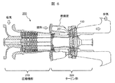
- FIG. 6 is a schematic cross-sectional view showing an example of a gas turbine equipped with the Co-based alloy product according to the present invention.
- the gas turbine 200 is roughly composed of a compressor unit 210 that compresses intake air and a turbine unit 220 that blows combustion gas of fuel to turbine blades to obtain rotational power.
- the high temperature member of the present invention can be suitably used as the turbine nozzle 221 in the turbine section 220 or the turbine vane 100.
- the high temperature member of the present invention is not limited to gas turbine applications, but may be used for other turbine applications (for example, steam turbine applications), and may be used under high temperature environments in other machines/apparatuses. It may be a member.
- FIG. 7 is an example of a Co-based alloy product according to the present invention, and is a schematic perspective view showing a heat exchanger as a high temperature member.
- the heat exchanger 300 shown in FIG. 7 is an example of a plate fin type heat exchanger, and basically has a structure in which separate layers 301 and fin layers 302 are alternately laminated. Both ends of the fin layer 302 in the flow channel width direction are sealed by side bar portions 303. By alternately circulating the high temperature fluid and the low temperature fluid through the adjacent fin layers 302, heat exchange is performed between the high temperature fluid and the low temperature fluid.
- the heat exchanger 300 according to the present invention is integrally formed without brazing or welding the components of the conventional heat exchanger (for example, the separate plate, the corrugated fin, the side bar), It can be made more heat resistant and lighter than a heat exchanger. Further, by forming an appropriate uneven shape on the surface of the flow path, the fluid can be turbulent and the heat transfer efficiency can be improved. Improvement of heat transfer efficiency leads to miniaturization of the heat exchanger.
- alloy powder preparation step S1 Preparation of alloy powder IA-1 to IA-7 and CA-1 to CA-5) Co-based alloy powders having the chemical compositions shown in Table 1 were prepared (alloy powder preparation step S1). Specifically, first, after mixing the raw materials, a master alloy ingot production step S1a for producing a master alloy ingot (mass: about 2 kg) by melting and casting by a vacuum high frequency induction melting method was performed. Next, an atomizing element step S1b of remelting the mother alloy ingot and forming an alloy powder by a gas atomizing method in an argon gas atmosphere was performed.
- an alloy powder classifying step S1c for controlling the particle size of the alloy powder was performed to classify the powder particle size to the range of 5 to 25 ⁇ m.
- the invention alloy powders IA-1 to IA-7 are alloy powders having a chemical composition satisfying the provisions of the present invention.
- the comparative alloy powder CA-1 has a C content and a Cr content outside the provisions of the present invention.
- the C content rate, the Ni content rate, and the total content rate of “Ti+Zr+Hf+V+Nb+Ta” are out of the regulation of the present invention.
- the C content rate, the N content rate, and the total content rate of “Ti+Zr+Hf+V+Nb+Ta” are out of the regulation of the present invention.
- the total content of “Ti+Zr+Hf+V+Nb+Ta” is outside the regulation of the present invention.
- the W content and the total content of “Ti+Zr+Hf+V+Nb+Ta” are out of the regulation of the present invention.
- Example 2 (Examination of SLM conditions in the selective laser melting process) An AM body (diameter 8 mm x length 10 mm) was formed by the SLM method using the IA-4 alloy powder prepared in Experiment 1 (selective laser melting step S2).
- the control of the local heat input amount corresponds to the control of the cooling rate.
- the average size of the segregated cells was measured by observing the microstructure of each AM body prepared above. The microstructure was observed by SEM. The average size of the segregation cells was measured on the obtained SEM observation image by image analysis using image processing software (ImageJ, public domain software developed by National Institutes of Health (NIH) in the United States).
- FIG. 8 is an example of SLM conditions in the selective laser melting step S2, and is a graph showing the relationship between the thickness of the alloy powder bed and the local heat input.
- FIG. 8 as a result of observing the microstructure of the formed AM body, those having an average size of segregated cells in the range of 0.15 to 1.5 ⁇ m were judged as “passed” and indicated by “ ⁇ ” in the figure, and other than that. Those were judged to be "failed” and indicated by "x” in the figure.
- the SLM conditions in the selective laser melting step S2 are as follows: the thickness h of the alloy powder bed (unit: ⁇ m), the laser light output P (unit: W), and the laser light scanning speed S (unit: It is confirmed that it is preferable to control so that the relationship with (mm/s) satisfies “15 ⁇ h ⁇ 150” and “67(P/S)-3.5 ⁇ h ⁇ 2222(P/S)+13”. .. That is, the hatched area is the area for acceptance determination.
- Example 3 (Examination of heat treatment conditions in the first heat treatment step) An AM body (diameter 10 mm x length 50 mm) was formed by the SLM method using the IA-5 and IA-6 alloy powders prepared in Experiment 1 (selective laser melting step S2).
- Each AM body prepared above was heat-treated at 950 to 1250 ° C. for 2 to 4 hours (first heat treatment step S3).
- each AM body subjected to the first heat treatment is subjected to a heat treatment of holding at 900° C. for 4 hours (second heat treatment step S4), and a Co-based alloy using IA-5 powder and IA-6 powder.
- Products IAP-5a to IAP-5d, IAP-6a to IAP-6d
- Test pieces for mechanical property testing were collected from each of the produced alloy products and subjected to mechanical property testing.
- a creep test was performed under conditions of a temperature of 850°C and a stress of 168 MPa, and the creep rupture time was measured. From the required characteristics of the high temperature member targeted by the present invention, a creep rupture time of 1200 hours or more was determined as "pass”, and a creep rupture time of less than 1200 hours was determined as "fail". It can be said that this creep characteristic is equivalent to that of the Ni-based alloy material.
- Each AM body prepared above was heat-treated at 1000 ° C. for 4 hours (first heat treatment step S3).
- each AM body subjected to the first heat treatment is subjected to a heat treatment of holding at 850° C. for 1 hour (second heat treatment step S4) to produce a Co-based alloy using IA-1 to IA-7 powders.
- Products IAP-1-1 to IAP-7-1, and Co-based alloy products CAP-1-1 to CAP-5-1 using powders CA-1 to CA-5 were produced.
- Microstructure observation and mechanical property test From the Co-based alloy products IAP-1-1 to IAP-7-1 and CAP-1-1 to CAP-5-1 produced above, sample pieces for microstructural observation and mechanical property test were collected. Then, microstructure observation and mechanical property test were performed.
- IA-1 to IA-7 having the chemical composition specified in the present invention are preferable as the starting powder of the Co-based alloy product. Further, by dispersing and precipitating the precipitated strengthened carbide phase particles in the matrix crystal grains at an average interparticle distance of 0.15 to 1.5 ⁇ m and precipitating the grain boundary strengthened carbide phase particles on the grain boundaries of the matrix, Co It was confirmed that the creep characteristics of the base alloy product could be improved.
- Turbine stationary blade 101... Inner ring side end wall, 102... Blade section, 103... Outer ring side end wall, 200... Gas turbine, 210... Compressor section, 220... Turbine section, 221... Turbine nozzle, 300... Heat exchange Container, 301... Separate layer, 302... Fin layer, 303... Sidebar part.
Landscapes
- Engineering & Computer Science (AREA)
- Chemical & Material Sciences (AREA)
- Materials Engineering (AREA)
- Manufacturing & Machinery (AREA)
- Mechanical Engineering (AREA)
- Physics & Mathematics (AREA)
- Organic Chemistry (AREA)
- Metallurgy (AREA)
- Thermal Sciences (AREA)
- General Engineering & Computer Science (AREA)
- Automation & Control Theory (AREA)
- Nanotechnology (AREA)
- Plasma & Fusion (AREA)
- Crystallography & Structural Chemistry (AREA)
- Powder Metallurgy (AREA)
Priority Applications (7)
| Application Number | Priority Date | Filing Date | Title |
|---|---|---|---|
| KR1020217002586A KR102422684B1 (ko) | 2019-03-07 | 2019-03-07 | 코발트기 합금 제조물, 해당 제조물의 제조 방법, 및 코발트기 합금 물품 |
| CN201980003000.8A CN112004952B (zh) | 2019-03-07 | 2019-03-07 | 钴基合金制造物的制造方法 |
| EP19812654.2A EP3733886B1 (de) | 2019-03-07 | 2019-03-07 | Produkt mit kobaltbasierter legierung, verfahren zur herstellung des besagten produkts und artikel mit kobaltbasierter legierung |
| JP2020509122A JP6935579B2 (ja) | 2019-03-07 | 2019-03-07 | コバルト基合金製造物および該製造物の製造方法 |
| PCT/JP2019/009205 WO2020179080A1 (ja) | 2019-03-07 | 2019-03-07 | コバルト基合金製造物、該製造物の製造方法、およびコバルト基合金物品 |
| SG11202012572PA SG11202012572PA (en) | 2019-03-07 | 2019-03-07 | Cobalt based alloy product, method for manufacturing same, and cobalt based alloy article |
| US16/620,719 US11414728B2 (en) | 2019-03-07 | 2019-03-07 | Cobalt based alloy product, method for manufacturing same, and cobalt based alloy article |
Applications Claiming Priority (1)
| Application Number | Priority Date | Filing Date | Title |
|---|---|---|---|
| PCT/JP2019/009205 WO2020179080A1 (ja) | 2019-03-07 | 2019-03-07 | コバルト基合金製造物、該製造物の製造方法、およびコバルト基合金物品 |
Publications (1)
| Publication Number | Publication Date |
|---|---|
| WO2020179080A1 true WO2020179080A1 (ja) | 2020-09-10 |
Family
ID=72337760
Family Applications (1)
| Application Number | Title | Priority Date | Filing Date |
|---|---|---|---|
| PCT/JP2019/009205 Ceased WO2020179080A1 (ja) | 2019-03-07 | 2019-03-07 | コバルト基合金製造物、該製造物の製造方法、およびコバルト基合金物品 |
Country Status (7)
| Country | Link |
|---|---|
| US (1) | US11414728B2 (de) |
| EP (1) | EP3733886B1 (de) |
| JP (1) | JP6935579B2 (de) |
| KR (1) | KR102422684B1 (de) |
| CN (1) | CN112004952B (de) |
| SG (1) | SG11202012572PA (de) |
| WO (1) | WO2020179080A1 (de) |
Cited By (7)
| Publication number | Priority date | Publication date | Assignee | Title |
|---|---|---|---|---|
| JPWO2020179084A1 (ja) * | 2019-03-07 | 2021-03-11 | 三菱パワー株式会社 | コバルト基合金製造物、およびコバルト基合金物品 |
| US11306372B2 (en) | 2019-03-07 | 2022-04-19 | Mitsubishi Power, Ltd. | Cobalt-based alloy powder, cobalt-based alloy sintered body, and method for producing cobalt-based alloy sintered body |
| US11325189B2 (en) | 2017-09-08 | 2022-05-10 | Mitsubishi Heavy Industries, Ltd. | Cobalt based alloy additive manufactured article, cobalt based alloy product, and method for manufacturing same |
| US11414728B2 (en) | 2019-03-07 | 2022-08-16 | Mitsubishi Heavy Industries, Ltd. | Cobalt based alloy product, method for manufacturing same, and cobalt based alloy article |
| US11427893B2 (en) | 2019-03-07 | 2022-08-30 | Mitsubishi Heavy Industries, Ltd. | Heat exchanger |
| US11499208B2 (en) | 2019-03-07 | 2022-11-15 | Mitsubishi Heavy Industries, Ltd. | Cobalt based alloy product |
| US11613795B2 (en) | 2019-03-07 | 2023-03-28 | Mitsubishi Heavy Industries, Ltd. | Cobalt based alloy product and method for manufacturing same |
Families Citing this family (6)
| Publication number | Priority date | Publication date | Assignee | Title |
|---|---|---|---|---|
| CA3095046A1 (en) | 2018-03-29 | 2019-10-03 | Oerlikon Metco (Us) Inc. | Reduced carbides ferrous alloys |
| JP7076581B2 (ja) * | 2019-12-26 | 2022-05-27 | 三菱重工業株式会社 | コバルト基合金製造物 |
| US20220220585A1 (en) * | 2020-09-04 | 2022-07-14 | Mitsubishi Heavy Industries, Ltd. | Cobalt based alloy material and cobalt based alloy product |
| DE112020007281T5 (de) * | 2020-12-28 | 2023-04-13 | Mitsubishi Heavy Industries Engine & Turbocharger, Ltd. | Düsenkomponente, variabler düsenmechanismus eines turboladers mit variabler geometrie, turbolader mit variabler geometrie und verfahren zur herstellung einer düsenkomponente |
| JP7324254B2 (ja) | 2021-09-01 | 2023-08-09 | 三菱重工業株式会社 | Co基合金材料、Co基合金製造物、および該製造物の製造方法 |
| US12195828B2 (en) | 2021-09-30 | 2025-01-14 | Daido Steel Co., Ltd. | Cobalt-based alloy product and method for producing cobalt-based alloy product |
Citations (9)
| Publication number | Priority date | Publication date | Assignee | Title |
|---|---|---|---|---|
| JPS61243143A (ja) | 1984-11-06 | 1986-10-29 | Agency Of Ind Science & Technol | Co基超塑性合金およびその製造方法 |
| JPH07179967A (ja) | 1993-12-24 | 1995-07-18 | Kubota Corp | 耐食性、耐摩耗性及び高温強度にすぐれるコバルト基合金 |
| JPH09157780A (ja) * | 1995-12-05 | 1997-06-17 | Hitachi Ltd | 高耐食性Co基合金 |
| JP2016102229A (ja) * | 2014-11-27 | 2016-06-02 | 山陽特殊製鋼株式会社 | 造形用金属粉末 |
| JP2016535169A (ja) | 2013-08-20 | 2016-11-10 | ザ・トラスティーズ・オブ・プリンストン・ユニバーシティThe Trustees Of Princeton University | 密度向上法及び組成物 |
| JP2017186620A (ja) * | 2016-04-06 | 2017-10-12 | セイコーエプソン株式会社 | 粉末冶金用金属粉末、コンパウンド、造粒粉末、焼結体および耐熱部品 |
| CN107513642A (zh) * | 2017-10-17 | 2017-12-26 | 广州纳联材料科技有限公司 | 钴基合金粉末及其制备方法和应用 |
| WO2019031577A1 (ja) * | 2017-08-09 | 2019-02-14 | 日立金属株式会社 | 合金部材、該合金部材の製造方法、および該合金部材を用いた製造物 |
| JP2019049022A (ja) * | 2017-09-08 | 2019-03-28 | 三菱日立パワーシステムズ株式会社 | コバルト基合金積層造形体、コバルト基合金製造物、およびそれらの製造方法 |
Family Cites Families (45)
| Publication number | Priority date | Publication date | Assignee | Title |
|---|---|---|---|---|
| JPS5018315A (de) | 1973-05-30 | 1975-02-26 | ||
| JPS5576038A (en) * | 1978-12-04 | 1980-06-07 | Hitachi Ltd | High strength high toughness cobalt-base alloy |
| JPS5842741A (ja) | 1981-09-07 | 1983-03-12 | Res Inst Electric Magnetic Alloys | 磁気記録再生ヘツド用耐摩耗性高透磁率合金およびその製造法ならびに磁気記録再生ヘツド |
| JPS58117848A (ja) | 1982-01-06 | 1983-07-13 | Mitsubishi Metal Corp | 燃焼雰囲気ですぐれた高温耐食性および高温耐酸化性を示す高強度ni基鋳造合金 |
| JPS6311638A (ja) | 1986-03-20 | 1988-01-19 | Hitachi Ltd | 高強度高靭性コバルト基合金及びその製造法 |
| EP0433072B1 (de) | 1989-12-15 | 1994-11-09 | Inco Alloys International, Inc. | Oxidationsbeständige Legierungen mit niedrigem Ausdehnungskoeffizient |
| JPH06287667A (ja) | 1993-04-02 | 1994-10-11 | Toshiba Corp | 耐熱鋳造Co基合金 |
| WO1997010368A1 (fr) | 1995-09-11 | 1997-03-20 | Hitachi, Ltd. | Alliage a base de cobalt, buse de turbine a gaz et materiau de soudure fabriques avec cet alliage |
| US5640667A (en) | 1995-11-27 | 1997-06-17 | Board Of Regents, The University Of Texas System | Laser-directed fabrication of full-density metal articles using hot isostatic processing |
| JP2002249838A (ja) | 1996-04-09 | 2002-09-06 | Mitsubishi Heavy Ind Ltd | 化石燃料燃焼装置用耐食耐熱Ni基合金 |
| FR2769024A1 (fr) * | 1997-09-29 | 1999-04-02 | Saint Gobain Isover | Alliage a base de cobalt, article realise a partir de l'alliage et son procede de fabrication |
| FR2809387B1 (fr) | 2000-05-23 | 2002-12-20 | Saint Gobain Isover | Procede de fabrication de laine minerale, alliages a base de cobalt pour le procede et autres utilisations |
| JP4264926B2 (ja) | 2002-07-05 | 2009-05-20 | 日本発條株式会社 | 析出強化型Co−Ni基耐熱合金の製造方法 |
| JP3842717B2 (ja) | 2002-10-16 | 2006-11-08 | 株式会社日立製作所 | 溶接材料、溶接構造物、ガスタービン動翼及びガスタービン動翼又は静翼の補修方法 |
| US7067201B2 (en) | 2003-09-29 | 2006-06-27 | Vetco Gray Inc. | Wear resistant coating for keel joint |
| JP4542857B2 (ja) | 2004-09-22 | 2010-09-15 | 財団法人ファインセラミックスセンター | 耐酸化性ユニット及び耐酸化性を付与する方法 |
| JP4996468B2 (ja) | 2005-09-15 | 2012-08-08 | 独立行政法人科学技術振興機構 | 高耐熱性,高強度Co基合金及びその製造方法 |
| EP1914327A1 (de) | 2006-10-17 | 2008-04-23 | Siemens Aktiengesellschaft | Nickel-Basis-Superlegierung |
| JP5201334B2 (ja) | 2008-03-19 | 2013-06-05 | 大同特殊鋼株式会社 | Co基合金 |
| JP5696995B2 (ja) | 2009-11-19 | 2015-04-08 | 独立行政法人物質・材料研究機構 | 耐熱超合金 |
| JP5582532B2 (ja) | 2010-08-23 | 2014-09-03 | 大同特殊鋼株式会社 | Co基合金 |
| CH705750A1 (de) | 2011-10-31 | 2013-05-15 | Alstom Technology Ltd | Verfahren zur Herstellung von Komponenten oder Abschnitten, die aus einer Hochtemperatur-Superlegierung bestehen. |
| EP2790858B1 (de) | 2011-12-14 | 2017-02-08 | General Electric Technology GmbH | Verfahren zur generativen herstellung eines artikels aus schwer zu schweissendem material |
| US9346101B2 (en) | 2013-03-15 | 2016-05-24 | Kennametal Inc. | Cladded articles and methods of making the same |
| US9482249B2 (en) | 2013-09-09 | 2016-11-01 | General Electric Company | Three-dimensional printing process, swirling device and thermal management process |
| CN103981380B (zh) * | 2014-05-29 | 2016-01-27 | 大连理工大学 | 一种钴基高温合金的制备方法 |
| EP3025809B1 (de) | 2014-11-28 | 2017-11-08 | Ansaldo Energia IP UK Limited | Verfahren zur herstellung einer komponente mittels additivem fertigungsverfahren |
| US10099290B2 (en) | 2014-12-18 | 2018-10-16 | General Electric Company | Hybrid additive manufacturing methods using hybrid additively manufactured features for hybrid components |
| JP6358246B2 (ja) | 2015-01-08 | 2018-07-18 | セイコーエプソン株式会社 | 粉末冶金用金属粉末、コンパウンド、造粒粉末、焼結体および装飾品 |
| US11434766B2 (en) | 2015-03-05 | 2022-09-06 | General Electric Company | Process for producing a near net shape component with consolidation of a metallic powder |
| JP6311638B2 (ja) | 2015-04-07 | 2018-04-18 | 京セラドキュメントソリューションズ株式会社 | ヒンジ構造及びこれを備えた画像形成装置 |
| MX2015016373A (es) * | 2015-11-27 | 2017-05-26 | Geodent S A De C V | Aleacion de base cobalto anticorrosion para restauraciones dentales. |
| JP6372498B2 (ja) | 2016-02-19 | 2018-08-15 | セイコーエプソン株式会社 | 粉末冶金用金属粉末、コンパウンド、造粒粉末、焼結体および耐熱部品 |
| JP6931545B2 (ja) | 2017-03-29 | 2021-09-08 | 三菱重工業株式会社 | Ni基合金積層造形体の熱処理方法、Ni基合金積層造形体の製造方法、積層造形体用Ni基合金粉末、およびNi基合金積層造形体 |
| AU2018422117B2 (en) | 2018-12-10 | 2021-06-03 | Mitsubishi Power, Ltd. | Cobalt based alloy additive manufactured article, cobalt based alloy product, and method for manufacturing same |
| US11414728B2 (en) | 2019-03-07 | 2022-08-16 | Mitsubishi Heavy Industries, Ltd. | Cobalt based alloy product, method for manufacturing same, and cobalt based alloy article |
| WO2020179084A1 (ja) | 2019-03-07 | 2020-09-10 | 三菱日立パワーシステムズ株式会社 | コバルト基合金製造物、およびコバルト基合金物品 |
| SG11202012575WA (en) | 2019-03-07 | 2021-09-29 | Mitsubishi Power Ltd | Cobalt based alloy product |
| EP3733885A4 (de) | 2019-03-07 | 2020-12-30 | Mitsubishi Power, Ltd. | Wärmetauscher |
| EP3725902B1 (de) | 2019-03-07 | 2023-03-01 | Mitsubishi Heavy Industries, Ltd. | Produkt aus einer legierung auf kobaltbasis und verfahren zu seiner herstellung |
| JP6924874B2 (ja) | 2019-04-02 | 2021-08-25 | 三菱パワー株式会社 | コバルト基合金材料 |
| JP6713071B2 (ja) | 2019-04-02 | 2020-06-24 | 三菱日立パワーシステムズ株式会社 | コバルト基合金積層造形体の製造方法 |
| CN114222934B (zh) | 2019-08-20 | 2025-08-12 | 日本电气株式会社 | 地震观测设备、地震观测方法以及记录介质 |
| JP7274584B2 (ja) | 2019-08-21 | 2023-05-16 | 京セラ株式会社 | ハンドオーバ制御方法、中継装置、及びドナー装置 |
| JP7076581B2 (ja) | 2019-12-26 | 2022-05-27 | 三菱重工業株式会社 | コバルト基合金製造物 |
-
2019
- 2019-03-07 US US16/620,719 patent/US11414728B2/en active Active
- 2019-03-07 CN CN201980003000.8A patent/CN112004952B/zh not_active Expired - Fee Related
- 2019-03-07 SG SG11202012572PA patent/SG11202012572PA/en unknown
- 2019-03-07 KR KR1020217002586A patent/KR102422684B1/ko not_active Expired - Fee Related
- 2019-03-07 JP JP2020509122A patent/JP6935579B2/ja not_active Expired - Fee Related
- 2019-03-07 WO PCT/JP2019/009205 patent/WO2020179080A1/ja not_active Ceased
- 2019-03-07 EP EP19812654.2A patent/EP3733886B1/de active Active
Patent Citations (9)
| Publication number | Priority date | Publication date | Assignee | Title |
|---|---|---|---|---|
| JPS61243143A (ja) | 1984-11-06 | 1986-10-29 | Agency Of Ind Science & Technol | Co基超塑性合金およびその製造方法 |
| JPH07179967A (ja) | 1993-12-24 | 1995-07-18 | Kubota Corp | 耐食性、耐摩耗性及び高温強度にすぐれるコバルト基合金 |
| JPH09157780A (ja) * | 1995-12-05 | 1997-06-17 | Hitachi Ltd | 高耐食性Co基合金 |
| JP2016535169A (ja) | 2013-08-20 | 2016-11-10 | ザ・トラスティーズ・オブ・プリンストン・ユニバーシティThe Trustees Of Princeton University | 密度向上法及び組成物 |
| JP2016102229A (ja) * | 2014-11-27 | 2016-06-02 | 山陽特殊製鋼株式会社 | 造形用金属粉末 |
| JP2017186620A (ja) * | 2016-04-06 | 2017-10-12 | セイコーエプソン株式会社 | 粉末冶金用金属粉末、コンパウンド、造粒粉末、焼結体および耐熱部品 |
| WO2019031577A1 (ja) * | 2017-08-09 | 2019-02-14 | 日立金属株式会社 | 合金部材、該合金部材の製造方法、および該合金部材を用いた製造物 |
| JP2019049022A (ja) * | 2017-09-08 | 2019-03-28 | 三菱日立パワーシステムズ株式会社 | コバルト基合金積層造形体、コバルト基合金製造物、およびそれらの製造方法 |
| CN107513642A (zh) * | 2017-10-17 | 2017-12-26 | 广州纳联材料科技有限公司 | 钴基合金粉末及其制备方法和应用 |
Non-Patent Citations (1)
| Title |
|---|
| See also references of EP3733886A4 |
Cited By (7)
| Publication number | Priority date | Publication date | Assignee | Title |
|---|---|---|---|---|
| US11325189B2 (en) | 2017-09-08 | 2022-05-10 | Mitsubishi Heavy Industries, Ltd. | Cobalt based alloy additive manufactured article, cobalt based alloy product, and method for manufacturing same |
| JPWO2020179084A1 (ja) * | 2019-03-07 | 2021-03-11 | 三菱パワー株式会社 | コバルト基合金製造物、およびコバルト基合金物品 |
| US11306372B2 (en) | 2019-03-07 | 2022-04-19 | Mitsubishi Power, Ltd. | Cobalt-based alloy powder, cobalt-based alloy sintered body, and method for producing cobalt-based alloy sintered body |
| US11414728B2 (en) | 2019-03-07 | 2022-08-16 | Mitsubishi Heavy Industries, Ltd. | Cobalt based alloy product, method for manufacturing same, and cobalt based alloy article |
| US11427893B2 (en) | 2019-03-07 | 2022-08-30 | Mitsubishi Heavy Industries, Ltd. | Heat exchanger |
| US11499208B2 (en) | 2019-03-07 | 2022-11-15 | Mitsubishi Heavy Industries, Ltd. | Cobalt based alloy product |
| US11613795B2 (en) | 2019-03-07 | 2023-03-28 | Mitsubishi Heavy Industries, Ltd. | Cobalt based alloy product and method for manufacturing same |
Also Published As
| Publication number | Publication date |
|---|---|
| JPWO2020179080A1 (ja) | 2021-04-30 |
| CN112004952A (zh) | 2020-11-27 |
| KR20210024121A (ko) | 2021-03-04 |
| US20210340645A1 (en) | 2021-11-04 |
| EP3733886A1 (de) | 2020-11-04 |
| SG11202012572PA (en) | 2021-09-29 |
| CN112004952B (zh) | 2022-05-13 |
| EP3733886A4 (de) | 2021-09-22 |
| KR102422684B1 (ko) | 2022-07-20 |
| JP6935579B2 (ja) | 2021-09-15 |
| US11414728B2 (en) | 2022-08-16 |
| EP3733886B1 (de) | 2022-08-24 |
Similar Documents
| Publication | Publication Date | Title |
|---|---|---|
| KR102225271B1 (ko) | 코발트기 합금 재료 | |
| JP6935580B2 (ja) | コバルト基合金製造物およびその製造方法 | |
| JP6935579B2 (ja) | コバルト基合金製造物および該製造物の製造方法 | |
| JP6935578B2 (ja) | コバルト基合金製造物 | |
| JP6713071B2 (ja) | コバルト基合金積層造形体の製造方法 | |
| JP7076581B2 (ja) | コバルト基合金製造物 | |
| JP6935577B2 (ja) | コバルト基合金製造物 | |
| JP6994564B2 (ja) | 熱交換器 | |
| WO2020121367A1 (ja) | コバルト基合金積層造形体、コバルト基合金製造物、およびそれらの製造方法 | |
| JP6924874B2 (ja) | コバルト基合金材料 | |
| JP2023105829A (ja) | コバルト基合金材料およびコバルト基合金製造物 |
Legal Events
| Date | Code | Title | Description |
|---|---|---|---|
| ENP | Entry into the national phase |
Ref document number: 2020509122 Country of ref document: JP Kind code of ref document: A |
|
| ENP | Entry into the national phase |
Ref document number: 2019812654 Country of ref document: EP Effective date: 20191209 |
|
| ENP | Entry into the national phase |
Ref document number: 20217002586 Country of ref document: KR Kind code of ref document: A |
|
| NENP | Non-entry into the national phase |
Ref country code: DE |