WO2020179162A1 - Dispositif de séparation et de fixation, machine de traitement et tête de traitement - Google Patents
Dispositif de séparation et de fixation, machine de traitement et tête de traitement Download PDFInfo
- Publication number
- WO2020179162A1 WO2020179162A1 PCT/JP2019/047419 JP2019047419W WO2020179162A1 WO 2020179162 A1 WO2020179162 A1 WO 2020179162A1 JP 2019047419 W JP2019047419 W JP 2019047419W WO 2020179162 A1 WO2020179162 A1 WO 2020179162A1
- Authority
- WO
- WIPO (PCT)
- Prior art keywords
- mounting plate
- hole
- connecting member
- attachment
- protrusion
- Prior art date
- Legal status (The legal status is an assumption and is not a legal conclusion. Google has not performed a legal analysis and makes no representation as to the accuracy of the status listed.)
- Ceased
Links
Images
















Classifications
-
- B—PERFORMING OPERATIONS; TRANSPORTING
- B23—MACHINE TOOLS; METAL-WORKING NOT OTHERWISE PROVIDED FOR
- B23K—SOLDERING OR UNSOLDERING; WELDING; CLADDING OR PLATING BY SOLDERING OR WELDING; CUTTING BY APPLYING HEAT LOCALLY, e.g. FLAME CUTTING; WORKING BY LASER BEAM
- B23K26/00—Working by laser beam, e.g. welding, cutting or boring
- B23K26/02—Positioning or observing the workpiece, e.g. with respect to the point of impact; Aligning, aiming or focusing the laser beam
- B23K26/06—Shaping the laser beam, e.g. by masks or multi-focusing
- B23K26/0665—Shaping the laser beam, e.g. by masks or multi-focusing by beam condensation on the workpiece, e.g. for focusing
-
- B—PERFORMING OPERATIONS; TRANSPORTING
- B23—MACHINE TOOLS; METAL-WORKING NOT OTHERWISE PROVIDED FOR
- B23K—SOLDERING OR UNSOLDERING; WELDING; CLADDING OR PLATING BY SOLDERING OR WELDING; CUTTING BY APPLYING HEAT LOCALLY, e.g. FLAME CUTTING; WORKING BY LASER BEAM
- B23K37/00—Auxiliary devices or processes, not specially adapted for a procedure covered by only one of the other main groups of this subclass
- B23K37/02—Carriages for supporting the welding or cutting element
- B23K37/0241—Attachments between the welding or cutting element and the carriage
-
- B—PERFORMING OPERATIONS; TRANSPORTING
- B23—MACHINE TOOLS; METAL-WORKING NOT OTHERWISE PROVIDED FOR
- B23K—SOLDERING OR UNSOLDERING; WELDING; CLADDING OR PLATING BY SOLDERING OR WELDING; CUTTING BY APPLYING HEAT LOCALLY, e.g. FLAME CUTTING; WORKING BY LASER BEAM
- B23K26/00—Working by laser beam, e.g. welding, cutting or boring
- B23K26/36—Removing material
- B23K26/38—Removing material by boring or cutting
-
- B—PERFORMING OPERATIONS; TRANSPORTING
- B23—MACHINE TOOLS; METAL-WORKING NOT OTHERWISE PROVIDED FOR
- B23K—SOLDERING OR UNSOLDERING; WELDING; CLADDING OR PLATING BY SOLDERING OR WELDING; CUTTING BY APPLYING HEAT LOCALLY, e.g. FLAME CUTTING; WORKING BY LASER BEAM
- B23K37/00—Auxiliary devices or processes, not specially adapted for a procedure covered by only one of the other main groups of this subclass
- B23K37/006—Safety devices for welding or cutting
-
- B—PERFORMING OPERATIONS; TRANSPORTING
- B23—MACHINE TOOLS; METAL-WORKING NOT OTHERWISE PROVIDED FOR
- B23Q—DETAILS, COMPONENTS, OR ACCESSORIES FOR MACHINE TOOLS, e.g. ARRANGEMENTS FOR COPYING OR CONTROLLING; MACHINE TOOLS IN GENERAL CHARACTERISED BY THE CONSTRUCTION OF PARTICULAR DETAILS OR COMPONENTS; COMBINATIONS OR ASSOCIATIONS OF METAL-WORKING MACHINES, NOT DIRECTED TO A PARTICULAR RESULT
- B23Q3/00—Devices holding, supporting, or positioning work or tools, of a kind normally removable from the machine
- B23Q3/02—Devices holding, supporting, or positioning work or tools, of a kind normally removable from the machine for mounting on a work-table, tool-slide, or analogous part
-
- B—PERFORMING OPERATIONS; TRANSPORTING
- B23—MACHINE TOOLS; METAL-WORKING NOT OTHERWISE PROVIDED FOR
- B23Q—DETAILS, COMPONENTS, OR ACCESSORIES FOR MACHINE TOOLS, e.g. ARRANGEMENTS FOR COPYING OR CONTROLLING; MACHINE TOOLS IN GENERAL CHARACTERISED BY THE CONSTRUCTION OF PARTICULAR DETAILS OR COMPONENTS; COMBINATIONS OR ASSOCIATIONS OF METAL-WORKING MACHINES, NOT DIRECTED TO A PARTICULAR RESULT
- B23Q3/00—Devices holding, supporting, or positioning work or tools, of a kind normally removable from the machine
- B23Q3/15—Devices for holding work using magnetic or electric force acting directly on the work
-
- B—PERFORMING OPERATIONS; TRANSPORTING
- B23—MACHINE TOOLS; METAL-WORKING NOT OTHERWISE PROVIDED FOR
- B23Q—DETAILS, COMPONENTS, OR ACCESSORIES FOR MACHINE TOOLS, e.g. ARRANGEMENTS FOR COPYING OR CONTROLLING; MACHINE TOOLS IN GENERAL CHARACTERISED BY THE CONSTRUCTION OF PARTICULAR DETAILS OR COMPONENTS; COMBINATIONS OR ASSOCIATIONS OF METAL-WORKING MACHINES, NOT DIRECTED TO A PARTICULAR RESULT
- B23Q3/00—Devices holding, supporting, or positioning work or tools, of a kind normally removable from the machine
- B23Q3/18—Devices holding, supporting, or positioning work or tools, of a kind normally removable from the machine for positioning only
Definitions
- the present invention relates to a desorption device equipped with a suction means, a processing machine and a processing head equipped with this desorption device.
- a machining head and a moving means for moving the machining head in two or three dimensions are provided, and the machining head is moved relative to the work to be machined by a preset locus by the moving means.
- a processing machine that performs the processing of.
- a material is sent from a processing head, and the material is made to collide with a work for processing.
- a laser processing machine equipped with a laser processing head a plasma processing machine equipped with a plasma processing head, a water jet processing machine equipped with a water jet processing head, a gas cutting processing machine equipped with a gas processing head,
- a milling machine equipped with an abrasive spray head is provided with an abrasive spray head.
- the processing head when the work is warped, the processing head may collide with the warped portion of the work, and the processing head may be damaged by the impact force at the time of the collision. Further, the processing head may collide with an obstacle such as a workpiece and be damaged due to an operator's erroneous operation or a failure of the processing machine.
- Patent Document 1 discloses a detachable device including a plate fixed to a moving means and a holder connected to the plate. A processing head is fixed to the holder. A magnet that attracts the other connecting surface is provided on either one of the connecting surface of the plate connected to the holder and the connecting surface of the holder connected to the plate. A plurality of spheres protruding toward the other is formed on one of the connection surfaces of the plate and the connection surface of the holder, and a plurality of concave surfaces into which the spheres are fitted are formed on the other connection surface. There is.
- the sphere and the concave surface are misaligned due to a manufacturing error, so the sphere and the concave surface are only one-sided, and the plate and the holder are misaligned.
- the present invention has been made in view of the above, and an object of the present invention is to obtain a detachable device having high positioning accuracy at the time of connecting the first mounting plate and the second mounting plate.
- a desorption device includes a first attachment plate to which a first attachment object is attached, a second attachment object, and a first attachment plate.
- a second mounting plate arranged with a space between them, a suction means for detachably connecting the first mounting plate and the second mounting plate, and a second mounting plate disposed between the first mounting plate and the second mounting plate.
- the first mounting plate and the second mounting plate, and a connecting member formed separately.
- the connecting member is fixed to the first mounting plate.
- a protrusion protruding toward the other is formed on either one of the connecting member and the second mounting plate.
- a hole into which the protrusion fits is formed in the other of the connecting member and the second mounting plate.
- a first contact surface in the form of a rotating surface is formed on the protrusion.
- a second contact surface having a rotating surface is formed on the inner surface of the hole. The first contact surface and the second contact surface come into contact with each other in a state where the central axis of the protrusion and the central axis of the hole coincide with each other.
- the figure for demonstrating the attachment/detachment apparatus concerning Embodiment 1 of this invention The figure which shows the main mounting plate which concerns on Embodiment 1.
- FIG. 3 is a diagram showing the attachment/detachment device according to the first embodiment, showing a state in which a main mounting plate and an accessory mounting plate are connected.
- FIG. 3 is a view for explaining a contact state between the first contact surface of the protrusion and the second contact surface of the hole according to the first embodiment.
- the front view which shows the attachment/detachment device concerning the modification 4 of Embodiment 1.
- FIG. 1 XVI-XVI sectional view of the desorption device shown in FIG.
- the top view of the protrusion shown in FIG. FIG. 6 is a perspective view showing a protrusion according to a modified example 8 of the first embodiment.
- the top view of the protrusion shown in FIG. The side view which shows the hole concerning the modification 8 of Embodiment 1.
- Top view of the hole shown in FIG. 23 The figure for demonstrating the attachment/detachment apparatus concerning Embodiment 2 of this invention.
- FIG. 30 The figure for demonstrating the structural example of the laser processing machine concerning Embodiment 3 of this invention.
- XXXI-XXXI sectional view of the desorption device shown in FIG. 30 The figure for demonstrating the structural example of the laser processing machine which concerns on Embodiment 5 of this invention.
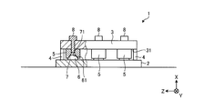
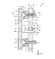
- FIG. 1 is a diagram for explaining a desorption device 1 according to a first embodiment of the present invention.
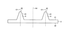
- FIG. 2 is a diagram showing the main mounting plate 2 according to the first embodiment.
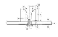
- FIG. 3 is a diagram showing the attachment plate 3 and the connecting member 5 according to the first embodiment.
- the attachment / detachment device 1 includes a main attachment plate 2, an accessory attachment plate 3, a suction means 4, and a connecting member 5.
- the left-right direction of FIG. 1 is defined as the X-axis direction
- the up-down direction of FIG. 1 is defined as the Z-axis direction
- the directions orthogonal to the X-axis direction and the Z-axis direction are defined as the Y-axis direction.
- XYZ axis coordinates shown in the drawings other than FIG. 1 correspond to the XYZ axis coordinate system shown in FIG.
- the term "orthogonal" in the specification of the present application includes not only a state of being completely orthogonal, but also a state of being slightly oblique rather than strictly orthogonal.
- the main attachment plate 2 is a plate-shaped member to which the main attachment target 9 is attached.
- the main attachment object 9 is, for example, a moving unit that moves the attached attachment object 10 in two dimensions or three dimensions.
- the material of the main mounting plate 2 is not particularly limited as long as it can be adsorbed by the adsorbing means 4, and is, for example, iron, stainless steel, silicon steel, aluminum, CFRP (Carbon Fiber Reinforced Plastic: carbon fiber reinforced plastic) and the like.
- the main mounting plate 2 has a main connecting surface 21 facing the accessory mounting plate 3 and a main mounting surface 22 facing the side opposite to the main connecting surface 21.
- the main mounting plate 2 to which the connecting member 5 is not fixed is the second mounting plate
- the main mounting target 9 is the second mounting target.
- the main connecting surface 21 is the second connecting surface and the main mounting surface 22 is the second mounting surface.
- the main connecting surface 21 is a plane orthogonal to the X-axis direction.
- a plurality of protrusions 6 projecting toward the accessory mounting plate 3 are formed on the main connecting surface 21.
- the plurality of protrusions 6 are arranged at intervals from each other.
- the shape of the protrusion 6 is a truncated cone shape whose diameter decreases toward the attachment plate 3.
- the protrusion 6 has a first contact surface 61 and a first top surface 62.
- the first contact surface 61 is formed in a conical surface shape whose diameter decreases toward the attached mounting plate 3.
- the first contact surface 61 is formed in a rotation surface shape having a central axis C1.
- the first contact surface 61 is formed in a shape that is axisymmetric with respect to the central axis C1.
- the central axis C1 is parallel to the normal direction N1 of the main connecting surface 21 of the main mounting plate 2. That is, the central axis C1 and the main connecting surface 21 of the main mounting plate 2 are orthogonal to each other.
- the first top surface 62 is continuous with the tip of the first contact surface 61.
- the first top surface 62 is a plane orthogonal to the X-axis direction.
- the main mounting surface 22 is a plane orthogonal to the X-axis direction.
- the main attachment target 9 is fixed to the main attachment surface 22.
- the accessory mounting plate 3 is a plate-shaped member to which the accessory mounting object 10 is mounted.
- the attached object 10 is, for example, a laser processing head of a laser processing machine, a plasma processing head of a plasma processing machine, a water jet processing head of a water jet processing machine, a gas processing head of a gas cutting processing machine, and abrasive grains of a milling processing machine. It is a spraying head.
- the attached mounting plate 3 is arranged at a distance from the main mounting plate 2 in the X-axis direction.
- the material of the accessory mounting plate 3 is not particularly limited as long as it can be adsorbed by the adsorbing means 4, but is, for example, iron, stainless steel, silicon steel, aluminum, CFRP or the like.
- the accessory mounting plate 3 has an accessory connecting surface 31 facing the main mounting plate 2 and an accessory mounting surface 32 facing the side opposite to the accessory connecting surface 31.
- the accessory mounting plate 3 to which the connecting member 5 is fixed is the first mounting plate
- the accessory mounting object 10 is the first mounting object.
- the accessory connection surface 31 is the first connection surface
- the accessory attachment surface 32 is the first attachment surface.
- the attached connecting surface 31 is a plane orthogonal to the X-axis direction.
- a connecting member 5 is fixed to the attached connecting surface 31.
- the attached mounting surface 32 is a plane orthogonal to the X-axis direction.
- the attached mounting object 10 is fixed to the attached mounting surface 32.
- a through hole 33 for passing the bolt 8 is formed in the accessory mounting plate 3.
- the through hole 33 penetrates from the attached mounting surface 32 to the attached connecting surface 31.
- the inner diameter of the through hole 33 is formed larger than the shaft diameter of the bolt 8.
- the suction means 4 is a means for connecting the main mounting plate 2 and the accessory mounting plate 3 in a separable manner.
- the attracting means 4 is not particularly limited as long as it has an attracting force that detachably connects the main mounting plate 2 and the accessory mounting plate 3, but is, for example, a magnet.
- the suction means 4 is arranged in close contact with the main connecting surface 21 and the auxiliary connecting surface 31.
- the suction means 4 is fixed to the accessory connecting surface 31 of the accessory mounting plate 3 in the present embodiment, but may be fixed to the main connecting surface 21 of the main mounting plate 2.
- the connecting member 5 is a member that connects the main mounting plate 2 and the accessory mounting plate 3.
- the material of the connecting member 5 is not particularly limited, and is, for example, stainless steel, aluminum, resin, or the like.
- the connecting member 5 has an facing surface 51 facing the main mounting plate 2 and a contact surface 52 facing the attached mounting plate 3.
- a hole 7 into which the protrusion 6 is fitted is formed on the facing surface 51.
- a second contact surface 71 and a bottom surface 72 are formed on the inner surface of the hole 7.
- the bottom surface 72 is a plane orthogonal to the X-axis direction.
- the second contact surface 71 is formed on a trumpet-shaped surface whose diameter increases from the bottom surface 72, which is the bottom of the hole 7, toward the opening 73.
- the second contact surface 71 is formed in a rotating surface shape having a central axis C2.
- the second contact surface 71 is formed in a shape that is axisymmetric with respect to the central axis C2.
- the central axis C2 is orthogonal to the contact surface 52, which is a plane that contacts the attached connecting surface 31.
- the contact surface 52 is parallel to the attached connecting surface 31.
- the central axis C2 is parallel to the normal direction N2 of the accessory connecting surface 31 of the accessory mounting plate 3. That is, the central axis C2 and the accessory connecting surface 31 of the accessory mounting plate 3 are orthogonal to each other.
- the entire contact surface 52 is a flat surface in the present embodiment, a part of the contact surface 52 may be a flat surface.
- a bolt hole 53 for fixing the bolt 8 is formed in the connecting member 5.
- the bolt hole 53 penetrates from the contact surface 52 to the bottom surface 72.
- the connecting member 5 is fixed to the accessory mounting plate 3 by screwing the bolt 8 passed through the through hole 33 of the accessory mounting plate 3 into the bolt hole 53. Since the inner diameter of the through hole 33 is formed to be larger than the shaft diameter of the bolt 8, when the bolt 8 is loosened, the connecting member 5 can be freely moved in the in-plane direction of the accessory connecting surface 31 of the accessory mounting plate 3. it can.
- the protrusion 6 and the hole 7 are formed so that the first contact surface 61 and the second contact surface 71 are in two-dimensional or three-dimensional contact with each other in a state where the central axes C1 and C2 are aligned with each other.
- the first contact surface 61 and the second contact surface 71 are arranged so that the first contact surface 61 and the second contact surface 71 contact each other two-dimensionally or three-dimensionally with the central axes C1 and C2 aligned. Diameter, curvature, etc. are set.
- the central axis C1 is orthogonal to the main connecting surface 21 of the main mounting plate 2
- the central axis C2 is orthogonal to the attached connecting surface 31 of the accessory mounting plate 3.
- the main connecting surface 21 of the main mounting plate 2 and the accessory connecting surface 31 of the accessory mounting plate 3 can be made to be in a strictly parallel state.
- the attachment / detachment device 1 that realizes a state in which the mounting plate pairs are accurately parallel to each other without any trouble is used in, for example, a laser processing machine
- the actual trajectory of the laser beam passing through the attachment / detachment device 1 and the design optical path match. Therefore, the beam quality does not deteriorate, and a laser processing machine capable of processing with higher quality than in the past can be realized.
- FIG. 4 is a diagram for explaining an assembly method of the attachment / detachment device 1 according to the first embodiment, and is a diagram showing a step of temporarily fixing the connecting member 5 to the attached mounting plate 3.
- 5: is a figure for demonstrating the assembling method of the attachment/detachment apparatus 1 concerning Embodiment 1, and is a figure which shows the process of adjusting the position of the protrusion 6 and the hole 7 by giving an external force to the attachment mounting plate 3.
- FIG. is there.
- FIG. 6 is a diagram for explaining an assembly method of the attachment / detachment device 1 according to the first embodiment, and is a diagram showing a step of finally fixing the connecting member 5 to the attached mounting plate 3.
- the bolt 8 is inserted into the through hole 33 of the attached mounting plate 3 and the bolt hole 53 of the connecting member 5, and the connecting member 5 is temporarily fixed to the attached mounting plate 3.
- the bolt 8 is loosened into the bolt hole 53 of the connecting member 5 so that the connecting member 5 can move in the in-plane direction of the attached mounting plate 3.
- the main mounting plate 2 is arranged with the protrusion 6 facing up
- the accessory mounting plate 3 is arranged with the hole 7 facing down
- the accessory mounting plate 3 is placed on the main mounting plate 2.
- the attachment mounting plate 3 is arranged at a position where the protrusion 6 of the main mounting plate 2 and the hole 7 of the connecting member 5 substantially overlap each other.
- the surface of the attached mounting plate 3 is subjected to an external force by applying a load to the attached mounting plate 3 from above or swinging the attached mounting plate 3 to apply an external force to the attached mounting plate 3.
- the connecting member 5 is moved inward, and the position of the hole 7 is aligned with the position of the protrusion 6.
- the central axis C1 of the protrusion 6 and the central axis C2 of the hole 7 coincide with each other, and the first contact surface 61 of the protrusion 6 and the second contact surface 71 of the hole 7 come into contact with each other.
- the bolt 8 is fully tightened to connect the attachment member 3 to the attachment member 3. 5 is permanently fixed.
- the movement of the connecting member 5 is restricted.
- the suction means 4 is fixed to the attachment connecting surface 31 of the attachment mounting plate 3, and the main mounting plate 2 and the attachment mounting plate 3 are fixed by the suction force of the suction means 4.
- the accessory mounting plate 3 may be arranged with the hole 7 facing upward, and the main mounting plate 2 with the protrusion 6 facing downward may be placed on the accessory mounting plate 3.
- FIG. 7 is a diagram showing a conventional attachment / detachment device 200, showing a state in which the plate 210 and the holder 220 are separated.
- FIG. 8 is a view showing a conventional attaching/detaching device 200, showing a state in which the plate 210 and the holder 220 are connected.
- the conventional attachment / detachment device 200 includes a plate 210 and a holder 220.
- the plate 210 and the holder 220 are arranged at intervals in the X-axis direction.
- the plate 210 is provided with a positioning pin 230 that projects toward the holder 220.
- the plate 210 is provided with a sphere body 240 that is biased toward the holder 220 by a spring 260.
- a plurality of conical concave surfaces 250 into which the positioning pins 230 or the sphere 240 are fitted are formed on the surface of the holder 220 facing the plate 210.
- the positional relationship between the sphere 240 and the concave surface 250 and the positional relationship between the positioning pin 230 and the concave surface 250 may not exactly match due to manufacturing errors. Therefore, as shown in FIG. 8, if the central axis C3 of the positioning pin 230 and the central axis C5 of one concave surface 250 are aligned, the central axis C4 of the sphere 240 and the central axis C5 of the other concave surface 250 will be displaced. , The misalignment between the plate 210 and the holder 220 occurs.
- the conventional attachment/detachment device 200 does not include means for eliminating the positional deviation between the plate 210 and the holder 220. When such a desorption device 200 is used in, for example, a laser processing machine, the trajectory of the laser light deviates from the strictly designed optical path, so that the beam quality of the laser processing machine deteriorates.
- FIG. 9 is a diagram for explaining a contact state between the sphere 240 and the concave surface 250 in the state shown in FIG.
- the sphere 240 and the concave surface 250 are in a one-sided contact state, that is, in a point contact state. Therefore, the contact position between the sphere 240 and the concave surface 250 is not uniquely determined, and when the plate 210 and the holder 220 shown in FIG. 8 are once separated and then reconnected, the plate 210 and the holder are connected before and after the separation. The positional relationship with 220 was deviated.
- FIG. 10 is a diagram showing the desorption device 1 according to the first embodiment, and is a diagram showing a state in which the main mounting plate 2 and the accessory mounting plate 3 are connected.
- FIG. 11 is a diagram for explaining a contact state between the first contact surface 61 of the protrusion 6 and the second contact surface 71 of the hole 7 according to the first embodiment.
- the through holes 33, the bolt holes 53, the bolts 8 and the like are omitted for convenience of description.
- the attachment/detachment device 1 includes a connecting member 5 that is separate from the main mounting plate 2 and the attached mounting plate 3, and the connecting member 5 in the temporarily fixed state is attached to the attached mounting plate 3. It can move in the in-plane direction.
- the relative position of the hole 7 with respect to the protrusion 6 can be adjusted by moving the connecting member 5, the central axis C1 of the protrusion 6 and the central axis C2 of the hole 7 can be easily aligned. That is, since the relative positions of the protrusions 6 and the holes 7 are adjusted after the production of the main mounting plate 2, the accessory mounting plate 3, and the connecting member 5, they are not affected by the manufacturing error.
- the central axis C1 of the protrusion 6 and the central axis C2 of the hole 7 are aligned with each other, the first contact surface 61 of the protrusion 6 and the second contact surface 71 of the hole 7 are circumferentially contacted with each other. That is, the state of line contact.
- the positional relationship between the main mounting plate 2 and the accessory mounting plate 3 shown in FIG. 10 is accurately determined. That is, in the present embodiment, it is possible to obtain the attachment / detachment device 1 having high positioning accuracy at the time of connecting the main mounting plate 2 and the accessory mounting plate 3.
- a desorption device 1 When such a desorption device 1 is used in, for example, a laser processing machine, the laser light can be passed through the optical path as designed, and a laser processing machine having high beam quality can be realized.
- the positional relationship between the main mounting plate 2 and the accessory mounting plate 3 is accurately determined, even if the main mounting plate 2 and the accessory mounting plate 3 are not brought into surface contact with each other, the main connecting surface 21 of the main mounting plate 2 and the accessory mounting plate 2 are attached.
- the accessory connection surface 31 of 3 becomes parallel as designed.
- the contact positions of the protrusions 6 and the holes 7 are uniquely determined, even if the main mounting plate 2 and the accessory mounting plate 3 are once separated and then reconnected, they are before and after the separation. Therefore, the positional relationship between the main mounting plate 2 and the accessory mounting plate 3 does not shift.
- a detaching device 1 is used in, for example, a laser processing machine, it is not necessary to readjust the installation angle of the transmission mirror every time the main mounting plate 2 and the auxiliary mounting plate 3 are connected, and the laser processing machine with high productivity is eliminated. Can be realized.
- a gap is provided between the main mounting plate 2 and the accessory mounting plate 3 without surface contact between the main mounting plate 2 and the accessory mounting plate 3. Therefore, when an impact force is applied to the detachable device 1 due to a collision with a work or the like (not shown), the attached mounting plate 3 can rotate relative to the main mounting plate 2 by utilizing the gap. As a result, the impact force can be converted into a rotational force and attenuated, so that damage to the components of the detachable device 1 can be suppressed.
- the projection 6 is formed on the main mounting plate 2 and the connecting member 5 in which the hole 7 is formed is fixed to the accessory mounting plate 3, but the present invention is not limited to this.
- holes may be formed in the main mounting plate 2 and protrusions may be formed in the connecting member 5.
- both the protrusion and the hole may be formed on the main mounting plate 2, and the connecting member 5 on which the protrusion is formed and the connecting member 5 on which the hole is formed may be fixed to the attached mounting plate 3, respectively.
- the connecting member 5 in which the protrusion, the hole, or both the protrusion and the hole are formed may be fixed to the main mounting plate 2.
- the main mounting plate 2 to which the connecting member 5 is fixed is the first mounting plate
- the main mounting object 9 is the first mounting object.
- the main connecting surface 21 is the first connecting surface
- the main mounting surface 22 is the first mounting surface.
- the accessory mounting plate 3 to which the connecting member 5 is not fixed is the second mounting plate
- the accessory mounting object 10 is the second mounting object.
- the attached connecting surface 31 is the second connecting surface
- the attached mounting surface 32 is the second mounting surface.
- holes, protrusions, or both holes and protrusions may be formed on the attached mounting plate 3 itself.
- FIG. 12 is a diagram showing an accessory mounting plate 3 and a connecting member 5 according to a first modification of the first embodiment.
- the same parts as those in the first embodiment described above are designated by the same reference numerals and the description thereof will be omitted.
- the connecting member 5 is fixed to the attached mounting plate 3 by the pressing tool 11.
- the retainer 11 is an L-shaped member that presses the connecting member 5 toward the attachment plate 3.
- the retainer 11 has a base portion 11a and a contact portion 11b.
- the base portion 11a is a portion extending from the attached connecting surface 31 toward a main mounting plate (not shown).
- a bolt hole 11c for fixing the bolt 8 is formed in the base portion 11a.
- the bolt hole 11c is open to the surface of the base portion 11a that is in contact with the attached connecting surface 31.
- the inner diameter of the bolt hole 11c is formed to be equal to the shaft diameter of the bolt 8.
- the contact portion 11b is a portion that extends from the tip of the base portion 11a toward the connecting member 5 and abuts on the flat surface portion of the facing surface 51.
- the connecting member 5 is fixed to the accessory mounting plate 3 by screwing the bolt 8 passed through the through hole 33 of the accessory mounting plate 3 into the bolt hole 11c of the presser foot 11. That is, the connecting member 5 is fixed to the accessory mounting plate 3 via the retainer 11. Further, since the presser tool 11 is fixed to the accessory mounting plate 3, the contact portion 11b of the presser tool 11 contacts the flat surface portion of the facing surface 51 of the connecting member 5, and the connecting member 5 contacts the presser tool 11. It is sandwiched between the portion 11b and the attached mounting plate 3. Also according to this modification, the same effect as that of the first embodiment can be obtained.
- the connecting member 5 may be fixed to a main mounting plate (not shown) with the presser foot 11, and a protrusion (not shown) may be formed on the attached mounting plate 3.
- FIG. 13 is a diagram showing an accessory mounting plate 3 and a connecting member 5 according to the second modification of the first embodiment.
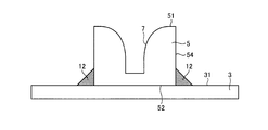
- the connecting member 5 is fixed to the accessory mounting plate 3 with the mold resin 12.
- the connecting member 5 has a side surface 54 that connects the facing surface 51 and the contact surface 52.
- the side surface 54 is a plane orthogonal to the attached connection surface 31.
- the attached connecting surface 31 of the attached mounting plate 3 and the side surface 54 of the connecting member 5 are fixed by the mold resin 12.
- the same effect as that of the first embodiment can be obtained also by this modification.
- the connecting member 5 may be fixed to a main mounting plate (not shown) with the mold resin 12, and protrusions (not shown) may be formed on the attached mounting plate 3.
- FIG. 14 is a diagram showing an accessory mounting plate 3 and a connecting member 5 according to a modified example 3 of the first embodiment.
- the connecting member 5 is fixed to the accessory mounting plate 3 with an adhesive 13 or a fusion metal.
- the attached connecting surface 31 of the attached mounting plate 3 and the contact surface 52 of the connecting member 5 are fixed via the adhesive 13.
- the connecting member 5 may be fixed to a main mounting plate (not shown) with an adhesive 13, and protrusions (not shown) may be formed on the attached mounting plate 3.
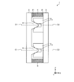
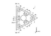
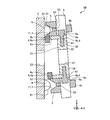
- FIG. 15 is a front view showing the attachment/detachment device 1 according to the fourth modification of the first embodiment. 16 is a cross-sectional view of the desorption device 1 shown in FIG. 15 taken along line XVI-XVI.
- the detachable device 1 includes a main mounting plate 2, an accessory mounting plate 3, three suction means 4, three first bolts 8a, three connecting members 5, and three. A second bolt 8b and the like are provided.
- the main mounting plate 2 is formed in a triangular shape when viewed from the front.
- the attached mounting plate 3 is formed in a triangular shape in a front view.
- a rectangular notch 34 in front view is formed on each side of the attached mounting plate 3.
- the main mounting plate 2 is formed to be slightly larger than the accessory mounting plate 3 in front view.
- a plurality of hemispherical protrusions 6 are formed on the main connecting surface 21 of the main mounting plate 2.
- the number of the projections 6 is not particularly limited, but is three in this embodiment. In FIG. 16, one protrusion 6 is hidden by the suction means 4 and is invisible.
- the attraction means 4 is a plate-shaped magnet in this modification.
- the suction means 4 is formed with an elongated hole-shaped first through hole 41 for passing the first bolt 8a.
- the first through hole 41 extends in the X-axis direction. Part of the suction means 4 is inserted into the notch 34 of the attachment plate 3.
- the first bolt 8a is a member for fixing the suction means 4 to the accessory mounting plate 3.
- the attachment plate 3 is formed with a first bolt hole 35 for fixing the first bolt 8a.
- a hole 7 is formed in the facing surface 51 of the connecting member 5 at a position facing the protrusion 6.
- the second contact surface 71 of the hole 7 is formed in a conical surface shape whose diameter increases toward the main mounting plate 2, but it may be spherical.
- one connecting member 5 is hidden behind the suction means 4 and is invisible.
- the second bolt 8b is a member for fixing the connecting member 5 to the accessory mounting plate 3.
- a second through hole 36 for passing the second bolt 8b is formed in the accessory mounting plate 3.
- the second through hole 36 extends from the accessory mounting surface 32 to the accessory connecting surface 31.
- the inner diameter of the second through hole 36 is formed larger than the shaft diameter of the second bolt 8b.
- a second bolt hole 55 for fixing the second bolt 8b is formed in the connecting member 5.
- the second bolt hole 55 is formed from the contact surface 52 to the hole 7.
- the second bolt hole 55 communicates with the hole 7.
- the connecting member 5 is fixed to the accessory mounting plate 3 by screwing the second bolt 8b passed through the second through hole 36 into the second bolt hole 55. Since the inner diameter of the second through hole 36 is formed to be larger than the shaft diameter of the second bolt 8b, when the second bolt 8b is loosened, the connecting member 5 is freely moved in the in-plane direction of the attached connecting surface 31 of the attached mounting plate 3. Can be moved to.
- the contact surface 52 of the connecting member 5 is in contact with the accessory connecting surface 31 of the accessory mounting plate 3.
- An opening 23 is formed in the central portion of the main mounting plate 2.
- An opening 37 is also formed in the center of the attached mounting plate 3.
- the openings 23 and 37 can be used as optical path holes for passing laser light.
- the shapes of the main mounting plate 2 and the accessory mounting plate 3 in front view may be other than the triangular shape.
- the number of the suction means 4, the first bolt 8a, the connecting member 5, and the second bolt 8b is set to 3 in this modification, but may be 1 or a plurality other than 3.
- the protrusion 6 may be formed on the connecting member 5, and the hole 7 may be formed on the main mounting plate 2 itself.
- the number of the connecting members 5 in which the protrusions 6 or the holes 7 are formed may be one or two, and the protrusions 6 or the holes 7 may be formed in the accessory mounting plate 3 itself. That is, at least one connecting member 5 having the projection 6 or the hole 7 may be formed.
- FIG. 17 is a diagram showing a main mounting plate 2 according to a modified example 5 of the first embodiment.
- the same reference numerals are given to the portions overlapping with the first embodiment, and the description thereof will be omitted.
- the holes 7 are formed in the main mounting plate 2.
- the connecting member is formed with a protrusion that contacts the inner surface of the hole 7.
- the main connecting surface 21 of the main mounting plate 2 is formed with a hole 7 into which the protrusion is fitted.
- a second contact surface 71 and a bottom surface 72 are formed on the inner surface of the hole 7.
- the bottom surface 72 is a plane orthogonal to the X-axis direction.
- the bottom surface 72 is a portion that does not come into contact with the protrusions.
- the second contact surface 71 is formed as a conical surface whose diameter increases from the bottom surface 72, which is the bottom of the hole 7, toward the opening 73.
- the second contact surface 71 is a portion that comes into contact with the protrusion.
- the second contact surface 71 is formed in a rotating surface shape having a central axis C2.
- the second contact surface 71 is formed in a shape that is axisymmetric with respect to the central axis C2.
- the central axis C2 is parallel to the normal direction N1 of the main connecting surface 21 of the main mounting plate 2. Also according to this modification, the same effect as that of the first embodiment can be obtained.
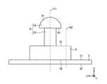
- FIG. 18 is a diagram showing an accessory mounting plate 3 and a connecting member 5 according to Modification 6 of the first embodiment.
- the same parts as those of the first embodiment described above are designated by the same reference numerals and the description thereof will be omitted.
- the protrusion 6 is formed on the connecting member 5. Although not shown, a hole into which the protrusion 6 fits is formed in the main mounting plate. On the facing surface 51 of the connecting member 5, there is formed a projection 6 that projects toward a main mounting plate (not shown).
- the protrusion 6 has a protrusion base end portion 63 and a protrusion tip end portion 64.
- the protrusion base end portion 63 is a cylindrical portion having a constant outer diameter.
- the protrusion tip portion 64 is a hemispherical portion whose diameter decreases toward the main mounting plate (not shown).
- a first contact surface 61 that contacts the inner surface of a hole (not shown) is formed on the protrusion tip 64.
- the first contact surface 61 is formed in a hemispherical shape whose diameter decreases toward the main mounting plate (not shown).
- the first contact surface 61 is formed in a rotation surface shape having a central axis C1.
- the first contact surface 61 is formed in a shape that is axisymmetric with respect to the central axis C1.
- the central axis C1 is orthogonal to the contact surface 52, which is a plane that contacts the attached connecting surface 31.
- the contact surface 52 is parallel to the accessory connecting surface 31.
- the central axis C1 is parallel to the normal direction N2 of the accessory connecting surface 31 of the accessory mounting plate 3. That is, the central axis C1 and the accessory connecting surface 31 of the accessory mounting plate 3 are orthogonal to each other.
- a step surface 65 is formed at the boundary between the protrusion base end portion 63 and the protrusion tip end portion 64. The step surface 65 is a plane orthogonal to the X-axis direction.
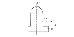
- FIG. 19 is a side view showing the protrusion 6 according to the modified example 7 of the first embodiment.
- 20 is a plan view of the protrusion 6 shown in FIG.
- the protrusion 6 according to Modification 7 has a protrusion base end portion 66 and a protrusion tip end portion 67.
- the protrusion tip portion 67 is a portion that comes into contact with the inner surface of a hole (not shown).
- the protrusion tip portion 67 has a circumferential surface 68 and a first contact surface 61.
- the circumferential surface 68 is continuous with the protrusion base end portion 66 and is formed to have a constant diameter.
- the first contact surface 61 is formed in an aspherical shape which is continuous with the tip of the circumferential surface 68 and whose diameter decreases as the distance from the projection base end portion 66 increases.
- the first contact surface 61 is formed in a rotation surface shape having a central axis C1.
- the first contact surface 61 is formed in a shape that is axisymmetric with respect to the central axis C1.
- the protrusion base end portion 66 is a portion that does not come into contact with the inner surface of the hole. That is, the projection base end portion 66 is a portion that does not contribute to the positioning of the main mounting plate and the accessory mounting plate (not shown), and therefore the shape of the projection base end portion 66 is not particularly limited.
- the shape of the projection base end portion 66 in plan view may be, for example, an irregular quadrangular shape larger than the outer diameter of the projection tip end portion 67 shown in FIG. As described above, the entire protrusion 6 does not have to be formed in a shape symmetrical with respect to the central axis C1.
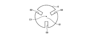
- FIG. 21 is a perspective view showing the protrusion 6 according to the modified example 8 of the first embodiment.
- FIG. 22 is a plan view of the protrusion 6 shown in FIG.
- FIG. 23 is a side view showing the hole 7 according to the modified example 8 of the first embodiment.
- FIG. 24 is a plan view of the hole 7 shown in FIG. 23.
- the same parts as those in the first embodiment described above are designated by the same reference numerals and the description thereof will be omitted.
- the entire shape of the protrusion 6 according to the modified example 8 is substantially hemispherical.
- the protrusion 6 has a first contact surface 61 and a cutout portion 69.
- the first contact surface 61 is a portion that contacts the inner surface of the hole 7 shown in FIG.
- the first contact surface 61 is formed in a hemispherical shape whose diameter decreases from the root of the protrusion 6 toward the tip.
- the first contact surface 61 is formed in a rotation surface shape having a central axis C1.
- the first contact surface 61 is formed in a shape that is axisymmetric with respect to the central axis C1.
- the number of notches 69 is not particularly limited, but in the present modification shown in FIG. 22, three notches 69 are provided at equal angles along the circumferential direction of the protrusion 6.
- the notch 69 is formed in a portion of the protrusion 6 that does not come into contact with the inner surface of the hole 7. In this way, the portion of the protrusion 6 that does not come into contact with the hole 7 does not have to be formed in a shape that is axisymmetric with respect to the central axis C1.
- a second contact surface 71 that comes into contact with the protrusion 6 is formed on the inner surface of the hole 7 according to the modified example 8.
- the second contact surface 71 is formed in a hemispherical shape whose diameter increases from the bottom 74 of the hole 7 toward the opening 73.
- the second contact surface 71 is formed in a rotating surface shape having a central axis C2.
- the second contact surface 71 is formed in a shape that is axisymmetric with respect to the central axis C2.
- the first contact surface 61 shown in FIG. 21 is reduced in diameter from the root of the projection 6 toward the tip.
- the second contact surface 71 shown in FIG. 23 increases in diameter from the bottom 74 of the hole 7 toward the opening 73.
- the first contact surface 61 and the second contact surface 71 are aligned in a state where the central axis C1 of the first contact surface 61 and the central axis C2 of the second contact surface 71 are aligned.
- a notch that does not come into contact with the first contact surface 61 may be formed around the hole 7. Also according to this modification, the same effect as that of the first embodiment can be obtained.
- FIG. 25 is a figure for demonstrating the attachment/detachment apparatus 1A concerning Embodiment 2 of this invention.
- the attachment / detachment device 1A according to the second embodiment is different from the first embodiment in that the connecting member 5 is attached to both the main attachment plate 2 and the accessory attachment plate 3.
- bolts for attaching the connecting member 5, through holes into which bolts are inserted, bolt holes, and the like are omitted.
- one connecting member 5 attached to the main mounting plate 2 is referred to as a first connecting member 5A
- the other connecting member 5 attached to the accessory mounting plate 3 is referred to as It is referred to as a second connecting member 5B.
- the same reference numerals are given to the parts that overlap with the first embodiment, and the description thereof will be omitted.
- the first connecting member 5A has a first contact surface 56 facing the main mounting plate 2 and a first facing surface 57 facing the accessory mounting plate 3.
- the first contact surface 56 is a plane that contacts the main connecting surface 21.
- the first contact surface 56 is parallel to the main connecting surface 21.
- a plurality of protrusions 6 projecting toward the attached mounting plate 3 are formed on the first facing surface 57.
- the plurality of protrusions 6 are arranged at intervals from each other.
- the shape of the protrusion 6 is not particularly limited, but in the present embodiment, it is a truncated cone shape whose diameter decreases toward the attachment plate 3.
- the protrusion 6 has a first contact surface 61 and a first top surface 62.
- the first contact surface 61 is formed in a conical surface shape whose diameter decreases toward the attachment plate 3.
- the first contact surface 61 is formed in a rotation surface shape having a central axis C1.
- the first contact surface 61 is formed in a shape that is axisymmetric with respect to the central axis C1.
- the central axis C1 is orthogonal to the first contact surface 56, which is a plane that contacts the main connecting surface 21.
- the first contact surface 56 is parallel to the main connecting surface 21.
- the central axis C1 is parallel to the normal direction N1 of the main connecting surface 21 of the main mounting plate 2. That is, the central axis C1 and the main connecting surface 21 of the main mounting plate 2 are orthogonal to each other.
- the first top surface 62 is continuous with the tip of the first contact surface 61.
- the first top surface 62 is a plane orthogonal to the X-axis direction.
- the second connecting member 5B has a second contact surface 58 facing the accessory mounting plate 3 and a second facing surface 59 facing the main mounting plate 2.
- the configuration of the second connecting member 5B is similar to that of the connecting member 5 according to the first embodiment.
- a hole 7 into which the protrusion 6 is fitted is formed in the second facing surface 59.
- the second contact surface 71 formed on the inner surface of the hole 7 is formed in a rotating surface shape having the central axis C2.
- the second contact surface 71 is formed in a shape that is axisymmetric with respect to the central axis C2.
- the central axis C2 is orthogonal to the second contact surface 58, which is a plane that contacts the attached connecting surface 31.
- the second contact surface 58 is parallel to the accessory connecting surface 31.
- the central axis C2 is parallel to the normal direction N2 of the accessory connecting surface 31 of the accessory mounting plate 3. That is, the central axis C2 and the accessory connecting surface 31 of the accessory mounting plate 3 are orthogonal to each
- the main mounting plate 2 and the accessory mounting plate 3 are formed with through holes for passing bolts, respectively.
- the inner diameter of each through hole is formed larger than the shaft diameter of the bolt.
- Bolt holes for fixing bolts are formed in the first connecting member 5A and the second connecting member 5B, respectively.
- the first connecting member 5A is fixed to the main mounting plate 2 by screwing the bolt passed through the through hole of the main mounting plate 2 into the bolt hole of the first connecting member 5A.
- the second connecting member 5B is fixed to the attached mounting plate 3 by screwing the bolt passed through the through hole of the attached mounting plate 3 into the bolt hole of the second connecting member 5B.
- the main mounting plate 2 to which the first connecting member 5A is fixed is the first mounting plate, and the main mounting target 9 (not shown) mounted on the main mounting plate 2 is the first mounting target.
- the main connecting surface 21 is the first connecting surface and the main mounting surface 22 is the first mounting surface.
- the accessory mounting plate 3 to which the second connecting member 5B is fixed is the second mounting plate, and the accessory mounting object 10 (not shown) attached to the accessory mounting plate 3 is the second mounting object.
- the attached connecting surface 31 is the second connecting surface
- the attached mounting surface 32 is the second mounting surface.
- any one of the fixing methods of the first embodiment and the first to third modifications described above may be used.
- the first connecting member 5A having the protrusion 6 may be fixed to the main mounting plate 2 in advance.
- the desorption device 1A can be assembled according to the procedure of the assembling method according to the first embodiment described above.
- the same effect as that of the first embodiment can be obtained. That is, when the central axis C1 of the protrusion 6 and the central axis C2 of the hole 7 are aligned with each other, the main connecting surface 21 of the main mounting plate 2 and the accessory connecting surface 31 of the accessory mounting plate 3 may be in a strictly parallel state. Therefore, if such a desorption device 1A is used in, for example, a laser processing machine, the actual trajectory of the laser light passing through the desorption device 1A and the design optical path match, and a laser processing machine capable of processing with higher quality than the conventional one can be obtained. realizable.
- the positional relationship between the main mounting plate 2 and the accessory mounting plate 3 is accurately determined. That is, in the present embodiment, it is possible to obtain the attachment / detachment device 1A having high positioning accuracy when the main mounting plate 2 and the accessory mounting plate 3 are connected.
- a desorption device 1A is used in, for example, a laser processing machine, a laser beam can be passed through an optical path as designed, and a laser processing machine having high beam quality can be realized.
- the contact position between the protrusion 6 and the hole 7 is uniquely determined, even if the main mounting plate 2 and the accessory mounting plate 3 are once separated and then reconnected, the main mounting plate 2 is before and after the separation. There is no deviation in the positional relationship between the and the attached mounting plate 3.
- a detaching device 1A is used for a laser beam machine, for example, it is not necessary to readjust the installation angle of the transmission mirror every time the main mounting plate 2 and the accessory mounting plate 3 are connected, and the laser beam machine having high productivity is obtained. Can be realized.
- the protrusion 6 is formed in the first connecting member 5A and the hole 7 is formed in the second connecting member 5B, but the present invention is not limited thereto.
- the hole 7 may be formed in the first connecting member 5A and the protrusion 6 may be formed in the second connecting member 5B.
- the first connecting member 5A and the second connecting member 5B in which the protrusion 6 is formed may be used in combination with the first connecting member 5A and the second connecting member 5B in which the hole 7 is formed.
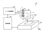
- FIG. 26 is a diagram for explaining a configuration example of the laser processing machine 100 according to the third embodiment of the present invention.
- the third embodiment an example in which the desorption device 1 according to the first embodiment is applied to the laser processing machine 100 is shown.
- the same reference numerals are given to the parts that overlap with the first embodiment, and the description thereof will be omitted.
- the laser processing machine 100 is a machine that processes, welds, and the like the work W that is the workpiece.
- the laser processing machine 100 includes a laser light oscillator 102 that emits laser light, an optical path pipe 103 through which the laser light emitted from the laser light oscillator 102 passes, a processing head 104 that emits laser light to the work W, and an optical path pipe.
- the attachment/detachment device 1 that connects the processing head 103 and the processing head 104 is provided.
- the optical path pipe 103 is attached to the main attachment surface 22 of the attachment / detachment device 1.
- the processing head 104 is attached to the attachment mounting surface 32 of the desorption device 1.
- the connecting member 5 is fixed to the attached mounting plate 3.
- the main mounting plate 2 to which the connecting member 5 is not fixed is the second mounting plate, and the optical path pipe 103 attached to the main mounting plate 2 is the second mounting target.
- the main connecting surface 21 is the second connecting surface and the main mounting surface 22 is the second mounting surface.
- the accessory mounting plate 3 to which the connecting member 5 is fixed is the first mounting plate, and the processing head 104 mounted on the accessory mounting plate 3 is the first mounting target.
- the accessory connection surface 31 is the first connection surface and the accessory attachment surface 32 is the first attachment surface.
- the laser beam machine 100 is mounted across the main mounting plate 2 and the auxiliary mounting plate 3 and covers the desorption device 1, a movable table 106 on which the workpiece W is mounted, a laser light oscillator 102 and a movable table.
- a control device 107 for controlling the table 106 is provided.
- the movable table 106 can change the relative position of the work W with respect to the machining head 104 in the X-axis direction and the Y-axis direction under the control of the control device 107. Note that in FIG. 26, a cross section of the bellows 105 is shown for convenience.
- the control device 107 controls the laser light oscillator 102 and causes the laser light oscillator 102 to emit laser light.
- the laser light emitted from the laser light oscillator 102 propagates in the optical path pipe 103, passes through the openings 23 and 37 formed in the desorption device 1, and is incident on the processing head 104.
- the processing head 104 includes a transmission mirror 111 and a lens 110.
- the laser light incident on the processing head 104 is focused on the surface of the work W by the transmission mirror 111 and the lens 110.
- the work W is heated to a high temperature by the laser beam focused on the surface and melts.
- the movable table 106 on which the work W is placed is moved in the X-axis and Y-axis directions under the control of the control device 107, and the work W is cut or welded into a desired shape.
- the processing head 104 may collide with the work W, the movable table 106, or the like during the operation check of the laser processing machine 100 or the processing of the work W by the laser processing machine 100.
- the laser processing machine 100 has a collision detection sensor (not shown), and when a collision of the processing head 104 is detected by the collision detection sensor, a function of moving the movable table 106 or urgently stopping the operation of the laser optical oscillator 102. have.
- the response time which is the time from the timing when the machining head 104 collides with the work W or the movable table 106 to the emergency stop of the movement of the work W by the movable table 106, is long.
- the detaching device 1 is not provided in the laser processing machine 100, the impact force due to the collision with the movable table 106 or the like is transmitted to the processing head 104 as it is. Therefore, the processing head 104, the movable table 106, and the like may fail.
- the laser processing machine 100 since the laser processing machine 100 is provided with the attachment/detachment device 1, the connection between the processing head 104 and the optical path pipe 103 is released before a force that causes a failure is applied at the time of a collision. Therefore, in the attachment / detachment device 1, failures of the processing head 104, the movable table 106, and the like can be suppressed.
- the operation when the processing head 104 collides with the work W, the movable table 106, or the like will be specifically described.
- the processing head 104 collides with the work W, the movable table 106, etc., the impact force due to the collision is transmitted to the desorption device 1.
- the collision detection sensor detects the collision of the processing head 104
- the laser processing machine 100 activates the emergency stop function.
- the processing head 104 has a large impact force due to a collision due to inertial force or the like.
- the bellows 105 since the bellows 105 is mounted across the main mounting plate 2 and the accessory mounting plate 3, the bellows 105 holds the machining head 104 via the accessory mounting plate 3 so that the machining head 104 does not drop. As a result, failure of the processing head 104 due to dropping is prevented.
- the attachment/detachment device 1 is reconnected, and the processing of the work W by the laser processing machine 100 is restarted.
- the desorption device 1 Since the desorption device 1 has good positioning accuracy as described above, it is possible to suppress the occurrence of the optical axis shift of the laser light at the time of recoupling, and the laser processing machine 100 after the desorption device 1 recoupling is performed. Machining can be performed with high accuracy. Therefore, the processing by the laser processing machine 100 can be restarted without adjusting the alignment at the time of reconnecting the attachment / detachment device 1.
- the laser processing machine 100 includes the desorption device 1 and the processing head 104 that is fixed to the accessory mounting plate 3 and that processes or welds the work W by laser light. Thereby, the laser processing machine 100 can separate the optical path by the collision force of the object colliding with the processing head 104, and avoid damage to the processing head 104. Further, since the attachment / detachment device 1 has high-precision position reproducibility, it is possible to suppress the occurrence of optical axis deviation of the laser beam, and the laser processing machine 100 does not need to adjust the alignment when the attachment / detachment device 1 is reconnected. Processing can be resumed.
- the laser beam passes through the openings 23 and 37 which are the optical path holes formed in the main mounting plate 2 and the accessory mounting plate 3. Thereby, the desorption device 1 can be easily applied to the laser processing machine 100.
- the desorption devices 1 and 1A may be applied to processing machines other than the laser processing machine 100. That is, in the present embodiment, the laser processing machine 100 is illustrated as a processing machine equipped with the attachment / detachment devices 1, 1A, but the attachment / detachment device 1, 1A sends out a substance from the processing head and causes the substance to collide with the work. It can be mounted on a processing machine that performs processing.
- the processing machine that can mount the desorption devices 1 and 1A is, for example, a plasma processing machine, a water jet processing machine, a gas cutting processing machine, or a milling processing machine.
- the laser processing machine 100 moves the relative position between the work W and the processing head 104 by the movable table 106 on which the work W is placed, but the moving means may be provided instead of the movable table 106.
- the laser processing machine 100 is provided with a moving unit that moves the processing head 104 in the three axial directions of the X axis, the Y axis, and the Z axis, instead of the movable table 106, and processes the three-dimensionally shaped work W. It may be configured to be possible.
- the moving unit may be configured to move the laser light oscillator 102 and the optical path pipe 103 so that the processing head 104 connected to the optical path pipe 103 via the attachment/detachment device 1 moves.
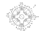
- Fourth Embodiment 27 is a front view which shows the attachment/detachment apparatus 1B concerning Embodiment 4 of this invention.
- the same reference numerals are given to the parts that overlap with the first embodiment, and the description thereof will be omitted.
- the desorption device 1B includes a main mounting plate 2, an accessory mounting plate 3, four suction means 4, four first bolts 8a, four connecting members 5, and four coupling members 5.
- a second bolt 8b and the like are provided.
- the main mounting plate 2 is formed in a circular shape when viewed from the front.
- the attached mounting plate 3 is formed in a substantially cross shape when viewed from the front.
- Four notches 34 are formed on the attached mounting plate 3 at equal intervals.
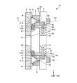
- FIG. 28 is a sectional view taken along line XXVIII-XXVIII of the desorption device 1B shown in FIG. Note that, in FIG. 28, for convenience of description, the connecting member 5 and the second bolt 8b are hatched in cross section. As shown in FIG. 28, a plurality of hemispherical projections 6 are formed on the main connecting surface 21 of the main mounting plate 2. The number of the protrusions 6 is not particularly limited, but is four in the present embodiment. In FIG. 28, only the two protrusions 6 are shown.
- An opening 23 is formed in the center of the main mounting plate 2.
- An opening 37 is also formed in the center of the attached mounting plate 3. For example, when the desorption device 1B is used in a laser processing machine, the openings 23 and 37 can be used as optical path holes for passing laser light.
- the attraction means 4 has a magnet 4a and a plate portion 4b.
- the magnet 4 a has a suction surface 4 c facing the main mounting plate 2.
- the suction surface 4c of the magnet 4a is attracted to the main connecting surface 21 of the main mounting plate 2.
- the plate portion 4b is a metal member formed separately from the magnet 4a.
- the plate portion 4b is fixed to the surface of the magnet 4a facing opposite to the suction surface 4c.
- the material of the plate portion 4b is, for example, stainless steel.
- the plate portion 4b has a flat surface 4d orthogonal to the suction surface 4c of the magnet 4a.
- a first through hole 41 for passing the first bolt 8a is formed in the plate portion 4b.
- the first through hole 41 is open to the flat surface 4d.
- the first through hole 41 is formed in an elongated hole shape that is longer in the X-axis direction than in the Z-axis direction. A part of the plate portion 4b is inserted into the cutout portion 34 of the accessory mounting plate 3.
- the first bolt 8a is a member for fixing the suction means 4 to the attached mounting plate 3.
- the attachment plate 3 is formed with a first bolt hole 35 for fixing the first bolt 8a.
- a hole 7 is formed in the facing surface 51 of the connecting member 5 at a position facing the protrusion 6.
- the second contact surface 71 of the hole 7 is formed in a conical surface shape whose diameter increases toward the main mounting plate 2, but it may be spherical.
- the second bolt 8b is a member for fixing the connecting member 5 to the attached mounting plate 3.
- a second through hole 36 for passing the second bolt 8b is formed in the accessory mounting plate 3.
- the second through hole 36 extends from the accessory mounting surface 32 to the accessory connecting surface 31.
- the inner diameter of the second through hole 36 is formed to be larger than the shaft diameter of the second bolt 8b.
- the connecting member 5 is formed with a second bolt hole 55 for fixing the second bolt 8b.
- the second bolt hole 55 is formed from the contact surface 52 to the hole 7.
- the second bolt hole 55 communicates with the hole 7.
- the connecting member 5 is fixed to the accessory mounting plate 3 by screwing the second bolt 8b passed through the second through hole 36 into the second bolt hole 55.
- the contact surface 52 of the connecting member 5 is in contact with the accessory connecting surface 31 of the accessory mounting plate 3.
- the main attachment plate 2 to which the connecting member 5 is not fixed is the second attachment plate, and the main attachment object 9 (not shown) attached to the main attachment plate 2 is the second attachment object.
- the main connecting surface 21 is the second connecting surface and the main mounting surface 22 is the second mounting surface.
- the accessory mounting plate 3 to which the connecting member 5 is fixed is the first mounting plate, and the accessory mounting object 10 (not shown) that is mounted on the accessory mounting plate 3 is the first mounting object.
- the accessory connection surface 31 is the first connection surface and the accessory attachment surface 32 is the first attachment surface.
- the central axis C1 of the protrusion 6 and the central axis C2 of the hole 7 coincide with each other.
- the plurality of protrusions 6 are arranged so that their central angles are equal.
- the protrusions 6 are arranged equiangularly with the same center as the base point.
- the number of the protrusions 6 is not particularly limited, but is four in the present embodiment.
- the virtual line connecting the spaces is a polygon L1.
- the polygon L1 is a regular quadrangle. That is, the four protrusions 6 are arranged at the positions corresponding to the vertices of the regular quadrangle.
- the holes 7 are arranged so that their central angles are the same. In other words, the holes 7 are arranged equiangularly with the same center as the base point.
- the number of holes 7 is four in the present embodiment, but is not particularly limited as long as it is the same as the number of protrusions 6. Positions of the central axes C2 of the adjacent holes 7 when the central axes C2 of the four holes 7 are projected on a virtual plane parallel to the main connecting surface 21 of the main mounting plate 2 or the auxiliary connecting surface 31 of the auxiliary mounting plate 3.
- the virtual line connecting the spaces is a polygon L2. In this embodiment, since the four holes 7 are arranged at equal angles, the polygon L2 is a regular quadrangle.
- the four holes 7 are arranged at positions corresponding to the respective vertices of the regular quadrangle. Since the central axis C1 of the protrusion 6 and the central axis C2 of the hole 7 coincide with each other, the polygon L1 and the polygon L2 are regular squares having the same size.
- the positions of the central axes C1 of the four protrusions 6 are the virtual planes.
- the suction means 4 and the projections 6 are arranged so as to be inside the polygon L1 that connects the positions of the central axes C1 of the adjacent projections 6 when projected onto.
- the polygon L1 is formed by projecting the respective central axes C1 of the plurality of protrusions 6 onto an imaginary plane parallel to the main connecting surface 21 of the main mounting plate 2 or the accessory connecting surface 31 of the accessory mounting plate 3.
- any polygon may be used as long as it connects the positions of the central axis C1 and each interior angle is less than 180 degrees and the sum of the interior angles is maximum.
- the suction means 4 is projected on a virtual plane parallel to the main connecting surface 21 of the main mounting plate 2 or the auxiliary connecting surface 31 of the auxiliary mounting plate 3, the positions of the central axes C2 of the four holes 7 are defined as above.
- the suction means 4 and the holes 7 are arranged so as to be inside the polygon L2 that connects the positions of the central axes C2 of the adjacent holes 7 when projected onto the virtual plane.
- the polygon L2 is formed by projecting the respective central axes C2 of the plurality of holes 7 onto an imaginary plane parallel to the main connecting surface 21 of the main mounting plate 2 or the auxiliary connecting surface 31 of the auxiliary mounting plate 3. Any polygon may be used as long as it connects the positions of the central axis C2 and each interior angle is less than 180 degrees and the sum of the interior angles is maximum.
- the number of protrusions 6 and holes 7 may be three or four or more. That is, the polygons L1 and L2 may be polygons such as a triangle, a quadrangle, and a pentagon. Further, the polygons L1 and L2 are not limited to regular polygons.
- the central axes of the first through hole 41 of the suction means 4 and the first bolt hole 35 of the accessory mounting plate 3 are parallel to the accessory connecting surface 31 of the accessory mounting plate 3.
- the central axes of the first through holes 41 of the suction means 4 and the first bolt holes 35 of the accessory mounting plate 3 shown in FIG. 28 are parallel to the Z axis direction and orthogonal to the X axis direction and the Y axis direction. doing.
- the suction means 4 can be freely moved in the X-axis direction and the Y-axis direction or the Z-axis direction. Therefore, after the position of the attraction means 4 is adjusted so that the attraction surface 4c of the magnet 4a is in close contact with the main mounting plate 2, the attraction means 4 can be fixed to the accessory mounting plate 3 with the first bolt 8a.
- FIG. 30 is a front view showing a desorption device 1B according to the fourth embodiment.
- the projection 6 that serves as a fulcrum of rotation of the attachment/detachment device 1B when a machining head (not shown) collides with the work is hatched.
- 31 is a cross-sectional view taken along line XXXI-XXXI of the desorption device 1B shown in FIG.
- the connecting member 5 and the second bolt 8b are hatched in cross section.
- the accessory mounting plate 3 rotates relative to the main mounting plate 2 with the projection 6 on the upper side of the paper of FIG. 31 as a fulcrum, and the connecting member 5 on the lower side of the paper of FIG. There is.
- the position when the suction means 4 is projected on a virtual plane parallel to the main connecting surface 21 of the main mounting plate 2 or the auxiliary connecting surface 31 of the auxiliary mounting plate 3 is outside the polygons L1 and L2.
- the suction means 4 the protrusions 6 and the holes 7 are arranged, the suction means 4 on the upper side of the paper in FIG. 31 is pressed against the main connecting surface 21 of the main mounting plate 2.
- the suction means 4 is easily damaged, and the frequency of replacement of the suction means 4 increases.
- the position when the suction means 4 is projected on the virtual plane parallel to the main connecting surface 21 of the main mounting plate 2 or the auxiliary connecting surface 31 of the auxiliary mounting plate 3 is four protrusions.
- the suction means 4 and the protrusion 6 are arranged so as to be.
- the positions when the suction means 4 is projected on a virtual plane parallel to the main connecting surface 21 of the main mounting plate 2 or the auxiliary connecting surface 31 of the auxiliary mounting plate 3 are each of the four holes 7.
- the central axes C2 of the two are projected to the virtual plane, the positions of the central axes C2 of the adjacent holes 7 are connected to each other so as to be inside the polygon L2 in which each interior angle is less than 180 degrees and the sum of the interior angles is maximum.
- the suction means 4 and the hole 7 are arranged in the. Therefore, the suction means 4 on the upper side of the paper surface of FIG. 31 always separates from the main mounting plate 2. As a result, the suction means 4 is less likely to be damaged, so that the frequency of replacement of the suction means 4 is reduced.
- FIG. 32 is a diagram for explaining a configuration example of the laser processing machine 100A according to the fifth embodiment of the present invention.
- the desorption device 1B according to the fourth embodiment is applied to the laser processing machine 100A.
- the same reference numerals are given to the parts that overlap with the fourth embodiment, and the description thereof will be omitted.
- the desorption device 1B is illustrated in a simplified manner.
- the chain line arrow in FIG. 32 indicates the traveling direction of the laser light.
- the laser processing machine 100A includes an arm 112, a rotation mechanism 113, a light condensing unit 114, and a desorption device 1B.
- the arm 112 has a horizontal portion 115, a first inclined portion 116, a second inclined portion 117, a third inclined portion 118, and a vertical portion 119.
- the laser light passes through the horizontal portion 115, the first inclined portion 116, the second inclined portion 117, the third inclined portion 118, and the vertical portion 119 in this order.
- the arm 112 becomes a part of the processing head 104.
- the horizontal portion 115 is a portion extending in the horizontal direction. One end of the horizontal portion 115 is connected to the rotation mechanism 113.
- the first inclined portion 116 is a portion that inclines downward from the other end of the horizontal portion 115.
- the second inclined portion 117 is a portion that inclines upward from the lower end of the first inclined portion 116.
- the third sloping portion 118 is located on an extension of the second sloping portion 117 and is a portion that slopes up.
- the second inclined portion 117 and the third inclined portion 118 are connected to each other via the attachment/detachment device 1B.
- the vertical portion 119 is a portion extending downward from the upper end of the third inclined portion 118.
- the inclination angles of the first inclined portion 116, the second inclined portion 117, and the third inclined portion 118 with respect to the vertical axis are, for example, 45 degrees.
- the material of the arm 112 is iron in the present embodiment, but a metal other than iron, ceramics, resin, or the like may be used as long as it has the necessary physical properties.
- a second optical path hole 121 for passing laser light is formed inside the arm 112.
- the second optical path hole 121 is formed with a plurality of linear portions 122 extending linearly and a curved portion 123 connecting adjacent straight portions 122 and straight portions 122.
- An optical component (not shown) that reflects the laser light is installed on the curved portion 123.
- the rotation mechanism 113 is a mechanism that rotates the arm 112 about the first axis 125.
- the rotation mechanism 113 becomes a part of the processing head 104.
- the first shaft 125 is a rotating shaft extending in the vertical direction. Although illustration is omitted, a rotation mechanism is also arranged inside the first inclined portion 116.
- the rotation mechanism arranged inside the first inclined portion 116 is a mechanism for rotating the second inclined portion 117, the third inclined portion 118, and the vertical portion 119 around the second shaft 126.
- the second shaft 126 is a rotation shaft parallel to the extending direction of the first inclined portion 116.
- a third optical path hole 124 for passing a laser beam is formed inside the rotation mechanism 113.
- the third optical path hole 124 of the rotating mechanism 113 and the second optical path hole 121 of the arm 112 communicate with each other.
- the condensing unit 114 has an optical system that condenses laser light and a nozzle.
- the light collecting unit 114 becomes a part of the processing head 104.
- the light collecting unit 114 is connected to the tip of the arm 112. Specifically, the light collecting section 114 is connected to the lower end of the vertical section 119.
- the detaching/attaching device 1B connects the second inclined portion 117 and the third inclined portion 118 in a separable manner.
- the second inclined portion 117 is attached to the main attachment surface 22 of the desorption device 1B.
- the third inclined portion 118 is attached to the attachment mounting surface 32 of the detaching/attaching device 1B.
- the connecting member 5 is fixed to the attached mounting plate 3.
- the first optical path hole 120 of the attachment / detachment device 1B and the second optical path hole 121 in the second inclined portion 117 and the third inclined portion 118 communicate with each other.
- the attachment / detachment device 1B has the second inclined portion 117 and the third inclined portion 117 in a state where the central axis of the first optical path hole 120 and the central axis of the second optical path hole 121 in the second inclined portion 117 and the third inclined portion 118 coincide with each other. It is arranged so as to be located between the portion 118 and the portion 118.
- the term “match” as used herein includes not only a perfect match but also a slightly deviated state that is not a strict match.
- the main attachment plate 2 to which the connecting member 5 is not fixed is the second attachment plate, and the second inclined portion 117 attached to the main attachment plate 2 is the second attachment object.
- the main connecting surface 21 is the second connecting surface and the main mounting surface 22 is the second mounting surface.
- the attachment mounting plate 3 to which the connecting member 5 is fixed is the first attachment plate, and the third inclined portion 118 attached to the attachment mounting plate 3 is the first attachment target.
- the accessory connection surface 31 is the first connection surface and the accessory attachment surface 32 is the first attachment surface.
- the laser beam passes through the third optical path hole 124 of the rotation mechanism 113 and enters the second optical path hole 121 of the arm 112.
- the laser light that has entered the second optical path hole 121 of the arm 112 passes through the first optical path hole 120 of the attachment/detachment device 1B and is transmitted by being reflected by the optical components and reaches the light condensing unit 114.
- the laser light condensed by the condensing unit 114 is emitted from the nozzle toward the work together with the assist gas.
- the attachment/detachment device 1B is arranged so as to be located between the second inclined portion 117 and the third inclined portion 118, so that the machining head 104 collides head-on with the workpiece or is laterally attached to the workpiece. Even if it hits, the main mounting plate 2 and the accessory mounting plate 3 are easily separated. Therefore, the impact force applied to the processing head 104 at the time of collision can be reduced.
- the third inclined portion 118 to which the attachment/detachment device 1B is attached is connected to the light collecting portion 114 via the vertical portion 119, so that the main attachment plate 2 and the accessory attachment plate 3 can be attached with a smaller impact force. Since they can be separated, the impact force applied to the processing head 104 at the time of collision can be further reduced.
- the central axis of the first optical path hole 120 of the desorption device 1B and the central axis of the second optical path hole 121 in the second inclined portion 117 and the third inclined portion 118 are aligned.
- the desorption device 1B may be mounted on the laser processing machine 100A having the processing head 104 for a two-dimensional work, or mounted on the laser processing machine 100A having the processing head 104 for a three-dimensional work. Good.
- the machining head 104 for a three-dimensional workpiece is used, the machining head 104 is required to be positioned with higher accuracy than the machining head 104 for a two-dimensional workpiece. Therefore, when the desorption device 1B having high positioning accuracy when the main mounting plate 2 and the accessory mounting plate 3 are connected is mounted on the laser processing machine 100A having the processing head 104 for a three-dimensional work, the processing head 104 can be accurately operated. Can be positioned well.
- the laser processing machine 100A is illustrated as a processing machine equipped with the desorption device 1B, but the desorption device 1B sends out a substance from the machining head and collides the substance with the work to perform machining. It can be mounted on a machine.
- the processing machine on which the desorption device 1B can be mounted is, for example, a plasma processing machine, a water jet processing machine, a gas cutting processing machine, and a milling processing machine.
Landscapes
- Engineering & Computer Science (AREA)
- Mechanical Engineering (AREA)
- Physics & Mathematics (AREA)
- Optics & Photonics (AREA)
- Plasma & Fusion (AREA)
- Connection Of Plates (AREA)
- Laser Beam Processing (AREA)
- Machine Tool Units (AREA)
- Jigs For Machine Tools (AREA)
- Auxiliary Devices For Machine Tools (AREA)
Abstract
L'invention concerne un dispositif de séparation et de fixation (1) équipé : d'une plaque de fixation principale (2) à laquelle est fixé un objet principal fixé (9) ; d'une plaque de fixation d'accessoire (3) sur laquelle est fixé un objet accessoire fixé (10) ; d'un moyen de fixation par aspiration (4) destiné à relier de manière amovible la plaque de fixation principale (2) et la plaque de fixation d'accessoire (3) ; et des éléments de liaison (5) qui sont disposés entre la plaque de fixation principale (2) et la plaque de fixation d'accessoire (3) et qui sont formés séparément de la plaque de fixation principale (2) et de la plaque de fixation d'accessoire (3). Les éléments de liaison (5) sont fixés à la plaque de fixation d'accessoire (3). Des protubérances (6) qui font saillie vers les éléments de liaison (5) sont formées sur la plaque de fixation principale (2). Un trou (7) dans lequel s'insère chaque protubérance (6) est formé dans chaque élément de liaison (5). Une première surface de contact (61), se présentant sous forme de surface de révolution, est formée sur chaque protubérance (6). Une seconde surface de contact (71), se présentant sous forme de surface de révolution, est formée sur une surface interne de chaque trou (7). Dans un état dans lequel un axe central (C1) de chaque protubérance (6) et un axe central (C2) de chaque trou (7) coïncident, les premières surfaces de contact (61) et les secondes surfaces de contact (71) sont en contact les unes avec les autres.
Priority Applications (4)
| Application Number | Priority Date | Filing Date | Title |
|---|---|---|---|
| CN201980093461.9A CN113508003B (zh) | 2019-03-06 | 2019-12-04 | 拆装装置、加工机及加工头 |
| JP2021503406A JP7175376B2 (ja) | 2019-03-06 | 2019-12-04 | 脱着装置、加工機および加工ヘッド |
| US17/435,035 US11833609B2 (en) | 2019-03-06 | 2019-12-04 | Attaching and detaching apparatus, machining device, and machining head |
| JP2022178709A JP7357748B2 (ja) | 2019-03-06 | 2022-11-08 | 脱着装置、加工機および加工ヘッド |
Applications Claiming Priority (2)
| Application Number | Priority Date | Filing Date | Title |
|---|---|---|---|
| JP2019040714 | 2019-03-06 | ||
| JP2019-040714 | 2019-03-06 |
Publications (1)
| Publication Number | Publication Date |
|---|---|
| WO2020179162A1 true WO2020179162A1 (fr) | 2020-09-10 |
Family
ID=72337845
Family Applications (1)
| Application Number | Title | Priority Date | Filing Date |
|---|---|---|---|
| PCT/JP2019/047419 Ceased WO2020179162A1 (fr) | 2019-03-06 | 2019-12-04 | Dispositif de séparation et de fixation, machine de traitement et tête de traitement |
Country Status (4)
| Country | Link |
|---|---|
| US (1) | US11833609B2 (fr) |
| JP (2) | JP7175376B2 (fr) |
| CN (1) | CN113508003B (fr) |
| WO (1) | WO2020179162A1 (fr) |
Families Citing this family (2)
| Publication number | Priority date | Publication date | Assignee | Title |
|---|---|---|---|---|
| DE102017121526A1 (de) * | 2017-09-15 | 2019-03-21 | Rollomatic S.A. | Vorrichtung zur Ausrichtung und Positionierung eines Werkstücks relativ zu einem Laserstrahl einer Laserbearbeitungsmaschine |
| JP6748761B1 (ja) * | 2019-05-14 | 2020-09-02 | Dmg森精機株式会社 | レーザ照射ヘッド |
Citations (7)
| Publication number | Priority date | Publication date | Assignee | Title |
|---|---|---|---|---|
| JPS6210985U (fr) * | 1985-07-04 | 1987-01-23 | ||
| JPH0417382U (fr) * | 1990-05-25 | 1992-02-13 | ||
| JPH04104271U (ja) * | 1991-02-07 | 1992-09-08 | 株式会社小松製作所 | 熱切断機用ト−チの破損防止装置 |
| JPH07178546A (ja) * | 1993-12-22 | 1995-07-18 | Koike Sanso Kogyo Co Ltd | トーチ保持構造 |
| JP2012110907A (ja) * | 2010-11-22 | 2012-06-14 | Mitsubishi Electric Corp | 加工装置 |
| CN203045163U (zh) * | 2012-12-27 | 2013-07-10 | 苏州领创激光科技有限公司 | 撞击自我保护可恢复加工头 |
| CN207806910U (zh) * | 2018-02-06 | 2018-09-04 | 郑州英博锐电子技术有限公司 | 一种用于激光切割机器人的防撞激光切割头 |
Family Cites Families (47)
| Publication number | Priority date | Publication date | Assignee | Title |
|---|---|---|---|---|
| US1852599A (en) * | 1931-02-18 | 1932-04-05 | Zaiger Max | Windshield heater |
| US2002722A (en) * | 1933-10-27 | 1935-05-28 | Fulton Co | Frost shield |
| US2172461A (en) * | 1936-08-24 | 1939-09-12 | Anthony C Fischer | Form clamp |
| US3634649A (en) * | 1970-03-19 | 1972-01-11 | Reynolds Metals Co | Apparatus for and method of joining stranded cable |
| US4627565A (en) * | 1982-03-18 | 1986-12-09 | Lomerson Robert B | Mechanical bonding of surface conductive layers |
| US4492355A (en) * | 1982-03-21 | 1985-01-08 | Bylin Heating Systems, Inc. | Magnetic mount for heating module |
| US4585197A (en) * | 1983-09-06 | 1986-04-29 | James P. Liautaud | Swivel base assembly |
| US4517070A (en) * | 1984-06-28 | 1985-05-14 | General Motors Corporation | Magnetron sputtering cathode assembly and magnet assembly therefor |
| US4595186A (en) * | 1984-12-20 | 1986-06-17 | Reed Richard A | Rotating welding fixture |
| US4615514A (en) * | 1985-01-29 | 1986-10-07 | Hamlin Jerry J | Holding apparatus and method for securely positioning members to be joined by welding or the like |
| US4717131A (en) * | 1986-09-03 | 1988-01-05 | David Dugas | Welding clamp |
| US4851640A (en) * | 1986-10-17 | 1989-07-25 | The Budd Company | Frost plug heater |
| DE3710472A1 (de) * | 1987-03-30 | 1988-10-20 | Erowa Ag | Vorrichtung zur loesbaren befestigung von werkzeugen an einem handhabungsgeraet |
| US4883570A (en) * | 1987-06-08 | 1989-11-28 | Research-Cottrell, Inc. | Apparatus and method for enhanced chemical processing in high pressure and atmospheric plasmas produced by high frequency electromagnetic waves |
| US4824231A (en) * | 1987-07-20 | 1989-04-25 | Ross Quintana | Broad angle rear view mirror assembly |
| NL8702239A (nl) * | 1987-09-18 | 1989-04-17 | Allen Derek Morley | Inrichting voor het vastklemmen van twee aan elkaar vast te lassen metalen voorwerpen. |
| US4831240A (en) * | 1987-10-08 | 1989-05-16 | Hester Industries, Inc. | Electrical high current industrial oven or fryer compression connection |
| US4807947A (en) * | 1988-01-20 | 1989-02-28 | Morgan Container Corp. | Display case mounting system for shelving |
| US5247157A (en) * | 1990-02-20 | 1993-09-21 | Spendlove Max J | Apparatus for developing heat within conductive materials using heat-resistant ribbon heaters |
| AUPN784696A0 (en) * | 1996-02-01 | 1996-02-22 | Wickett, Geoffrey Malcolm | Liquid valve |
| US5822918A (en) * | 1996-11-25 | 1998-10-20 | Barbara Helfman | Planter |
| US5782445A (en) * | 1996-12-11 | 1998-07-21 | Mg Systems & Welding, Inc. | Mounting and locating device for a breakaway tool holder |
| US5839647A (en) * | 1997-07-22 | 1998-11-24 | Mse Technology Applications, Inc. | Welding clamp for pipe fittings |
| US6103183A (en) * | 1999-07-12 | 2000-08-15 | Brown; Richard I. | Supporting guide for oxyacetylene torch |
| US6382496B1 (en) * | 2000-07-27 | 2002-05-07 | Harger, Inc. | Welding handle clamp |
| US6988701B1 (en) * | 2004-08-05 | 2006-01-24 | I-Cheng Lin | Flag or post support device |
| CA2488718C (fr) * | 2004-11-30 | 2012-11-27 | Active Gear Co Of Canada Limited | Adaptateur de bouchon expansible |
| JP2007015043A (ja) * | 2005-07-06 | 2007-01-25 | Max Co Ltd | ワーク固定装置 |
| US20070102607A1 (en) * | 2005-11-07 | 2007-05-10 | Tuang-Hock Koh | Monitor support device |
| US8100368B2 (en) * | 2005-12-09 | 2012-01-24 | Erico International Corporation | Clamp and seismic sway brace |
| US7674072B2 (en) * | 2006-03-09 | 2010-03-09 | Shook William E | Connection between a lateral and main pipe and method for making same |
| US7717376B2 (en) * | 2006-10-17 | 2010-05-18 | Sparks Jr Douglas M | Bracket devices and systems |
| US7870768B2 (en) * | 2006-10-27 | 2011-01-18 | U-Shin Ltd. | Power steering lock unit |
| JP2008259292A (ja) | 2007-04-04 | 2008-10-23 | Sekisui Chem Co Ltd | 電気・電子機器収納ボックス内への調湿板の固定方法 |
| JP5415040B2 (ja) * | 2008-08-01 | 2014-02-12 | 三重電子株式会社 | 自動工具交換装置用モジュール |
| JP2012139691A (ja) | 2009-04-28 | 2012-07-26 | Mitsubishi Electric Corp | 加工ヘッド保持機構 |
| US8308123B1 (en) * | 2010-02-02 | 2012-11-13 | Anthony Accordino | Umbrella mounting system |
| JP5710133B2 (ja) * | 2010-03-16 | 2015-04-30 | 株式会社ディスコ | ワークの分割方法 |
| US8336837B2 (en) * | 2010-12-01 | 2012-12-25 | Gephart Joel A | Universal clamp assembly |
| US20120318934A1 (en) * | 2011-06-16 | 2012-12-20 | Thomas D Bryan | Multiple vertical clevis hangers |
| US20130037666A1 (en) * | 2011-08-09 | 2013-02-14 | Randy Simmons | Channel lock filter fastening system for use with an air intake structure |
| US20130119213A1 (en) * | 2011-09-13 | 2013-05-16 | Tom Watson | Ladder Retaining Apparatus |
| EP2674238B1 (fr) * | 2012-06-15 | 2017-09-27 | Agie Charmilles New Technologies SA | Machine laser avec un attache outil comprenant un système de guidage/blocage |
| JP2014028392A (ja) * | 2012-06-29 | 2014-02-13 | Kobe Steel Ltd | スポット溶接方法 |
| WO2014059297A1 (fr) * | 2012-10-11 | 2014-04-17 | Hypertherm, Inc. | Procédé et appareils permettant de couper un tronçon d'un tuyau ayant un axe longitudinal non linéaire |
| US9464870B2 (en) * | 2014-11-14 | 2016-10-11 | Eneko Jorge Gomez | Firearm sight adjustment and installation tool |
| WO2017163419A1 (fr) * | 2016-03-25 | 2017-09-28 | 三菱電機株式会社 | Dispositif de traitement au laser, équipement de traitement, dispositif de réglage, programme et procédé de réglage |
-
2019
- 2019-12-04 WO PCT/JP2019/047419 patent/WO2020179162A1/fr not_active Ceased
- 2019-12-04 US US17/435,035 patent/US11833609B2/en active Active
- 2019-12-04 JP JP2021503406A patent/JP7175376B2/ja active Active
- 2019-12-04 CN CN201980093461.9A patent/CN113508003B/zh active Active
-
2022
- 2022-11-08 JP JP2022178709A patent/JP7357748B2/ja active Active
Patent Citations (7)
| Publication number | Priority date | Publication date | Assignee | Title |
|---|---|---|---|---|
| JPS6210985U (fr) * | 1985-07-04 | 1987-01-23 | ||
| JPH0417382U (fr) * | 1990-05-25 | 1992-02-13 | ||
| JPH04104271U (ja) * | 1991-02-07 | 1992-09-08 | 株式会社小松製作所 | 熱切断機用ト−チの破損防止装置 |
| JPH07178546A (ja) * | 1993-12-22 | 1995-07-18 | Koike Sanso Kogyo Co Ltd | トーチ保持構造 |
| JP2012110907A (ja) * | 2010-11-22 | 2012-06-14 | Mitsubishi Electric Corp | 加工装置 |
| CN203045163U (zh) * | 2012-12-27 | 2013-07-10 | 苏州领创激光科技有限公司 | 撞击自我保护可恢复加工头 |
| CN207806910U (zh) * | 2018-02-06 | 2018-09-04 | 郑州英博锐电子技术有限公司 | 一种用于激光切割机器人的防撞激光切割头 |
Also Published As
| Publication number | Publication date |
|---|---|
| JP7175376B2 (ja) | 2022-11-18 |
| CN113508003A (zh) | 2021-10-15 |
| US11833609B2 (en) | 2023-12-05 |
| CN113508003B (zh) | 2022-12-27 |
| JP2023010760A (ja) | 2023-01-20 |
| JPWO2020179162A1 (ja) | 2021-10-28 |
| US20220161358A1 (en) | 2022-05-26 |
| JP7357748B2 (ja) | 2023-10-06 |
Similar Documents
| Publication | Publication Date | Title |
|---|---|---|
| JP7357748B2 (ja) | 脱着装置、加工機および加工ヘッド | |
| JP2008089173A (ja) | 幾何学的エンド・エフェクタ・システム | |
| JPS6324117A (ja) | 軸方向整列装置及び方法 | |
| EP4161729B1 (fr) | Machine laser, machine laser et ensemble outil de détection d'alignement de faisceau laser, procédé d'alignement et d'étalonnage | |
| JP5038481B2 (ja) | 多軸加工機の計測装置 | |
| JPH07116849A (ja) | 光軸調整手段を有した溶接センサ | |
| JP2001228382A (ja) | マルチビーム光源ユニットの調整方法、組立方法及び調整装置、これらの対象となるマルチビーム光源ユニット並びにこのマルチビーム光源ユニットを有する画像形成装置 | |
| JP4140811B2 (ja) | 対象物の面合わせ・調心装置 | |
| JP7118286B2 (ja) | 加工ヘッドおよびレーザ加工装置 | |
| EP1777423B1 (fr) | Articulation à rotule | |
| WO2020217698A1 (fr) | Appareil de traitement et procédé de traitement | |
| CN112534975A (zh) | 矫正装置以及具备该矫正装置的机器人 | |
| JP4512557B2 (ja) | 位置検出装置 | |
| US7728988B2 (en) | Method and apparatus for testing conic optical surfaces | |
| JP7105678B2 (ja) | 連結装置、加工装置、および連結装置の組立方法 | |
| JP2009006433A (ja) | 粗微移動装置及びそれを備えた液体供給装置 | |
| JP2539110Y2 (ja) | 熱切断機用ト−チの破損防止装置 | |
| JP7245056B2 (ja) | 加工ヘッド装置 | |
| JPH07314167A (ja) | レーザ加工装置 | |
| JP2019106509A (ja) | 位置検知装置、半導体チップ接着装置、半導体実装装置および位置検知方法 | |
| JP3943077B2 (ja) | 光学的測定システムの光学部品位置合わせ | |
| CN223805126U (zh) | 一种用于激光冲击强化的高自由度硬光路传输装置 | |
| JP2021171899A (ja) | ティーチング支援システムおよびそれを用いたティーチング支援方法 | |
| JP2773932B2 (ja) | レーザ加工装置の加工ヘッド | |
| KR20260056509A (ko) | 포터블 접합 건의 타점 안내 장치 |
Legal Events
| Date | Code | Title | Description |
|---|---|---|---|
| 121 | Ep: the epo has been informed by wipo that ep was designated in this application |
Ref document number: 19917725 Country of ref document: EP Kind code of ref document: A1 |
|
| ENP | Entry into the national phase |
Ref document number: 2021503406 Country of ref document: JP Kind code of ref document: A |
|
| NENP | Non-entry into the national phase |
Ref country code: DE |
|
| 122 | Ep: pct application non-entry in european phase |
Ref document number: 19917725 Country of ref document: EP Kind code of ref document: A1 |