WO2020179209A1 - Dispositif d'injection et appareil de moulage - Google Patents
Dispositif d'injection et appareil de moulage Download PDFInfo
- Publication number
- WO2020179209A1 WO2020179209A1 PCT/JP2019/051422 JP2019051422W WO2020179209A1 WO 2020179209 A1 WO2020179209 A1 WO 2020179209A1 JP 2019051422 W JP2019051422 W JP 2019051422W WO 2020179209 A1 WO2020179209 A1 WO 2020179209A1
- Authority
- WO
- WIPO (PCT)
- Prior art keywords
- side chamber
- pressure
- rod
- head
- valve
- Prior art date
- Legal status (The legal status is an assumption and is not a legal conclusion. Google has not performed a legal analysis and makes no representation as to the accuracy of the status listed.)
- Ceased
Links
Images




Classifications
-
- B—PERFORMING OPERATIONS; TRANSPORTING
- B29—WORKING OF PLASTICS; WORKING OF SUBSTANCES IN A PLASTIC STATE IN GENERAL
- B29C—SHAPING OR JOINING OF PLASTICS; SHAPING OF MATERIAL IN A PLASTIC STATE, NOT OTHERWISE PROVIDED FOR; AFTER-TREATMENT OF THE SHAPED PRODUCTS, e.g. REPAIRING
- B29C45/00—Injection moulding, i.e. forcing the required volume of moulding material through a nozzle into a closed mould; Apparatus therefor
- B29C45/17—Component parts, details or accessories; Auxiliary operations
- B29C45/46—Means for plasticising or homogenising the moulding material or forcing it into the mould
- B29C45/53—Means for plasticising or homogenising the moulding material or forcing it into the mould using injection ram or piston
- B29C45/531—Drive means therefor
-
- B—PERFORMING OPERATIONS; TRANSPORTING
- B22—CASTING; POWDER METALLURGY
- B22D—CASTING OF METALS; CASTING OF OTHER SUBSTANCES BY THE SAME PROCESSES OR DEVICES
- B22D17/00—Pressure die casting or injection die casting, i.e. casting in which the metal is forced into a mould under high pressure
- B22D17/20—Accessories: Details
- B22D17/32—Controlling equipment
-
- B—PERFORMING OPERATIONS; TRANSPORTING
- B29—WORKING OF PLASTICS; WORKING OF SUBSTANCES IN A PLASTIC STATE IN GENERAL
- B29C—SHAPING OR JOINING OF PLASTICS; SHAPING OF MATERIAL IN A PLASTIC STATE, NOT OTHERWISE PROVIDED FOR; AFTER-TREATMENT OF THE SHAPED PRODUCTS, e.g. REPAIRING
- B29C45/00—Injection moulding, i.e. forcing the required volume of moulding material through a nozzle into a closed mould; Apparatus therefor
- B29C45/17—Component parts, details or accessories; Auxiliary operations
- B29C45/64—Mould opening, closing or clamping devices
- B29C45/67—Mould opening, closing or clamping devices hydraulic
Definitions
- the molding machine is, for example, a die casting machine or an injection molding machine.
- An injection device in which an injection cylinder (hydraulic cylinder) drives a plunger that pushes a molding material into a mold (for example, Patent Documents 1 to 7).
- the injection cylinder has a cylinder portion, a piston housed in the cylinder portion, and a piston rod fixed to the piston portion and extending to the outside of the cylinder portion.
- the tip of the piston rod is connected to the rear end of the plunger.
- the inside of the cylinder portion is partitioned by the piston into a rod side chamber on the side where the piston rod extends and a head side chamber on the opposite side.
- the rod side chamber is connected to the tank via a valve such as a directional control valve.
- a valve such as a directional control valve.
- the rod side chamber may be connected to the head side chamber via a so-called run-around circuit.
- run-around circuit By communicating the rod-side chamber and the head-side chamber via the run-around circuit, the hydraulic fluid discharged from the rod-side chamber as the piston moves forward is supplied to the head-side chamber, reducing the hydraulic fluid required for piston forward movement. can do.
- a valve such as a directional control valve is provided in the run-around circuit, and the rod-side chamber and the head-side chamber are connected and disconnected (ON and OFF of the run-around circuit) by the control of this valve.
- a so-called meter-out circuit and/or meter-in circuit is used to control the speed of the injection cylinder.
- the meter-out circuit controls the flow rate of the hydraulic fluid discharged from the rod side chamber as the piston advances by a flow rate control valve (for example, a servo valve).
- the meter-in circuit controls the flow rate of the hydraulic fluid supplied to the head side chamber by a flow rate control valve (for example, a servo valve).
- the injection device includes an injection cylinder that drives a plunger that pushes a molding material into a mold, and a hydraulic fluid that is discharged from a rod side chamber of the injection cylinder as the piston of the injection cylinder advances.
- a run-around circuit that flows into the head-side chamber of the injection cylinder, a tank that receives the hydraulic fluid discharged from the rod-side chamber as the piston advances, and a tank that is provided in the run-around circuit and is connected to the tank.
- a servo valve wherein the servo valve allows a flow from the rod side chamber to the head side chamber while prohibiting a flow from the rod side chamber to the tank; It is possible to switch between a second state in which the flow from the rod side chamber to the head side chamber is prohibited and a flow from the rod side chamber to the tank is allowed, and to switch between the first state and the second state.
- the flow rate of the hydraulic fluid discharged from the rod-side chamber can be controlled by each.
- the servo valve can be switched between the first state, the second state, and a third state in which the flow from the rod side chamber to either the head side chamber or the tank is prohibited.
- the servo valve has a hollow valve body, and a valve body movable in the valve body, the valve body, a rod-side port that communicates with the rod-side chamber, A head-side port that communicates with the head-side chamber and a tank-side port that communicates with the tank are provided, and the valve body communicates the rod-side port with the head-side port and the rod. It is movable between a position that shuts off the side port and the tank side port, and a position that shuts off the rod side port and the head side port and communicates the rod side port and the tank side port. is there.
- the servo valve has a valve sleeve as a valve body in which the rod side port, the head side port, and the tank side port are open on the inner peripheral surface around the shaft, and the inside of the valve sleeve.
- a spool as a valve body that slides in a direction, and the head-side port is located on one side in the axial direction with respect to the rod-side port,
- the tank-side port is located on the other side in the axial direction with respect to the rod-side port, the spool has a diameter that slides with respect to the valve sleeve, and the entire rod-side port is provided.
- the injection device is located between the head side chamber and the servo valve in the runaround circuit, prohibits a flow from the head side chamber to the servo valve, and causes the servo valve to move to the servo valve. It further has a check valve that allows the flow to the head side chamber.
- the injection device includes an injection controller that controls the servo valve to be in the first state at least during a low-speed injection process and a high-speed injection process, and the second state during at least a boosting process. And a boost control section for controlling the servo valve so that
- the injection device has a hydraulic pressure supply unit including a hydraulic pressure source and the hydraulic pressure so as to temporarily apply hydraulic pressure from the hydraulic pressure source to the rod side chamber during the period of the pressure holding step. And a holding pressure control section for controlling the supply section.
- the injection device includes an accumulator, an ACC valve that controls the flow of hydraulic fluid from the accumulator to the head-side chamber, a hydraulic pressure supply unit that includes a hydraulic pressure source, and a pressure-holding step during the pressure-holding step. , Controlling the ACC valve so that the hydraulic pressure is continuously applied from the accumulator to the head side chamber, and temporarily applying the hydraulic pressure from the hydraulic pressure source to the head side chamber during the pressure holding step. And a holding pressure control section for controlling the hydraulic pressure supply section so as to apply the pressure.
- the injection device includes an accumulator, a valve for ACC that controls the flow of hydraulic fluid from the accumulator to the head-side chamber, a hydraulic pressure supply unit including a hydraulic pressure source, and a period of the pressurizing step, A pressure increasing control unit that controls the ACC valve so that hydraulic pressure is applied from the accumulator to the head-side chamber, and continuously from the hydraulic pressure source to the head-side chamber after at least a predetermined time point during the pressure holding step. And a holding pressure control section for controlling the hydraulic pressure supply section so as to apply a hydraulic pressure to the.
- the injection device applies hydraulic pressure from the hydraulic pressure source to the rod side chamber before the start of injection so that the pressure in the rod side chamber at the start of injection is higher than the pressure in the tank. It further has a preparation control unit for controlling the hydraulic pressure supply unit.
- a molding machine includes the injection device, a mold clamping device that clamps the mold, and an extrusion device that extrudes a molded product from the mold.
- the flow of hydraulic fluid related to the injection cylinder can be controlled appropriately.
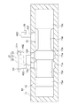
- FIG. 3 is a schematic cross-sectional view showing a configuration of a main part of a servo valve in the injection drive section of FIG. 2.
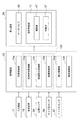
- the block diagram which shows the structure which concerns on the signal processing system of the die casting machine which concerns on embodiment.
- the figure explaining the operation of the injection apparatus which concerns on embodiment. 3 is a flowchart showing an example of a procedure of injection processing executed by the control device according to the embodiment.
- the timetable which shows operation
- movement of the some valve in the casting cycle which concerns on embodiment. 5 is a flowchart showing an example of a procedure of boosting/pressure holding processing executed by the control device according to the embodiment.
- FIG. 1 is a side view showing a configuration of a main part of a die casting machine 1 according to an embodiment of the present disclosure, a part of which includes a sectional view.
- the vertical direction of the paper is the vertical direction
- the horizontal direction of the paper and the penetrating direction of the paper are the horizontal directions.
- the die casting machine 1 injects an uncured metal material into the inside of a die 101 (a space such as a cavity Ca. The same applies hereinafter), and solidifies the metal material in the die 101 to obtain a die cast product (molded product). ) Is manufactured.
- the uncured state is, for example, a liquid or solid-liquid coexisting state.
- the solid-liquid coexisting state is a semi-solid state in which solidification proceeds from a liquid state, or a semi-molten state in which melting progresses from a solid state.
- the metal is, for example, aluminum or aluminum alloy.
- a molten metal (liquid metal material) is basically taken as an example of the uncured metal material.
- the mold 101 includes, for example, a fixed mold 103 and a movable mold 105.
- a fixed mold 103 and a movable mold 105 In the description of the present embodiment, for convenience, the cross section of the fixed mold 103 or the moving mold 105 is shown by one type of hatching, but these molds may be of a direct carving type or a nested type. It may be one. Further, a core or the like may be combined with the fixed mold 103 and the movable mold 105.
- the die casting machine 1 has, for example, a machine body 3 that performs a mechanical operation for molding, and a control unit 5 that controls the operation of the machine body 3.
- the machine body 3 includes, for example, a mold clamping device 7 that opens and closes the mold 101 and clamps the mold, an injection device 9 that injects molten metal into the mold 101, and a fixed mold 103 or a movable mold 105 (a die-cast product). In FIG. 1, it has an extruding device 11 for extruding from a movable die 105).
- the configuration other than the injection device 9 for example, the configuration of the mold clamping device 7 and the extrusion device 11
- the configuration other than the injection device 9 may be the same as various known configurations.
- the mold clamping device 7 moves the movable mold 105 toward the fixed mold 103 to close the mold. Further, the mold clamping device 7 applies a mold clamping force to the mold 101 according to the extension amount of the tie bar (reference numeral omitted) to perform mold clamping.
- a cavity Ca having the same shape as the molded product is formed in the mold 101 that has been clamped.
- the injection device 9 injects and fills the cavity Ca with the molten metal.
- the molten metal filled in the cavity Ca is deprived of heat by the mold 101, cooled, and solidified. As a result, a molded product is formed.
- the mold clamping device 7 moves the movable mold 105 in a direction away from the fixed mold 103 to open the mold. At this time, or after that, the extrusion device 11 extrudes the molded product from the moving mold 105.
- the control unit 5 includes, for example, a control device 13 (see FIG. 4) that performs various calculations and outputs a control command, an input device 17 that accepts an operator's input operation, and a display device 15 that displays an image. doing. Further, from another viewpoint, the control unit 5 includes, for example, a control panel (not shown) including a power supply circuit and a control circuit, and an operation unit 19 as a user interface.
- the control device 13 is provided, for example, on a control panel and an operation unit 19 (not shown).
- the control device 13 may be appropriately configured by being divided or dispersed.
- the control device 13 includes a lower-level control device for each of the mold clamping device 7, the injection device 9, and the extrusion device 11, and a higher-level control device that performs control such as synchronization between the lower-level control devices. It may be configured.
- the injection device 9 includes, for example, an injection sleeve 21 that communicates with the inside of the mold 101, a plunger 23 that can slide in the injection sleeve 21, and an injection drive unit 25 that drives the plunger 23.
- the mold 101 side may be referred to as the front and the opposite side may be referred to as the rear.
- the injection sleeve 21 is, for example, a cylindrical member connected to the fixed mold 103, and a supply port 21a for receiving the molten metal into the injection sleeve 21 is opened on the upper surface.
- the plunger 23 has, for example, a plunger tip 23a that can slide in the injection sleeve 21 in the front-rear direction, and a plunger rod 23b whose tip is fixed to the plunger tip.
- FIG. 2 is a schematic diagram showing the configuration of the injection drive unit 25 of the injection device 9.
- the injection drive unit 25 is, for example, of a hydraulic type, and has an injection cylinder 27 that drives the plunger 23 and a hydraulic device 29 that supplies hydraulic fluid (for example, oil) to the injection cylinder 27. ing.
- the injection cylinder 27 is configured by, for example, a so-called single-cylinder hydraulic cylinder. Specifically, for example, the injection cylinder 27 has a cylinder portion 31, a piston 33 that can slide inside the cylinder portion 31, and a piston rod 35 that is fixed to the piston 33 and extends from the cylinder portion 31. ing.
- the cylinder portion 31 is, for example, a cylindrical body having a circular internal cross-sectional shape.
- the inside of the cylinder portion 31 is partitioned by the piston 33 into a rod side chamber 31r on the side where the piston rod 35 extends and a head side chamber 31h on the opposite side.
- the piston 33 slides in the cylinder portion 31 in the front-rear direction.
- the injection cylinder 27 is arranged coaxially with the plunger 23. Then, as shown in FIG. 1, the tip of the piston rod 35 is connected to the rear end of the plunger 23 via a coupling (reference numeral omitted).
- the cylinder portion 31 is fixedly provided on a stationary portion of the die casting machine 1 (for example, a fixed die plate of the mold clamping device 7). Therefore, the plunger 23 moves forward or backward in the injection sleeve 21 by the movement of the piston 33 with respect to the cylinder portion 31.
- the hydraulic device 29 includes, for example, a tank 39 that stores hydraulic fluid, a pump 41 (hydraulic pressure source) that delivers hydraulic fluid, and an accumulator 43 (hydraulic pressure source) that stores high-pressure hydraulic fluid. And have.
- the tank 39, the pump 41, the accumulator 43, and the injection cylinder 27 are connected by a plurality of flow paths 45A to 45I (hereinafter, A to I may be omitted).
- the flow of the hydraulic fluid in the plurality of flow paths 45 is controlled by the plurality of valves (49, 51, 55, 57, 59 and 61).
- the tank 39 and the pump 41 are illustrated separately for convenience of illustration, but the pump 41 may send the hydraulic fluid stored in the tank 39. Further, for convenience of illustration, the tank 39 is shown in two places (one is omitted from the reference numeral), but in reality, the tank 39 may be integrated into one.
- the tank 39 is, for example, an open tank, and holds the hydraulic fluid under atmospheric pressure.
- the pressure of the hydraulic fluid in the tank 39 is called the tank pressure.
- the hydraulic fluid pressure In an open tank, the hydraulic fluid pressure is approximately equivalent to atmospheric pressure (ignoring the effect of the hydraulic fluid's own weight).
- the pump 41 is driven by an electric motor 47 (see FIG. 4) and delivers hydraulic fluid.
- the pump may be of an appropriate type such as a rotary pump, a plunger pump, a constant capacity pump, a variable capacity pump, a one-way pump, and a bidirectional (two-way) pump.
- the electric motor for driving the pump 41 may also be of an appropriate type such as a DC motor, an AC motor, an induction motor, a synchronous motor, or a servo motor.
- the pump 41 (electric motor) may be constantly driven during operation of the die casting machine 1 or may be driven as necessary.
- the plurality of flow paths 45 may be configured by pipes, hoses, and/or other members (for example, block-shaped members having through holes). Further, some of the plurality of flow paths 45 described below may be shared with each other.
- the connection relationship of the constituent elements (27, 39, 41 and 43) of the hydraulic device 29 by the plurality of flow paths 45 and the plurality of valves is as follows, for example.
- the accumulator 43 and the head side chamber 31h are connected via a flow path 45B.
- the hydraulic fluid is supplied from the accumulator 43 to the head side chamber 31h, and the piston 33 advances.
- the flow path 45B is provided with an ACC valve 51 that allows and prohibits the supply of the hydraulic fluid from the accumulator 43 to the head side chamber 31h.
- the configuration of the ACC valve 51 may be any suitable one.
- the ACC valve 51 is composed of a pilot type check valve. This check valve prohibits the flow from the accumulator 43 to the head side chamber 31h when the pilot pressure is not introduced, and allows the flow in the opposite direction, and when the pilot pressure is introduced, both Allow the flow.
- the rod side chamber 31r and the tank 39 can be connected to each other via a flow channel 45C connected to the rod side chamber 31r and a flow channel 45D connected to the tank 39. Thereby, for example, when the piston 33 moves forward, the hydraulic fluid can be discharged from the rod side chamber 31r to the tank 39.
- the rod-side chamber 31r and the head-side chamber 31h can be connected to each other via the flow channel 45C and the flow channel 45E connected to the head-side chamber 31h.
- the hydraulic fluid discharged from the rod-side chamber 31r as the piston 33 moves forward can flow into the head-side chamber 31h.
- the hydraulic fluid required when the piston 33 is moved forward can be reduced.
- the flow paths 45C and 45E form the run-around circuit 53.
- a servo valve 55 is interposed between the flow paths 45C to 45E.
- the servo valve 55 is represented by the symbol of the 3-port 3-position switching valve, the connection relationship of the flow paths 45C, 45D and 45E is switched by the servo valve 55. Specifically, for example, at the central position of the three illustrated rectangles, the flow paths 45C, 45D, and 45E are blocked from each other. At the position on the left side of the drawing, the flow passage 45C (rod side chamber 31r) and the flow passage 45D (tank 39) are connected, and the flow passage 45C and the flow passage 45E (head side chamber) are shut off (runaround circuit 53). Is turned off.).
- the servo valve 55 is configured to control the flow rate of the hydraulic fluid from the flow passage 45C (rod side chamber 31r) to the flow passage 45D (tank 39) or the flow passage 45E (head side chamber 31h), and also as a flow control valve. Function. By controlling this flow rate, for example, the forward speed of the piston 33 is controlled. That is, the servo valve 55 constitutes a so-called meter-out circuit.
- the servo valve 55 is composed of, for example, a flow rate adjusting valve with pressure compensation that can keep the flow rate constant even if the pressure fluctuates. Further, as its name implies, the servo valve 55 is a servo valve which is used in a servo mechanism and can modulate the flow rate steplessly (continuously to an arbitrary value) according to an input signal.
- the configuration for driving the valve body (described later) of the servo valve 55 may be appropriate, and various known configurations may be applied.
- the drive system may be an electro-hydraulic type or an electric type.
- electro-hydraulic type displacement of a solenoid (motor) according to an input electric signal is converted into pilot pressure by a pre-stage amplifier such as a nozzle flapper, and the pilot pressure drives a valve element.
- electric type for example, the displacement of the solenoid according to the input electric signal is transmitted to the valve body without hydraulic pressure.
- the valve body may be urged by a spring so as to be positioned at a predetermined position when a driving force by electricity or hydraulic pressure is not applied.
- the configuration for outputting a signal (feedback signal) according to the position of the valve element of the servo valve 55 may be appropriate, and various known configurations may be applied.
- a differential transformer may be used.
- the flow path 45E is provided with a check valve 56 that allows the flow from the servo valve 55 to the head side chamber 31h and prohibits the flow in the opposite direction. Thereby, for example, backflow from the head side chamber 31h to the rod side chamber 31r is prevented.
- the pump 41 and the rod side chamber 31r can be connected to each other via a flow channel 45F connected to the pump 41 and a flow channel 45G connected to the rod side chamber 31r.
- the hydraulic fluid can be supplied from the pump 41 to the rod side chamber 31r to retract the piston 33.
- the head-side chamber 31h and the tank 39 can be connected to each other via a flow passage 45H connected to the head-side chamber 31h and a flow passage 45I connected to the tank 39. Thereby, for example, when the piston 33 retracts, the hydraulic fluid can be discharged from the head side chamber 31h to the tank 39.
- the pump 41 and the head side chamber 31h can be connected to each other via the above-mentioned flow path 45F and the above-mentioned flow path 45H.
- the hydraulic fluid can be supplied from the pump 41 to the head side chamber 31h, and the piston 33 can be moved forward.
- a switching valve 57 is interposed between the flow paths 45F to 45I.
- the switching valve 57 is represented by the symbol of the 4-port 3-position switching valve, and the connection relationship of the flow paths 45F to 45I is switched by the switching valve 57.
- the flow path 45G rod side chamber 31r
- the flow path 45H head side chamber 31h
- the flow path 45I tunnel 39
- the flow channel 45F (pump 41) and the flow channel 45G (rod side chamber 31r) are connected, and the flow channel 45H (head side chamber) and the flow channel 45I (tank 39) are connected. Thereby, for example, the piston 33 can be retracted.
- the flow passage 45F (pump 41) and the flow passage 45H (head side chamber 31h) are connected, and the flow passage 45G (rod side chamber 31r) and the flow passage 45I (tank 39) are connected. Thereby, for example, the piston 33 can be moved forward.
- the switching valve 57 does not have to contribute to the discharge of the hydraulic fluid from the rod side chamber 31r to the tank 39.
- the flow path 45G is provided with a check valve 59 that allows the flow from the switching valve 57 to the rod side chamber 31r and prohibits the flow in the opposite direction. Accordingly, for example, when the servo valve 55 controls the flow rate of the hydraulic fluid discharged from the rod side chamber 31r, the flow from the rod side chamber 31r to the switching valve 57 can be prohibited.
- FIG. 3 is a schematic cross-sectional view showing the configuration of the main part of the servo valve 55.
- the portion of the servo valve 55 that directly controls the flow between the head-side chamber 31h, the rod-side chamber 31r, and the tank 39 is schematically shown. Therefore, for example, illustrations of a portion related to driving the solenoid, the pilot flow path and/or the spring, a portion related to generation of a feedback signal such as a differential transformer, and a portion defining a drive limit of the valve body are omitted. There is.
- the opening position of the port 75 on the inner surface of the valve sleeve 71 and the opening position on the outer surface of the valve sleeve 71 are substantially the same. However, depending on the shape of the valve sleeve 71, it is possible to shift the opening position on the outer surface from the opening position on the inner surface.
- the small diameter portion faces the two ports 75, so that the two ports 75 communicate with each other. Further, since the large diameter portion faces any one port 75, that one port 75 is cut off from the other port 75. Further, the large diameter portion is located between any two ports, so that the two ports 75 are cut off from each other. In the illustrated example, specifically, it is as follows.
- the small diameter portion 73d faces the head-side port 75H (for example, the whole).
- the small diameter portion 73e faces the tank side port 75T (for example, the whole).
- the large diameter portions 73a and 73c on both sides contribute to separating the small diameter portions 73d and 73e from both ends of the valve sleeve 71.
- both ends of the valve sleeve 71 are used to provide a drive unit for driving the spool 73.
- the small diameter portion 73d on the left side gradually increases the area facing the rod side port 75R while maintaining the state of facing the entire head side port 75H. ..
- a change in the degree of opening for controlling the flow rate of the hydraulic fluid flowing between the head side port 75H and the rod side port 75R is realized.
- the small diameter portion 73d can be moved to a position facing the entire rod-side port 75R while facing the entire head-side port 75H, for example. At this time, the opening degree is maximized.
- the cutoff between the rod side port 75R and the tank side port 75T is maintained by interposing a large diameter portion 73b between them.
- the large diameter portion 73b may face a part or all of the tank side port 75T when the spool 73 moves to the above position.
- FIG. 4 is a block diagram showing the configuration of the signal processing system of the die casting machine 1.
- the control device 13 is composed of, for example, a computer including a CPU, a RAM, a ROM, and an external storage device, although not particularly shown.
- a plurality of functional units 13a to 13f responsible for various controls and calculations are constructed.
- the plurality of functional units include, for example, a preparation control unit 13a, a low-speed injection control unit 13b, a high-speed injection control unit 13c, a deceleration control unit 13d, a boost control unit 13e, and a pressure holding control unit 13f.
- the low-speed injection control unit 13b and the high-speed injection control unit 13c (and the deceleration control unit 13d) may be collectively referred to as an injection control unit 13h. Details of the control and the like performed by these plurality of functional units will be described later in the description of the operation (FIG. 6 and the like).
- the hydraulic pressure device 29 may be considered to include the hydraulic pressure supply unit 77.
- the hydraulic pressure supply unit 77 includes a pump 41 (FIG. 2), an electric motor 47, a switching valve 57, and a control valve 61, and supplies hydraulic fluid to the head side chamber 31h and the rod side chamber 31r. The operation is controlled by the control device 13.
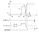
- FIG. 5 is a diagram for explaining the operation of the injection device 9.
- the upper part of FIG. 5 is a graph showing changes with time of the injection speed (speed of the plunger 23) and the injection pressure (pressure applied by the plunger 23 to the molten metal).
- the lower part of FIG. 5 is a timing chart showing the operation of the ACC valve 51, the servo valve 55, and the hydraulic pressure supply unit 77.
- the horizontal axis t indicates time.
- the vertical axis represents the magnitude of the injection speed V and the injection pressure P.
- the line Lv shows the change in injection speed.
- the line Lp shows the change in injection pressure.
- the line in the item of "ACC valve” in FIG. 5 means that the pilot pressure is introduced into the ACC valve 51 when it is in the "open” position, and when it is in the "closed” position, it means that the pilot pressure is introduced into the ACC valve 51. This means that the pilot pressure is not introduced into the valve 51. In the illustrated range, the pilot pressure is introduced into the ACC valve 51 at time 0, and then the pilot pressure is continuously introduced.
- the solid line in the item of "servo valve" in FIG. 5 is located at the central position of the symbol in FIG. 2 (the position where the flow from the rod side chamber 31r to the head side chamber 31h and the tank 39 is prohibited) when the position is shown by the dotted line. Means there is. Further, when the solid line is above the dotted line (position “R ⁇ H”), it is located on the right side of the symbol in FIG. 2 (position allowing the flow from the rod side chamber 31r to the head side chamber 31h). Means that. Further, when the solid line is below the dotted line (position “R ⁇ T”), it is located on the left side of the symbol in FIG. 2 (position allowing flow from the rod side chamber 31r to the tank 39). Means Further, the solid line means that the opening degree (the flow rate from another viewpoint) increases as the distance from the dotted line increases.
- the injection device 9 has a low-speed injection process (time points t0 to t1), a high-speed injection process (time points t1 to t2), a deceleration process (time points t2 to t3), and a pressurization (pressure increase) process (time points) for each casting cycle.
- t3 to t5) and the pressure-holding step (time t5 to) are sequentially performed.
- the high-speed injection process (time points t1 to t2) is a process of advancing the plunger 23 at a high-speed injection speed V H higher than the low-speed injection speed V L , following the low-speed injection process.
- V H The specific value of the high-speed injection speed V H may be appropriately set by operating the input device 17, and is, for example, 1 m/s or more.
- the deceleration process (time points t2 to t3) is a process of reducing the speed of the plunger 23.
- the speed of the plunger 23 By controlling the speed of the plunger 23 to be reduced, for example, the impact (surge pressure) generated when the molten metal is filled in the cavity Ca can be reduced.
- the pressurizing step (time points t3 to t5) is a step of increasing the pressure applied to the molten metal by the plunger 23 so that the pressure of the molten metal reaches a predetermined casting pressure Pe.
- the pressure holding step (time point t5 or more) is a step of maintaining the casting pressure Pe and waiting for the molten metal to solidify. By increasing the pressure of the molten metal and waiting for solidification, for example, porosity and/or sink marks can be reduced.
- the specific value of the casting pressure Pe may be appropriately set by operating the input device 17.
- the ACC valve 51 is opened, for example, by introducing a pilot pressure from the low-speed injection process to the pressure-holding process. As a result, hydraulic fluid is supplied from the accumulator 43 to the head-side chamber 31h, and a forward force is applied to the piston 33. As a result, the above various steps can be performed.
- the operation of the servo valve 55 realizes the switching of the above various processes. Specifically, switching from the low-speed injection process to the high-speed injection process (time point t1), switching from the high-speed injection process to the deceleration process (time point t2), switching from the deceleration process to the boosting process (time point t3), from the boosting process The switching to the pressure holding process (time t5) is realized.
- “C” indicates that the servo valve 55 is at the center position of the symbol in FIG. 2 (the flow from the rod side chamber 31r to the head side chamber 31h and the tank 39 is prohibited). It is shown that. “R ⁇ H” indicates that the servo valve 55 is located on the right side of the symbol in FIG. 2 (the flow from the rod side chamber 31r to the head side chamber 31h is allowed). “R ⁇ T” indicates that the servo valve 55 is located on the left side of the symbol in FIG. 2 (flow from the rod side chamber 31r to the tank 39 is allowed).
- control valve column "-" indicates that no pilot pressure has been introduced into the control valve 61 ((flow from the head side chamber 31h to the switching valve 57 is prohibited)). Indicates that the pilot pressure is introduced into the control valve 61 (the flow from the head side chamber 31h to the switching valve 57 is allowed).
- “C” indicates that the switching valve 57 is in the central position of the symbol in FIG. 2 (the flow from the pump 41 to the rod side chamber 31r and the head side chamber 31h is prohibited). ing. “P ⁇ R” indicates that the switching valve 57 is located on the left side of FIG. 2 (flow from the pump 41 to the rod side chamber 31r is allowed). “P ⁇ H” indicates that the servo valve 55 is located on the right side of the symbol in FIG. 2 (the flow from the pump 41 to the head side chamber 31h is allowed).
- a preparatory step is performed before the injection is started (before the time point t0 in FIG. 5).
- the injection device 9 Before the start of this preparation step, the injection device 9 is in the state shown in FIGS. 1 and 2. That is, the plunger 23 (piston 33) is located at the backward limit.
- the hydraulic device 29 is in an appropriate state in which the piston 33 can be positioned at the backward limit.
- the pilot pressure is not introduced into the ACC valve 51 and the control valve 61, the servo valve 55 is closed (the central position in FIG. 2), and the switching valve 57 shuts off the pump 41 from the injection cylinder 27. doing.
- the control device 13 switches the switching valve 57 to the position on the left side in FIG. 2, supplies the hydraulic pressure from the pump 41 to the rod side chamber 31r, and changes the pressure in the rod side chamber 31r. To raise. This reduces the probability of so-called jumping occurring at the start of injection (time t0). Specifically, it is as follows.
- the speed thereof is controlled by the flow rate of the working fluid discharged from the rod side chamber 31r, as described above.
- the speed of the piston 33 is uniquely determined by the flow rate of the hydraulic fluid discharged from the rod side chamber 31r.
- the speed of the piston 33 is faster than the speed determined by the flow rate of the hydraulic fluid discharged from the rod side chamber 31r. Become. That is, jumping occurs.
- the control device 13 determines, for example, whether or not the pressure detected by the rod pressure sensor 69 has reached a predetermined set pressure. Then, the preparation control unit 13a continues to apply the hydraulic pressure from the pump 41 to the rod side chamber 31r during the negative determination. Then, when an affirmative determination is made, the control device 13 proceeds to the next step.
- the set pressure may be, for example, the maximum pressure that can be applied from the pump 41 to the rod side chamber 31r (a constant pressure that is reached when the hydraulic pressure is applied from the pump 41 to the rod side chamber 31r in a sufficient time). The pressure may be lower or lower than this.
- step ST3 of FIG. 6 and row “2” of FIG. 7 when the predetermined low-speed injection start condition is satisfied, the control device 13 (preparation control unit 13a) sets the switching valve 57 to the center of FIG. By switching to the position, the supply of the hydraulic fluid from the pump 41 to the rod side chamber 31r is stopped, and the preparation process is completed.
- the control device 13 low-speed injection control unit 13b
- the low-speed injection control unit 13b switches the servo valve 55 to the position on the left side in FIG. 2 and turns on the runaround circuit 53. As a result, the piston 33 (plunger 23) moves forward. That is, the low speed injection process is started.
- the rod side chamber 31r and the head side chamber 31h are connected by the runaround circuit 53, theoretically the same pressure is obtained.
- the pressure receiving area of the piston 33 in the rod side chamber 31r is smaller than the pressure receiving area of the piston 33 in the head side chamber 31h by the area of the cross section of the piston rod 35. Therefore, the force received by the piston 33 from the head side chamber 31h is larger than the force received by the piston 33 from the rod side chamber 31r, and the piston 33 advances. At this time, the hydraulic fluid discharged from the rod side chamber 31r flows into the head side chamber 31h.
- the above-mentioned low-speed injection start condition is, for example, that the fixing of the fixed mold 103 and the moving mold 105 is completed, the molten metal is supplied to the injection sleeve 21, and an affirmative determination is made in the above-mentioned step ST2. Including that.
- the operation of the die casting machine 1 may be set such that either the completion of the supply of the molten metal to the injection sleeve 21 or the positive determination in step ST2 is satisfied first.
- the speed of the plunger 23 is controlled by adjusting the opening degree of the servo valve 55.
- the control device 13 feedback-controls the opening degree of the servo valve 55 based on the detection value of the position sensor 65.
- This feedback control may be a normal speed feedback control based on the deviation of the speed itself of the plunger 23, or a position feedback based on the deviation between the target position and the current position, which is updated every moment at a predetermined time interval. It may be the speed feedback control realized by the control.
- the high-speed injection control unit 13c increases the opening degree of the servo valve 55 related to the flow from the rod side chamber 31r to the head side chamber 31h, as shown in the vicinity of time point t1 in FIG. Increase the flow rate associated with the flow. Further, the high-speed injection control unit 13c, following the low-speed injection process, feedback-controls the opening degree of the servo valve 55 based on the detection value of the position sensor 65. This speed feedback control may be based on the deviation of the speed itself, or may be realized by position feedback control, as in the low speed injection process.
- the high-speed injection start position may be appropriately set based on the operation on the input device 17.
- the high speed injection control unit 13c determines whether the plunger 23 reaches the high speed injection start position based on the position of the plunger 23 detected by the position sensor 65, for example.
- the target speed is changed when it is determined that it has reached. Further, in the case where the speed feedback control is substantially performed by the position feedback control for the target position which is updated every moment after the low speed injection process to the high speed injection process, for example, the target from the low speed injection process to the high speed injection process.
- the speed of the plunger 23 is switched when the plunger 23 reaches the high-speed injection start position. In other words, it is not determined whether the plunger 23 has reached the high-speed injection start position.
- the deceleration control unit 13d reduces the opening degree related to the flow from the rod side chamber 31r to the head side chamber 31h in the servo valve 55 as shown near the time point t2 in FIG. Reduce the flow rate related to. Further, the deceleration control unit 13d feedback-controls the opening degree of the servo valve 55 based on the detection value of the position sensor 65 subsequent to the high-speed injection process. This speed feedback control may be based on the deviation of the speed itself or may be realized by position feedback, as in the low speed injection process and the high speed injection process.
- the deceleration control unit 13d determines whether or not the plunger 23 has reached the deceleration start position based on the position of the plunger 23 detected by the position sensor 65, for example.
- the target speed is changed when it is determined that it has reached.
- the speed feedback control is substantially performed by the position feedback control for the target position which is updated every moment after the high speed injection process to the deceleration process, for example, the target position from the high speed injection process to the deceleration process
- the speed of the plunger 23 is switched when the plunger 23 reaches the deceleration start position. In other words, it is not determined whether the plunger 23 has reached the deceleration start position.
- the deceleration start position may be appropriately set based on, for example, an operation on the input device 17.
- the molten metal fills the cavity Ca to some extent, the molten metal loses its place of departure, and the plunger 23 is rapidly decelerated by receiving a reaction force from the filled molten metal.
- the deceleration start position may be appropriately set so as to alleviate the impact when such a sudden deceleration is started.
- the start of deceleration and/or the velocity gradient may be greatly affected by both the control of the servo valve 55 as described above and the reaction force from the molten metal.
- step ST8 of FIG. 6 and row “5” of FIG. 7 As shown in step ST8 of FIG. 6 and row “5” of FIG. 7, when a predetermined boosting start condition is satisfied, the control device 13 (boosting control unit 13e) starts boosting control for increasing the injection pressure. ..
- the control device 13 switches the position of the servo valve 55 to the position on the left side in FIG. ,
- the destination of the hydraulic fluid from the rod side chamber 31r is switched from the head side chamber 31h to the tank 39.
- the pressure in the rod-side chamber 31r is theoretically set to a tank pressure lower than that of the pressure in the head-side chamber 31h.
- the pressure applied to the molten metal by the plunger 23 can be easily increased.
- the plunger 23 substantially stops (time point t4).
- the above boost start conditions may be set appropriately.
- the conditions for starting boosting are that the injection pressure based on the detection values of the rod pressure sensor 69 and the head pressure sensor 67 has reached a predetermined set pressure, and that the detection value of the head pressure sensor 67 has reached a predetermined set pressure.
- the boosting start condition (setting of set pressure or set position, etc.) may be set, for example, by operating the input device 17.
- the opening degree of the servo valve 55 during boosting may be set and controlled appropriately.
- the boost control unit 13e is a servo valve based on the injection pressure obtained from the detected values of the rod pressure sensor 69 and the head pressure sensor 67 so that a desired boost curve set by the operation on the input device 17 can be obtained.
- Feedback control of the opening degree of 55 may be performed. More specifically, for example, feedback control may be performed so that the detected value of the injection pressure converges to a target pressure that is updated from moment to moment at predetermined time intervals. Further, the opening degree of the servo valve 55 during boosting may be simply maintained at a constant value (for example, maximum value) without performing feedback control based on the injection pressure.
- the servo valve 55 is switched to the central position in FIG. 2 in the process in which the pressure in the rod side chamber 31r approaches the tank pressure, prohibiting the discharge of the hydraulic fluid from the rod side chamber 31r and performing any casting.
- the operation when realizing the pressure Pe is shown.
- This switching may be performed when an appropriate boosting completion condition is satisfied.
- the pressure increase completion condition may be set when the injection pressure based on the detection values of the rod pressure sensor 69 and the head pressure sensor 67 reaches a predetermined set pressure.
- the set pressure may be the casting pressure Pe, or may be a pressure obtained by adding or subtracting a correction amount considering the fluctuation of the injection pressure after the servo valve 55 is closed to the casting pressure Pe.
- the completion of the boosting process may be a predetermined time after the boosting process is started.
- the flow from the rod-side chamber 31r to the tank 39 may be allowed during the pressurizing process and the pressure-holding process, and the pressure of the rod-side chamber 31r may be controlled to be the tank pressure.
- the pressure of the rod side chamber 31r is not used as the tank pressure is mainly taken as an example.
- the control device 13 pressure-holding control unit 13f
- the holding pressure control unit 13f basically controls the boosting step.
- the various valves are controlled by the servo valve 55 so as to maintain the state in which the discharge of the hydraulic fluid from the rod side chamber 31r is prohibited. This theoretically maintains the casting pressure Pe.
- the pressure holding control unit 13f performs a process for ending the pressure holding.
- the holding pressure control unit 13f may stop the introduction of the pilot pressure into the ACC valve 51 and stop the supply of the hydraulic pressure from the accumulator 43 to the head side chamber 31h.
- the pressure holding control unit 13f may introduce pilot pressure into the control valve 61 to allow the flow of the hydraulic fluid from the head side chamber 31h to the tank 39 and set the head side chamber 31h as the tank pressure.
- the servo valve 55 may allow the flow of the hydraulic fluid from the rod-side chamber 31r to the tank 39 to set the rod-side chamber 31r to the tank pressure.
- the control device 13 causes the mold clamping device 7 to open the mold and causes the extrusion device 11 to push out the molded product from the fixed mold 103.
- the control device 13 controls the hydraulic device 29 so that the injection cylinder 27 produces a driving force for pushing the biscuit by the plunger 23.
- This extrusion may be realized by an operation similar to the operation in the pressurization process (the pressure of the accumulator 43 from another viewpoint), or the operation of the row of “8” in FIG. 7 described later (from another viewpoint of the pump 41). Pressure).
- the control device 13 retracts the plunger 23 to the initial position. Specifically, as shown in the row “7” of FIG. 7, the servo valve 55 is switched to the central position of FIG. 2 to prohibit the discharge of the hydraulic fluid from the rod side chamber 31r. Pilot pressure is not introduced to the ACC valve 51, and the supply of hydraulic fluid from the accumulator 43 to the head side chamber 31h is prohibited. The pilot pressure is introduced into the control valve 61 to allow the flow from the head side chamber 31h to the switching valve 57. The switching valve 57 is switched to the position on the left side in FIG. 2, and allows the flow from the pump 41 to the rod side chamber 31r and the flow from the head side chamber 31h to the tank 39. Therefore, the piston 33 retracts due to the pressure of the pump 41.
- control device 13 supplies the hydraulic fluid from the pump 41 to the accumulator 43 at an appropriate time to accumulate the pressure of the accumulator 43.
- the electric motor 47 is driven in a state where the pilot pressure is not introduced into the ACC valve 51 and the switching valve 57 prohibits the supply of the hydraulic fluid from the pump 41 to the injection cylinder 27.
- the hydraulic fluid is supplied from the pump 41 to the accumulator 43 via the flow path 45A.
- the injection device 9 can also supply the hydraulic fluid from the pump 41 to the head side chamber 31h to advance the piston 33. This operation is performed, for example, when performing a predetermined operation on the input device 17 to move the piston 33 forward, separately from the casting cycle.
- the servo valve 55 is switched to the position on the left side in FIG. 2 to allow the hydraulic fluid to be discharged from the rod side chamber 31r to the tank 39. Pilot pressure is not introduced to the ACC valve 51, and the supply of hydraulic fluid from the accumulator 43 to the head side chamber 31h is prohibited.
- the control valve 61 may or may not have the pilot pressure introduced therein, and in any case allows the flow from the switching valve 57 to the head side chamber 31h.
- the switching valve 57 is switched to the position on the right side of FIG. 2 to allow the flow from the pump 41 to the head concubine 31h.
- the hydraulic fluid in the rod side chamber 31r is discharged to the tank 39 via the servo valve 55, but may be discharged to the head side chamber 31h via the servo valve 55. Further, the check valve 59 may be opened by the pilot pressure, and the hydraulic fluid may be discharged from the rod side chamber 31r to the tank 39 via the check valve 59 and the switching valve 57.
- FIG. 8 is a flowchart showing an example of the procedure of the pressure increasing/pressure maintaining process executed by the controller 13 in the pressure increasing process and the pressure maintaining process.
- Steps ST21 to ST23 correspond to the step-up process.
- the control device 13 step-up control unit 13e
- the control device 13 boosting control unit 13e
- FIG. 8 exemplifies the determination as to whether or not the injection pressure based on the detection values of the rod pressure sensor 69 and the head pressure sensor 67 has reached the casting pressure Pe as the pressure increase completion condition.
- the control device 13 continues the boosting when the determination is negative, and proceeds to step ST23 when the determination is positive.
- the servo valve 55 is switched to the central position in FIG. 2, the discharge of the hydraulic fluid from the rod side chamber 31r is prohibited, and the boosting step is completed. From another point of view, the pressure holding process is started.
- the pressure holding step basically, the hydraulic pressure is continuously applied from the accumulator 43 to the head side chamber 31h, and the discharge of the hydraulic fluid from the rod side chamber 31r is prohibited. Therefore, theoretically, the casting pressure Pe realized by the pressure of the accumulator 43 and the pressure of the rod side chamber 31r when the discharge of the hydraulic fluid from the rod side chamber 31r by the servo valve 55 is prohibited is maintained.
- the pressure applied from the plunger 23 to the molten metal may fluctuate during holding the pressure due to leakage of the hydraulic fluid.
- the injection pressure rises and becomes higher than the casting pressure Pe.
- the injection pressure decreases and becomes lower than the casting pressure Pe. Therefore, as shown in steps ST24 to ST27, a process of supplying the hydraulic fluid from the pump 41 to the rod side chamber 31r or the head side chamber 31h may be performed.
- step ST24 the control device 13 (holding pressure control unit 13f) determines whether or not the detection value of the injection pressure based on the detection values of the rod pressure sensor 69 and the head pressure sensor 67 exceeds a predetermined allowable upper limit. Then, the holding pressure control unit 13f proceeds to step ST25 when the determination is affirmative, and proceeds to step ST26 when the determination is negative.
- the allowable upper limit is a pressure higher than the casting pressure Pe, and may be set by operating the input device 17, or may be set by the holding pressure control unit 13f based on the casting pressure Pe.
- step ST25 the holding pressure control unit 13f temporarily applies the hydraulic pressure of the pump 41 to the rod side chamber 31r, and controls the hydraulic pressure supply unit 77 to increase the pressure of the rod side chamber 31r. As a result, the injection pressure is reduced. More specifically, the pressure holding control unit 13f switches the switching valve 57 to the position on the left side of FIG. 2 as shown in the parentheses in the line “6” of FIG. 7, and moves from the pump 41 to the rod side chamber 31r. Allow the flow of.
- the flow passage 45H connected to the head side chamber 31h and the tank 39 are connected by the switching valve 57, but the control valve 61 in which the pilot pressure is not introduced is used to discharge the hydraulic fluid from the head side chamber 31h to the tank 39. Prohibited by
- the operation of increasing the pressure of the rod side chamber 31r may be performed, for example, for a predetermined time, or may be performed until the detection value of the injection pressure satisfies a predetermined condition.
- the predetermined condition may be that the detected value of the injection pressure is less than the allowable upper limit, or the detected value of the injection pressure is lowered to the casting pressure Pe (or the pressure in which a predetermined correction amount is added). May be that.
- the pressure-holding control unit 13f After maintaining the pressure in the rod-side chamber 31r, the pressure-holding control unit 13f returns the switching valve 57 to the central position in FIG. 2 (the position where the flow from the pump 41 to the injection cylinder 27 is prohibited), and proceeds to step ST28. ..
- step ST26 the holding pressure control unit 13f determines whether or not the detection value of the injection pressure based on the detection values of the rod pressure sensor 69 and the head pressure sensor 67 is below a predetermined lower limit. Then, the holding pressure control unit 13f proceeds to step ST27 when the determination is affirmative, and proceeds to step ST28 when the determination is negative.
- the allowable lower limit is a pressure smaller than the casting pressure Pe and may be set by an operation on the input device 17, or may be set by the holding pressure control unit 13f based on the casting pressure Pe.
- step ST27 the holding pressure control unit 13f temporarily applies the hydraulic pressure of the pump 41 to the head side chamber 31h, and controls the hydraulic pressure supply unit 77 to increase the pressure of the head side chamber 31h.
- the injection pressure increases. More specifically, the holding pressure control unit 13f switches the switching valve 57 to the position on the right side in FIG. 2 as shown in the parentheses in the row of “6” in FIG. 7, and the pump 41 to the head side chamber 31h( Allows flow to the accumulator 43).
- the flow passage 45G connected to the rod-side chamber 31r and the tank 39 are connected by the switching valve 57, but the discharge of the hydraulic fluid from the rod-side chamber 31r to the tank 39 is prohibited by the check valve 59.
- the operation of increasing the pressure of the head side chamber 31h may be performed, for example, for a predetermined time, or may be performed until the detected value of the injection pressure satisfies a predetermined condition.
- the predetermined condition may be that the detected value of the injection pressure exceeds the allowable lower limit, or the detected value of the injection pressure rises to the casting pressure Pe (or a pressure in which a predetermined correction amount is added thereto). It may be that.
- the pressure-holding control unit 13f After increasing the pressure in the head-side chamber 31h, the pressure-holding control unit 13f returns the switching valve 57 to the central position in FIG. 2 (the position where the flow from the pump 41 to the injection cylinder 27 is prohibited), and proceeds to step ST28. ..
- step ST28 the pressure holding control unit 13f determines whether or not the pressure holding end condition is satisfied. If the determination is negative, the process returns to step ST24, and if the determination is positive, the pressure holding is ended.
- the pressure holding end condition may be, for example, that a predetermined time (for example, a time sufficient for the molten metal to solidify) has elapsed from a predetermined time (for example, the start time of the pressure holding process).
- the injection device 9 includes the injection cylinder 27, the runaround circuit 53, the tank 39, and the servo valve 55.
- the injection cylinder 27 drives a plunger 23 that pushes the molding material into the mold 101.
- the run-around circuit 53 causes the hydraulic fluid discharged from the rod-side chamber 31r as the piston 33 of the injection cylinder 27 advances to flow into the head-side chamber 31h.
- the tank 39 receives the hydraulic fluid discharged from the rod side chamber 31r as the piston 33 moves forward.
- the servo valve 55 is provided in the runaround circuit 53 and is connected to the tank 39. The servo valve 55 can be switched between the first state (the position on the right side in FIG. 2) and the second state (the position on the left side in FIG. 2).
- the servo valve 55 In the first state, the servo valve 55 allows the flow from the rod side chamber 31r to the head side chamber 31h, but prohibits the flow from the rod side chamber 31r to the tank 39. In the second state, the servo valve 55 allows the flow from the rod side chamber 31r to the tank 39 while inhibiting the flow from the rod side chamber 31r to the head side chamber 31h. Moreover, the servo valve 55 can control the flow rate of the hydraulic fluid discharged from the rod side chamber 31r in each of the first state and the second state.
- one servo valve 55 realizes ON/OFF of the run-around circuit 53, communication between the rod-side chamber 31r and the tank 39 and interruption, and control of the flow rate of the hydraulic fluid discharged from the rod-side chamber 31r.
- simplification of the configuration, simplification of control, smooth switching between processes (for example, switching from the deceleration process to the boosting process), and/or cost reduction are expected.
- the servo valve 55 has the third state (the central position in FIG. 2) in which the first state, the second state, and the flow from the rod side chamber 31r to the head side chamber 31h and the tank 39 are prohibited. ) And can be switched.
- the operations that can be realized by the servo valve 55 are increased, and the simplification effect described above is improved.
- the servo valve 55 can be used for prohibiting the discharge of the hydraulic fluid from the rod side chamber 31r in the process of lowering the pressure of the rod side chamber 31r in the pressurization process and realizing an arbitrary casting pressure Pe.
- the servo valve 55 has a hollow valve body (valve sleeve 71) and a valve body (spool 73) movable in the valve sleeve 71.
- the valve sleeve 71 has a rod side port 75R that communicates with the rod side chamber 31r, a head side port 75H that communicates with the head side chamber 31h, and a tank side port 75T that communicates with the tank 39.
- the spool 73 connects the rod-side port 75R and the head-side port 75H and blocks the rod-side port 75R and the tank-side port 75T, and the rod-side port 75R and the head-side port 75H. It is movable between a position where the port 75R and the tank-side port 75T communicate with each other.
- the servo valve 55 is a spool valve having a valve sleeve 71 as a valve body and a spool 73 as a valve body.
- the rod-side port 75R, the head-side port 75H, and the tank-side port 75T are open on the inner peripheral surface around the axis of the valve sleeve 71.
- the spool 73 slides in the valve sleeve 71 in the axial direction.
- the head side port 75H is located on one side (left side in FIG. 3) of the spool 73 in the moving direction with respect to the rod side port 75R.
- the tank side port 75T is located on the other side (right side in FIG.
- the spool 73 has a large diameter portion 73b and small diameter portions 73d and 73e.
- the large diameter portion 73b has a diameter that slides with respect to the valve sleeve 71, and can block the entire rod-side port 75R.
- the small diameter portion 73d is located on the one side (left side in FIG. 3) with respect to the large diameter portion 73b, has a smaller diameter than the large diameter portion 73b, and faces the rod side port 75R and the head side port 75H.
- the two can communicate with each other.
- the small diameter portion 73e is located on the other side (right side in FIG. 3) of the large diameter portion 73b, has a smaller diameter than the large diameter portion 73b, and faces the rod side port 75R and the tank side port 75T. The two can communicate with each other.
- two destinations of the hydraulic fluid that have flowed into the valve sleeve 71 from the rod side port 75R are both adjacent to the rod side port 75R.
- the configuration can be simplified and the destination of the hydraulic fluid can be switched quickly.
- one small diameter that connects the rod side port 75R and another port is provided between the two large diameter portions that can close the head side port 75H and the tank side port 75T.
- a large diameter portion that regulates the flow of the hydraulic fluid acts directly on the rod-side port 75R as compared to a mode in which the portion is provided (the embodiment is also included in the technique according to the present disclosure). As a result, for example, it is expected that the accuracy of the flow rate control of the hydraulic fluid discharged from the rod side chamber 31r will be improved.
- the injection device 9 has a check valve 56.
- the check valve 56 is located between the head side chamber 31h and the servo valve 55 in the runaround circuit 53, prohibits the flow from the head side chamber 31h to the servo valve 55, and moves from the servo valve 55 to the head side chamber 31h. Allow the flow of.
- the injection device 9 has an injection control unit 13h and a boost control unit 13e.
- the injection control unit 13h controls the servo valve 55 so as to be in the first state (the state in which the runaround circuit 53 is turned on) at least during the periods of the low speed injection process and the high speed injection process.
- the boost controller 13e controls the servo valve 55 so as to be in the second state (a state in which the flow from the rod side chamber 31r to the tank 39 is allowed) at least during the boost step.
- the required amount of the hydraulic fluid can be reduced by the run-around circuit 53 in the low-speed injection process and the high-speed injection process in which the moving distance of the piston 33 is relatively long.
- the pressure difference between the rod side chamber 31r and the head side chamber 31h can be increased to promptly boost the pressure.
- the injection device 9 has a hydraulic pressure supply unit 77 and a pressure holding control unit 13f.
- the hydraulic pressure supply unit 77 includes a hydraulic pressure source (pump 41).
- the holding pressure control unit 13f controls the hydraulic pressure supply unit 77 so as to temporarily apply the hydraulic pressure from the pump 41 to the rod side chamber 31r during the pressure holding process (when an affirmative determination is made in step ST24). To do.
- the pressure in the rod-side chamber 31r decreases, and when the injection pressure becomes higher than the casting pressure Pe, the pressure in the rod-side chamber 31r is reduced.
- the injection pressure can be increased to bring the injection pressure closer to the casting pressure Pe. As a result, the quality of the die-cast product can be improved.
- the injection device 9 includes the accumulator 43 and the ACC valve 51 that controls the flow of the hydraulic fluid from the accumulator 43 to the head side chamber 31h.
- the pressure holding control unit 13f controls the ACC valve 51 so that the hydraulic pressure is continuously applied from the accumulator 43 to the head side chamber 31h during the pressure holding process, and temporarily during the pressure holding process.
- the hydraulic pressure supply unit 77 is controlled so that the hydraulic pressure is applied from the pump 41 of the hydraulic pressure supply unit 77 to the head side chamber 31h.
- the pressure in the head side chamber 31h decreases, and the injection pressure becomes smaller than the casting pressure Pe, the head side chamber 31h.
- the pressure of 31h can be increased to bring the injection pressure close to the casting pressure Pe. As a result, the quality of the die-cast product can be improved.
- the injection device 9 has a preparation control unit 13a.
- the preparation control unit 13a applies a hydraulic pressure to the rod side chamber 31r from the hydraulic pressure source (pump 41) before the injection is started so that the pressure of the rod side chamber 31r at the start of the injection is higher than the pressure of the tank 39.
- the hydraulic pressure supply unit 77 is controlled.
- the probability of jumping occurring is reduced.
- the operation is performed to reduce the probability of jumping by the hydraulic pressure supply unit 77 that applies hydraulic pressure to the rod-side chamber 31r during the pressure-holding process, so that the configuration is simplified.
- the pressure holding process is realized by continuously applying pressure from the accumulator 43 to the head side chamber 31h.
- the pressure maintaining step may be realized by continuously applying pressure from the pump 41 to the head side chamber 31h.
- the time point t6 may be a pressure holding start time point (pressure boosting completion time point, time point t5) or a time point after the time point (an example shown in the drawing). Further, the time point t6 may be set by an operation on the input device 17, for example.
- the hydraulic fluid is continuously supplied from the pump 41 to the head side chamber 31h until the pressure holding process is completed.
- the pressure in the head side chamber 31h becomes the pump pressure. Since the accumulator 43 discharges the hydraulic fluid to the injection cylinder 27 during the period from the low-speed injection to the pressurization step after the pressure is accumulated by the pump 41, it is lower than the pump pressure. Therefore, by applying a hydraulic pressure from the pump 41 to the head side chamber 31h to maintain the pressure, a higher casting pressure can be obtained as compared with the case where the hydraulic pressure is applied from the accumulator 43 to the head side chamber 31h.
- the state of the hydraulic device 29 when applying the hydraulic pressure from the pump 41 to the head side chamber 31h in the pressure maintaining step is, for example, the same as or similar to the state when increasing the pressure of the head side chamber 31h in step ST27.
- the servo valve 55 may be located at the center of FIG. 2 (a position that prohibits the discharge of the hydraulic fluid from the rod side chamber 31r).
- the present modification may be applied to a mode in which the pressure of the rod side chamber 31r is the tank pressure.
- the ACC valve 51 may be in a state in which pilot pressure is not introduced. However, it may be introduced in the same manner as in step ST27.
- the pilot pressure is introduced into the control valve 61 to allow the flow from the switching valve 57 to the head side chamber 31h.
- the switching valve 57 is switched to the position on the right side in FIG. 2 to allow the flow from the pump 41 to the head side chamber 31h.
- the operation of the embodiment and the operation of the modified example may be selectable by an operation on the input device 17.
- the die casting machine 1 is an example of a molding machine.
- the molten metal is an example of a molding material.
- the valve sleeve 71 is an example of a valve body.
- the spool 73 is an example of a valve body.
- the small diameter portion 73d is an example of the head-side small diameter portion.
- the small diameter portion 73e is an example of the tank-side small diameter portion.
- the pump 41 is an example of a hydraulic pressure source.
- the molding machine is not limited to the die casting machine.
- the molding machine may be another metal molding machine, an injection molding machine for molding a resin, or a molding machine for molding a material in which a thermoplastic resin or the like is mixed with wood powder. It may be.
- the molding machine is not limited to horizontal clamping horizontal injection, and may be, for example, vertical clamping vertical injection, horizontal clamping vertical injection, or vertical clamping horizontal injection.
- Servo valves are not limited to spool valves.
- the servo valve may be a rotary valve in which the valve body rotates with respect to the valve body, or the distance between the valve body and the port may change in the opening direction of the port.
- the servo valve may not be switchable to a third state that prohibits the flow from the rod side chamber to either the head side chamber or the tank. During the switching between the first state and the second state, a state may occur in which the flow from the rod side chamber to the head side chamber and the tank is allowed.
- the configuration of the hydraulic pressure device shown in the embodiment is only an example. Various configurations of the flow path and the valve are possible other than those shown in the figure.
- the injection cylinder may be a pressure-increasing cylinder.
- the accumulator may include two types of accumulators for injection and boosting.
- the hydraulic pressure supply unit is not limited to a combination of a pump and a valve, and includes, for example, a hydraulic cylinder and an electric motor that drives a rod of the hydraulic cylinder to deliver hydraulic fluid from the hydraulic cylinder. Good.
- the operation of increasing the rod pressure and the head pressure during the pressure-holding step may drive the pump for a necessary time and prevent the backflow from the injection cylinder to the pump by the check valve.
Landscapes
- Engineering & Computer Science (AREA)
- Mechanical Engineering (AREA)
- Manufacturing & Machinery (AREA)
- Injection Moulding Of Plastics Or The Like (AREA)
Abstract
Priority Applications (3)
| Application Number | Priority Date | Filing Date | Title |
|---|---|---|---|
| CN201980093610.1A CN113795343A (zh) | 2019-03-04 | 2019-12-27 | 注射装置以及成型机 |
| MX2021010602A MX2021010602A (es) | 2019-03-04 | 2019-12-27 | Dispositivo de inyeccion y maquina de moldeado. |
| US17/436,477 US12186955B2 (en) | 2019-03-04 | 2019-12-27 | Injection device and molding machine |
Applications Claiming Priority (2)
| Application Number | Priority Date | Filing Date | Title |
|---|---|---|---|
| JP2019038623A JP7132876B2 (ja) | 2019-03-04 | 2019-03-04 | 射出装置及び成形機 |
| JP2019-038623 | 2019-03-04 |
Publications (1)
| Publication Number | Publication Date |
|---|---|
| WO2020179209A1 true WO2020179209A1 (fr) | 2020-09-10 |
Family
ID=72337900
Family Applications (1)
| Application Number | Title | Priority Date | Filing Date |
|---|---|---|---|
| PCT/JP2019/051422 Ceased WO2020179209A1 (fr) | 2019-03-04 | 2019-12-27 | Dispositif d'injection et appareil de moulage |
Country Status (5)
| Country | Link |
|---|---|
| US (1) | US12186955B2 (fr) |
| JP (1) | JP7132876B2 (fr) |
| CN (1) | CN113795343A (fr) |
| MX (1) | MX2021010602A (fr) |
| WO (1) | WO2020179209A1 (fr) |
Families Citing this family (5)
| Publication number | Priority date | Publication date | Assignee | Title |
|---|---|---|---|---|
| JP7546469B2 (ja) | 2020-12-09 | 2024-09-06 | 東洋機械金属株式会社 | ダイカストマシン |
| JP7080963B1 (ja) * | 2020-12-25 | 2022-06-06 | 芝浦機械株式会社 | 射出装置、成形機、型付成形機及び成形方法 |
| JP7168707B2 (ja) * | 2021-02-17 | 2022-11-09 | 芝浦機械株式会社 | 射出装置、成形機、及び成形機の制御方法 |
| JP2025030637A (ja) * | 2023-08-24 | 2025-03-07 | セイコーエプソン株式会社 | 射出成形装置 |
| CN117644193B (zh) | 2024-01-29 | 2024-04-05 | 宁波力劲科技有限公司 | 一种压铸机的压射系统 |
Citations (2)
| Publication number | Priority date | Publication date | Assignee | Title |
|---|---|---|---|---|
| JPH1052748A (ja) * | 1996-08-09 | 1998-02-24 | Ube Ind Ltd | ダイカストマシンの射出制御弁 |
| JP2011224626A (ja) * | 2010-04-21 | 2011-11-10 | Toshiba Mach Co Ltd | 成形機の射出装置 |
Family Cites Families (17)
| Publication number | Priority date | Publication date | Assignee | Title |
|---|---|---|---|---|
| CA1081421A (fr) * | 1975-01-31 | 1980-07-15 | Toyoaki Ueno | Methode d'injection de materiaux fondus et materiel utilise a cette fin |
| JPH084915B2 (ja) | 1986-12-17 | 1996-01-24 | 宇部興産株式会社 | 射出成形装置 |
| WO1995030094A1 (fr) | 1994-05-02 | 1995-11-09 | Ube Industries, Ltd. | Procede et appareil de commande de vitesse pour verins hydrauliques |
| JPH1052747A (ja) | 1996-08-09 | 1998-02-24 | Ube Ind Ltd | ダイカストマシンの射出制御方法および装置 |
| JPH1080760A (ja) | 1996-09-06 | 1998-03-31 | Ube Ind Ltd | ダイカストマシンの射出制御方法 |
| JPH10249510A (ja) | 1997-03-07 | 1998-09-22 | Ube Ind Ltd | ダイカストマシンの射出制御方法および装置 |
| TWI274611B (en) * | 2002-08-01 | 2007-03-01 | Toshiba Machine Co Ltd | Injection device for die-cast machine |
| JP2004276071A (ja) | 2003-03-17 | 2004-10-07 | Ube Machinery Corporation Ltd | 射出シリンダの制御方法及び油圧回路 |
| US20090242161A1 (en) * | 2006-09-20 | 2009-10-01 | Masashi Uchida | Injection device for die casting machine |
| JP5177394B2 (ja) * | 2008-03-24 | 2013-04-03 | 東芝機械株式会社 | 成形機 |
| JP5240874B2 (ja) * | 2011-02-17 | 2013-07-17 | 株式会社名機製作所 | 型締装置 |
| JP2013018011A (ja) | 2011-07-08 | 2013-01-31 | Toshiba Mach Co Ltd | 成形機の射出装置 |
| JP5832409B2 (ja) * | 2012-10-17 | 2015-12-16 | 三菱重工プラスチックテクノロジー株式会社 | 型締装置、射出成形装置、および、型開閉方法 |
| JP6017408B2 (ja) * | 2013-12-19 | 2016-11-02 | 東芝機械株式会社 | 射出装置及び成形装置 |
| JP6146878B2 (ja) * | 2015-01-09 | 2017-06-14 | 東芝機械株式会社 | 射出装置、成形装置及び成形方法 |
| JP5905617B1 (ja) * | 2015-03-27 | 2016-04-20 | 東芝機械株式会社 | 射出装置及び成形装置 |
| JP6321258B1 (ja) | 2017-04-06 | 2018-05-09 | 東芝機械株式会社 | 射出装置及び成形機 |
-
2019
- 2019-03-04 JP JP2019038623A patent/JP7132876B2/ja active Active
- 2019-12-27 US US17/436,477 patent/US12186955B2/en active Active
- 2019-12-27 MX MX2021010602A patent/MX2021010602A/es unknown
- 2019-12-27 CN CN201980093610.1A patent/CN113795343A/zh active Pending
- 2019-12-27 WO PCT/JP2019/051422 patent/WO2020179209A1/fr not_active Ceased
Patent Citations (2)
| Publication number | Priority date | Publication date | Assignee | Title |
|---|---|---|---|---|
| JPH1052748A (ja) * | 1996-08-09 | 1998-02-24 | Ube Ind Ltd | ダイカストマシンの射出制御弁 |
| JP2011224626A (ja) * | 2010-04-21 | 2011-11-10 | Toshiba Mach Co Ltd | 成形機の射出装置 |
Also Published As
| Publication number | Publication date |
|---|---|
| MX2021010602A (es) | 2021-09-28 |
| US20220168937A1 (en) | 2022-06-02 |
| JP7132876B2 (ja) | 2022-09-07 |
| US12186955B2 (en) | 2025-01-07 |
| JP2020142245A (ja) | 2020-09-10 |
| CN113795343A (zh) | 2021-12-14 |
Similar Documents
| Publication | Publication Date | Title |
|---|---|---|
| WO2020179209A1 (fr) | Dispositif d'injection et appareil de moulage | |
| JP5426833B2 (ja) | 成形機 | |
| JP5177394B2 (ja) | 成形機 | |
| CN102170985A (zh) | 模铸装置中的注塑缸的油压回路 | |
| JP3847524B2 (ja) | ダイカスト装置 | |
| JP7057707B2 (ja) | 射出装置及び成形機 | |
| JP6764276B2 (ja) | 射出装置及び成形機 | |
| JP2006315050A (ja) | ダイカストマシン | |
| JP2005021976A (ja) | ダイカスト鋳造機 | |
| JP2019010649A (ja) | 射出装置、成形機及びガス抜き装置 | |
| EP2769784B1 (fr) | Appareil d'injection | |
| JP2013018011A (ja) | 成形機の射出装置 | |
| JP6860382B2 (ja) | 射出装置及び成形機 | |
| JP2010264468A (ja) | 成形機及び成形機の制御装置 | |
| JP6764272B2 (ja) | 射出装置及び成形機 | |
| JP3713416B2 (ja) | ダイカストマシン | |
| JP2023173142A (ja) | 射出装置及び成形機 | |
| JP6582834B2 (ja) | 射出増圧切換バルブ及び射出増圧切換方法 | |
| JP7301192B2 (ja) | 射出装置及び成形機 | |
| JP5634776B2 (ja) | 成形機の射出装置及び成形機 | |
| JP6771452B2 (ja) | 射出装置、成形機及びバルブ | |
| JP7648447B2 (ja) | 射出装置及び成形機 | |
| WO2022138621A1 (fr) | Dispositif d'injection, machine de moulage, machine de moulage avec matrice et procédé de moulage | |
| JP3923707B2 (ja) | ダイカスト装置 | |
| JP7137729B1 (ja) | 局部加圧装置及び成形機 |
Legal Events
| Date | Code | Title | Description |
|---|---|---|---|
| 121 | Ep: the epo has been informed by wipo that ep was designated in this application |
Ref document number: 19918492 Country of ref document: EP Kind code of ref document: A1 |
|
| NENP | Non-entry into the national phase |
Ref country code: DE |
|
| 122 | Ep: pct application non-entry in european phase |
Ref document number: 19918492 Country of ref document: EP Kind code of ref document: A1 |
|
| WWG | Wipo information: grant in national office |
Ref document number: MX/A/2021/010602 Country of ref document: MX |
|
| WWG | Wipo information: grant in national office |
Ref document number: 202117039847 Country of ref document: IN |