WO2020180136A1 - Appareil de génération de combustible à base d'hydrogène - Google Patents
Appareil de génération de combustible à base d'hydrogène Download PDFInfo
- Publication number
- WO2020180136A1 WO2020180136A1 PCT/KR2020/003139 KR2020003139W WO2020180136A1 WO 2020180136 A1 WO2020180136 A1 WO 2020180136A1 KR 2020003139 W KR2020003139 W KR 2020003139W WO 2020180136 A1 WO2020180136 A1 WO 2020180136A1
- Authority
- WO
- WIPO (PCT)
- Prior art keywords
- hydrogen
- hydrogen gas
- gas
- pipe
- supply
- Prior art date
- Legal status (The legal status is an assumption and is not a legal conclusion. Google has not performed a legal analysis and makes no representation as to the accuracy of the status listed.)
- Ceased
Links
Images



Classifications
-
- B—PERFORMING OPERATIONS; TRANSPORTING
- B01—PHYSICAL OR CHEMICAL PROCESSES OR APPARATUS IN GENERAL
- B01J—CHEMICAL OR PHYSICAL PROCESSES, e.g. CATALYSIS OR COLLOID CHEMISTRY; THEIR RELEVANT APPARATUS
- B01J8/00—Chemical or physical processes in general, conducted in the presence of fluids and solid particles; Apparatus for such processes
- B01J8/008—Details of the reactor or of the particulate material; Processes to increase or to retard the rate of reaction
-
- B—PERFORMING OPERATIONS; TRANSPORTING
- B01—PHYSICAL OR CHEMICAL PROCESSES OR APPARATUS IN GENERAL
- B01J—CHEMICAL OR PHYSICAL PROCESSES, e.g. CATALYSIS OR COLLOID CHEMISTRY; THEIR RELEVANT APPARATUS
- B01J8/00—Chemical or physical processes in general, conducted in the presence of fluids and solid particles; Apparatus for such processes
-
- B—PERFORMING OPERATIONS; TRANSPORTING
- B01—PHYSICAL OR CHEMICAL PROCESSES OR APPARATUS IN GENERAL
- B01J—CHEMICAL OR PHYSICAL PROCESSES, e.g. CATALYSIS OR COLLOID CHEMISTRY; THEIR RELEVANT APPARATUS
- B01J8/00—Chemical or physical processes in general, conducted in the presence of fluids and solid particles; Apparatus for such processes
- B01J8/08—Chemical or physical processes in general, conducted in the presence of fluids and solid particles; Apparatus for such processes with moving particles
-
- B—PERFORMING OPERATIONS; TRANSPORTING
- B01—PHYSICAL OR CHEMICAL PROCESSES OR APPARATUS IN GENERAL
- B01J—CHEMICAL OR PHYSICAL PROCESSES, e.g. CATALYSIS OR COLLOID CHEMISTRY; THEIR RELEVANT APPARATUS
- B01J8/00—Chemical or physical processes in general, conducted in the presence of fluids and solid particles; Apparatus for such processes
- B01J8/08—Chemical or physical processes in general, conducted in the presence of fluids and solid particles; Apparatus for such processes with moving particles
- B01J8/087—Heating or cooling the reactor
-
- C—CHEMISTRY; METALLURGY
- C01—INORGANIC CHEMISTRY
- C01B—NON-METALLIC ELEMENTS; COMPOUNDS THEREOF; METALLOIDS OR COMPOUNDS THEREOF NOT COVERED BY SUBCLASS C01C
- C01B3/00—Hydrogen; Gaseous mixtures containing hydrogen; Separation of hydrogen from mixtures containing it; Purification of hydrogen; Reversible storage of hydrogen
- C01B3/02—Production of hydrogen; Production of gaseous mixtures containing hydrogen
- C01B3/06—Production of hydrogen; Production of gaseous mixtures containing hydrogen by reaction of inorganic compounds containing electro-positively bound hydrogen with inorganic reducing agents
- C01B3/08—Production of hydrogen; Production of gaseous mixtures containing hydrogen by reaction of inorganic compounds containing electro-positively bound hydrogen with inorganic reducing agents by reaction of inorganic compounds with metals
-
- B—PERFORMING OPERATIONS; TRANSPORTING
- B01—PHYSICAL OR CHEMICAL PROCESSES OR APPARATUS IN GENERAL
- B01J—CHEMICAL OR PHYSICAL PROCESSES, e.g. CATALYSIS OR COLLOID CHEMISTRY; THEIR RELEVANT APPARATUS
- B01J2208/00—Processes carried out in the presence of solid particles; Reactors therefor
- B01J2208/00796—Details of the reactor or of the particulate material
- B01J2208/00893—Feeding means for the reactants
-
- C—CHEMISTRY; METALLURGY
- C01—INORGANIC CHEMISTRY
- C01B—NON-METALLIC ELEMENTS; COMPOUNDS THEREOF; METALLOIDS OR COMPOUNDS THEREOF NOT COVERED BY SUBCLASS C01C
- C01B2203/00—Integrated processes for the production of hydrogen or synthesis gas
- C01B2203/04—Integrated processes for the production of hydrogen or synthesis gas containing a purification step for the hydrogen or the synthesis gas
-
- C—CHEMISTRY; METALLURGY
- C01—INORGANIC CHEMISTRY
- C01B—NON-METALLIC ELEMENTS; COMPOUNDS THEREOF; METALLOIDS OR COMPOUNDS THEREOF NOT COVERED BY SUBCLASS C01C
- C01B2203/00—Integrated processes for the production of hydrogen or synthesis gas
- C01B2203/08—Methods of heating or cooling
- C01B2203/0872—Methods of cooling
-
- Y—GENERAL TAGGING OF NEW TECHNOLOGICAL DEVELOPMENTS; GENERAL TAGGING OF CROSS-SECTIONAL TECHNOLOGIES SPANNING OVER SEVERAL SECTIONS OF THE IPC; TECHNICAL SUBJECTS COVERED BY FORMER USPC CROSS-REFERENCE ART COLLECTIONS [XRACs] AND DIGESTS
- Y02—TECHNOLOGIES OR APPLICATIONS FOR MITIGATION OR ADAPTATION AGAINST CLIMATE CHANGE
- Y02E—REDUCTION OF GREENHOUSE GAS [GHG] EMISSIONS, RELATED TO ENERGY GENERATION, TRANSMISSION OR DISTRIBUTION
- Y02E60/00—Enabling technologies; Technologies with a potential or indirect contribution to GHG emissions mitigation
- Y02E60/30—Hydrogen technology
- Y02E60/36—Hydrogen production from non-carbon containing sources, e.g. by water electrolysis
Definitions
- the present invention relates to a hydrogen fuel generator, and more particularly, to produce hydrogen gas by using a fuel ball and a reaction mixture, and to generate hydrogen fuel to supply pure hydrogen by removing foreign substances contained in the produced hydrogen gas. It relates to the device.
- a fuel cell converts chemical energy generated by the oxidation of fuel directly into electrical energy, which is basically the same as a normal chemical cell in that it uses oxidation and reduction reactions, but it is a battery in a closed system. Unlike a chemical cell that reacts, it is different from a chemical cell in that the reactants are continuously supplied from the outside to the system and the reaction products are continuously removed out of the system.
- a direct methanol method in which hydrocarbon fuel such as methanol is directly supplied to the anode, and a reformed hydrogen fuel cell (RHFC) method in which hydrogen is extracted from methanol and injected into the anode are known.
- the RHFC method uses hydrogen as a fuel like the PEM (Polymer Electrode Membrane) method, so it has an advantage in that it has high output, a power capacity that can be realized per unit volume, and there are no reactants other than water, but a separate reformer ( Reformer) has to be added, so it has a disadvantage in miniaturization.
- PEM Polymer Electrode Membrane
- a reformer for converting liquid fuel into gaseous fuel such as hydrogen In order for the fuel cell to obtain a high power output density, a reformer for converting liquid fuel into gaseous fuel such as hydrogen must be provided, and this reformer is an evaporation unit that vaporizes hydrocarbon-based liquid fuel into a gaseous state.
- a reforming unit that converts methanol as a fuel into hydrogen through a catalytic reaction at a temperature of 250°C to 350°C, and a CO removal unit that removes CO gas (or CO 2 gas) that is an additional by-product generated during the reforming reaction (Or CO 2 removal unit) is configured to further include.
- the CO removal unit consists of an exothermic reaction that maintains a constant temperature of about 170°C to 200°C.
- a high-temperature system having a complex structure is required, and thus, the overall device structure of the fuel cell becomes complex, and there is a limit to reducing the cost required to manufacture the fuel cell.
- the "hydrogen generator” of Korean Patent Publication No. 10-0826409 includes a storage unit having an internal space of a predetermined size filled with an aqueous solution for generating hydrogen; A reaction unit including a metal for generating hydrogen generating hydrogen gas upon reaction with the aqueous solution for generating hydrogen; A circulation unit provided between the storage unit and the reaction unit to supply an aqueous solution for generating hydrogen of the storage unit into the reaction unit; And a separation unit for separating an aqueous solution for generating hydrogen and hydrogen gas contained therein discharged from the reaction unit and supplied to the storage unit.
- the storage unit Since the above-described prior literature is configured so that the hydrogen gas supplied from the reaction unit is supplied again through the storage unit, the storage unit always has the water level in the downward direction of the hydrogen gas discharge line to prevent the hydrogen gas from being dissolved in the aqueous solution for generating hydrogen. There is a problem that needs to be managed to be located in.
- the present invention for solving the above problems is to provide a hydrogen fuel generator that produces hydrogen gas using a fuel ball and a reaction mixture, and supplies pure hydrogen by removing foreign substances included in the produced hydrogen gas. There is this.
- an object of the present invention is to provide a hydrogen fuel generator that cools the heat generated when hydrogen gas is produced by a fuel ball and a reaction mixture to maintain an optimum state during a chemical reaction so that hydrogen gas can be easily generated.
- the present invention is a means for achieving the above object,
- the hydrogen generator of the present invention includes a raw material input hole through which raw materials are supplied, a first gas discharge hole through which hydrogen gas is discharged, a mixture inlet hole through which the reaction mixture is introduced, and a sediment discharge hole through which the sludge is discharged.
- a generating member A hopper having a raw material supply pipe provided with a hopper valve to inject raw materials into the hydrogen generating member and coupled to the raw material input hole of the hydrogen generating member;
- a gas supply pipe having a gas supply valve to supply hydrogen gas generated by the hydrogen generating member to the filtering unit and installed in the first gas discharge hole of the hydrogen generating member;
- a mixture supply pipe having a mixture supply valve and coupled to a mixture inlet hole of the hydrogen generating member to generate hydrogen gas by a chemical reaction of the fuel ball and the reaction mixture; It characterized in that it comprises a; sedimentation bin detachably coupled to the sediment discharge hole of the hydrogen generating member so as to isolate the sludge generated when hydrogen gas is generated by the fuel ball and the reaction mixture.
- the sedimentation chamber of the present invention includes a sediment discharge pipe coupled to a sediment discharge hole formed in the lower portion of the hydrogen generating member; A filter plate installed in the sediment discharge pipe so that the sediment is discharged while minimizing discharge of the reaction mixture; A sediment discharge valve installed in the sediment discharge pipe; It characterized in that it comprises a; sedimentation box body connected to the sediment discharge pipe so as to be isolated from the hydrogen generating member generating hydrogen gas.
- the cooling unit of the present invention comprises: a cooling member formed in a cylindrical shape to pass through from top to bottom to cool heat generated when hydrogen gas is generated by a fuel ball and a reaction mixture, and installed on the outer periphery of the hydrogen generating member; A first cooling water pipe and a second cooling water pipe installed in the cooling member so that cooling water is introduced and circulated through heat exchange; And a cooling water supply valve and a cooling water discharge valve respectively installed in the first cooling water pipe and the second cooling water pipe.
- the filtering unit of the present invention includes: a filtering unit body having a space inside and connected to a gas supply pipe installed in the hydrogen generating member to supply hydrogen gas; A water supply pipe installed on the upper part of the filtering unit body to supply water for filtering foreign substances contained in the hydrogen gas; A water supply valve installed in the water supply pipe to control the supply of water supplied through the water supply pipe; A gas discharge pipe installed on the upper portion of the filter unit body to supply hydrogen gas from which foreign substances have been removed by water to another filter unit body or to various equipment using hydrogen gas; A gas discharge valve installed in the gas discharge pipe to control the supply of hydrogen gas; A drain pipe installed under the filter unit body so that foreign substances can be discharged together with water; It characterized in that it comprises a; a drain valve installed in the drain pipe to discharge or block foreign substances together with water.
- the present invention produces hydrogen gas by using a fuel ball and a reaction mixture, and supplies pure hydrogen by removing foreign substances contained in the produced hydrogen gas, so that it is easy to drive various devices using hydrogen.
- the present invention removes oxides generated when hydrogen gas is produced by a fuel ball and a reaction mixture, so that a chemical reaction easily occurs, and a greater amount of hydrogen than production of hydrogen gas without removing oxides There is an effect that gas is produced.
- the present invention maintains the heat generated when hydrogen gas is produced by the fuel ball and the reaction mixture by the cooling water at an easy temperature for production of hydrogen gas, so that a chemical reaction occurs in an optimal state to produce high-quality hydrogen gas. It works.
- the hydrogen gas produced through the hydrogen generating unit is supplied with high-quality hydrogen gas from which foreign substances have been removed through the filtering unit, there is an effect that the operation is performed without trouble in various devices.
- FIG. 1 is a block diagram schematically showing a hydrogen fuel generator according to the present invention
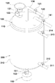
- FIG. 2 is a perspective view showing a state in which the hydrogen generator and the cooling unit shown in FIG. 1 are combined.
- Figure 3 is a cross-sectional view showing the configuration of the hydrogen generator shown in Figure 2;
- Figure 4 is a cross-sectional view showing another embodiment of the hydrogen generator shown in Figure 2;
- Figure 5 is a perspective view showing the configuration of the filtering member shown in Figure 3;
- FIG. 6 is a cross-sectional view showing the configuration of line A-A of FIG. 5;
- FIG. 7 is a block diagram showing a fuel ball input to the hydrogen fuel generator shown in FIG.
- FIG. 8 is a block diagram showing another embodiment of the fuel ball shown in FIG.
- FIG. 9 is a cross-sectional view showing another embodiment of the cooling member shown in FIG. 3.
- FIG. 10 is a cross-sectional view showing the configuration of a filtering unit of the hydrogen fuel generator according to the present invention.
- FIG. 11 is a use state diagram showing a state in which hydrogen gas is produced in the hydrogen generator of the hydrogen fuel generator according to the present invention.
- the hydrogen fuel generator includes: a hydrogen generator 100 for supplying the hydrogen gas generated by the supplied metal fuel ball 160 and the reaction mixture to the filtering unit 300 and separating the sludge; A cooling unit 200 installed on the outer periphery of the hydrogen generating unit 100 so as to maintain a constant temperature when generating hydrogen gas by a chemical reaction of the metal fuel ball 160 and the reaction mixture; Consisting of including, a hydrogen generator 100 and a filtering unit 300 connected to various equipment using hydrogen gas so as to filter out impurities and supply high-purity hydrogen gas. ) And the reaction mixture to produce hydrogen gas, and supply pure hydrogen by removing foreign substances contained in the produced hydrogen gas, so that various devices using the same are operated without trouble.
- FIG. 1 is a schematic configuration diagram of a hydrogen fuel generator according to the present invention
- FIG. 2 is a perspective view showing a state in which the hydrogen generator and the cooling unit shown in FIG. 1 are combined
- FIG. 3 is A cross-sectional view showing the configuration of the generator
- Figure 4 is a cross-sectional view showing another embodiment of the hydrogen generator shown in Figure 2
- Figure 5 is a perspective view showing the configuration of the filtering member shown in Figure 3
- Figure 6 is A cross-sectional view showing the configuration of line AA
- FIG. 7 is a configuration diagram showing a fuel ball input to the hydrogen fuel generator shown in FIG. 3
- FIG. 8 is a configuration diagram showing another embodiment of the fuel ball shown in FIG.
- FIG 7 9 is a cross-sectional view showing another embodiment of the cooling member shown in Figure 3
- Figure 10 is a cross-sectional view showing the configuration of the filtering unit of the hydrogen fuel generator according to the present invention
- Figure 11 is a hydrogen fuel generation according to the present invention It is a usage state diagram showing the state of producing hydrogen gas in the hydrogen generator of the device.
- the hydrogen fuel generator according to the present invention includes a hydrogen generator 100, a cooling part 200, and a filtering part 300.
- the hydrogen generator 100 has a raw material input hole 111 through which raw materials are supplied, a first gas discharge hole 112 through which hydrogen gas is discharged, and a mixture inlet hole 113 through which the reaction mixture is introduced. And, a sediment discharge hole 114 through which sludge is discharged is formed at the bottom, and a hydrogen generating member formed in a cylindrical shape with a space inside so that hydrogen gas can be generated by the chemical reaction of the fuel ball 160 and the reaction mixture ( 110) and a hopper coupled to the raw material injection hole 111 of the hydrogen generating member 110 by a raw material supply pipe 121 installed with a hopper valve 122 so that raw materials can be injected into the upper portion of the hydrogen generating member 110 It has a gas supply valve 131 to supply the hydrogen gas generated from the hydrogen generating member 110 to the filtering unit 300 and is installed in the first gas discharge hole 112 of the hydrogen generating member 110
- the mixture inlet hole 113 of the hydrogen generating member 110 has a gas supply pipe 130 and a mixture supply valve 141 to
- the mixture supply pipe 140 coupled to the fuel ball 160, and the sediment discharge hole 114 of the hydrogen generating member 110 can be attached and detached to isolate the sludge generated when hydrogen gas is generated by the reaction mixture. It consists of a sedimentation box 150 that is coupled together.
- the hydrogen generating member 110 is not limited to a cylindrical shape as shown in the drawing, and may be configured in various shapes such as a square, a hexagonal octagon, or a polygon.
- the inner bottom of the hydrogen generating member 110 is preferably formed to be inclined so that the precipitate generated by the chemical reaction of the fuel ball 160 and the reaction mixture can be easily introduced into the settling body 154.
- the hydrogen generating member 110 is not limited to the configuration shown in FIGS. 2 and 3, and may be implemented differently as shown in FIG. 4.
- a plurality of heat sinks 115 are formed on the outer periphery of the hydrogen generating member 110, and heat generated when hydrogen gas is generated by a chemical reaction is transferred through the heat sink 115. Allows to be easily cooled by cooling water.
- the hopper 120 is not limited to a funnel shape as shown in the drawing, and a ball box (not shown) is configured to store the raw ball 160, and a raw ball 160 is provided at one side of the ball box. ) May be formed in a configuration in which an inlet with a stopper is installed so that it can be injected into the inside. And the ball case is connected to the raw material supply pipe 121 so that the raw material ball 160 can be injected into the hydrogen generating member 110, and the supply of the raw material ball 160 is controlled by the hopper valve 122. .
- the mixture supply pipe 140 is preferably connected to a reaction mixture tank (not shown) so that the reaction mixture can be supplied, and a tank injection port is formed in the reaction mixture tank so that the reaction mixture can be additionally supplemented. .
- the reaction mixture tank with the tank inlet is installed above the hydrogen generating member 110 to be supplied by free fall, and at this time, supply of the reaction mixture And the shut-off is controlled by the mixture supply valve 141 installed in the mixture supply pipe 140.
- the sedimentation bin 150 includes a sediment discharge pipe 151 coupled to a sediment discharge hole 114 formed under the hydrogen generating member 110, and a sediment discharge pipe 151 so that the sediment is discharged while minimizing discharge of the reaction mixture.
- the filter plate 152 is formed in a circular shape, and a plurality of dropping holes 152-1 are formed so that the sediment can be introduced into the settling chamber body 154, and the sedimentation material introduced into the dropping hole 152-1 is
- the diameter of the lower portion is formed wider than the diameter of the upper portion so that it can be dropped while spreading into the interior of the settling chamber body 154.
- the filter plate 152 is not limited to a circular plate shape as shown in the drawing, and is made in a mesh shape so that the sediment can easily flow into the inside of the settling chamber body 154,
- the formed hole is formed to be at least 3mm or more so that the sediment falls easily.
- the sedimentation chamber body 154 is detachably installed in the sediment discharge hole 114 to allow the sludge to flow into the interior to prevent the chemical reaction effect with the reaction mixture from falling due to the sludge, as well as to remove it. .
- the reaction mixture is composed of water and a catalyst to generate hydrogen gas through a chemical reaction with the fuel ball 160.
- the fuel ball 160 is characterized in that it is made of any one of aluminum, magnesium, and zinc made of a metal material.
- the fuel ball 160 is formed of a sphere such as a golf ball, and has a plurality of fine holes to increase the area in contact with the reaction mixture to facilitate production of hydrogen gas.
- the fuel ball is not limited to the shape of a golf ball, and is formed in a thin strip shape and formed in a spherical shape like a golf ball to increase the area in contact with the reaction mixture to facilitate production of hydrogen gas.
- the cooling unit 200 is provided with a cooling member 210 on the outer periphery of the hydrogen generating member 110 to cool heat generated when hydrogen gas is generated by the fuel ball 160 and the reaction mixture.
- the cooling member 210 has a cylindrical shape formed to penetrate from the top to the bottom, and a space for storing coolant is formed while being coupled to the hydrogen generating member 110.
- a first coolant pipe 211 through which coolant flows into the cooling member 210 is formed at the lower side, and a second coolant pipe 213 is installed at the upper side to discharge coolant through which heat exchange has been performed.
- the first cooling water pipe 211 and the second cooling water pipe 213 are respectively provided with a cooling water supply valve 212 and a cooling water discharge valve 214 to control the inflow and discharge of cooling water.
- the cooling water supply valve 212 and the cooling water discharge valve 214 are operated simultaneously or separately when an electrical signal is applied to control the movement of the cooling water.
- the cooling member 210 has a spiral guide member 220 formed therein to facilitate the movement of cooling water in a space formed by being coupled to the hydrogen generating member 110.
- the induction member 220 is made to be in close contact with the outer periphery of the hydrogen generating member 110 while being fixed to the inner side of the cooling member 210 so that heat generated from the hydrogen generating member 110 is transferred to the induction member 220 Cooling is easily accomplished by cooling water.
- a cooling water tank may be configured to circulate the cooling water in the first cooling water pipe 211 and the second cooling water pipe 213 of the cooling member 210, and a pump is installed in the cooling water tank to circulate the cooling water. It is desirable.
- the hydrogen generating unit 100 supplies hydrogen gas to the filtering unit 300 to remove foreign substances contained in the produced hydrogen gas.
- the filtering unit 300 is not limited to being configured in a plurality as shown in the drawing, and the number thereof can be increased or decreased, and the number of the filtering unit 300 is not limited to being installed in series. Makes it easy to remove foreign substances.
- the filtering unit 300 includes a filtering unit body 310 having a space formed therein, and a gas supply pipe 130 installed on the hydrogen generating member 110 is coupled to an upper portion of the filtering unit body 310 Hydrogen gas is supplied, and a water supply pipe 320 is installed on the upper portion of the filtering unit body 310 to supply water for filtering foreign substances contained in the hydrogen gas, and the water supply pipe 320
- a water supply valve 321 is installed in the water supply pipe 320 so as to control the supply of water supplied through the water supply pipe 320, and supply hydrogen gas from which foreign matters have been removed by the water to the other filtration body 310 or
- a gas discharge pipe 330 is installed on the upper portion of the filtering unit body 310 so that it can be supplied to various devices using gas.
- a gas discharge valve 331 is installed in the gas discharge pipe 330 to supply or block hydrogen gas.
- a drain pipe 340 is installed at a lower portion of the filtering unit body 310 so that foreign substances accumulated therein can be discharged together with water, and a drain valve 341 is installed in the drain pipe 340 to It allows foreign substances to be discharged or blocked.
- a sieve may be installed in a transverse direction to prevent foreign matters from moving upward, and these sieves are primarily filtered by water to prevent foreign matters from moving upward. This makes it possible to supply hydrogen gas with high purity by performing secondary filtration.
- the sieve is made of a metal material that does not cause corrosion, or is formed in a plurality of layers using recycled plastic compressed using waste plastic and plastic raw materials to remove foreign substances contained in hydrogen gas.
- a nonwoven fabric made of a fibrous material is installed on one layer, and a nonwoven fabric is not installed on the other layer.
- the water supply valve 321, the gas discharge valve 331, and the drain valve 341 of the filtering unit are not shown in the drawings, but are controlled by a controller equipped with a program for producing hydrogen gas.
- a sensor capable of checking the amount of gas is attached to the gas supply pipe 130 and the gas discharge pipe 330 to which the hydrogen gas is supplied so that the manager can check the supplied amount and the amount discharged.
- the controller is operated to apply an electrical signal to the cooling water supply valve 212 and the cooling water is supplied to the cooling member 210 through the first cooling water pipe 211, and the controller is operated again.
- the reaction mixture that reacts with the fuel ball 160 is supplied to the inside of the hydrogen generating member 110, and then the hopper valve 122 is opened to transfer the fuel ball 160 contained in the hopper 120 to the hydrogen generating member 110. ) To the inside.
- the gas supply valve By opening 131, hydrogen gas is supplied to the filtering unit body 310 of the filtering unit 300 through the gas supply pipe 130.
- the hydrogen gas supplied to the filtering unit body 310 of the filtering unit 300 is filtered by water to remove foreign substances, and a gas so that the hydrogen gas from which the foreign substances have been removed can be supplied to the other filtering unit body 310 again.
- the supply valve 131 is opened and supplied to another adjacent filtering unit body to remove foreign substances contained in the hydrogen gas, thereby supplying high purity hydrogen gas to various devices.
- the sediment generated when hydrogen gas is generated by a chemical reaction is introduced into the sediment chamber body 154 through the sediment discharge pipe 151 through the sediment discharge hole 114 installed in the lower portion of the hydrogen generating member 110.
- the sediment flows through the drop hole 152-1 formed in the filter plate 152 installed in the sediment discharge pipe 151, and the sediment is purged into the inside of the settling chamber body 154 by the drop hole 152-1. While sedimentation occurs, space can be used efficiently.
- the sedimentation chamber 150 is separated from the hydrogen generating member 110 and removed, and then combined with the hydrogen generating member 110 for use.
- the various devices used may be automobiles, for example, and a hydrogen gas battery that uses electricity generated when hydrogen gas of good purity is combined with oxygen by allowing it to flow into the intake manifold of such a vehicle to reduce soot. Can be used as a stack.
- the present invention supplies pure hydrogen by removing foreign substances from hydrogen gas produced by using a fuel ball and a reaction mixture, and thus can be used in various equipment using hydrogen.
Landscapes
- Chemical & Material Sciences (AREA)
- Organic Chemistry (AREA)
- Chemical Kinetics & Catalysis (AREA)
- Health & Medical Sciences (AREA)
- General Health & Medical Sciences (AREA)
- Engineering & Computer Science (AREA)
- Combustion & Propulsion (AREA)
- Inorganic Chemistry (AREA)
- Fuel Cell (AREA)
Abstract
Applications Claiming Priority (2)
| Application Number | Priority Date | Filing Date | Title |
|---|---|---|---|
| KR1020190026418A KR102180516B1 (ko) | 2019-03-07 | 2019-03-07 | 수소 연료 발생장치 |
| KR10-2019-0026418 | 2019-03-07 |
Publications (1)
| Publication Number | Publication Date |
|---|---|
| WO2020180136A1 true WO2020180136A1 (fr) | 2020-09-10 |
Family
ID=72337115
Family Applications (1)
| Application Number | Title | Priority Date | Filing Date |
|---|---|---|---|
| PCT/KR2020/003139 Ceased WO2020180136A1 (fr) | 2019-03-07 | 2020-03-06 | Appareil de génération de combustible à base d'hydrogène |
Country Status (2)
| Country | Link |
|---|---|
| KR (1) | KR102180516B1 (fr) |
| WO (1) | WO2020180136A1 (fr) |
Cited By (2)
| Publication number | Priority date | Publication date | Assignee | Title |
|---|---|---|---|---|
| WO2025243046A1 (fr) | 2024-05-23 | 2025-11-27 | Pheno Therapeutics Limited | Composés |
| WO2025243044A1 (fr) | 2024-05-23 | 2025-11-27 | Pheno Therapeutics Limited | Composés |
Families Citing this family (4)
| Publication number | Priority date | Publication date | Assignee | Title |
|---|---|---|---|---|
| KR102581089B1 (ko) * | 2021-05-24 | 2023-09-22 | 곽건화 | 수소 연료의 정화기능을 갖는 수소 연료 생산시스템 |
| KR102563650B1 (ko) * | 2021-05-24 | 2023-08-08 | 곽건화 | 수소 연료의 연속 생산이 가능한 수소 연료 생산시스템 |
| KR102919313B1 (ko) | 2025-06-02 | 2026-01-29 | (주)오성기업 | 알루미늄을 이용하여 수소를 생산하는 방법 |
| KR102919314B1 (ko) | 2025-06-02 | 2026-01-29 | (주)오성기업 | 알루미늄 고철을 이용하여 수소와 수산화알루미늄을 생산하는 방법 |
Citations (5)
| Publication number | Priority date | Publication date | Assignee | Title |
|---|---|---|---|---|
| JP4782423B2 (ja) * | 2002-09-05 | 2011-09-28 | シエル・インターナシヨネイル・リサーチ・マーチヤツピイ・ベー・ウイ | 高純度水素の製造装置及び方法 |
| KR20110133615A (ko) * | 2009-03-30 | 2011-12-13 | 시그나 케미스트리, 인크. | 규화나트륨 및 나트륨 실리카겔 재료를 사용하는 수소 발생 시스템 및 방법 |
| KR101172941B1 (ko) * | 2009-05-12 | 2012-08-10 | 이규호 | 물을 고온, 고압으로 개질하여 수소를 생산하는 기계장치 |
| KR101835419B1 (ko) * | 2015-12-23 | 2018-03-09 | 임연홍 | 수소수 제조 장치 및 이를 이용한 수소수 제조 방법 |
| KR101939317B1 (ko) * | 2011-06-28 | 2019-01-17 | 인텔리전트 에너지 리미티드 | 수소 가스 발생기 |
Family Cites Families (1)
| Publication number | Priority date | Publication date | Assignee | Title |
|---|---|---|---|---|
| KR100826409B1 (ko) | 2007-01-15 | 2008-05-02 | 삼성전기주식회사 | 수소발생장치 |
-
2019
- 2019-03-07 KR KR1020190026418A patent/KR102180516B1/ko active Active
-
2020
- 2020-03-06 WO PCT/KR2020/003139 patent/WO2020180136A1/fr not_active Ceased
Patent Citations (5)
| Publication number | Priority date | Publication date | Assignee | Title |
|---|---|---|---|---|
| JP4782423B2 (ja) * | 2002-09-05 | 2011-09-28 | シエル・インターナシヨネイル・リサーチ・マーチヤツピイ・ベー・ウイ | 高純度水素の製造装置及び方法 |
| KR20110133615A (ko) * | 2009-03-30 | 2011-12-13 | 시그나 케미스트리, 인크. | 규화나트륨 및 나트륨 실리카겔 재료를 사용하는 수소 발생 시스템 및 방법 |
| KR101172941B1 (ko) * | 2009-05-12 | 2012-08-10 | 이규호 | 물을 고온, 고압으로 개질하여 수소를 생산하는 기계장치 |
| KR101939317B1 (ko) * | 2011-06-28 | 2019-01-17 | 인텔리전트 에너지 리미티드 | 수소 가스 발생기 |
| KR101835419B1 (ko) * | 2015-12-23 | 2018-03-09 | 임연홍 | 수소수 제조 장치 및 이를 이용한 수소수 제조 방법 |
Cited By (2)
| Publication number | Priority date | Publication date | Assignee | Title |
|---|---|---|---|---|
| WO2025243046A1 (fr) | 2024-05-23 | 2025-11-27 | Pheno Therapeutics Limited | Composés |
| WO2025243044A1 (fr) | 2024-05-23 | 2025-11-27 | Pheno Therapeutics Limited | Composés |
Also Published As
| Publication number | Publication date |
|---|---|
| KR102180516B1 (ko) | 2020-11-19 |
| KR20200108180A (ko) | 2020-09-17 |
Similar Documents
| Publication | Publication Date | Title |
|---|---|---|
| KR102180516B1 (ko) | 수소 연료 발생장치 | |
| CA3115360C (fr) | Procede de production d'hydrogene et de production d'energie electrique | |
| US8652693B2 (en) | Reformer, cell stack device, fuel cell module, and fuel cell device | |
| TWI301158B (en) | Hydrogen production system | |
| TW200405610A (en) | Gas generation system | |
| CN214829020U (zh) | 一种天然气制氢系统 | |
| EP1355372B1 (fr) | Dispositif et procédé pour la production d'un gaz dans une pile combustible | |
| KR20120092503A (ko) | 고온 연료 전지 시스템 | |
| JP2000501227A (ja) | 高温燃料電池設備の運転方法及び高温燃料電池設備 | |
| HK1048143A1 (zh) | 电解池中的气液分离方法和装置 | |
| WO2021075802A1 (fr) | Appareil de production d'hydrogène à reformage à la vapeur hautement efficace avec hydrodésulfuration | |
| US12043874B2 (en) | System and method for reducing ore using hydrogen as a reducing agent | |
| US20090110973A1 (en) | Fuel cell system | |
| CN101098019B (zh) | 燃料电池发电系统 | |
| US11211617B2 (en) | Fuel cell generator system | |
| CN106848347A (zh) | 一种供电系统及电力供应的控制方法 | |
| TW200404381A (en) | Hydrogen generating apparatus | |
| CN114744243A (zh) | 用于氢燃料电池的氢气循环供应方法 | |
| WO2011043508A1 (fr) | Dispositif de refroidissement hybride permettant d'évacuer la chaleur de réaction d'un réacteur à colonne à bulles de bouillie de fischer-tropsch | |
| CN213340447U (zh) | 一种固体氧化物燃料电池和固体氧化物电解池的一体化系统 | |
| AU2017295491B2 (en) | Compact methanol reformer for a submarine | |
| CN217164324U (zh) | 非均相法合成碳酸酯的反应系统 | |
| WO2020185028A1 (fr) | Système de traitement de carburant à base de biomasse pour véhicules à pile à combustible à hydrogène | |
| CN117136254A (zh) | 用于处理工艺流体的方法和用于实施该方法的过滤装置 | |
| CN1921199A (zh) | 燃料电池系统 |
Legal Events
| Date | Code | Title | Description |
|---|---|---|---|
| 121 | Ep: the epo has been informed by wipo that ep was designated in this application |
Ref document number: 20766108 Country of ref document: EP Kind code of ref document: A1 |
|
| NENP | Non-entry into the national phase |
Ref country code: DE |
|
| 122 | Ep: pct application non-entry in european phase |
Ref document number: 20766108 Country of ref document: EP Kind code of ref document: A1 |
|
| 32PN | Ep: public notification in the ep bulletin as address of the adressee cannot be established |
Free format text: NOTING OF LOSS OF RIGHTS PURSUANT TO RULE 112(1) EPC (EPO FORM 1205N DATED 28/10/2021) |
|
| 122 | Ep: pct application non-entry in european phase |
Ref document number: 20766108 Country of ref document: EP Kind code of ref document: A1 |