WO2020183211A1 - Procédé de commande de moteur à combustion interne et dispositif de commande de moteur à combustion interne - Google Patents
Procédé de commande de moteur à combustion interne et dispositif de commande de moteur à combustion interne Download PDFInfo
- Publication number
- WO2020183211A1 WO2020183211A1 PCT/IB2019/000252 IB2019000252W WO2020183211A1 WO 2020183211 A1 WO2020183211 A1 WO 2020183211A1 IB 2019000252 W IB2019000252 W IB 2019000252W WO 2020183211 A1 WO2020183211 A1 WO 2020183211A1
- Authority
- WO
- WIPO (PCT)
- Prior art keywords
- internal combustion
- combustion engine
- temperature
- injection valve
- fuel injection
- Prior art date
- Legal status (The legal status is an assumption and is not a legal conclusion. Google has not performed a legal analysis and makes no representation as to the accuracy of the status listed.)
- Ceased
Links
Images

Classifications
-
- F—MECHANICAL ENGINEERING; LIGHTING; HEATING; WEAPONS; BLASTING
- F02—COMBUSTION ENGINES; HOT-GAS OR COMBUSTION-PRODUCT ENGINE PLANTS
- F02D—CONTROLLING COMBUSTION ENGINES
- F02D41/00—Electrical control of supply of combustible mixture or its constituents
- F02D41/02—Circuit arrangements for generating control signals
- F02D41/04—Introducing corrections for particular operating conditions
-
- F—MECHANICAL ENGINEERING; LIGHTING; HEATING; WEAPONS; BLASTING
- F02—COMBUSTION ENGINES; HOT-GAS OR COMBUSTION-PRODUCT ENGINE PLANTS
- F02D—CONTROLLING COMBUSTION ENGINES
- F02D45/00—Electrical control not provided for in groups F02D41/00 - F02D43/00
-
- F—MECHANICAL ENGINEERING; LIGHTING; HEATING; WEAPONS; BLASTING
- F02—COMBUSTION ENGINES; HOT-GAS OR COMBUSTION-PRODUCT ENGINE PLANTS
- F02M—SUPPLYING COMBUSTION ENGINES IN GENERAL WITH COMBUSTIBLE MIXTURES OR CONSTITUENTS THEREOF
- F02M53/00—Fuel-injection apparatus characterised by having heating, cooling or thermally-insulating means
- F02M53/04—Injectors with heating, cooling, or thermally-insulating means
Definitions
- the present invention relates to an internal combustion engine control method and an internal combustion engine control device.
- Patent Document 1 in a so-called port injection type internal combustion engine that injects fuel into an intake port, the throttle valve is opened after the internal combustion engine is stopped, and the temperature of the fuel injection valve becomes a target temperature suitable for fuel atomization.
- a technique for closing the throttle valve when it is determined that the fuel has been reached is disclosed.
- This Patent Document 1 keeps the intake system warm while cooling the fuel injection valve when the internal combustion engine is stopped, and achieves both suppression of deposit generation at the tip of the fuel injection valve and fuel atomization at the time of restart.
- Patent Document 1 focuses on suppressing the generation of deposit, the amount of fuel that wets the nozzle tip of the fuel injection valve when fuel is injected, that is, the fuel adhering to the nozzle tip of the fuel injection valve (Tip-). No consideration is given to wet).
- the internal combustion engine has a fuel injection valve that directly injects fuel into the combustion chamber, and when the temperature of the nozzle tip of the fuel injection valve is a predetermined temperature, the fuel adhesion amount at the nozzle tip becomes the maximum value.
- the temperature at the tip of the nozzle of the fuel injection valve is controlled so as to avoid a temperature range in which the amount of fuel adhered becomes the maximum value.
- the internal combustion engine in an internal combustion engine, fuel is less likely to adhere to the nozzle tip of a fuel injection valve. Therefore, the internal combustion engine can suppress an increase in exhaust fine particles in the exhaust gas due to the fuel adhering to the tip of the nozzle of the fuel injection valve.
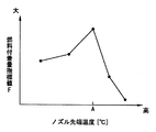
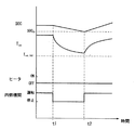
- Explanatory drawing which shows typically the correlation between the fuel adhesion amount index value F and the temperature Tinj of the nozzle tip of a fuel injection valve. Timing chart of the scene where the internal combustion engine restarts due to low battery SOC.
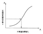
- the characteristic figure which shows the correlation between the target number of exhaust fine particles X and the adhesion amount index value X 1 .
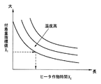
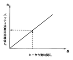
- the characteristic figure which shows the correlation between the battery consumption index value X 4 and the operating time X 2 .
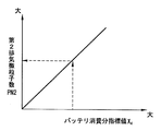
- Characteristic diagram showing the correlation between the second exhaust particulate number PN2 and the battery consumption amount index value X 4.
- the flowchart which shows an example of the control flow of an internal combustion engine.
- FIG. 1 is an explanatory diagram schematically showing an outline of an internal combustion engine 1 to which the present invention is applied.
- FIG. 1 shows only one cylinder for convenience, the internal combustion engine 1 may be a single cylinder or a multi-cylinder engine.
- the internal combustion engine 1 is an in-cylinder direct injection spark-ignition internal combustion engine, which is mounted on a vehicle such as an automobile.
- the internal combustion engine 1 is, for example, one that transmits the rotation of a crankshaft as a driving force to the drive wheels of a vehicle, or one dedicated to power generation mounted on a so-called series hybrid vehicle.
- the internal combustion engine 1 has an intake passage 3 and an exhaust passage 4.
- the intake passage 3 is connected to the combustion chamber 2 via an intake valve 5.
- the exhaust passage 4 is connected to the combustion chamber 2 via an exhaust valve 6.
- the exhaust passage 4 is provided with an exhaust purification catalyst 14 such as a three-way catalyst.
- the exhaust gas purification catalyst 14 is, for example, a so-called underfloor catalyst located under the floor of a vehicle.
- the internal combustion engine 1 includes a cylinder head 7, a cylinder block 8, a piston 10 that reciprocates in the cylinder 9 of the cylinder block 8, and a fuel injection valve 11 that directly injects fuel into the combustion chamber 2 inside the cylinder. And have.
- the piston 10 is connected to a crankshaft (not shown) via a connecting rod 12.
- the fuel injection valve 11 has a plurality of injection ports (not shown) at the tip of the nozzle. The fuel injected from the fuel injection valve 11 is ignited by the spark plug 13 in the combustion chamber 2.
- the temperature Tinj at the tip of the nozzle can be raised by the heater 15.
- the heater 15 is attached to, for example, the nozzle body 11a of the fuel injection valve 11.
- the fuel injection amount of the fuel injection valve 11, the fuel injection timing of the fuel injection valve 11, the ignition timing of the spark plug 13, the pressure of the fuel supplied to the fuel injection valve 11, and the like are controlled by the control unit 21 as a control unit. ..
- the control unit 21 is a well-known digital computer equipped with a CPU, ROM, RAM, and an input / output interface.
- the control unit 21 includes an air flow meter 22 that detects the amount of intake air, a crank angle sensor 23 that detects the crank angle of the crank shaft, an accelerator opening sensor 24 that detects the amount of depression of the accelerator pedal, and a cooling water temperature of the internal combustion engine 1.
- a water temperature sensor 25 for detecting an oil temperature sensor 26 for detecting the lubricating oil temperature of the internal combustion engine 1, a fuel pressure sensor 27 for detecting the fuel pressure Pfeel, and a temperature sensor for detecting the temperature Tinj at the tip of the nozzle of the fuel injection valve 11.
- the detection signals of various sensors such as the nozzle tip temperature sensor 28 and the catalyst temperature sensor 29 that detects the catalyst temperature Tcat of the exhaust purification catalyst 14 are input.
- the control unit 21 calculates the required load (engine load) of the internal combustion engine 1 using the detection value of the accelerator opening sensor 24.
- control unit 21 can detect SOC (State Of Charge), which is the ratio of the remaining charge to the charge capacity of the battery 30 that supplies electric power to the heater 15. That is, the control unit 21 corresponds to the battery SOC detection unit.
- SOC State Of Charge
- the air flow meter 22 has, for example, a built-in temperature sensor and can detect the intake air temperature.
- the crank angle sensor 23 can detect the engine speed of the internal combustion engine 1.
- the fuel pressure sensor 27 detects the pressure of the fuel supplied to the fuel injection valve 11 (fuel pressure Pfuel). In the fuel injection valve 11, the higher the fuel pressure Pfeel, the higher the pressure of the injected fuel.
- the nozzle tip temperature sensor 28 corresponds to the nozzle tip temperature detection unit.
- the temperature Tinj at the tip of the nozzle of the fuel injection valve 11 can be estimated from the electric resistance of the heater 15 by grasping the relationship between the electric resistance of the heater 15 and the temperature in advance. Further, the temperature Tinj at the tip of the nozzle of the fuel injection valve 11 can be estimated by a known method disclosed in Patent Document 1 and the like described above.
- the control unit 21 optimally controls the fuel injection amount, fuel injection timing, ignition timing, etc. of the fuel injection valve 11 based on the detection signals of various sensors.
- the control unit 21 controls ON / OFF of the heater 15 via the switch 31.
- the switch 31 is arranged on the power line 32 that connects the battery 30 and the heater 15.
- the switch 31 is opened and closed based on a control command from the control unit 21.
- the heater 15 When electric power is supplied, the heater 15 generates heat and raises the temperature Tinj at the tip of the nozzle of the fuel injection valve 11.
- the control unit 21 corresponds to a control unit that automatically stops the internal combustion engine 1 when a predetermined automatic stop condition is satisfied, and automatically restarts the internal combustion engine 1 when a predetermined automatic restart condition is satisfied.
- the automatic stop conditions in a vehicle in which the internal combustion engine 1 transmits the rotation of the crankshaft as a driving force to the drive wheels of the vehicle are, for example, a state in which the accelerator pedal is not depressed, and the battery SOC of the battery 30 is predetermined. It is larger than the battery threshold SOC tv , the catalyst temperature T cat of the exhaust gas purification catalyst 14 is higher than the predetermined first catalyst temperature threshold T cat_tv1 and the like.
- the internal combustion engine 1 automatically stops when all of these automatic stop conditions are satisfied.
- the control unit 21 automatically stops the internal combustion engine 1 when all of these automatic stop conditions are satisfied during the operation of the internal combustion engine 1.
- the conditions for automatic restart in a vehicle in which the internal combustion engine 1 transmits the rotation of the crankshaft as a driving force to the drive wheels of the vehicle are, for example, a state in which the accelerator pedal is depressed, and the battery SOC of the battery 30 is predetermined.
- the battery threshold is SOC tv or less
- the catalyst temperature T cat of the exhaust gas purification catalyst 14 is equal to or less than the predetermined first catalyst temperature threshold T cat_tv1 and the like.
- the internal combustion engine 1 restarts when any of these automatic restart conditions is satisfied.
- the control unit 21 restarts the internal combustion engine 1 when any of these automatic restart conditions is satisfied during the automatic stop of the internal combustion engine 1.
- the internal combustion engine 1 that is automatically stopped restarts when the battery SOC of the battery 30 becomes equal to or less than the battery threshold SOC tv as a predetermined value.
- an idle stop, a coast stop, and a sailing stop as automatic stops of the internal combustion engine 1 in a vehicle in which the internal combustion engine 1 transmits the rotation of the crankshaft as a driving force to the drive wheels of the vehicle.
- Idle stop is implemented when the vehicle is temporarily stopped, for example, when the above automatic stop conditions are met. Further, the idle stop is released when any of the above-mentioned automatic restart conditions is satisfied, for example.
- the coast stop is carried out while the vehicle is running, for example, when the above automatic stop conditions are satisfied. Further, the coast stop is canceled when any of the above-mentioned automatic restart conditions is satisfied, for example.
- the coast stop is, for example, automatically stopping the internal combustion engine 1 during deceleration in a state where the brake pedal is depressed at a low vehicle speed.
- Sailing stop is carried out while the vehicle is running, for example, when the above automatic stop conditions are satisfied. Further, the sailing stop is canceled when any of the above-mentioned automatic restart conditions is satisfied, for example.
- the sailing stop is, for example, the automatic stop of the internal combustion engine 1 during coasting when the brake pedal is not depressed at a medium or high vehicle speed.
- the automatic stop condition in the so-called series hybrid vehicle in which the internal combustion engine 1 is mounted for power generation is that, for example, the battery SOC of the battery 30 is larger than a predetermined battery threshold SOC tv during the operation of the internal combustion engine 1. ..
- the automatic restart condition in a so-called series hybrid vehicle in which the internal combustion engine 1 is mounted for power generation is that when the internal combustion engine 1 is stopped while the hybrid vehicle is in operation, for example, the battery SOC of the battery 30 is set to the battery threshold SOC tv. It is as follows.
- the fuel injection valve 11 injects fuel directly into the combustion chamber 2, the nozzle tip is easily affected by the flame during combustion. Therefore, in the internal combustion engine 1, reduction of exhaust fine particles (Particulate Matter) caused by fuel adhering to the nozzle tip of the fuel injection valve 11 becomes an issue.
- the fuel adhering to the nozzle tip of the fuel injection valve 11 wets the outside of the nozzle tip of the fuel injection valve 11 during combustion among the fuel injected from the fuel injection valve 11. It is a fuel (Tip-wet).
- the fuel adhering to the nozzle tip of the fuel injection valve 11 includes the fuel that has exuded from the inside of the nozzle tip of the fuel injection valve 11 to the outside after the fuel injection valve 11 is closed.
- the tip of the valve body (not shown) of the fuel injection valve 11 is seated on the tapered surface (not shown) formed inside the nozzle body 11a, the sack portion is injected with the tip of the valve body (not shown). It is an internal space formed between the valve 11 and the injection port at the tip of the nozzle.
- the fuel injection valve 11 injects fuel when the tip of the valve body (for example, a needle valve) of the fuel injection valve 11 is separated from the tapered surface of the nozzle body 11a.
- the deposit in the present specification is a porous deposit in which a part of the injected fuel or the like is solidified.
- the fuel injection valve 11 has more fuel around the injection port than in the previous cycle.
- the fuel adhesion amount index value F which is an index (Tip-wet-INDEX) of the fuel adhesion amount at the nozzle tip of the fuel injection valve 11 when the fuel is injected, is the fuel injection valve 11
- the temperature Tinj at the tip of the nozzle is the above-mentioned predetermined temperature A (for example, about 90 ° C.)
- the maximum value is reached. That is, the wetting of the fuel injection valve 11 (fuel adhering to the nozzle tip) increases as the temperature Tinj of the nozzle tip of the fuel injection valve 11 rises, but decreases when the temperature exceeds a certain temperature range.
- the temperature of the nozzle tip of the fuel injection valve 11 is tinj so as to avoid the temperature range where the fuel adhesion amount at the nozzle tip of the fuel injection valve 11 becomes the maximum value (peak) by utilizing this characteristic. To control.
- the control unit 21 fuels the fuel injection valve 11.
- the heater 15 is used to raise the temperature Tinj at the tip of the nozzle of the fuel injection valve 11 to be higher than the predetermined temperature A.
- control unit 21 has a temperature Tinj at the tip of the nozzle of the fuel injection valve 11 so as to avoid a temperature range in which the amount of fuel adhering to the tip of the nozzle of the fuel injection valve 11 becomes the maximum value (peak) when the internal combustion engine 1 is started.
- control unit that controls.
- the internal combustion engine 1 makes it difficult for fuel to adhere to the nozzle tip of the fuel injection valve 11. Therefore, the internal combustion engine 1 can suppress an increase in exhaust fine particles in the exhaust gas caused by the fuel adhering to the tip of the nozzle of the fuel injection valve 11.
- the temperature Tinj at the tip of the nozzle of the fuel injection valve 11 does not change so as to straddle the temperature range where the amount of fuel adhering to the tip of the nozzle reaches the maximum value when the internal combustion engine 1 is automatically restarted. Therefore, in the internal combustion engine 1, fuel is less likely to adhere to the nozzle tip of the fuel injection valve 11.
- the internal combustion engine 1 keeps the temperature Tinj at the tip of the nozzle higher than the predetermined temperature A until the internal combustion engine 1 stops. maintain.
- the temperature Tinj at the tip of the nozzle of the fuel injection valve 11 does not change so as to straddle the temperature range where the amount of fuel adhering to the tip of the nozzle becomes the maximum value. Therefore, the internal combustion engine 1 can suppress an increase in exhaust fine particles in the exhaust gas due to the fuel adhering to the tip of the nozzle of the fuel injection valve 11 at all times during combustion.
- the temperature Tinj at the tip of the nozzle of the fuel injection valve 11 becomes high due to the combustion. Therefore, the temperature Tinj at the tip of the nozzle does not operate the heater 15. Can be maintained at a temperature higher than the predetermined temperature A.
- control unit 21 permits the operation of the heater 15 when the internal combustion engine 1 is automatically restarted, but does not permit the operation of the heater 15 when the internal combustion engine 1 is not automatically restarted.
- the catalyst temperature T cat of the exhaust gas purification catalyst 14 is higher than the predetermined second catalyst temperature threshold T cat_tv2 prior to the establishment of the automatic restart condition (starting condition) of the internal combustion engine 1.
- the heater 15 is operated.
- the second catalyst temperature threshold value T cat_tv2 is set as a temperature higher than the first catalyst temperature threshold value T cat_tv1 .
- the second catalyst temperature threshold value T cat_tv2 is the temperature of the exhaust gas purification catalyst 14 that requires the operation of the heater 15.
- control unit 21 does not operate the heater 15 if the catalyst temperature T cat of the exhaust gas purification catalyst 14 is higher than the predetermined second catalyst temperature threshold value T cat_tv2 .
- the internal combustion engine 1 operates the heater 15 at an appropriate timing, so that the battery power consumed by the heater 15 can be minimized.
- FIG. 3 is a timing chart of a scene in which the internal combustion engine 1 restarts due to a decrease in the battery SOC of the battery 30.
- the time t1 in FIG. 3 is the timing at which the internal combustion engine 1 is stopped when the automatic stop condition of the internal combustion engine 1 is satisfied.
- the time t2 in FIG. 3 is the timing at which the internal combustion engine 1 is started when the automatic restart condition of the internal combustion engine 1 is satisfied.
- the battery SOC of the battery 30 becomes equal to or less than the battery threshold SOC tv at the timing of time t2, and the automatic restart condition of the internal combustion engine 1 is satisfied. Further, in the example of FIG. 3, since the catalyst temperature T cat of the exhaust gas purification catalyst 14 is higher than the second catalyst temperature threshold T cat_tv2 at the timing t2 when the automatic restart condition of the internal combustion engine 1 is satisfied, the heater The internal combustion engine 1 is started without operating the 15.
- control unit 21 When the control unit 21 operates the heater 15, the control unit 21 calculates the operating time X 2 of the heater 15 according to the amount of fuel adhered to the tip of the nozzle of the fuel injection valve 11.
- control unit 21 calculates the adhesion amount index value X 1 using the target number of exhaust gas particles X set according to the driving state of the vehicle.
- the adhesion amount index value X 1 is an index value of the fuel adhesion amount adhering to the tip of the nozzle when the number of exhaust particles generated reaches the target number of exhaust particles X.
- the adhesion amount index value X 1 is an index value set so as to increase as the target number of exhaust gas particles X increases, as shown by a broken line in FIG. 4, for example.
- control unit 21 calculates the operating time X 2 of the heater 15 by using the adhesion amount index value X 1 .
- the operating time X 2 of the heater 15 is set to become longer as the adhesion amount index value X 1 becomes smaller and shorter as the temperature Tinj at the nozzle tip of the fuel injection valve 11 becomes higher, as shown by a broken line in FIG. .. That is, in FIG. 5 would operate time X 2 of the heater 15 is calculated using the lower characteristic line higher temperature Tinj of the nozzle tip of the fuel injection valve 11. That is, in FIG. 5, the characteristic line used when calculating the operating time X 2 of the heater 15 from the adhesion amount index value X 1 is properly used according to the temperature Tinj of the nozzle tip of the fuel injection valve 11.
- the operating time X 2 of the heater 15 is set so that when the temperature Tinj of the nozzle tip of the fuel injection valve 11 is higher than the predetermined temperature A, the temperature Tinj of the nozzle tip of the fuel injection valve 11 becomes shorter as the temperature Tinj becomes higher. ..
- the operating time X 2 of the heater 15 is set so that at least the temperature Tinj at the tip of the nozzle of the fuel injection valve 11 is higher than the predetermined temperature A. Further, the operating time X 2 of the heater 15 can be set to “0” when the temperature Tinj at the tip of the nozzle of the fuel injection valve 11 is higher than the predetermined temperature A.
- the internal combustion engine 1 can suppress an increase in exhaust fine particles in the exhaust gas due to the fuel adhering to the tip of the nozzle of the fuel injection valve 11.
- the target number of exhaust particles X may be corrected according to the oil / water temperature of the internal combustion engine 1, the rotational load of the internal combustion engine 1, and the injection pressure of the fuel injection valve 11. More specifically, the target number of exhaust gas particles X may be corrected so that the oil / water temperature expected when the internal combustion engine 1 is restarted or the oil / water temperature when the heater 15 is operated becomes higher. The target number of exhaust fine particles X may be corrected so as to increase as the rotational load expected when the internal combustion engine 1 is restarted increases. The target number of exhaust fine particles X may be corrected so as to increase as the fuel injection pressure set when the internal combustion engine 1 is restarted increases.
- control unit 21 may operate the heater 15 only when the total number of exhaust fine particles discharged during the operation of the internal combustion engine 1 is reduced by operating the heater 15.
- the control unit 21 has a first exhaust particle number PN1 which is the number of exhaust particles expected to be reduced by operating the heater 15 when the internal combustion engine 1 is started when the internal combustion engine 1 is restarted, and a heater 15. This is compared with the number of second exhaust particles PN2, which is the number of exhaust particles that is expected to increase due to the earlier restart timing of the internal combustion engine 1 due to the operation of. Then, the control unit 21 may operate the heater 15 when the number of first exhaust particles PN1 is larger than the number of second exhaust particles PN2.
- the internal combustion engine 1 When the electric power of the battery 30 is consumed by operating the heater 15, the internal combustion engine 1 lowers the battery SOC according to the consumed electric power, so that the timing of starting the next time is earlier by that amount. That is, when the internal combustion engine 1 uses electric power in the heater 15, the restart timing is accelerated.
- the heater 15 when the heater 15 is operated at the time of starting the internal combustion engine 1, the total operating time is longer than when the heater 15 is not operated, and the amount of exhaust fine particles discharged increases by that amount.
- control unit 21 compares the number of first exhaust particles PN1 that can be reduced by operating the heater 15 with the number of second exhaust particles PN2 that increases by operating the heater 15. Then, when the number of first exhaust particles PN1 is larger than the number of second exhaust particles PN2, the control unit 21 operates the heater 15 at the time of starting to raise the temperature Tinj at the tip of the nozzle of the fuel injection valve 11.
- control unit 21 may allow the heater 15 to operate at the time of starting only when the total number of exhaust fine particles discharged during operation is reduced.
- Control unit 21 calculates a first exhaust particulate number PN1 using deposition amount decrease index X 3 is a decrease in the adhesion amount index value X 1.
- control unit 21 calculates the index value X 3 for the amount of decrease in the adhesion amount by using the operating time X 2 of the heater 15.
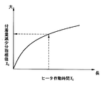
- the adhesion amount reduction index value X 3 is an index value of the fuel adhesion reduction amount at the nozzle tip of the fuel injection valve 11 that is reduced by operating the heater 15.
- the adhesion amount reduction index value X 3 is set to increase as the operating time X 2 of the heater 15 becomes longer.
- control unit 21 calculates a first exhaust particulate number PN1 using deposition amount decrease index X 3.
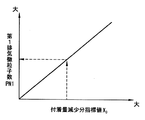
- the first exhaust particulate number PN1 for example, as shown by the broken line in FIG. 7, is set so that the adhesion amount decrease the index value X 3 increases as increases.
- control unit 21 calculates the second exhaust fine particle number PN2 by using the battery consumption index value X 4 that correlates with the battery consumption.
- the control unit 21 calculates the battery consumption index value X 4 by using the operating time X 2 of the heater 15.
- the battery consumption index value X 4 is an index value that correlates with the operating time of the internal combustion engine 1 that has become longer due to the operation of the heater 15.
- the battery consumption index value X 4 is set so as to increase as the operating time X 2 of the heater 15 increases, as shown by a broken line in FIG. 8, for example.
- control unit 21 calculates the second exhaust particulate number PN2 using the battery consumed by the index value X 4.
- the second exhaust fine particle number PN2 is set so as to increase as the battery consumption index value X 4 increases, as shown by a broken line in FIG. 9, for example.
- the total number of exhaust particles discharged during operation can be calculated. It can be reliably suppressed.
- the control unit 21 may set the second catalyst temperature threshold value T cat_tv2 according to the temperature decrease rate of the exhaust gas purification catalyst 14.
- the exhaust gas purification catalyst 14 when the temperature decrease rate of the exhaust gas purification catalyst 14 is large, the exhaust gas purification catalyst 14 has a temperature Tinj at the tip of the nozzle of the fuel injection valve 11 before avoiding a temperature range in which the amount of fuel adhering to the tip of the nozzle becomes the maximum value.
- the catalyst temperature T cat may be less than the first catalyst temperature threshold T cat_tv1 .
- control unit 21 sets a second catalyst temperature threshold value T Cat_tv2 as a difference between the first catalyst temperature threshold value T Cat_tv1 as the temperature decreasing rate is increased and the second catalyst temperature threshold value T Cat_tv2 of the emission control catalyst 14 is increased To do.
- the internal combustion engine 1 can raise the temperature Tinj at the tip of the nozzle of the fuel injection valve 11 by the heater 15 before the catalyst temperature T cat of the exhaust gas purification catalyst 14 becomes less than the first catalyst temperature threshold T cat_tv1. It will be possible. That is, the internal combustion engine 1 can prevent the temperature Tinj at the tip of the nozzle of the fuel injection valve 11 from straddling the temperature range in which the fuel adhesion amount becomes the maximum value at the time of starting.
- the internal combustion engine 1 can suppress the deterioration of the catalyst purification performance due to the temperature drop of the exhaust purification catalyst 14 at the time of starting, and the increase of the exhaust fine particles in the exhaust caused by the fuel adhering to the nozzle tip of the fuel injection valve 11. Can be suppressed. That is, the internal combustion engine 1 can achieve both suppression of deterioration of the catalyst purification performance of the exhaust gas purification catalyst 14 and reduction of the amount of fuel adhering to the tip of the nozzle of the fuel injection valve 11 at the time of starting.
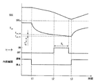
- FIG. 10 is a timing chart of the scene where the internal combustion engine 1 mounted on the vehicle traveling at low speed restarts. That is, FIG. 10 is a timing chart of a scene in which the internal combustion engine 1 restarts when the temperature decrease rate of the exhaust gas purification catalyst 14 is slow.
- the time t1 in FIG. 10 is the timing at which the internal combustion engine 1 is stopped when the automatic stop condition of the internal combustion engine 1 is satisfied.
- the time t2 in FIG. 10 is the timing when the catalyst temperature T cat of the exhaust gas purification catalyst 14 becomes less than the second catalyst temperature threshold value T cat_tv2 and the heater 15 operates.
- the time t3 in FIG. 10 is the timing at which the internal combustion engine 1 is started when the automatic restart condition of the internal combustion engine 1 is satisfied.
- the catalyst temperature T cat of the exhaust gas purification catalyst 14 becomes less than the first catalyst temperature threshold value T cat_tv1 at the timing of time t3, and the automatic restart condition of the internal combustion engine 1 is satisfied.
- the second catalyst temperature threshold value T cat_tv2 is set so that the difference ⁇ T cat_low, which is the difference from the first catalyst temperature threshold value T cat_tv1 , becomes small. ..
- the difference ⁇ T cat_low is a value corresponding to the second catalyst temperature threshold value T cat_tv2 set when the vehicle travels at a low speed.
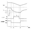
- FIG. 11 is a timing chart showing a scene in which the internal combustion engine 1 mounted on the vehicle traveling at high speed restarts. That is, FIG. 11 is a timing chart of a scene in which the internal combustion engine 1 restarts when the temperature decrease rate of the exhaust gas purification catalyst 14 is high.
- the time t1 in FIG. 11 is the timing at which the internal combustion engine 1 is stopped when the automatic stop condition of the internal combustion engine 1 is satisfied.
- the time t2 in FIG. 11 is the timing at which the catalyst temperature T cat of the exhaust gas purification catalyst 14 becomes less than the second catalyst temperature threshold value T cat_tv2 and the heater 15 operates.
- Time t3 is the timing at which the internal combustion engine 1 is started when the automatic restart condition of the internal combustion engine 1 is satisfied.
- the catalyst temperature T cat of the exhaust gas purification catalyst 14 becomes less than the first catalyst temperature threshold value T cat_tv1 at the timing of time t3, and the automatic restart condition of the internal combustion engine 1 is satisfied.
- the second catalyst temperature threshold value T cat_tv2 is set so that the difference ⁇ T cat_high, which is the difference from the first catalyst temperature threshold value T cat_tv1 , becomes large. ..
- the difference ⁇ T cat_high is a value corresponding to the second catalyst temperature threshold value Tcat_tv2 set when the vehicle travels at high speed.
- the difference ⁇ T cat_high is a larger value than the difference ⁇ T cat_low .
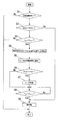
- FIG. 12 is a flowchart showing an example of the control flow of the internal combustion engine 1.
- step S1 it is determined whether or not the internal combustion engine 1 is in a stopped state. If the internal combustion engine 1 is stopped, the process proceeds to step S2. If the internal combustion engine 1 is in operation, this routine ends.
- step S2 it is determined whether or not the battery SOC of the battery 30 is larger than the battery threshold SOC tv . If the battery SOC is larger than the battery threshold SOC tv , the process proceeds to step S3. If the battery SOC is equal to or less than the battery threshold SOC tv , the process proceeds to step S9.
- step S3 it is determined whether or not the catalyst temperature T cat of the exhaust gas purification catalyst 14 is less than the second catalyst temperature threshold T cat_tv2 .
- step S3 if the catalyst temperature T cat is less than the second catalyst temperature threshold T cat_tv2 , the process proceeds to step S4.
- step S3 if the catalyst temperature T cat is equal to or higher than the second catalyst temperature threshold T cat_tv2 , the current routine is terminated.
- step S4 the temperature Tinj at the tip of the nozzle of the fuel injection valve 11 is detected.
- step S5 the operating time X 2 of the heater 15 is calculated.
- step S6 the number of first exhaust particles PN1 and the number of second exhaust particles PN2 are calculated, and the magnitude relationship between the two is compared. In step S6, if the number of first exhaust particles PN1 is larger than the number of second exhaust particles PN2, the process proceeds to step S7. In step S6, if the number of first exhaust particles PN1 is PN2 or less, the process proceeds to step S8.
- step S7 actuating time X 2 operates the heater 15.
- step S8 it is determined whether or not the catalyst temperature T cat of the exhaust gas purification catalyst 14 is less than the first catalyst temperature threshold value T cat_tv1 . In step S8, if the catalyst temperature T cat is less than the first catalyst temperature threshold T cat_tv1 , the process proceeds to step S9.
- step S9 the internal combustion engine 1 is restarted.
- the present invention is not limited to the above-mentioned examples, and various modifications can be made without departing from the spirit of the present invention.
- the temperature Tinj of the nozzle tip of the fuel injection valve 11 is set. It may be controlled so as not to be higher than the predetermined temperature A.
- the temperature Tinj at the tip of the nozzle of the fuel injection valve 11 is maintained at the predetermined temperature A or lower, the temperature range in which the amount of fuel adhering to the tip of the nozzle becomes the maximum value when the internal combustion engine 1 is automatically restarted is set. It does not change to straddle. Therefore, in the internal combustion engine 1, fuel is less likely to adhere to the nozzle tip of the fuel injection valve 11.
- the above-described embodiment relates to a control method for the internal combustion engine 1 and a control device for the internal combustion engine 1.
Landscapes
- Engineering & Computer Science (AREA)
- Chemical & Material Sciences (AREA)
- Combustion & Propulsion (AREA)
- Mechanical Engineering (AREA)
- General Engineering & Computer Science (AREA)
- Combined Controls Of Internal Combustion Engines (AREA)
- Electrical Control Of Air Or Fuel Supplied To Internal-Combustion Engine (AREA)
Abstract
La présente invention concerne un moteur à combustion interne (1) comportant une soupape d'injection de carburant (11) qui injecte directement du carburant dans une chambre de combustion (2). Dans la soupape d'injection de carburant (11), une quantité de fixation de carburant au niveau d'une pointe de buse devient une valeur maximale lorsqu'une température (Tinj) de la pointe de buse est une température prescrite (A). Dans le moteur à combustion interne (1), la température (Tinj) de la pointe de buse de la soupape d'injection de carburant (11) est commandée de façon à éviter une plage de température dans laquelle la quantité de fixation de carburant devient la valeur maximale pendant le démarrage. Par conséquent, le carburant n'est pas facilement fixé à la pointe de buse de la soupape d'injection de carburant (11) dans le moteur à combustion interne (1). Par conséquent, le moteur à combustion interne (1) peut supprimer une augmentation des particules fines d'échappement lors de l'échappement résultant du carburant fixé à la pointe de buse de la soupape d'injection de carburant (11).
Priority Applications (2)
| Application Number | Priority Date | Filing Date | Title |
|---|---|---|---|
| JP2021504586A JP7188554B2 (ja) | 2019-03-13 | 2019-03-13 | 内燃機関の制御方法及び内燃機関の制御装置 |
| PCT/IB2019/000252 WO2020183211A1 (fr) | 2019-03-13 | 2019-03-13 | Procédé de commande de moteur à combustion interne et dispositif de commande de moteur à combustion interne |
Applications Claiming Priority (1)
| Application Number | Priority Date | Filing Date | Title |
|---|---|---|---|
| PCT/IB2019/000252 WO2020183211A1 (fr) | 2019-03-13 | 2019-03-13 | Procédé de commande de moteur à combustion interne et dispositif de commande de moteur à combustion interne |
Publications (1)
| Publication Number | Publication Date |
|---|---|
| WO2020183211A1 true WO2020183211A1 (fr) | 2020-09-17 |
Family
ID=72427789
Family Applications (1)
| Application Number | Title | Priority Date | Filing Date |
|---|---|---|---|
| PCT/IB2019/000252 Ceased WO2020183211A1 (fr) | 2019-03-13 | 2019-03-13 | Procédé de commande de moteur à combustion interne et dispositif de commande de moteur à combustion interne |
Country Status (2)
| Country | Link |
|---|---|
| JP (1) | JP7188554B2 (fr) |
| WO (1) | WO2020183211A1 (fr) |
Citations (4)
| Publication number | Priority date | Publication date | Assignee | Title |
|---|---|---|---|---|
| JP2005002933A (ja) * | 2003-06-13 | 2005-01-06 | Suzuki Motor Corp | 内燃機関の燃料加熱制御装置 |
| JP2005171889A (ja) * | 2003-12-11 | 2005-06-30 | Toyota Motor Corp | 燃料供給装置 |
| JP2009036031A (ja) * | 2007-07-31 | 2009-02-19 | Nissan Motor Co Ltd | 直噴式エンジン及びその制御方法 |
| JP2014222052A (ja) * | 2013-05-14 | 2014-11-27 | トヨタ自動車株式会社 | 内燃機関の燃料噴射装置 |
Family Cites Families (3)
| Publication number | Priority date | Publication date | Assignee | Title |
|---|---|---|---|---|
| JP4305165B2 (ja) | 2003-12-19 | 2009-07-29 | トヨタ自動車株式会社 | 内燃機関 |
| JP2010038000A (ja) | 2008-08-01 | 2010-02-18 | Toyota Motor Corp | 燃料供給装置 |
| BR112018016423B1 (pt) | 2016-02-12 | 2022-02-01 | Nissan Motor Co., Ltd | Método de controle e dispositivo de controle de motor de combustão interna de injeção direta |
-
2019
- 2019-03-13 WO PCT/IB2019/000252 patent/WO2020183211A1/fr not_active Ceased
- 2019-03-13 JP JP2021504586A patent/JP7188554B2/ja active Active
Patent Citations (4)
| Publication number | Priority date | Publication date | Assignee | Title |
|---|---|---|---|---|
| JP2005002933A (ja) * | 2003-06-13 | 2005-01-06 | Suzuki Motor Corp | 内燃機関の燃料加熱制御装置 |
| JP2005171889A (ja) * | 2003-12-11 | 2005-06-30 | Toyota Motor Corp | 燃料供給装置 |
| JP2009036031A (ja) * | 2007-07-31 | 2009-02-19 | Nissan Motor Co Ltd | 直噴式エンジン及びその制御方法 |
| JP2014222052A (ja) * | 2013-05-14 | 2014-11-27 | トヨタ自動車株式会社 | 内燃機関の燃料噴射装置 |
Also Published As
| Publication number | Publication date |
|---|---|
| JPWO2020183211A1 (fr) | 2020-09-17 |
| JP7188554B2 (ja) | 2022-12-13 |
Similar Documents
| Publication | Publication Date | Title |
|---|---|---|
| CN101578447B (zh) | 内燃发动机的控制系统以及该控制系统的控制方法 | |
| US7377248B2 (en) | Engine starting control system of internal combustion engine | |
| US9441569B2 (en) | Engine system and a method of operating a direct injection engine | |
| KR101554468B1 (ko) | 정지/시동 동작에서의 내연 기관 제어 방법 및 장치 | |
| WO2010041308A1 (fr) | Dispositif de régulation d’injection de carburant pour moteur à combustion interne | |
| WO2016084188A1 (fr) | Dispositif et procédé de commande de moteur à combustion interne | |
| CN104033228B (zh) | 冷却发动机活塞的系统和方法 | |
| CN105189996B (zh) | 内燃机的电气控制单元及其方法 | |
| JP4930637B2 (ja) | 内燃機関の燃料噴射制御装置 | |
| JP2008232007A (ja) | 内燃機関の始動制御装置 | |
| JP2009062863A (ja) | 内燃機関の制御装置 | |
| JP2008267293A (ja) | 内燃機関の制御システム | |
| US20180340478A1 (en) | Cooling apparatus of internal combustion engine | |
| JP5829838B2 (ja) | エンジンブレーキ制御装置 | |
| JP5249978B2 (ja) | 車両用内燃機関の燃料噴射制御装置 | |
| JP7188554B2 (ja) | 内燃機関の制御方法及び内燃機関の制御装置 | |
| JP2006144725A (ja) | ハイブリッド車両の燃料噴射制御装置 | |
| JP2010071125A (ja) | 直接噴射式内燃機関の燃料噴射制御装置 | |
| JP7183444B2 (ja) | 車両制御システム及び内燃機関制御装置 | |
| JP7160177B2 (ja) | 内燃機関の制御方法及び内燃機関の制御装置 | |
| JP4894815B2 (ja) | 車両用内燃機関の燃料圧力制御装置 | |
| JP2006266116A (ja) | 内燃機関の燃料噴射制御装置 | |
| JP6070980B2 (ja) | 内燃機関の制御装置 | |
| JP7160176B2 (ja) | 燃料噴射弁のノズル先端の燃料付着量の推定方法、燃料噴射弁のノズル先端の燃料付着量を用いた内燃機関の制御方法及び燃料噴射弁のノズル先端の燃料付着量を用いた内燃機関の制御装置 | |
| JP2009257211A (ja) | 内燃機関の制御システム |
Legal Events
| Date | Code | Title | Description |
|---|---|---|---|
| 121 | Ep: the epo has been informed by wipo that ep was designated in this application |
Ref document number: 19918504 Country of ref document: EP Kind code of ref document: A1 |
|
| ENP | Entry into the national phase |
Ref document number: 2021504586 Country of ref document: JP Kind code of ref document: A |
|
| NENP | Non-entry into the national phase |
Ref country code: DE |
|
| 122 | Ep: pct application non-entry in european phase |
Ref document number: 19918504 Country of ref document: EP Kind code of ref document: A1 |