WO2020183512A1 - Dispositif d'affichage de fontionnement d'ascenseur - Google Patents
Dispositif d'affichage de fontionnement d'ascenseur Download PDFInfo
- Publication number
- WO2020183512A1 WO2020183512A1 PCT/JP2019/009254 JP2019009254W WO2020183512A1 WO 2020183512 A1 WO2020183512 A1 WO 2020183512A1 JP 2019009254 W JP2019009254 W JP 2019009254W WO 2020183512 A1 WO2020183512 A1 WO 2020183512A1
- Authority
- WO
- WIPO (PCT)
- Prior art keywords
- plate
- display device
- gap adjusting
- operation display
- face plate
- Prior art date
- Legal status (The legal status is an assumption and is not a legal conclusion. Google has not performed a legal analysis and makes no representation as to the accuracy of the status listed.)
- Ceased
Links
Images



Classifications
-
- B—PERFORMING OPERATIONS; TRANSPORTING
- B66—HOISTING; LIFTING; HAULING
- B66B—ELEVATORS; ESCALATORS OR MOVING WALKWAYS
- B66B1/00—Control systems of elevators in general
- B66B1/34—Details, e.g. call counting devices, data transmission from car to control system, devices giving information to the control system
- B66B1/46—Adaptations of switches or switchgear
-
- B—PERFORMING OPERATIONS; TRANSPORTING
- B66—HOISTING; LIFTING; HAULING
- B66B—ELEVATORS; ESCALATORS OR MOVING WALKWAYS
- B66B3/00—Applications of devices for indicating or signalling operating conditions of elevators
- B66B3/02—Position or depth indicators
Definitions
- the present invention relates to an elevator operation display device used for a landing or the like.
- the elevator platform is equipped with an operation display device that registers the destination floor and displays the car position.
- the equipment used in the operation display device is a precision equipment, and it is necessary to prevent the ingress of dust and the like.
- Prior literature with this measure is disclosed. (For example, Patent Document 1).
- a sealing member is arranged between the peripheral surface on the back side of the face plate and the peripheral edge of the opening on the surface of the mounting panel. This makes it possible to handle special environments such as outdoors.
- the seal member of Patent Document 1 is a rubber packing, and it is necessary to prepare several types according to the size of the operation display device. Therefore, using rubber packing is costly.
- the present invention has been made to solve the above problems, and an object of the present invention is to supply an operation display device capable of preventing the ingress of dust with a simple configuration.
- the elevator operation display device is an elevator operation display device having a display unit on the face plate, and is provided on a display unit inserted into an opening provided in the face plate and a side portion of the display unit. It is inserted into one end between a display plate having a flange portion whose outer periphery is larger than the opening, a presser plate for fixing the display plate to the back surface of the face plate, and the presser plate and the back surface of the face plate. It is provided with a spacer and a gap adjusting plate that is inserted into the other end between the holding plate and the back surface of the face plate so that the gap can be adjusted.
- Embodiment 1 1 to 3 are views for explaining the first embodiment of the present invention.
- the elevator landing 1 shown in FIG. 1 is provided with an entrance / exit 2 having a double door 3.
- An operation display device 4 that can confirm destination settings, driving conditions, and the like is installed on the building wall 5 provided with the doorway 2.
- the operation display device 4 is a type in which a part of the main body is embedded in the building wall 5.
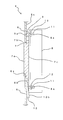
- FIG. 2 shows a cross-sectional view of the operation display device 4.
- FIG. 2 shows the area around the display board 7 in particular in the II-II cross section of FIG.
- a face plate 6 is attached to the front surface of the operation display device 4.
- the display portion 7a of the display plate 7 is inserted into the opening portion 6a of the face plate 6.
- the display plate 7 is pressed and fixed to the face plate 6 by the pressing plate 8.
- the face plate 6 is provided with studs 11 on the upper and lower parts of the back surface. Further, an opening 6a for inserting the display portion 7a of the display plate 7 is provided. A spacer 9 is inserted into the upper stud 11 of the back surface 6c of the face plate 6 through the hole 9a, and a gap adjusting plate 10 is inserted into the lower stud 11 through the elongated hole 10a.
- the display plate 7 is provided with a flange portion 7b for fixing to the face plate 6 on the side portion of the display portion 7a.
- the flange portion 7b comes into contact with the back surface 6c of the face plate 6.
- the material of the display board 7 is a translucent resin.
- a display unit (not shown) for displaying characters, numbers, etc. is provided behind the display board 7 via the display board 7.
- the pressing plate 8 has a pressing surface 8b for pressing and fixing the display plate 7 against the face plate 6.
- the pressing plate 8 is fixed to the face plate 6 by inserting the stud 11 into the holes 8a provided in the upper and lower portions and fastening the stud 11 with the nut 12.
- the spacer 9 has a hole 9a for passing the stud 11, and has substantially the same thickness as the flange portion 7b of the display plate 7.
- the gap adjusting plate 10 has a wedge-shaped cross section, and the joint surface 10b in contact with the pressing surface 8b of the pressing plate 8 is inclined.
- the gap adjusting plate 10 has an elongated hole 10a for passing the stud 11 at one end where the plate thickness is reduced due to the inclination of the joint surface 10b.
- the joint surface 10b is inclined from one end side with the elongated hole 10a toward the other end side, and the plate thickness on the other end side is larger than that on the one end side.
- the elongated hole 10a is formed from one end side to the other end side. The gap adjusting plate 10 can be moved up and down by the length of the elongated hole 10a.
- the amount of gap between the holding plate 8 and the face plate 6 can be adjusted by moving the gap adjusting plate 10 in the display plate 7 direction (up and down) when the holding plate 8 is fixed by fastening the nut 12.
- the gap adjusting plate 10 is moved in the direction of the display plate 7, the thickness of the portion in contact with the pressing plate 8 increases, so that the gap amount between the pressing plate 8 and the face plate 6 increases.
- the gap adjusting plate 10 is moved away from the display plate 7, the thickness of the portion in contact with the pressing plate 8 becomes smaller, so that the amount of gap between the pressing plate 8 and the face plate 6 becomes smaller.
- the amount of pressing of the flange portion 7b of the display plate 7 against the back surface 6c of the face plate 6 is adjusted.
- the amount of pressing of the flange portion 7b of the display plate 7 against the back surface 6c of the face plate 6 also increases.
- the amount of pressure of the flange portion 7b of the display plate 7 against the back surface 6c of the face plate 6 increases, the amount of the gap also decreases, and the seal is eventually sealed.
- the following effects can be obtained.
- the display unit 7a inserted into the opening portion 6a provided on the face plate 6 and the outer periphery provided on the side portion of the display unit 7a are larger than the opening portion 6a.
- the gap adjusting plate 10 Since the gap adjusting plate 10 is provided at the other end between the holding plate 8 and the back surface 6c of the face plate 6 so that the gap can be adjusted, the gap adjusting plate 10 can be moved to move the display plate 7. The gap between the flange portion 7b and the back surface 6c of the face plate 6 can be adjusted to seal the face plate 6.
- the gap adjusting plate 10 is used at the fixing location, so that the operation display device is sealed with a simple configuration to allow dust to enter. Can be prevented.
- gap adjusting plate 10 if one type of gap adjusting plate 10 is prepared, it can be used for operation display devices of almost all sizes, so that the cost can be reduced. Since the cross section of the gap adjusting plate 10 is formed in a substantially wedge shape, the amount of gap between the face plate 6 and the holding plate 8 can be continuously changed.
- FIG. 4 shows a gap adjusting plate according to the second embodiment. It is the same as the first embodiment except for the gap adjusting plate.
- the gap adjusting plate 13 shown in FIG. 4 is provided with a hole 14a through which the stud 11 is passed on one end side of a substantially quadrangular sheet metal 14, and a thin plate 15 is attached to the other end side.
- the thin plate 15 is attached only to one side (surface) of the sheet metal 14.
- the gap adjusting plate 13 is attached so that the stud 11 is passed through the hole 14a and the surface to which the thin plate 15 is attached is in contact with the face plate 6. Further, the gap adjusting plate 13 is attached with one end side provided with the hole 14a facing the display plate 7. Then, the pressing plate 8 sandwiches the surface of the thin plate 15 on which the thin plate 15 is not attached.
- the hole 14a may be an elongated hole formed from one end side to the other end side of the gap adjusting plate 13.
- the gap adjusting plate 13 has the thin plate 15 attached to the end of one surface of the sheet metal 14, it is possible to obtain the same effect as the gap adjusting plate 10 having a wedge-shaped cross section with a simple structure.
- FIG. 5 shows a gap adjusting plate according to the third embodiment. It is the same as the first embodiment except for the gap adjusting plate.
- the gap adjusting plate 16 shown in FIG. 5 is provided with a hole 14a through which the stud 11 is passed on one end side of a substantially quadrangular sheet metal 14, and has a coating film 17 on the other end side.
- the coating film 17 is continuously applied to both surfaces including the other end of the sheet metal 14.
- the gap adjusting plate 16 is attached by passing the stud 11 through the hole 14a. Further, the gap adjusting plate 16 is attached with the one end side having the hole 14a facing the display plate 7. Then, the portion of the gap adjusting plate 16 to which the coating film 17 is applied is sandwiched by the pressing plate 8.
- the hole 14a may be an elongated hole formed from one end side to the other end side of the gap adjusting plate 16.
- the gap adjusting plate 16 is coated with the coating film 17 on a part of the sheet metal 14, it is possible to obtain the same effect as the wedge-shaped gap adjusting plate 10 with a simple structure of simply applying the coating film 17.
Landscapes
- Engineering & Computer Science (AREA)
- Automation & Control Theory (AREA)
- Computer Networks & Wireless Communication (AREA)
- Indicating And Signalling Devices For Elevators (AREA)
Abstract
L'intérieur d'un dispositif d'affichage de fonctionnement comporte un équipement de précision, et l'infiltration de poussière ou analogue doit être évitée. Ce dispositif d'affichage de fonctionnement (4) peut empêcher l'infiltration de poussière ou analogue par une configuration comprenant: une plaque d'affichage (7) qui possède une unité d'affichage (7a) qui s'adapte dans une ouverture (6a) ménagée dans une plaque avant (6); une plaque de maintien (8) qui fixe la plaque d'affichage (7) à la face arrière de la plaque avant (6); un élément d'espacement (9) qui est inséré dans un espace à une extrémité entre la plaque de maintien (8) et la face arrière de la plaque avant (6); et une plaque de réglage d'espace (10) qui est insérée dans un espace à l'autre extrémité entre la plaque de maintien (8) et la face arrière de la plaque avant (6) et présente une section transversale ayant une forme de coin substantielle.
Priority Applications (1)
| Application Number | Priority Date | Filing Date | Title |
|---|---|---|---|
| PCT/JP2019/009254 WO2020183512A1 (fr) | 2019-03-08 | 2019-03-08 | Dispositif d'affichage de fontionnement d'ascenseur |
Applications Claiming Priority (1)
| Application Number | Priority Date | Filing Date | Title |
|---|---|---|---|
| PCT/JP2019/009254 WO2020183512A1 (fr) | 2019-03-08 | 2019-03-08 | Dispositif d'affichage de fontionnement d'ascenseur |
Publications (1)
| Publication Number | Publication Date |
|---|---|
| WO2020183512A1 true WO2020183512A1 (fr) | 2020-09-17 |
Family
ID=72426011
Family Applications (1)
| Application Number | Title | Priority Date | Filing Date |
|---|---|---|---|
| PCT/JP2019/009254 Ceased WO2020183512A1 (fr) | 2019-03-08 | 2019-03-08 | Dispositif d'affichage de fontionnement d'ascenseur |
Country Status (1)
| Country | Link |
|---|---|
| WO (1) | WO2020183512A1 (fr) |
Cited By (1)
| Publication number | Priority date | Publication date | Assignee | Title |
|---|---|---|---|---|
| JP7271737B1 (ja) | 2022-01-17 | 2023-05-11 | 東芝エレベータ株式会社 | ボタン装置、操作盤、および乗りかご |
Citations (6)
| Publication number | Priority date | Publication date | Assignee | Title |
|---|---|---|---|---|
| JPS62115924U (fr) * | 1986-01-16 | 1987-07-23 | ||
| JPH0310403Y2 (fr) * | 1984-12-07 | 1991-03-14 | ||
| JPH0698424A (ja) * | 1991-06-24 | 1994-04-08 | Mitsubishi Electric Corp | 開閉装置の化粧パネル取付け調整装置 |
| JPH0617816Y2 (ja) * | 1987-08-12 | 1994-05-11 | フジテック株式会社 | エレベ−タ用機器 |
| JPH07223782A (ja) * | 1994-02-03 | 1995-08-22 | Otis Elevator Co | エレベーターのかごの出入口 |
| JP2002226159A (ja) * | 2001-01-29 | 2002-08-14 | Toshiba Elevator Co Ltd | エレベータのかご室 |
-
2019
- 2019-03-08 WO PCT/JP2019/009254 patent/WO2020183512A1/fr not_active Ceased
Patent Citations (6)
| Publication number | Priority date | Publication date | Assignee | Title |
|---|---|---|---|---|
| JPH0310403Y2 (fr) * | 1984-12-07 | 1991-03-14 | ||
| JPS62115924U (fr) * | 1986-01-16 | 1987-07-23 | ||
| JPH0617816Y2 (ja) * | 1987-08-12 | 1994-05-11 | フジテック株式会社 | エレベ−タ用機器 |
| JPH0698424A (ja) * | 1991-06-24 | 1994-04-08 | Mitsubishi Electric Corp | 開閉装置の化粧パネル取付け調整装置 |
| JPH07223782A (ja) * | 1994-02-03 | 1995-08-22 | Otis Elevator Co | エレベーターのかごの出入口 |
| JP2002226159A (ja) * | 2001-01-29 | 2002-08-14 | Toshiba Elevator Co Ltd | エレベータのかご室 |
Cited By (2)
| Publication number | Priority date | Publication date | Assignee | Title |
|---|---|---|---|---|
| JP7271737B1 (ja) | 2022-01-17 | 2023-05-11 | 東芝エレベータ株式会社 | ボタン装置、操作盤、および乗りかご |
| JP2023104362A (ja) * | 2022-01-17 | 2023-07-28 | 東芝エレベータ株式会社 | ボタン装置、操作盤、および乗りかご |
Similar Documents
| Publication | Publication Date | Title |
|---|---|---|
| US9850700B2 (en) | Waterproofing member and exterior wall structure | |
| WO2020183512A1 (fr) | Dispositif d'affichage de fontionnement d'ascenseur | |
| US4803817A (en) | Glazing assembly and method for glazing a building | |
| JP3341717B2 (ja) | 密閉筐体構造 | |
| US20230383527A1 (en) | Self-adhered system for sealing between adjacent building structural elements | |
| WO2016139750A1 (fr) | Panneau d'actionnement pour ascenseur | |
| JP2005132517A (ja) | エレベータドアの改修方法 | |
| KR960000749A (ko) | 엘리베이터용 허니콤패널 및 그의 체결구조와 그 체결방법 | |
| US5364673A (en) | Transparent plate-shaped component having a stepped edge totally surrounded by a seal | |
| US20180350842A1 (en) | Array substrate, display panel and manufacturing method thereof | |
| JP3934764B2 (ja) | 外壁材 | |
| JP2022015045A (ja) | 板金接着品および板金接着品の接着方法 | |
| CA1284713C (fr) | Ensemble et methode de vitrage pour le batiment | |
| JP2000034791A (ja) | 柱耐火被覆構造 | |
| JP2000211853A (ja) | エレベ―タ―の乗りかご | |
| JP3103925B2 (ja) | 耐火被覆材の取付装置 | |
| KR100525195B1 (ko) | 건축 외장재 고정장치 | |
| JP3033527B2 (ja) | コンクリート躯体表面防塵方法 | |
| JPH0517072U (ja) | ドア枠 | |
| JP2005026083A (ja) | 有機エレクトロルミネセンス表示パネル | |
| JPH078657Y2 (ja) | 建築物外壁における目地部密封構造 | |
| JP3166342B2 (ja) | 外壁パネルの接合構造 | |
| JPH0542884Y2 (fr) | ||
| JP3249319B2 (ja) | エレベータの意匠部品 | |
| JPH0625407U (ja) | 外壁プレハブパネルの目地構造 |
Legal Events
| Date | Code | Title | Description |
|---|---|---|---|
| 121 | Ep: the epo has been informed by wipo that ep was designated in this application |
Ref document number: 19918967 Country of ref document: EP Kind code of ref document: A1 |
|
| NENP | Non-entry into the national phase |
Ref country code: DE |
|
| 122 | Ep: pct application non-entry in european phase |
Ref document number: 19918967 Country of ref document: EP Kind code of ref document: A1 |
|
| NENP | Non-entry into the national phase |
Ref country code: JP |