WO2020183594A1 - Aéronef à décollage vertical - Google Patents
Aéronef à décollage vertical Download PDFInfo
- Publication number
- WO2020183594A1 WO2020183594A1 PCT/JP2019/009836 JP2019009836W WO2020183594A1 WO 2020183594 A1 WO2020183594 A1 WO 2020183594A1 JP 2019009836 W JP2019009836 W JP 2019009836W WO 2020183594 A1 WO2020183594 A1 WO 2020183594A1
- Authority
- WO
- WIPO (PCT)
- Prior art keywords
- propellers
- main wings
- tail
- flight
- aircraft
- Prior art date
- Legal status (The legal status is an assumption and is not a legal conclusion. Google has not performed a legal analysis and makes no representation as to the accuracy of the status listed.)
- Ceased
Links
Images






Classifications
-
- B—PERFORMING OPERATIONS; TRANSPORTING
- B64—AIRCRAFT; AVIATION; COSMONAUTICS
- B64C—AEROPLANES; HELICOPTERS
- B64C29/00—Aircraft capable of landing or taking-off vertically, e.g. vertical take-off and landing [VTOL] aircraft
Definitions
- the present invention relates to a tailsitter type air vehicle.
- Non-Patent Document 1 a tailsitter type air vehicle capable of vertical takeoff and landing is known (see, for example, Non-Patent Document 1).
- the tailsitter type air vehicle disclosed in Non-Patent Document 1 includes a fuselage, left and right (pair) main wings, and left and right (pair) propellers provided on each main wing (in the present specification, the pair). (Including what is commonly referred to as a rotor), when the aircraft transitions from vertical or hovering after takeoff to horizontal flight, and when transitioning from horizontal flight to pre-landing vertical or hovering. , The aircraft makes a posture transition of about 90 degrees.
- Such a tailsitter type air vehicle obtains lift or propulsion by two rotating propellers.
- Such a tailsitter type aircraft can hover and take off and land vertically like a helicopter when the propeller is facing upward, such as the so-called Osprey disclosed in Non-Patent Document 2, and the propeller is tilted forward.
- Osprey disclosed in Non-Patent Document 2
- it is excellent in that it does not require space for takeoff and landing such as a runway, like a fixed-wing aircraft capable of long-distance flight at high speed, and also with an aircraft such as the above-mentioned Osprey.
- a drive mechanism for tilting the propeller is not required, it is extremely excellent in terms of weight reduction and energy reduction.
- the present invention has been made in view of the above background, and provides a tail-sitter type aircraft capable of roll control, pitch control, and yaw control, which is more accurate and responsive than the conventional one. With the goal.
- the tail-sitter type air vehicle of the present invention is provided with two main wings, two each of the four main wings connected to the body in an X-shape in front view, and lift or propulsion.
- Eight propellers for obtaining force and eight electric motors having a one-to-one correspondence with the eight propellers and controlling the rotation speed of each of the eight propellers are provided, and the eight propellers are said to have the above-mentioned eight propellers. It is characterized in that it is composed of four inner propellers provided inside the leading edges of each of the four main wings and four outer propellers provided outside the leading edges of each of the four main wings. ..
- the tail-sitter type air vehicle of the present invention four main wings connected to the fuselage and two for each of the four main wings are provided in an X-shape in a front view to obtain lift or propulsion. Equipped with eight propellers and eight electric motors that have a one-to-one correspondence with each of the eight propellers and control the rotational speed of each of the eight propellers, the eight propellers are on the leading edge of each of the four main wings. Since it is composed of four inner propellers provided on the inner side and four outer propellers provided on the outer side of the leading edge of each of the four main wings, it is more accurate and more responsive than before. Roll control, pitch control and yaw control are possible.
- the rotation speeds of the two inner propellers and the two outer propellers provided on the two main wings on the upper right side and the lower left side in front view during level flight and the front view during level flight are created by creating a rotation speed difference between the rotation speeds of the two inner propellers and the two outer propellers provided on the two main wings on the upper left and lower right sides.
- the above-mentioned roll control is performed during vertical flight and horizontal flight. And possible during hovering.
- the rotation speeds of the two inner propellers and the two outer propellers provided on the two main wings on the upper front view during level flight and the two main wings on the lower front view during level flight are created by creating a rotation speed difference between the rotation speeds of the two inner propellers and the two outer propellers provided in the above-mentioned pitch control.
- the rotation speeds of the two inner propellers and the two outer propellers provided on the two main wings on the right side of the front view during level flight and the two main wings on the left side of the front view during level flight are created.
- the two inner propellers provided on each of the two main wings that are located on the upper side during level flight have opposite rotation directions. It is also possible that the two inner propellers provided on each of the two main wings, which are located on the lower side during level flight, have opposite rotation directions.
- the two outer propellers provided on each of the two main wings that are located on the upper side during level flight have opposite rotation directions.
- the two outer propellers provided on each of the two main wings that will be located on the lower side during level flight can be assumed to have opposite rotation directions.
- the tail-sitter type flying object of the present invention may further include four moving blades provided at the trailing edges of each of the four main wings.
- the fuselage has an in-flight space inside, and a seat that tilts according to the attitude of the aircraft is provided in the in-flight space, and the seat is seated on the seat. It can be tilted so that the passenger is facing horizontally.
- the seat can be further extended back and forth during level flight.
- the four main wings are separated from each other and connected to the airframe, and the airframe has a lower window portion located on the lower side of the airframe during horizontal flight and the airframe. It is possible to have a right window portion located on the right side during horizontal flight, a left window portion located on the left side during horizontal flight of the airframe, and a pillar portion connecting adjacent main wings.
- FIG. 5 is a perspective view seen from the front showing an example of the tail sitter type flying object 1 according to the first embodiment during level flight.
- FIG. 5 is a perspective view seen from the rear showing an example of the tail sitter type flying object 1 according to the first embodiment during level flight. It is a figure for demonstrating an example from takeoff to landing of the tail sitter type flying object 1 which concerns on Embodiment 1.
- FIG. 5 is a perspective view seen from the front showing an example of the tail sitter type flying object 1 according to the first embodiment during level flight.
- FIG. 5 is a perspective view seen from the rear showing an example of the tail sitter type flying object 1 according to the first embodiment during level flight.
- FIG. 2 It is a perspective view of the tail sitter type flying object 100 which concerns on Embodiment 2.
- FIG. It is a block diagram for demonstrating the structure of the tail sitter type flying object 100 which concerns on Embodiment 2.
- FIG. It is a figure for demonstrating an example from takeoff to level flight of the tail sitter type flying object 100 which concerns on Embodiment 2.
- FIG. It is a figure for demonstrating an example from level flight to landing of the tail sitter type flying object 100 which concerns on Embodiment 2.
- FIG. It is a block diagram for demonstrating the structure of the modification of the tail sitter type flying object 100 which concerns on Embodiment 2.
- tail-sitter type flying object of the present invention will be described in detail based on the embodiment shown in the figure. It should be noted that all the structures shown in the drawings are schematic, and the display of dimensions, angles, etc. is not always realistic. Further, substantially the same components are designated by the same reference numerals across the embodiments, and the description thereof will be omitted again.
- the configuration diagram 1 of the tail sitter type air vehicle is a perspective view of the tail sitter type air vehicle 1 according to the first embodiment.
- the tailsitter type aircraft 1 according to the first embodiment is a so-called unmanned vertical take-off and landing aircraft.
- the tailsitter type air vehicle 1 has a fuselage 20, four main wings 30a, 30b, 30c, 30d, four moving blades 40a, 40b, 40c, 40d, and four blades. It includes inner propellers 50a, 50b, 50c, 50d and four outer propellers 60a, 60b, 60c, 60d.
- the main wing 30a corresponds to the main wing on the upper right side of the front view during level flight.
- the main wing 30b corresponds to the main wing on the upper left side of the front view during level flight.
- the main wing 30c corresponds to the main wing on the lower left side of the front view during level flight.
- the main wing 30d corresponds to the main wing on the lower right side of the front view during level flight.
- the fuselage 20 is an egg shape in which the traveling direction of the fuselage is longitudinal.
- the body 20 shown in FIG. 1 has an egg shape in which the traveling direction of the machine body is longitudinal, but the shape of the body 20 is not limited to the egg shape.
- the fuselage 20 may have a spherical shape or a sharp nose.
- the fuselage 20 is the base of the four main wings 30a, 30b, 30c, 30d.
- the body 20 houses a battery 21 and the like, which will be described later.
- the four main wings 30a, 30b, 30c, and 30d are connected to the fuselage 20 in an X-shape when viewed from the front.
- the front view means "when the aircraft is viewed from the front side” when the traveling direction side during level flight is the front side and the opposite direction side of the traveling direction is the back side.
- the four main wings are connected to the fuselage in an X-shape in the front view
- the main wing 30a in the upper right of the front view and the main wing 30c in the lower left of the front view are located on a straight line, and the main wing in the upper left of the front view.
- the "angle” is preferably smaller than 90 degrees, and even more preferably in the range of, for example, 20 to 70 degrees. When these angles are 20 degrees or more, it becomes easy to suppress the interference between the inner propeller provided on the upper main wing and the inner propeller provided on the lower main wing, and these angles are 70 degrees or less. In some cases, it is possible to increase the lift of the main wing generated during level flight.
- the four main wings 30a, 30b, 30c, 30d have a tailless aerodynamic surface.
- the tailsitter type aircraft 1 according to the first embodiment does not include not only the horizontal stabilizer but also the vertical stabilizer.
- the tailsitter type aircraft 1 according to the first embodiment does not include an elevator or a ladder.
- the four rotor blades 40a, 40b, 40c, and 40d are arranged at the trailing edges of the main blades 30a, 30b, 30c, and 30d, respectively.
- the four blades 40a, 40b, 40c, and 40d are so-called elevons.
- the four inner propellers 50a, 50b, 50c, and 50d are arranged inside the leading edges of the four main wings 30a, 30b, 30c, and 30d, respectively.
- Each inner propeller 50a, 50b, 50c, 50d is composed of a fixed pitch type propeller.
- the four outer propellers 60a, 60b, 60c, and 60d are arranged outside the leading edges of the four main wings 30a, 30b, 30c, and 30d, respectively.
- Each outer propeller 60a, 60b, 60c, 60d is composed of a fixed pitch type propeller.
- two propellers are arranged on each of the four main wings 30a, 30b, 30c, and 30d, and a total of eight propellers (four inner propellers) are arranged. It has a propeller and four outer propellers).
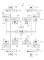
- FIG. 2 is a block diagram for explaining the configuration of the tail sitter type flying object 1 according to the first embodiment.
- the fuselage 20 the four main wings 30a, 30b, 30c, 30d and the like are not shown.
- the tailsitter type vehicle 1 includes a battery 21, a control device 22, four blades 40a, 40b, 40c, 40d, four electric actuators 41a, 41b, 41c, 41d, and four. It includes one inner propeller 50a, 50b, 50c, 50d, eight electric motors 51a, 51b, 51c, 51d, 61a, 61b, 61c, 61d, and four outer propellers 60a, 60b, 60c, 60d.
- the rotor blades 40a, 40b, 40c, 40d and the electric actuators 41a, 41b, 41c, 41d correspond one-to-one, and the propellers 50a, 50b, 50c, 50d, 60a, 60b, 60c, 60d and each electric motor.
- "one-to-one correspondence with electric actuators" for moving blades means that the number of moving blades and the number of electric actuators are the same, and a specific moving blade and a specific electric actuator are used. It means that there is a corresponding relationship.
- "one-to-one correspondence with an electric motor” for a propeller means that the number of propellers and the number of electric motors are the same, and the specific propeller and the specific electric motor correspond to each other. It means that it is in.
- the battery 21 supplies the stored electric power to each component.
- the battery 21 may be rechargeable.
- the control device 22 is connected to a battery 21, four electric actuators 41a, 41b, 41c, 41d, and eight electric motors 51a, 51b, 51c, 51d, 61a, 61b, 61c, 61d.
- the control device 22 includes a power conversion device and the like, and controls each component.
- the four electric actuators 41a, 41b, 41c, 41d are connected to the four blades 40a, 40b, 40c, 40d, respectively.
- the four electric actuators 41a, 41b, 41c, 41d are for moving the four blades 40a, 40b, 40c, 40d, respectively. Electric power is supplied from the control device 22 to the electric actuators 41a, 41b, 41c, and 41d.
- the four electric motors 51a, 51b, 51c, 51d are connected to the four inner propellers 50a, 50b, 50c, 50d, respectively.
- the four electric motors 51a, 51b, 51c and 51d control the rotation speeds of the four inner propellers 50a, 50b, 50c and 50d, respectively. Electric power is supplied to each of the electric motors 51a, 51b, 51c, and 51d from the control device 22.
- the four electric motors 61a, 61b, 61c, 61d are connected to the four outer propellers 60a, 60b, 60c, 60d, respectively.
- the four electric motors 61a, 61b, 61c, 61d control the rotation speeds of the four outer propellers 60a, 60b, 60c, 60d, respectively. Electric power is supplied to each of the electric motors 61a, 61b, 61c, 61d from the control device 22.
- various motors such as a synchronous motor, an induction motor, and a DC commutator motor can be used.
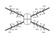
- FIG. 3 is a front view of the tail sitter type flying object 1 according to the first embodiment.
- each propeller 50a, 50c, 60a, 60c is used to offset the counter-torque generated by the rotation of each propeller 50a, 50b, 50c, 50d, 60a, 60b, 60c, 60d.
- the propellers 50b, 50d, 60b, 60d those that rotate in the direction indicated by the arrow A (clockwise in FIG. 3) are adopted, and those that rotate in the direction indicated by the arrow B (counterclockwise in FIG. 3). Can be adopted.
- propellers 50a, 50c, 60a, 60c that rotate in the direction indicated by the arrow B are adopted, and the propellers 50b, 50d, 60b, 60d are the arrows A. It is also possible to adopt the one that rotates in the direction indicated by.
- propellers 50a, 50c, 60b, 60d that rotate in the direction indicated by arrow A are adopted, and propellers 50b, 50d, 60a, 60c are designated as arrow B. It is also possible to adopt the one that rotates in the direction indicated by.
- propellers 50a, 50c, 60b, 60d that rotate in the direction indicated by the arrow B are adopted, and the propellers 50b, 50d, 60a, 60c are the arrows A. It is also possible to adopt the one that rotates in the direction indicated by.
- the two inner propellers 50a and 50b provided on the two main wings 30a and 30b, which are located on the upper side during level flight have opposite rotation directions, respectively.
- the two inner propellers 50c and 50d provided on the two main wings 30c and 30d, which are located on the lower side during level flight have opposite rotation directions, respectively.
- the two outer propellers 60a and 60b provided on the two main wings 30a and 30b, which are located on the upper side during level flight have opposite rotation directions and are located on the lower side during level flight. It is preferable that the two outer propellers 60c and 60d provided on the two main wings 30c and 30d have opposite rotation directions, respectively.
- the two inner propellers 50b and 50c provided on the two main wings 30b and 30c, which are located on the right side in the traveling direction during level flight, are in the rotation direction, respectively.
- the two inner propellers 50a and 50d provided on the two main wings 30a and 30d, which are located on the left side in the traveling direction during level flight, have opposite rotation directions, respectively.
- the two inner propellers 50b and 50c provided on the two main wings 30b and 30c, which are located on the right side in the traveling direction during level flight have the same rotation direction and travel during level flight.
- the two inner propellers 50a and 50d provided on the two main wings 30a and 30d located on the left side in the direction may have the same rotation direction, respectively.
- the two outer propellers 60b and 60c provided on the two main wings 30b and 30c, which are located on the right side in the traveling direction during level flight, are in the rotation direction, respectively.
- the two outer propellers 60a and 60d provided on the two main wings 30a and 30d, which are located on the left side in the traveling direction during level flight, have opposite rotation directions, respectively.
- the two outer propellers 60b and 60c provided on the two main wings 30b and 30c, which are located on the right side in the traveling direction during level flight have the same rotation direction and travel during level flight.
- the two outer propellers 60a and 60d provided on the two main wings 30a and 30d located on the left side in the direction may have the same rotation direction, respectively.
- the tail sitter type flying object 1 it is possible to individually control the rotation speeds of the propellers 50a, 50b, 50c, 50d, 60a, 60b, 60c, and 60d.
- roll control, pitch control, and yaw control can be performed by appropriately controlling the rotation speeds of the propellers 50a, 50b, 50c, 50d, 60a, 60b, 60c, and 60d. That is, in the tail sitter type flying object 1, the rotation speed difference is generated between the rotation speeds of the propellers 50a, 50c, 60a, 60c and the rotation speeds of the propellers 50b, 50d, 60b, 60d, thereby causing the roll. Control is possible.
- the pitch is caused by causing a rotation speed difference between the rotation speeds of the propellers 50a, 50b, 60a, 60b and the rotation speeds of the propellers 50c, 50d, 60c, 60d. Control is possible. Further, in the tail sitter type flying object 1, the yaw is generated by causing a rotation speed difference between the rotation speeds of the propellers 50a, 50d, 60a, 60d and the rotation speeds of the propellers 50b, 50c, 60b, 60c. Control is possible.
- the roll control, pitch control, and yaw control described above can be performed with high accuracy and response. It becomes possible to do it with good sex.
- the tail sitter type flying object 1 it is possible to control the rotation speeds of the inner propellers 50a, 50b, 50c, and 50d to the same number, and individually control the rotation speeds of the outer propellers 60a, 60b, 60c, and 60d. .. Further, in the tail sitter type flying object 1, it is possible to control the rotation speeds of the outer propellers 60a, 60b, 60c, and 60d to the same number, and individually control the rotation speeds of the inner propellers 50a, 50b, 50c, and 50d. ..
- the tail sitter type flying object 1 it is also possible to individually control the rotation speeds of the inner propellers 50a, 50b, 50c, 50d and the outer propellers 60a, 60b, 60c, 60d, respectively.
- the roll control, pitch control, and yaw control described above can be performed with higher accuracy and response. It becomes possible to do it with good sex.
- each electric motor 51a, 51b, 51c, 51d , 61a, 61b, 61c, 61d accurately adjust the rotation speed of each propeller 50a, 50b, 50c, 50d, 60a, 60b, 60c, 60d to an arbitrary rotation speed commanded by the control device 22.
- the rotation speeds of the propellers 50a, 50b, 50c, 50d, 60a, 60b, 60c, and 60d can be controlled with high accuracy and responsiveness. ..
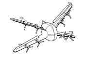
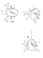
- FIG. 4 is a perspective view seen from the front showing an example of the tail sitter type flying object 1 according to the first embodiment during level flight.
- FIG. 5 is a rear perspective view showing an example of the tail sitter type flying object 1 according to the first embodiment during level flight.
- each of the moving blades 40a, 40b, 40c, and 40d can be moved upward when viewed from the nose during level flight, as shown in FIG. In addition, it is possible to move each blade 40a, 40b, 40c, 40d downward when viewed from the nose during level flight.
- the moving directions of the moving blades 40a, 40b, 40c, and 40d can be individually controlled.
- the degree of movement (size, speed) of each of the moving blades 40a, 40b, 40c, and 40d can be individually controlled.
- FIG. 6 is a diagram for explaining an example from takeoff to landing of the tailsitter type aircraft 1 according to the first embodiment.
- the tailsitter type aircraft 1 takes off and rises by rotating each propeller 50a, 50b, 50c, 50d, 60a, 60b, 60c, 60d at a predetermined rotation speed.
- the rotation speed of each propeller 50a, 50b, 60a, 60b is higher than the rotation speed of each propeller 50c, 50d, 60c, 60d. Make it larger (pitch control) and change the attitude of the aircraft by about 90 degrees.
- the tail sitter type aircraft 1 may make the rotation speed of each propeller 50c, 50d, 60c, 60d smaller than the rotation speed of each propeller 50a, 50b, 60a, 60b, and shift the attitude of the aircraft by about 90 degrees. .. [3] During horizontal flight Next, the tailsitter type flying object 1 makes horizontal flight by rotating each propeller 50a, 50b, 50c, 50d, 60a, 60b, 60c, 60d at a predetermined rotation speed.
- the tailsitter type flying object 1 can accelerate or decelerate by increasing or decreasing the rotation speed of each propeller 50a, 50b, 50c, 50d, 60a, 60b, 60c, 60d, and each propeller 50a, 50b, Roll control, pitch control, and yaw control can be performed by increasing or decreasing the individual rotation speeds of 50c, 50d, 60a, 60b, 60c, and 60d.
- the inner propellers 50a, 50b, 50c, 50d are rotated mainly for obtaining propulsive force, and the outer propellers 60a, 60b, 60c, respectively.
- the 60d may be rotated primarily for roll control, pitch control and yaw control, or the outer propellers 60a, 60b, 60c, 60d may be rotated primarily for propulsion during level flight.
- the inner propellers 50a, 50b, 50c, 50d may be rotated mainly for roll control, pitch control, and yaw control.
- the tail sitter type flying object 1 can be raised or lowered by increasing or decreasing the rotation speed of each propeller 50a, 50b, 50c, 50d, 60a, 60b, 60c, 60d, and each propeller 50a. , 50b, 50c, 50d, 60a, 60b, 60c, 60d By increasing or decreasing the individual rotation speeds, roll control, pitch control and yaw control can be performed, and movement in the horizontal direction becomes possible. .. In this case, the tailsitter type flying object 1 has an effect that lift can be obtained from the four main wings 30a, 30b, 30c, and 30d connected to the fuselage 20 in an X-shape in front view.
- the rotation speed of each propeller 50c, 50d, 60c, 60d is made larger than the rotation speed of each propeller 50a, 50b, 60a, 60b to make the aircraft body.
- the attitude of the aircraft is changed by a predetermined angle (an angle greater than 0 degrees and less than 90 degrees) and the rotation speeds of the propellers 50a, 50b, 50c, 50d, 60a, 60b, 60c, and 60d are controlled. It is also possible to fly from ultra-low speed to high speed from aerial stop.
- each propeller 50c, 50d, 60c, 60d is made larger than the rotation speed of each propeller 50a, 50b, 60a, 60b to make the aircraft body. Hovering is also possible by balancing the thrust and the weight of the aircraft by changing the attitude of about 90 degrees and controlling the rotation speed of each propeller 50a, 50b, 50c, 50d, 60a, 60b, 60c, 60d. ..
- the rotation speed of each propeller 50c, 50d, 60c, 60d is made larger than the rotation speed of each propeller 50a, 50b, 60a, 60b to make the aircraft body.
- the attitude of the aircraft is changed by a predetermined angle (greater than 90 degrees and less than 180 degrees) and the rotation speed of each propeller 50a, 50b, 50c, 50d, 60a, 60b, 60c, 60d is controlled. It is also possible to fly backward from ultra-low speed to high speed from aerial stop.
- the rotation speed of each propeller 50c, 50d, 60c, 60d is set to be larger than the rotation speed of each propeller 50a, 50b, 60a, 60b. It is also possible to shift the attitude to about 180 degrees and shift to back flight.
- roll control, pitch control, and yaw control which are more accurate and responsive than the conventional ones, can be performed even during these flights.
- the tail sitter type flying object 1 it is possible to obtain sufficient propulsive force and ascending force by the eight propellers 50a, 50b, 50c, 50d, 60a, 60b, 60c, and 60d even during these flights. Further, in the tail sitter type flying object 1, eight propellers 50a, 50b, 50c, 50d, 60a, 60b, 60c, 60d are provided in a front view X shape even during these flights, so that each propeller It is possible to make the moments of forces of 50a, 50b, 50c, 50d, 60a, 60b, 60c, 60d highly symmetric and to have high maneuvering stability.
- tail-sitter type air vehicle 1 According to the tail-sitter type air vehicle 1 according to the first embodiment, four main wings 30a, 30b, 30c, 30d and four main wings 30a connected to the fuselage 20 in a front view X shape, respectively. , 30b, 30c, 30d, respectively, with eight propellers 50a, 50b, 50c, 50d, 60a, 60b, 60c, 60d and eight propellers 50a, 50b, for obtaining lift or propulsion.
- Eight electric motors that have a one-to-one correspondence with 50c, 50d, 60a, 60b, 60c, and 60d, respectively, and control the rotation speeds of the eight propellers 50a, 50b, 50c, 50d, 60a, 60b, 60c, and 60d, respectively. It is equipped with 51a, 51b, 51c, 51d, 61a, 61b, 61c, 61d, and eight propellers 50a, 50b, 50c, 50d, 60a, 60b, 60c, 60d are four main wings 30a, 30b, 30c, 30d.
- the four inner propellers 50a, 50b, 50c, 50d provided inside each leading edge and the four outer propellers 60a, provided outside the respective leading edges of the four main wings 30a, 30b, 30c, 30d. Since it is composed of 60b, 60c, and 60d, it is possible to perform roll control, pitch control, and yaw control with higher accuracy and better responsiveness than before.
- the two inner propellers 50a and 50c and the two outer propellers 60a and 60c provided on the two main wings 30a and 30c on the upper right side and the lower left side in the front view during level flight.
- Rotation speed between the rotation speed of the two inner propellers 50b and 50d and the rotation speeds of the two outer propellers 60b and 60d provided on the two main wings 30b and 30d on the upper left side and the lower right side of the front view during level flight By making a difference, the roll control described above is possible during vertical flight, horizontal flight and hovering.
- the rotational speeds of the two inner propellers 50a and 50b and the two outer propellers 60a and 60b provided on the two main wings 30a and 30b on the upper side of the front view during level flight are horizontal.
- the pitch described above is created by creating a rotation speed difference between the rotation speeds of the two inner propellers 50c and 50d and the two outer propellers 60c and 60d provided on the two main wings 30c and 30d on the lower front view during flight. Control is possible during vertical flight, level flight and hovering.
- the rotation speeds of the two inner propellers 50a and 50d and the two outer propellers 60a and 60d provided on the two main wings 30a and 30d on the right side of the front view during level flight As described above, by creating a rotation speed difference between the rotation speeds of the two inner propellers 50b and 50c and the two outer propellers 60b and 60c provided on the two main wings 30b and 30c on the left side of the front view during level flight. Yaw control is possible during vertical flight, level flight and hovering.
- the roll control described above is performed by appropriately controlling the rotation speeds of the eight propellers 50a, 50b, 50c, 50d, 60a, 60b, 60c, and 60d, respectively.
- Pitch control and yaw control can be performed with high accuracy and responsiveness.
- the two inner propellers 50a and 50b provided on the two main wings 30a and 30b, which are located on the upper side during level flight, have different rotation directions, respectively. If the two inner propellers 50c and 50d provided on the two main wings 30c and 30d, which are opposite and will be located on the lower side during level flight, have opposite rotation directions, the inner propellers 50a , 50b, 50c, 50d can cancel out the anti-torque generated by the rotation. As a result, the flight of the aircraft is stabilized, and more accurate and responsive roll control, pitch control and yaw control become possible.
- the two outer propellers 60a and 60b provided on the two main wings 30a and 30b, which are located on the upper side during level flight, have different rotation directions, respectively. If the two outer propellers 60c and 60d provided on the two main wings 30c and 30d, which are opposite and will be located on the lower side during level flight, have opposite rotation directions, the outer propellers 60a , 60b, 60c, 60d can cancel the anti-torque generated by the rotation. As a result, the flight of the aircraft is stabilized, and more accurate and responsive roll control, pitch control and yaw control become possible.
- the roll control can also be performed by appropriately controlling the rotor blades 40a, 40b, 40c, and 40d. Since pitch control and yaw control can be performed, roll control, pitch control, and yaw control with higher accuracy and better responsiveness become possible.
- the fuselage 20 has an egg shape in which the traveling direction of the fuselage is long as in the tail sitter type flying body 1 according to the first embodiment, it is possible to reduce the air resistance of the fuselage during flight.
- the four main wings 30a, 30b, 30c, and 30d are provided. As a result, during level flight, it is possible to perform a flight operation using sufficient lift obtained from each of the main wings 30a, 30b, 30c, and 30d.
- the propellers 50a, 50b, 50c, 50d, 60a, 60b, 60c, and 60d are arranged apart from each other, it is suitable for hovering and fine movement. It is possible to make a suitable tailsitter type air vehicle 1.
- the four main wings 30a, 30b, 30c, and 30d are connected to the fuselage 20 in an X-shape in front view.
- the size of the fuselage 20 can be minimized, and it is possible to eliminate the need to provide the fuselage 20 with a structure for fixing the main wings to the fuselage 20.
- each propeller 50a using the electric motors 51a, 51b, 51c, 51d, 61a, 61b, 61c, 61d having excellent output control responsiveness, Since it is possible to control the rotation speeds of 50b, 50c, 50d, 60a, 60b, 60c, and 60d, the rotation speeds of the propellers 50a, 50b, 50c, 50d, 60a, 60b, 60c, and 60d can be precisely and smoothly controlled. Can be controlled.
- roll control, pitch control and yaw control are performed by increasing or decreasing the individual rotation speeds of the propellers 50a, 50b, 50c, 50d, 60a, 60b, 60c, 60d. Since it is possible to perform control, it is not necessary to provide a horizontal stabilizer, a vertical stabilizer, an elevator, a rudder, and the like, and as a result, it is possible to reduce the air resistance of the airframe.
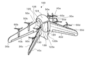
- FIG. 7 is a perspective view of the tail sitter type flying object 100 according to the second embodiment.
- the tail sitter type aircraft 100 according to the second embodiment is a so-called manned vertical take-off and landing aircraft.
- the tail sitter type aircraft 100 according to the second embodiment basically has the same configuration as the tail sitter type aircraft 1 according to the first embodiment, but the fuselage configuration is the same as the tail sitter type aircraft 1 according to the first embodiment. different.
- the tailsitter type air vehicle 100 includes a fuselage 120, four main wings 30a, 30b, 30c, 30d, four moving blades 40a, 40b, 40c, 40d, and four blades. It includes inner propellers 50a, 50b, 50c, 50d and four outer propellers 60a, 60b, 60c, 60d.
- the four main wings 30a, 30b, 30c, and 30d are separated from each other and connected to the fuselage 120 in a front view X shape.
- the fuselage 120 is an egg shape in which the traveling direction of the fuselage is longitudinal.
- the body 120 shown in FIG. 7 has an egg shape in which the traveling direction of the body is longitudinal, but the shape of the body 120 is not limited to the egg shape.
- the fuselage 120 may have a spherical shape or a pointed nose.
- the fuselage 120 is the base of the four main wings 30a, 30b, 30c, 30d.
- the body 120 houses a battery 121 and the like, which will be described later.
- the fuselage 120 has an in-flight space 134 described later inside.
- the fuselage 120 has lower window portions 123a and 123b located on the lower side during level flight of the fuselage.
- the passenger H which will be described later, can board the cabin space 134 by opening the lower window portions 123a and 123b.
- the fuselage 120 has a front window portion 124 located on the front side during level flight of the fuselage.
- the fuselage 120 has an upper window portion 125 located on the upper side during level flight of the fuselage.
- the fuselage 120 has a right window portion 126 located on the right side of the fuselage during level flight and a left window portion (not shown) located on the left side.
- the fuselage 120 includes an upper pillar portion (not shown) that connects the adjacent main wings 30a and the main wings 30b, a lower pillar portion 128 that connects the adjacent main wings 30c and the main wings 30d, and adjacent main wings 30b and the main wings 30c. It has a right-side pillar portion 130 that connects between the two pillars, and a left-side pillar portion (not shown) that connects the adjacent main wings 30a and the main wings 30d.
- FIG. 8 is a block diagram for explaining the configuration of the tail sitter type flying object 100 according to the second embodiment.
- the fuselage 120, the four main wings 30a, 30b, 30c, 30d, etc. are not shown.
- the tailsitter type air vehicle 100 includes a battery 121, a control device 122, a seat 132, an electric motor 133, four blades 40a, 40b, 40c, 40d, and four electric actuators 41a. , 41b, 41c, 41d, four inner propellers 50a, 50b, 50c, 50d, eight electric motors 51a, 51b, 51c, 51d, 61a, 61b, 61c, 61d and four outer propellers 60a, 60b, 60c and 60d are provided.
- the battery 121 supplies the stored electric power to each component.
- the capacity of the battery 121 is much larger than the capacity of the battery 21 of the first embodiment.
- the battery 121 may be rechargeable.
- the control device 122 is connected to a battery 121, an electric motor 133, four electric actuators 41a, 41b, 41c, 41d, and eight electric motors 51a, 51b, 51c, 51d, 61a, 61b, 61c, 61d. There is.
- the control device 122 includes a power conversion device and the like, and controls each component.
- the seat 132 is connected to the electric motor 133.
- the seat 132 is provided in the cabin space 134.
- Passenger H which will be described later, is seated on the seat 132.
- the seat 132 includes a link mechanism.
- the electric motor 133 is connected to the seat 132.
- the electric motor 133 transmits the rotational force to the seat 132.
- Electric power is supplied to the electric motor 133 from the control device 122.
- As the electric motor 133 a geared motor can be used.
- FIG. 9 is a diagram for explaining an example from takeoff to level flight of the tailsitter type flying object 100 according to the second embodiment.
- FIG. 10 is a diagram for explaining an example from level flight to landing of the tail sitter type aircraft 100 according to the second embodiment.
- the rotation speed of each propeller 50c, 50d, 60c, 60d may be made smaller than the rotation speed of each propeller 50a, 50b, 60a, 60b, and the attitude of the aircraft may be changed by about 90 degrees. ..
- the seat 132 is tilted in the direction indicated by the arrow C.
- the seat 132 is tilted so that the passenger H seated on the seat 132 faces in the horizontal direction.
- the tailsitter type flying object 1 makes horizontal flight by rotating each propeller 50a, 50b, 50c, 50d, 60a, 60b, 60c, 60d at a predetermined rotation speed.
- the seat 132 is further tilted in the direction indicated by the arrow C, and the sheet 132 is extended in the direction indicated by the arrow D accordingly (by the link mechanism).
- the rotation speeds of the propellers 50c, 50d, 60c, and 60d are set to the rotation speeds of the propellers 50a, respectively.
- the attitude of the aircraft is changed by about 90 degrees by making it larger than the rotation speeds of 50b, 60a, and 60b (pitch control).
- the tail sitter type aircraft 100 may make the rotation speed of each propeller 50a, 50b, 60a, 60b smaller than the rotation speed of each propeller 50c, 50d, 60c, 60d, and shift the attitude of the aircraft by about 90 degrees. ..
- the seat 132 is tilted in the direction indicated by the arrow E, and the seat 132 is bent in the direction indicated by the arrow F accordingly (by the link mechanism).
- the tailsitter type aircraft 100 descends and lands by gradually reducing the rotational speeds of the propellers 50a, 50b, 50c, 50d, 60a, 60b, 60c, and 60d.
- the tail-sitter type aircraft 100 according to the second embodiment has a body configuration different from that of the tail-sitter type 1 according to the first embodiment, but has four main wings 30a, which are connected to the body 120 in an X-shape in a front view.
- Eight propellers 50a, 50b, 50c, 50d, 60a, 60b, 60c are provided on each of the 30b, 30c, 30d and the four main wings 30a, 30b, 30c, 30d to obtain lift or propulsion.
- the fuselage 120 has an in-flight space 134 inside, and a seat 132 that tilts according to the attitude of the aircraft is provided in the in-flight space 134, and the seat 132 is provided. Since the passenger H seated on the seat 132 is tilted so as to face in the horizontal direction, it is as simple as tilting only the seat 132 on which the passenger H is seated even when there is a change in the attitude of the aircraft. It is possible to secure the visibility of the occupant H and reduce the burden on the occupant with a lightweight and compact mechanism.
- the traveling direction of the fuselage 120 is longitudinal. Even in the case of the egg shape, it is possible to eliminate the inconvenience that the head of the passenger H hits the upper part of the cabin when the seat 132 is tilted.
- the four main wings 30a, 30b, 30c, and 30d are separated from each other and connected to the body 120, and the body 120 is placed on the lower side of the body during horizontal flight.
- the lower window portions 123a and 123b located, the right window portion 126 located on the right side during horizontal flight of the aircraft, the left window portion (not shown) located on the left side during horizontal flight of the aircraft, and the adjacent main wings are connected. Since it has pillar portions 128, 130, etc., it is possible to secure a wide field of view of the passenger H during vertical flight, horizontal flight, and hovering of the aircraft. Further, since it is not necessary to separately provide a structure for connecting adjacent main wings, it is possible to reduce the weight of the airframe and increase the strength of the airframe.
- the tail sitter type aircraft 100 according to the second embodiment has the same configuration as the tail sitter type aircraft 1 according to the first embodiment except for the configuration of the fuselage, the effect of the tail sitter type aircraft 1 according to the first embodiment is obtained. Of these, it also has the corresponding effect.
- the number of propellers is eight, but the present invention is not limited to this.
- the number of propellers may be greater than eight.
- the number of propellers is preferably a multiple of 4 because they are arranged symmetrically.
- the tail sitter type flying object may be capable of individually controlling the rotation direction of each propeller.
- the tail sitter type air vehicle is provided with a tilting seat driven by, for example, a geared motor in the cabin space, but the present invention is not limited to this.
- a seat having a structure of hanging from a support or the like, such as a so-called swing may be provided in the cabin space.
- the seat can be tilted by using gravity by moving the support column or the like according to the posture of the machine body.
- FIG. 11 is a block diagram for explaining a configuration of a modified example of the tail sitter type flying object 100 according to the second embodiment.
- the tailsitter type flying object 100A further includes a sensor 135.
- the sensor 135 is a posture sensor that detects a change in the posture of the airframe. If the sensor 135 for detecting the attitude change of the airframe is provided as in this modification, it is possible to accurately detect the attitude change of the airframe.
- 1,100,100A ... tail sitter type flying object 20,120 ... fuselage, 21,121 ... battery, 22,122 ... control device, 30a, 30b, 30c, 30d ... main wing, 40a, 40b, 40c, 40d ... moving blade , 41a, 41b, 41c, 41d ... Electric actuator, 50a, 50b, 50c, 50d ... Inner propeller, 51a, 51b, 51c, 51d, 61a, 61b, 61c, 61d, 133 ... Electric motor, 60a, 60b, 60c, 60d ... outer propeller, 123a, 123b ... lower window, 124 ... front window, 125 ... upper window, 126 ... right window, 128 ... lower pillar, 130 ... right pillar, 132 ... seat, 134 ... cabin space, 135 ... sensor
Landscapes
- Engineering & Computer Science (AREA)
- Aviation & Aerospace Engineering (AREA)
- Toys (AREA)
Abstract
Le but de la présente invention est de fournir un aéronef à décollage vertical capable d'un contrôle en roulis, d'une commande de pas et d'une commande de lacet présentant une précision et une réactivité plus élevées que de manière classique. Un aéronef à décollage vertical (1) est pourvu : d'un corps (20) ; de quatre ailes principales (30a, etc.) reliées au corps (20) en forme de X lorsqu'elles sont vues depuis l'avant ; de huit hélices (50a, etc.), deux étant disposées sur chacune des quatre ailes principales (30a, etc.) et qui servent à fournir une portance ou une propulsion ; et de huit moteurs électriques (51a, etc.) qui correspondent un à un aux huit hélices (50a, etc.) et qui commandent les vitesses de rotation des huit hélices (50a, etc.) correspondantes. Les huit hélices (50a, etc.) sont conçues de telle sorte que quatre hélices internes (50a, etc.) sont respectivement disposées sur les côtés intérieurs des parties de bord avant des quatre ailes principales (30a, etc.) et de telle sorte que quatre hélices externes (60a, etc.) sont respectivement disposées sur les côtés extérieurs des parties de bord avant des quatre ailes principales (30a, etc.).
Priority Applications (3)
| Application Number | Priority Date | Filing Date | Title |
|---|---|---|---|
| PCT/JP2019/009836 WO2020183594A1 (fr) | 2019-03-11 | 2019-03-11 | Aéronef à décollage vertical |
| PCT/JP2019/011951 WO2020183739A1 (fr) | 2019-03-11 | 2019-03-21 | Aéronef à décollage et atterrissage verticaux |
| JP2021600187U JP3236741U (ja) | 2019-03-11 | 2019-03-21 | テールシッタ式飛行体 |
Applications Claiming Priority (1)
| Application Number | Priority Date | Filing Date | Title |
|---|---|---|---|
| PCT/JP2019/009836 WO2020183594A1 (fr) | 2019-03-11 | 2019-03-11 | Aéronef à décollage vertical |
Publications (1)
| Publication Number | Publication Date |
|---|---|
| WO2020183594A1 true WO2020183594A1 (fr) | 2020-09-17 |
Family
ID=72426677
Family Applications (2)
| Application Number | Title | Priority Date | Filing Date |
|---|---|---|---|
| PCT/JP2019/009836 Ceased WO2020183594A1 (fr) | 2019-03-11 | 2019-03-11 | Aéronef à décollage vertical |
| PCT/JP2019/011951 Ceased WO2020183739A1 (fr) | 2019-03-11 | 2019-03-21 | Aéronef à décollage et atterrissage verticaux |
Family Applications After (1)
| Application Number | Title | Priority Date | Filing Date |
|---|---|---|---|
| PCT/JP2019/011951 Ceased WO2020183739A1 (fr) | 2019-03-11 | 2019-03-21 | Aéronef à décollage et atterrissage verticaux |
Country Status (2)
| Country | Link |
|---|---|
| JP (1) | JP3236741U (fr) |
| WO (2) | WO2020183594A1 (fr) |
Cited By (1)
| Publication number | Priority date | Publication date | Assignee | Title |
|---|---|---|---|---|
| DE102024103724A1 (de) * | 2024-02-09 | 2025-08-14 | Deutsches Zentrum für Luft- und Raumfahrt e.V. | Unbemanntes Luftfahrzeug und dessen Verwendung |
Citations (6)
| Publication number | Priority date | Publication date | Assignee | Title |
|---|---|---|---|---|
| US20160144957A1 (en) * | 2014-11-26 | 2016-05-26 | XCraft Enterprises, LLC | High speed multi-rotor vertical takeoff and landing aircraft |
| JP2016517821A (ja) * | 2013-05-03 | 2016-06-20 | エアロバイロメント, インコーポレイテッドAerovironment, Inc. | 垂直離着陸(vtol)航空機 |
| CN205440867U (zh) * | 2015-12-30 | 2016-08-10 | 崔浩 | 一种可倾转机翼飞机 |
| WO2017200610A1 (fr) * | 2016-05-18 | 2017-11-23 | Airbus Group Hq, Inc. | Aéronef autopiloté pour le transport de passagers ou de marchandises |
| US20180002011A1 (en) * | 2016-07-01 | 2018-01-04 | Bell Helicopter Textron Inc. | Aircraft with Selectively Attachable Passenger Pod Assembly |
| US20180354615A1 (en) * | 2017-06-12 | 2018-12-13 | Bell Helicopter Textron Inc. | X-Tiltwing Aircraft |
Family Cites Families (2)
| Publication number | Priority date | Publication date | Assignee | Title |
|---|---|---|---|---|
| JPH11237582A (ja) * | 1998-02-19 | 1999-08-31 | Mitsubishi Precision Co Ltd | 航空機搭載用模擬視界装置 |
| US20050278753A1 (en) * | 2004-02-17 | 2005-12-15 | Thales Avionics, Inc. | Broadcast passenger flight information system and method for using the same |
-
2019
- 2019-03-11 WO PCT/JP2019/009836 patent/WO2020183594A1/fr not_active Ceased
- 2019-03-21 WO PCT/JP2019/011951 patent/WO2020183739A1/fr not_active Ceased
- 2019-03-21 JP JP2021600187U patent/JP3236741U/ja active Active
Patent Citations (6)
| Publication number | Priority date | Publication date | Assignee | Title |
|---|---|---|---|---|
| JP2016517821A (ja) * | 2013-05-03 | 2016-06-20 | エアロバイロメント, インコーポレイテッドAerovironment, Inc. | 垂直離着陸(vtol)航空機 |
| US20160144957A1 (en) * | 2014-11-26 | 2016-05-26 | XCraft Enterprises, LLC | High speed multi-rotor vertical takeoff and landing aircraft |
| CN205440867U (zh) * | 2015-12-30 | 2016-08-10 | 崔浩 | 一种可倾转机翼飞机 |
| WO2017200610A1 (fr) * | 2016-05-18 | 2017-11-23 | Airbus Group Hq, Inc. | Aéronef autopiloté pour le transport de passagers ou de marchandises |
| US20180002011A1 (en) * | 2016-07-01 | 2018-01-04 | Bell Helicopter Textron Inc. | Aircraft with Selectively Attachable Passenger Pod Assembly |
| US20180354615A1 (en) * | 2017-06-12 | 2018-12-13 | Bell Helicopter Textron Inc. | X-Tiltwing Aircraft |
Cited By (2)
| Publication number | Priority date | Publication date | Assignee | Title |
|---|---|---|---|---|
| DE102024103724A1 (de) * | 2024-02-09 | 2025-08-14 | Deutsches Zentrum für Luft- und Raumfahrt e.V. | Unbemanntes Luftfahrzeug und dessen Verwendung |
| DE102024103724B4 (de) * | 2024-02-09 | 2025-08-21 | Deutsches Zentrum für Luft- und Raumfahrt e.V. | Unbemanntes Luftfahrzeug und dessen Verwendung |
Also Published As
| Publication number | Publication date |
|---|---|
| WO2020183739A1 (fr) | 2020-09-17 |
| JP3236741U (ja) | 2022-03-14 |
Similar Documents
| Publication | Publication Date | Title |
|---|---|---|
| US10144509B2 (en) | High performance VTOL aircraft | |
| CN111605708B (zh) | 偏转翼飞行器 | |
| AU2018200729B2 (en) | Vertical takeoff and landing (VTOL) air vehicle | |
| EP2353684B1 (fr) | Avion de modèle VTOL (décollage et atterrissage vertical) | |
| US11117657B2 (en) | Aeronautical apparatus | |
| AU2015374294B2 (en) | Rotary wing VTOL with fixed wing forward flight mode | |
| US20200010182A1 (en) | Pivoting wing system for vtol aircraft | |
| KR102758509B1 (ko) | 테일 시터 | |
| KR102135285B1 (ko) | 수직 이착륙 고정익 무인기 | |
| WO2016028358A2 (fr) | Aéronef vtol à hautes performances | |
| KR100812756B1 (ko) | 요잉제어가 용이한 쿼드로콥터 | |
| CN111479751B (zh) | 具有可调翼的混合多旋翼无人航空器 | |
| WO2017007915A1 (fr) | Aéronef | |
| EP3730404A1 (fr) | Aeronef capable de decoller verticalement et son procede de commande | |
| JP2019026236A (ja) | 垂直離着陸機 | |
| JP2018086916A (ja) | 飛行体 | |
| JP2018020742A (ja) | 飛行体、改造キット、制御方法及び制御プログラム | |
| WO2018187844A1 (fr) | Aéronef à double mode de vol | |
| Bogdanowicz et al. | Development of a quad-rotor biplane MAV with enhanced roll control authority in fixed wing mode | |
| JP3236741U (ja) | テールシッタ式飛行体 | |
| EP3736211B1 (fr) | Système et procédé permettant d'améliorer la commande d'altitude d'un autogyre | |
| KR20250065974A (ko) | 양력 조절 가능한 고정익을 구비하는 멀티로터 드론 | |
| CN114987737A (zh) | 尾部主动变距涵道推进无人飞行器 | |
| CN120096804A (zh) | 一种叠层倾转旋翼结构的飞行器及控制方法 | |
| HK40029322B (zh) | 偏转翼飞行器 |
Legal Events
| Date | Code | Title | Description |
|---|---|---|---|
| 121 | Ep: the epo has been informed by wipo that ep was designated in this application |
Ref document number: 19919238 Country of ref document: EP Kind code of ref document: A1 |
|
| NENP | Non-entry into the national phase |
Ref country code: DE |
|
| 122 | Ep: pct application non-entry in european phase |
Ref document number: 19919238 Country of ref document: EP Kind code of ref document: A1 |
|
| NENP | Non-entry into the national phase |
Ref country code: JP |