WO2020184632A1 - Dispositif de pesée par combinaison - Google Patents
Dispositif de pesée par combinaison Download PDFInfo
- Publication number
- WO2020184632A1 WO2020184632A1 PCT/JP2020/010641 JP2020010641W WO2020184632A1 WO 2020184632 A1 WO2020184632 A1 WO 2020184632A1 JP 2020010641 W JP2020010641 W JP 2020010641W WO 2020184632 A1 WO2020184632 A1 WO 2020184632A1
- Authority
- WO
- WIPO (PCT)
- Prior art keywords
- support
- hopper
- locking member
- weighing device
- combination weighing
- Prior art date
- Legal status (The legal status is an assumption and is not a legal conclusion. Google has not performed a legal analysis and makes no representation as to the accuracy of the status listed.)
- Ceased
Links
Images



Classifications
-
- G—PHYSICS
- G01—MEASURING; TESTING
- G01G—WEIGHING
- G01G19/00—Weighing apparatus or methods adapted for special purposes not provided for in the preceding groups
- G01G19/387—Weighing apparatus or methods adapted for special purposes not provided for in the preceding groups for combinatorial weighing, i.e. selecting a combination of articles whose total weight or number is closest to a desired value
-
- G—PHYSICS
- G01—MEASURING; TESTING
- G01G—WEIGHING
- G01G19/00—Weighing apparatus or methods adapted for special purposes not provided for in the preceding groups
- G01G19/387—Weighing apparatus or methods adapted for special purposes not provided for in the preceding groups for combinatorial weighing, i.e. selecting a combination of articles whose total weight or number is closest to a desired value
- G01G19/393—Weighing apparatus or methods adapted for special purposes not provided for in the preceding groups for combinatorial weighing, i.e. selecting a combination of articles whose total weight or number is closest to a desired value using two or more weighing units
-
- B—PERFORMING OPERATIONS; TRANSPORTING
- B65—CONVEYING; PACKING; STORING; HANDLING THIN OR FILAMENTARY MATERIAL
- B65D—CONTAINERS FOR STORAGE OR TRANSPORT OF ARTICLES OR MATERIALS, e.g. BAGS, BARRELS, BOTTLES, BOXES, CANS, CARTONS, CRATES, DRUMS, JARS, TANKS, HOPPERS, FORWARDING CONTAINERS; ACCESSORIES, CLOSURES, OR FITTINGS THEREFOR; PACKAGING ELEMENTS; PACKAGES
- B65D88/00—Large containers
- B65D88/26—Hoppers, i.e. containers having funnel-shaped discharge sections
-
- B—PERFORMING OPERATIONS; TRANSPORTING
- B65—CONVEYING; PACKING; STORING; HANDLING THIN OR FILAMENTARY MATERIAL
- B65G—TRANSPORT OR STORAGE DEVICES, e.g. CONVEYORS FOR LOADING OR TIPPING, SHOP CONVEYOR SYSTEMS OR PNEUMATIC TUBE CONVEYORS
- B65G65/00—Loading or unloading
- B65G65/30—Methods or devices for filling or emptying bunkers, hoppers, tanks, or like containers, of interest apart from their use in particular chemical or physical processes or their application in particular machines, e.g. not covered by a single other subclass
- B65G65/34—Emptying devices
-
- G—PHYSICS
- G01—MEASURING; TESTING
- G01G—WEIGHING
- G01G13/00—Weighing apparatus with automatic feed or discharge for weighing-out batches of material
- G01G13/16—Means for automatically discharging weigh receptacles under control of the weighing mechanism
- G01G13/18—Means for automatically discharging weigh receptacles under control of the weighing mechanism by valves or flaps in the container bottom
Definitions
- the present invention relates to a combination weighing device.
- Patent Document 1 describes a combination weighing device including a plurality of hoppers for temporarily storing articles.
- each hopper is detachably attached to a support provided with a drive unit.
- the hoppers are arranged apart in the vertical direction and have four hooks arranged apart in the width direction. The hopper is attached to the support by hooking each of the four hooks on the support.
- One aspect of the present invention is to provide a combination weighing device capable of improving the mounting workability of the hopper.
- the combination weighing device includes a hopper for temporarily retaining the article and discharging the article, and a support for detachably supporting the hopper, and the hopper is a main body for retaining the article. It has a portion and a mounting portion for attaching the main body portion to the support, and the mounting portion includes a first member extending along the width direction of the main body portion and an article in the main body portion rather than the first member.
- the support has a mounted portion to which the mounting portion of the hopper is mounted, and the mounted portion is At the mounting position where the hopper is attached to the support, the first ruler that defines the position of the first member, the second ruler that defines the position of the second member, and the first ruler in the height direction of the support.
- the hopper is swung toward the support body with the first member as the center in a state where the support portion is arranged between the first member and the second defining portion and can support the first member and the first member is supported by the support portion.
- a guide unit that is arranged on the track of the second member at the time of the invention and guides the second member so that the second member moves downward in the height direction from the position on the track and is located at the second specified portion. And have.
- the mounting portion of the hopper has a first member and a second member.
- the second member is arranged on the main body portion upstream of the first member in the moving direction of the article. That is, in the hopper, the first member is arranged on the lower side and the second member is arranged on the upper side.
- the hopper In a state where the first member is supported by the support portion, the hopper is swung toward the support body with the first member as the center. As a result, the second member moves to the guide portion. Then, when the second member reaches the guide portion and comes into contact with the guide portion, the hopper can be swung toward the support body with the second member as the center, and when the hopper is further swung, the support of the first member in the support portion is supported. Is released. As a result, the hopper can be moved in the height direction. Therefore, by moving the second member along the guide portion, the second member is located at the second defined portion. When the support in the support portion is released, the first member is located in the first regulation portion arranged below the support portion.
- the hopper can be attached to the support.
- the hopper can be attached to the support while maintaining the positional relationship between the attachment portion of the hopper and the attachment portion of the support. Therefore, in the combination weighing device, the workability of attaching the hopper can be improved.
- the guide portion has an inclined surface that inclines downward with respect to the horizontal direction, and the inclined surface may incline toward a direction away from the support in the horizontal direction. In this configuration, when the second member is moved along the inclined surface, the first member moves in the direction away from the support portion, so that the support of the first member in the support portion can be released more reliably.
- the guide portion has a recess provided at the upper end of the inclined surface and arranged at a position on the track of the second member, and the distance between the support portion and the recess is the first of the hopper. It may be equal to the distance between the first member and the second member. In this configuration, the support of the first member in the support portion can be more reliably released by swinging the hopper toward the support body side with the second member as the center in the recess.
- the attached portion is arranged at a position below the track of the second member in the height direction and in the horizontal direction of the guide portion away from the support, and the second member is placed on the second member. 2 It is possible to guide the specified portion and have an inclined portion that is inclined upward with respect to the horizontal direction, and the inclined portion may be inclined toward a direction away from the support in the horizontal direction. In this configuration, the second member can be guided with respect to the second specified portion by the guide portion and the inclined portion. Therefore, the second member can be reliably positioned in the second specified portion.
- the inclined portion inclines upward in the direction away from the support in the horizontal direction. Therefore, the entrance of the second member to the second regulation portion becomes wider. As a result, the second member can be more reliably positioned at the second specified portion.
- the attached portion has a first support member and a second support member arranged to face each other in the width direction, and each of the first support member and the second support member is a first specified portion. It has a second regulation portion, a support portion, and a guide portion, and the distance between the first support member and the second support member in the width direction may be shortened from the support portion toward the upper side.
- the first member is brought closer to the support while checking (visually) the support, and the support is made to support the first member.
- the mounted portion may be looked down, making it difficult for the operator to see the support portion. In this case, it may not be easy to support the first member by the support portion.
- the distance between the first support member provided with the support portion and the second support member in the width direction becomes shorter from the support portion toward the upper side. That is, the width of the portion of the mounted portion above the support portion becomes narrower.
- the upper portion of the first support member and the second support member does not block the field of view, so that the support portion can be confirmed. Therefore, in the combination weighing device, the first member can be brought closer to the support portion while checking the support portion, and the support portion can support the first member. As a result, the workability of attaching the hopper can be improved.
- the hopper is a weighing hopper
- the attached portion of the support may support the weighing hopper.
- the weighing hopper is located below the pool hopper. Therefore, the position of the attached portion that supports the measuring hopper can be a position that the operator looks down on. Therefore, in the mounted portion that supports the measuring hopper, it is particularly effective to reduce the distance between the first support member and the second support member in the width direction from the support portion toward the upper side.
- the hopper mounting workability can be improved.
- FIG. 1 is a configuration diagram of a combination weighing device according to an embodiment.
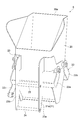
- FIG. 2 is a perspective view showing a pool hopper.
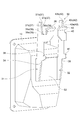
- FIG. 3 is a perspective view showing the mounted portion.
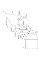
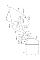
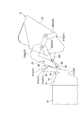
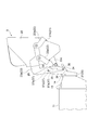
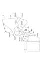
- FIG. 4 is a diagram illustrating a method of attaching the pool hopper.
- FIG. 5 is a diagram illustrating a method of attaching the pool hopper.
- FIG. 6 is a diagram illustrating a method of attaching the pool hopper.
- FIG. 7 is a diagram illustrating a method of attaching the pool hopper.
- FIG. 8 is a diagram illustrating a method of attaching the pool hopper.
- FIG. 9 is a diagram showing a pool hopper and a mounted portion according to another embodiment.
- FIG. 10 is a diagram showing a pool hopper and a mounted portion according to another embodiment.
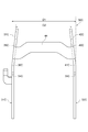
- FIG. 11 is a diagram showing a mounted portion according to another embodiment.
- FIG. 12 is a perspective view of the mounted portion shown in FIG. 11 as viewed from
- the combination weighing device 1 includes a charging chute 2, a distributed feeder 3, a plurality of radiating feeders 4, a plurality of pool hoppers 5, a plurality of weighing hoppers 6, a collecting chute 7, and the like.
- a timing hopper 8 and a measuring unit 9 are provided.
- the combination weighing device 1 weighs the article A (an article having a variation in the mass of a single substance such as agricultural products, marine products, processed foods, etc.) supplied by the conveyor 15 so as to have a target weighing value, and is a bag making and packaging machine. Supply to 16.
- the bag-making and packaging machine 16 forms the film into a bag having a predetermined capacity, and packs the article A that has been weighed and supplied by the combination weighing device 1.
- the charging chute 2 is arranged below the transport end 15a of the conveyor 15.
- the charging chute 2 receives the article A that has been conveyed from the outside by the transfer conveyor 15 and has fallen from the transfer end 15a of the transfer conveyor 15 and discharges it downward.
- the distributed feeder 3 is arranged below the input chute 2.
- the dispersion feeder 3 has a conical transport surface 3a that diverges downward. As the transport surface 3a is vibrated, the dispersion feeder 3 uniformly transports the article A discharged from the charging chute 2 to the top of the transport surface 3a toward the outer edge of the transport surface 3a.
- the plurality of radiating feeders 4 are arranged radially along the outer edge of the transport surface 3a of the dispersion feeder 3.
- Each radiating feeder 4 has a trough 4a extending from below to outside the outer edge of the transport surface 3a.
- Each radiation feeder 4 conveys the article A discharged from the outer edge of the transport surface 3a toward the tip of the trough 4a by vibrating the trough 4a.
- the plurality of pool hoppers 5 are arranged so as to surround, for example, a center line (not shown) parallel to the vertical direction. Each pool hopper 5 is arranged below the tip of the trough 4a of each radiation feeder 4. Each pool hopper 5 temporarily stores the article A discharged from the corresponding radiant feeder 4. Each pool hopper 5 discharges the temporarily stored article A downward.
- the specific configuration of each pool hopper 5 will be described later.
- the plurality of weighing hoppers 6 are arranged so as to surround the center line, for example. Each weighing hopper 6 is arranged below the gate 5a of each pool hopper 5. Each weighing hopper 6 has a gate 6a that can be opened and closed with respect to its bottom. Each weighing hopper 6 temporarily stores the article A discharged from the corresponding pool hopper 5 by closing the gate 6a. Further, each weighing hopper 6 discharges the temporarily stored article A downward by opening the gate 6a.
- the collecting chute 7 collects the articles A discharged from each weighing hopper 6.
- the collective chute 7 has an upper chute portion 7a and a lower chute portion 7b.
- the upper chute portion 7a receives the article A discharged from each measuring hopper 6 and slides the article A toward the lower chute portion 7b.
- the lower chute portion 7b is a truncated cone-shaped cylinder that tapers downward.
- the lower chute portion 7b discharges the article A to the timing hopper 8.
- the timing hopper 8 is arranged below the collective chute 7.
- the timing hopper 8 has a gate 8a that can be opened and closed with respect to the bottom thereof. By closing the gate 8a, the timing hopper 8 temporarily stores the article A discharged from the collecting chute 7. Further, the timing hopper 8 opens the gate 8a to discharge the temporarily stored article A to the bag making / packaging machine 16.
- the input chute 2, the dispersion feeder 3, the plurality of radiation feeders 4, the plurality of pool hoppers 5, and the plurality of measuring hoppers 6 are directly or indirectly supported by the support 11.
- the support 11 has a cylindrical shape.
- the collective chute 7 and the timing hopper 8 are directly or indirectly supported by the frame 10.
- the measuring unit 9 is housed in the support 11 supported by the frame 10.
- the measuring unit 9 has a plurality of load cells 9a.
- Each load cell 9a supports a corresponding weighing hopper 6.
- the measuring unit 9 measures a weighing value according to the mass of the article A.
- the control unit 12 is arranged in the support 11.
- the control unit 12 has a CPU (Central Processing Unit), a ROM (Read Only Memory), a RAM (Random Access Memory), and the like.
- the control unit 12 transfers the distributed feeder 3 and the radiating feeder 4, opens and closes the gate 21 of each pool hopper 5, opens and closes the gate 6a of each measuring hopper 6, opens and closes the gate 8a of the timing hopper 8, and the like. Controls the operation of each part of the combination weighing device 1.
- the control unit 12 stores the measured value measured by the measuring unit 9 and the measuring hopper 6 for storing the article A corresponding to the measured value in association with each other.
- the control unit 12 selects a combination of measurement values from a plurality of measurement values measured by the measurement unit 9 and associated with each measurement hopper 6 so that the total value becomes the target measurement value. More specifically, the control unit 12 selects a combination of measurement values from a plurality of measurement values output by the measurement unit 9 so that the total value falls within a predetermined range with the target measurement value as the lower limit value. Then, the control unit 12 causes the measuring hopper 6 corresponding to the combination to discharge the article A.
- the pool hopper 5 has a main body portion 20, a gate 21, a link mechanism 22, and a mounting portion 23.
- terms such as “upper” and “lower” are used for the pool hopper 5 attached to the combination weighing device 1.
- the vertical direction corresponds to the height direction of the support 11 (combination measuring device 1).
- the main body 20 stores the article A.
- the main body 20 is a tubular body.
- the main body 20 has an opening 20a to which the article A is supplied and an opening (not shown) for discharging the article A.
- the lower side surface of the main body 20 has a shape that tapers downward.
- the gate 21 has a first gate 21a and a second gate 21b (see FIG. 4). Each of the first gate 21a and the second gate 21b can be opened and closed with respect to the opening on the lower side of the main body portion 20.
- the link mechanism 22 opens and closes the first gate 21a and the second gate 21B with respect to the opening on the lower side of the main body 20.
- the link mechanism 53 includes a first movable portion 22a, a second movable portion 22b, and an operating portion 22c. In the link mechanism 53, when the operation unit 22c is operated by the drive unit 14 (see FIG. 4), the first movable portion 22a and the second movable portion 22b are movable, and the first gate 21a and the second gate 21b are opened and closed. Let me.
- the mounting portion 23 has a structure that can be attached to and detached from the mounted portion 30 (see FIG. 3) provided on the support 11.
- the mounting portion 23 includes a first mounting member 23a and a second mounting member 23b.
- the first mounting member 23a and the second mounting member 23b are mounted on the side surface of the main body portion 20.
- Each of the first mounting member 23a and the second mounting member 23b extends along the vertical direction.
- the first mounting member 23a and the second mounting member 23b are arranged at predetermined intervals in the width direction of the main body portion 20.
- the mounting portion 23 has a first locking member (first member) 24 and a second locking member (second member) 25.
- Each of the first locking member 24 and the second locking member 25 exhibits, for example, a columnar shape.
- the first locking member 24 and the second locking member 25 are arranged (hanging) between the first mounting member 23a and the second mounting member 23b over the first mounting member 23a and the second mounting member 23b. ).
- the first locking member 24 and the second locking member 25 extend along the width direction of the main body 20.
- the first locking member 24 and the second locking member 25 are arranged at predetermined intervals in the vertical direction (moving direction of the article A) of the main body portion 20.
- the second locking member 25 is arranged above the first locking member 24 in the vertical direction of the main body portion 20.
- the first locking member 24 is arranged below the second locking member 25 in the vertical direction of the main body portion 20.
- the support 11 has a plurality of attached portions 30.
- a plurality of mounted portions 30 are arranged at predetermined intervals in the circumferential direction of the support 11.
- Each attached portion 30 is fixed to the support 11 via the fixing portion 13.
- the attached portion 30 has a first support member 31, a second support member 32, and a fixing member 33.
- the first support member 31, the second support member 32, and the fixing member 33 are integrally formed.
- the fixing member 33 is fixed to the fixing portion 13. As a result, the attached portion 30 is supported by the support 11.
- the first support member 31 and the second support member 32 extend along the vertical direction.
- the first support member 31 and the second support member 32 are arranged so as to face each other in the width direction of the pool hopper 5.
- the first support member 31 has a first regulation portion 34, a second regulation portion 35, a support portion 36, a guide portion 37, and an inclined portion 38.
- the second support member 32 includes a first regulation portion 39, a second regulation portion 40, a support portion 41, a guide portion 42 (first inclined surface 42a, second inclined surface 42b, and recess 42c), and an inclined portion 43. And have.
- the first support member 31 and the second support member 32 have the same configuration. Therefore, the configuration of the first support member 31 will be described in detail below.
- the first regulation unit 34 defines the position of the first locking member 24 of the pool hopper 5 at the attachment position (position shown in FIG. 4) where the pool hopper 5 is attached to the support 11.
- the first defining portion 34 is the first when the pool hopper 5 is swung toward the support 11 side around the second locking member 25 in a state where the second locking member 25 is held by the second defining portion 35. 1 It is arranged on the orbit of the locking member 24.
- the first regulation portion 34 is composed of recesses formed by intersecting two surfaces when viewed from the opposite direction of the first support member 31 and the second support member 32.
- the second regulation unit 35 defines the position of the second locking member 25 of the pool hopper 5 at the attachment position (position shown in FIG. 4) where the pool hopper 5 is attached to the support 11.
- the second regulation portion 35 has a concave shape when viewed from the opposite direction of the first support member 31 and the second support member 32.
- the second regulation unit 35 is composed of a first regulation unit 35a, a second regulation unit 35b, and a mounting unit 35c.
- the first regulating portion 35a is arranged below the guide portion 37, and is composed of a surface extending along the vertical direction.
- the second regulating portion 35b is arranged outside the support 11 in the radial direction with respect to the first regulating portion 35a, and extends along the vertical direction.
- the mounting portion 35c is located between the first regulating portion 35a and the second regulating portion 35b, and is composed of a surface extending along the horizontal direction.
- the second regulation unit 35 is orthogonal to the radial direction of the support 11 in the second locking member 25 (the extending direction and the vertical direction of the second locking member 25) by the first regulation unit 35a and the second regulation unit 35b. Regulate movement in the direction).
- the second defining portion 35 rotatably holds the second locking member 25.
- the support portion 36 is arranged between the first regulation portion 34 and the second regulation portion 35 in the vertical direction.
- the support portion 36 can support the first locking member 24.
- the support portion 36 projects toward the pool hopper 5 side from the front surface of the first support member 31.
- the support portion 36 supports the first locking member 24 on its upper surface.
- the guide portion 37 is a second locking member when the pool hopper 5 is swung toward the support 11 side around the first locking member 24 in a state where the first locking member 24 is supported by the support portion 36. It is arranged in 25 orbits.
- the guide portion 37 guides the second locking member 25 so that the second locking member 25 moves downward in the vertical direction from the position on the track and is located at the second defining portion 35.
- the guide portion 37 has a first inclined surface 37a, a second inclined surface 37b, and a recess 37c.
- the first inclined surface 37a functions as a guide surface for guiding the second locking member 25.
- the first inclined surface 37a is inclined downward with respect to the horizontal direction.
- the first inclined surface 37a inclines downward with a direction away from the support 11 in the horizontal direction (diameter direction of the support 11).
- the upper end of the first inclined surface 37a is located on the track of the second locking member 25.
- the second inclined surface 37b is continuous with the upper end portion of the first inclined surface 37a.
- the second inclined surface 37b is inclined upward with respect to the horizontal direction.
- the second inclined surface 37b is inclined upward with a direction away from the support 11 in the horizontal direction.
- the lower end of the second inclined surface 37b is located on the track of the second locking member 25.
- the second inclined surface 37b is inclined so that the second inclined surface 37b and the first inclined surface 37a form an angle of 180 ° or less.
- the recess 37c is provided at the upper end of the first inclined surface 37a (the lower end of the second inclined surface 37b), and is arranged at a position on the track of the second locking member 25.
- the recess 37c is formed by the first inclined surface 37a and the second inclined surface 37b.
- the recess 37c has a triangular shape when viewed from the direction in which the first support member 31 and the second support member 32 face each other.
- the distance between the support portion 36 and the recess 37c is equivalent to the distance between the first locking member 24 and the second locking member 25 of the pool hopper 5.
- the inclined portion 38 is arranged at a position below the track of the second locking member 25 in the vertical direction and away from the support 11 in the horizontal direction with respect to the guide portion 37.
- the inclined portion 38 is arranged at the upper end portion of the second regulation portion 35b of the second regulation portion 35.
- the inclined portion 38 can guide the second locking member 25 with respect to the second defining portion 35, and is inclined upward with respect to the horizontal direction.
- the inclined portion 38 is inclined toward a direction away from the support 11 in the horizontal direction.
- the mounting portion 23 of the pool hopper 5 is mounted on the mounted portion 30.
- the first locking member 24 is located at the first defined portion 34, 39 of the attached portion 30, and the second locking member 25 is the second specified portion of the attached portion 30. It is located at 35 and 40 and is supported by the attached portion 30.
- the force of the first locking member 24 to move toward the pool hopper 5 and the force of the second locking member 25 to move toward the support 11 act due to the weight of the main body 20. ..
- the movement of the first locking member 24 is regulated by the first regulating portions 34 and 39, and the movement of the second locking member 25 is regulated by the second regulating portions 35 and 40. Therefore, the pool hopper 5 is held by the attached portion 30.
- the position of the support portion 36 (41) is confirmed so that the first locking member 24 of the pool hopper 5 is hooked on the support portion 36 (41) of the attached portion 30, and the pool hopper 5 Is tilted to move the first locking member 24 toward the support portion 36 (41).
- the pool hopper 5 is temporarily positioned with respect to the attached portion 30.
- the pool hopper 5 is swung toward the support 11 side with the first locking member 24 of the pool hopper 5 as a fulcrum.
- the pool hopper 5 rotates toward the support 11 side with the first locking member 24 as a fulcrum.
- the second locking member 25 moves in an arcuate trajectory, and the second locking member 25 moves into the recess 37c (42c) of the guide portion 37 (42) of the attached portion 30.
- the pool hopper 5 With the second locking member 25 in contact with the recess 37c (42c), the pool hopper 5 is further pushed toward the support 11 side, and the pool hopper 5 is set with the second locking member 25 of the pool hopper 5 as a fulcrum. Swing toward the support 11 side. As a result, the pool hopper 5 rotates toward the support 11 side with the second locking member 25 as a fulcrum. Then, the first locking member 24 moves in a direction away from the support portion 36 (41), and the support by the support portion 36 (41) is released.
- the pool hopper 5 can move in the vertical direction with respect to the attached portion 30. Become.
- the second locking member 25 is slid along the first inclined surface 37a (42a) of the guide portion 37 (42), the second locking member 25 is moved by the guide portion 37 (42) to the second defined portion 35. Guided by (40), it is located in the second regulation part 35 (40).
- the first locking member 24 moves downward with the movement of the second locking member 25.
- the first locking member 24 is located at the first defining portion 34 (39) located below the supporting portion 36 (41).
- the first locking member 24 is located in the first defining portion 34 (39) and the second locking member 25 is located in the second defining portion 35 (40), and the pool The hopper 5 is attached to the attached portion 30 (support 11).
- the mounting portion 23 of the pool hopper 5 has a first locking member 24 and a second locking member 25.
- the second locking member 25 is arranged on the main body 20 on the upstream side in the moving direction of the article A with respect to the first locking member 24. That is, in the pool hopper 5, the first locking member 24 is arranged on the lower side, and the second locking member 25 is arranged on the upper side.
- the first locking member 24 is brought closer to the support portions 36, 41 while checking (visually) the support portions 36, 41.
- the support portions 36 and 41 support the first locking member 24.
- the pool hopper 5 can be temporarily positioned with respect to the support 11.
- the pool hopper 5 In a state where the first locking member 24 is supported by the support portions 36 and 41, the pool hopper 5 is swung toward the support 11 side around the first locking member 24. As a result, the second locking member 25 moves to the guide portions 37 and 42.
- the pool hopper 5 can be swung toward the support 11 side around the second locking member 25, and the pool hopper 5 is further moved.
- the support of the first locking member 24 in the support portions 36 and 41 is released.
- the pool hopper 5 can be moved in the vertical direction. Therefore, by moving the second locking member 25 along the guide portions 37 and 42, the second locking member 25 is moved to the second defining portion 35, Located at 40.
- the first locking member 24 is located in the first regulation portions 34 and 39 arranged below the support portions 36 and 41.
- the pool hopper 5 is attached to the support 11. be able to.
- the pool hopper 5 can be attached to the support 11 while maintaining the positional relationship between the attachment portion 23 of the pool hopper 5 and the attached portion 30 of the support 11. Therefore, in the combination weighing device 1, the workability of attaching the pool hopper 5 can be improved.
- the guide portions 37, 42 have first inclined surfaces 37a, 42a that incline downward with respect to the horizontal direction.
- the first inclined surfaces 37a and 42a are inclined toward a direction away from the support 11 in the horizontal direction.
- the guide portions 37, 42 are provided at the upper ends of the first inclined surfaces 37a, 42a, and the recesses 37c, which are arranged at positions on the track of the second locking member 25, It has 42c.
- the distance between the support portions 36, 41 and the recesses 37c, 42c is equivalent to the distance between the first locking member 24 and the second locking member 25 of the pool hopper 5.
- the pool hopper 5 is swung toward the support 11 side around the second locking member 25 in the recesses 37c and 42c, so that the support of the first locking member 24 in the support portions 36 and 41 is more reliable. Can be released.
- the attached portion 30 is separated from the support 11 in the vertical direction below the track of the second locking member 25 and in the horizontal direction from the guide portion 37.
- the second locking member 25 can be guided with respect to the second defining portions 35, 40, and has inclined portions 38, 43 inclined upward with respect to the horizontal direction.
- the inclined portions 38 and 43 are inclined toward a direction away from the support 11 in the horizontal direction.
- the guide portions 37, 42 and the inclined portions 38, 43 can guide the second locking member 25 with respect to the second defining portions 35, 40. Therefore, the second locking member 25 can be reliably positioned in the second regulation portions 35 and 40.
- the inclined portions 38 and 43 are inclined upward in the direction away from the support 11 in the horizontal direction. Therefore, the entrance of the second locking member 25 to the second regulation portions 35 and 40 becomes wider. As a result, the second locking member 25 can be more reliably positioned at the second regulation portions 35 and 40.
- the guide portions 37, 42 have the first inclined surfaces 37a, 42a, the second inclined surfaces 37b, 42b, and the recesses 37c, 42c has been described as an example.
- the guide portion does not have to have the first inclined surfaces 37a and 42a, the second inclined surfaces 37b and 42b, and the recesses 37c and 42c.
- the guide portion may have at least a surface (for example, a surface extending along the vertical direction) for guiding the second locking member 25 to the second defining portions 35 and 40.
- the embodiment in which the attached portion 30 has the inclined portions 38 and 43 has been described as an example.
- the first support member 31A of the attached portion 30A does not have to include the inclined portions 38 and 43.
- the second support member does not have to include the inclined portions 38 and 43.
- the measuring hopper 6 may have the same configuration as the pool hopper 5. Further, as an example, a mode including a pool hopper 5 and a weighing hopper 6 as hoppers has been described. However, a booster hopper to which the article A is supplied from the weighing hopper 6 may be further provided.
- the embodiment in which the dispersion feeder 3 conveys the article A by vibration has been described as an example.
- the transport surface 3a may rotate to transport the article A.
- the radiation feeder 4 may be in the form of transporting the article A by a coil unit (screw) that can be driven to rotate or a belt conveyor.
- the control unit 12 controls the rotation speed (rpm) of the coil unit or the like as a conveying force.
- the control unit 12 controls the rotation speed of the rollers for driving the belt and the like.
- the present invention includes a hopper for temporarily retaining the article and discharging the article, and a support for detachably supporting the hopper, and the hopper retains the article. It has a main body portion and a mounting portion for attaching the main body portion to the support, and the mounting portion includes a first member extending along the width direction of the main body portion and the first member. Also has a second member which is arranged on the upstream side of the main body in the moving direction of the article and extends along the width direction, and the support is attached to the attachment portion of the hopper.
- the mounted portion has a mounted portion, and the mounted portion defines the positions of the first defining portion and the second member that define the position of the first member at the mounting position where the hopper is mounted on the support.
- the first defining portion is the first when the hopper is swung toward the support with the second member as a center in a state where the second member is held by the second defining portion. It is a combination weighing device arranged on the track of a member.
- the mounting portion of the hopper has a first member and a second member.
- the second member is arranged on the main body portion upstream of the first member in the moving direction of the article. That is, in the hopper, the first member is arranged on the lower side and the second member is arranged on the upper side.
- the second member is positioned in the second regulation part. In this state, the hopper can swing around the second support portion. Then, the first member of the hopper swings in the direction approaching the support, that is, the hopper swings toward the support.
- the second member is held by the second specified portion, the hopper swings due to the weight of the main body portion without the operator exerting any force.
- the first defined portion is arranged on the track of the first member. Therefore, as the hopper swings, the first member is located at the first defined portion.
- the hopper can be attached to the support.
- the combination weighing device does not require the work of hooking the four hooks at the same time as in the conventional case.
- the hopper can be attached to the support by the work of locating the second member in the second specified portion. Therefore, in the combination weighing device, the workability of attaching the hopper can be improved.
- the attached portion 30B has a first support member 31B.
- the first support member 31B has a first regulation portion 34, a second regulation portion 35, a guide portion 37, and an inclined portion 38.
- a second support member having the same configuration as the first support member 31B is arranged at a position facing the first support member 31B.
- the first support member 31B is different from the first support member 31 in that it does not have the support portion 36 of the first support member 31.
- the method of attaching the pool hopper 5 to the support 11 (attachment method) will be described. First, the second locking member 25 is moved toward the second defining portion 35 so that the second locking member 25 of the pool hopper 5 is caught by the second defining portion 35 of the attached portion 30.
- the pool hopper 5 is swung toward the support 11 side with the second locking member 25 of the pool hopper 5 as a fulcrum.
- the pool hopper 5 rotates toward the support 11 side with the second locking member 25 as a fulcrum.
- the first locking member 24 moves in an arc-shaped trajectory, and the first locking member 24 comes into contact with the first defined portion 34 of the attached portion 30.
- the first locking member 24 is located at the first defining portion 34.
- the first locking member 24 is located in the first defining portion 34
- the second locking member 25 is located in the second defining portion 35
- the pool hopper 5 is attached. It is attached to 30 (support 11).
- the inclined portion 38 may not be provided.
- first support member 31 and the second support member 32 extend linearly along the vertical direction
- configurations of the first support member and the second support portion are not limited to this.
- the attached portion 30C has a first support member 31C, a second support member 32C, and a connecting portion 44.
- the first support member 31C, the second support member 32C, and the connecting portion 44 are integrally formed.
- the attached portion 30C is used for the support 11 that supports the measuring hopper 6.
- the first support member 31C and the second support member 32C extend in the vertical direction.
- the first support member 31C and the second support member 32C are arranged so as to face each other in the width direction of the measuring hopper 6.
- the first support member 31C has a first regulation portion 34C, a second regulation portion 35C, a support portion 36C, and a guide portion 37C.
- the second support member 32C has a first regulation portion 39C, a second regulation portion 40C, a support portion 41C, and a guide portion 42C.
- the distance between the first support member 31C and the second support member 32C in the width direction becomes shorter from the support portions 36C and 41C toward the upper side.
- the distance D1 between the first support member 31C and the second support member 32C at the positions of the support portions 36C and 41C is the same as that of the first support member 31C at the upper positions of the first support member 31C and the second support member 32C.
- the distance to the second support member 32C is longer than the distance D2 (D1> D2).
- the distance between the first support member 31C and the second support member 32C is the distance between the outer surfaces of the first support member 31C and the second support member 32C in the width direction.
- the first support member 31C is bent at the position of the support portion 36C when viewed from the radial direction of the support body 11, and is inclined inward in the width direction starting from the position of the support portion 36C.
- the second support member 32C is bent at the position of the support portion 41C when viewed from the radial direction of the support body 11, and is inclined inward in the width direction starting from the position of the support portion 41C.
- the connecting portion 44 connects the first support member 31C and the second support member 32C.
- the connecting portion 44 extends along the width direction of the measuring hopper 6.
- the connecting portion 44 has a convex shape when viewed from the radial direction of the support 11.
- the connecting portion 44 functions as a regulating portion that regulates the movement of the second locking member 25.
- the connecting portion 44 restricts the movement of the support 11 in the second locking member 25 in the radial direction (the extending direction of the second locking member 25 and the direction orthogonal to the vertical direction).
- the attached portion 30C has a first support member 31C and a second support member 32C which are arranged to face each other in the width direction of the measuring hopper 6 and extend in the height direction of the support 11. ..
- the distance between the first support member 31C and the second support member 32C in the width direction becomes shorter from the support portions 36C and 41C toward the upper side.
- the mounted portion 30C may be looked down, and the support portions 36C and 41C may be difficult to see from the operator. In this case, it may not be easy to support the first locking member 24 by the support portions 36C and 41C.
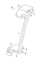
- the distance between the first support member 31C provided with the support portions 36C and 41C and the second support member 32C in the width direction becomes shorter from the support portions 36C and 41C toward the upper side. That is, the width of the mounted portion 30C is narrower than that of the support portions 36C and 41C. As a result, as shown in FIG.
- the first locking member 24 can be brought closer to the support portions 36C and 41C while checking the support portions 36C and 41C, and the support portions 36C and 41C can support the first locking member 24. ..
- the mounting workability of the weighing hopper 6 can be improved.
Landscapes
- Physics & Mathematics (AREA)
- General Physics & Mathematics (AREA)
- Engineering & Computer Science (AREA)
- Mechanical Engineering (AREA)
- Filling Or Emptying Of Bunkers, Hoppers, And Tanks (AREA)
Abstract
L'invention concerne un dispositif de pesée par combinaison 1 pourvu d'une trémie de stockage 5 et d'un corps de support 11. Une partie fixée 30 du corps de support 11 comprend : des premières parties de définition 34, 39 qui définissent la position d'un premier élément de verrouillage 24 et des secondes parties de définition 35, 40 qui définissent la position d'un second élément de verrouillage 25, dans une position de fixation dans laquelle la trémie de stockage est fixée au corps de support 11 ; des parties de support 36, 41 pouvant supporter le premier élément de verrouillage 24 ; et des parties de guidage 37, 42 qui sont disposés sur la trajectoire du second élément de verrouillage 25 lorsque la trémie de stockage 5 est basculée vers le côté corps de support 11 autour du premier élément de verrouillage 24, dans un état où le premier élément de verrouillage 24 est supporté par les parties de support 36, 41, et qui guident le second élément de verrouillage 25 de telle sorte que le second élément de verrouillage 25 se déplace en dessous de ladite position sur la trajectoire, dans le sens de la hauteur, et se positionne sur les secondes parties de définition 35, 40.
Priority Applications (5)
| Application Number | Priority Date | Filing Date | Title |
|---|---|---|---|
| JP2020544547A JP6777357B1 (ja) | 2019-03-13 | 2020-03-11 | 組合せ計量装置 |
| EP20767454.0A EP3767254B1 (fr) | 2019-03-13 | 2020-03-11 | Dispositif de pesée par combinaison |
| DK20767454.0T DK3767254T3 (da) | 2019-03-13 | 2020-03-11 | Kombinationsvejeindretning |
| US16/975,336 US11333546B2 (en) | 2019-03-13 | 2020-03-11 | Combination weighing apparatus with improved hopper attachment workability |
| CN202080003024.6A CN112204361B (zh) | 2019-03-13 | 2020-03-11 | 组合计量装置 |
Applications Claiming Priority (2)
| Application Number | Priority Date | Filing Date | Title |
|---|---|---|---|
| JP2019046126 | 2019-03-13 | ||
| JP2019-046126 | 2019-03-13 |
Publications (1)
| Publication Number | Publication Date |
|---|---|
| WO2020184632A1 true WO2020184632A1 (fr) | 2020-09-17 |
Family
ID=72427928
Family Applications (1)
| Application Number | Title | Priority Date | Filing Date |
|---|---|---|---|
| PCT/JP2020/010641 Ceased WO2020184632A1 (fr) | 2019-03-13 | 2020-03-11 | Dispositif de pesée par combinaison |
Country Status (6)
| Country | Link |
|---|---|
| US (1) | US11333546B2 (fr) |
| EP (1) | EP3767254B1 (fr) |
| JP (1) | JP6777357B1 (fr) |
| CN (1) | CN112204361B (fr) |
| DK (1) | DK3767254T3 (fr) |
| WO (1) | WO2020184632A1 (fr) |
Cited By (1)
| Publication number | Priority date | Publication date | Assignee | Title |
|---|---|---|---|---|
| JPWO2022085597A1 (fr) * | 2020-10-19 | 2022-04-28 |
Families Citing this family (4)
| Publication number | Priority date | Publication date | Assignee | Title |
|---|---|---|---|---|
| WO2020003410A1 (fr) * | 2018-06-27 | 2020-01-02 | 大和製衡株式会社 | Dispositif de pesage combiné |
| WO2022044155A1 (fr) * | 2020-08-26 | 2022-03-03 | 大和製衡株式会社 | Dispositif d'alimentation de transport d'articles et balance combinée le comprenant |
| WO2022260620A1 (fr) * | 2021-06-08 | 2022-12-15 | Balsu Gida Sanayi Ve Ticaret Anonim Sirketi | Unité de pesage utilisée pour déterminer la productivité de noisettes dans des installations de transformation de noisettes |
| IT202200008882A1 (it) * | 2022-05-03 | 2023-11-03 | Ilapak Italia S P A | Kit di componenti per comporre una tramoggia intercambiabile per la dosatura/pesatura di prodotti in una apparecchiatura di pesatura combinata. |
Citations (6)
| Publication number | Priority date | Publication date | Assignee | Title |
|---|---|---|---|---|
| JPS62249018A (ja) * | 1986-04-21 | 1987-10-30 | Anritsu Corp | 組合せ計量装置 |
| JPH09264776A (ja) * | 1996-03-27 | 1997-10-07 | Ishida Co Ltd | 計量装置 |
| US5736683A (en) * | 1996-03-15 | 1998-04-07 | Kliklok Corporation | Multiple hopper weighing and transfer system |
| JP2012237643A (ja) * | 2011-05-11 | 2012-12-06 | Ishida Co Ltd | 組合せ計量機のホッパアセンブリ |
| JP2016132568A (ja) | 2015-01-22 | 2016-07-25 | 株式会社イシダ | ホッパ並びにそれを搭載した組合せ計量装置 |
| JP2018048851A (ja) * | 2016-09-20 | 2018-03-29 | 株式会社イシダ | ホッパ及び組合せ計量装置 |
Family Cites Families (11)
| Publication number | Priority date | Publication date | Assignee | Title |
|---|---|---|---|---|
| GB8705451D0 (en) * | 1987-03-09 | 1987-04-15 | Driver Southall | Combinational weighing systems |
| US5379923A (en) * | 1992-06-17 | 1995-01-10 | Eagle Packaging Corp. | Hopper for a weighing machine |
| US5611437A (en) * | 1995-04-19 | 1997-03-18 | Sea-Chang Ting | Automatically openable and closable hopper set for a fruit weighing and sorting machine |
| JP3670295B2 (ja) * | 1996-07-03 | 2005-07-13 | 株式会社イシダ | ホッパの着脱性を改善した計量装置 |
| DK3196610T3 (da) * | 2014-09-19 | 2020-08-31 | Ishida Seisakusho | Kombinationsmåleindretning |
| WO2016125407A1 (fr) * | 2015-02-04 | 2016-08-11 | 株式会社イシダ | Dispositif de pesage combiné |
| CN205221687U (zh) * | 2015-12-14 | 2016-05-11 | 宁夏合力万兴汽车制造有限公司 | 挂桶垃圾车垃圾桶固定装置 |
| CN205441615U (zh) * | 2015-12-16 | 2016-08-10 | 宁夏合力万兴汽车制造有限公司 | 挂桶垃圾车提升机 |
| EP3428587B1 (fr) * | 2016-03-07 | 2024-06-26 | Ishida Co., Ltd. | Dispositif de pesage combiné |
| CN105598107B (zh) * | 2016-03-16 | 2017-10-31 | 湖北合加环境设备有限公司 | 一种垃圾桶清洗专用车 |
| JP6654480B2 (ja) * | 2016-03-18 | 2020-02-26 | 株式会社イシダ | 組合せ計量装置 |
-
2020
- 2020-03-11 JP JP2020544547A patent/JP6777357B1/ja active Active
- 2020-03-11 US US16/975,336 patent/US11333546B2/en active Active
- 2020-03-11 DK DK20767454.0T patent/DK3767254T3/da active
- 2020-03-11 WO PCT/JP2020/010641 patent/WO2020184632A1/fr not_active Ceased
- 2020-03-11 CN CN202080003024.6A patent/CN112204361B/zh active Active
- 2020-03-11 EP EP20767454.0A patent/EP3767254B1/fr active Active
Patent Citations (6)
| Publication number | Priority date | Publication date | Assignee | Title |
|---|---|---|---|---|
| JPS62249018A (ja) * | 1986-04-21 | 1987-10-30 | Anritsu Corp | 組合せ計量装置 |
| US5736683A (en) * | 1996-03-15 | 1998-04-07 | Kliklok Corporation | Multiple hopper weighing and transfer system |
| JPH09264776A (ja) * | 1996-03-27 | 1997-10-07 | Ishida Co Ltd | 計量装置 |
| JP2012237643A (ja) * | 2011-05-11 | 2012-12-06 | Ishida Co Ltd | 組合せ計量機のホッパアセンブリ |
| JP2016132568A (ja) | 2015-01-22 | 2016-07-25 | 株式会社イシダ | ホッパ並びにそれを搭載した組合せ計量装置 |
| JP2018048851A (ja) * | 2016-09-20 | 2018-03-29 | 株式会社イシダ | ホッパ及び組合せ計量装置 |
Cited By (6)
| Publication number | Priority date | Publication date | Assignee | Title |
|---|---|---|---|---|
| JPWO2022085597A1 (fr) * | 2020-10-19 | 2022-04-28 | ||
| WO2022085597A1 (fr) * | 2020-10-19 | 2022-04-28 | 株式会社ツカサ | Dispositif de distribution de matière particulaire |
| KR20220157473A (ko) * | 2020-10-19 | 2022-11-29 | 츠카사 컴퍼니 리미티드 | 분립체 공급장치 |
| JP7387210B2 (ja) | 2020-10-19 | 2023-11-28 | 株式会社ツカサ | 粉粒体供給装置 |
| US12145812B2 (en) | 2020-10-19 | 2024-11-19 | Tsukasa Co., Ltd. | Particulate material supply apparatus |
| KR102807498B1 (ko) | 2020-10-19 | 2025-05-13 | 츠카사 컴퍼니 리미티드 | 분립체 공급장치 |
Also Published As
| Publication number | Publication date |
|---|---|
| EP3767254A4 (fr) | 2021-12-08 |
| CN112204361A (zh) | 2021-01-08 |
| JPWO2020184632A1 (ja) | 2021-03-18 |
| US20210215529A1 (en) | 2021-07-15 |
| EP3767254A1 (fr) | 2021-01-20 |
| CN112204361B (zh) | 2023-07-14 |
| US11333546B2 (en) | 2022-05-17 |
| DK3767254T3 (da) | 2023-10-02 |
| EP3767254B1 (fr) | 2023-09-20 |
| JP6777357B1 (ja) | 2020-10-28 |
Similar Documents
| Publication | Publication Date | Title |
|---|---|---|
| JP6777357B1 (ja) | 組合せ計量装置 | |
| US7790990B2 (en) | Combination weigher with peripheral annular recycling table | |
| AU2006320066B2 (en) | Metering apparatus | |
| EP3892572A1 (fr) | Dispositif d'alimentation à avance directe et dispositif de pondération par combinaison pourvu dudit système | |
| US4516644A (en) | Apparatus for regulating flow of articles in computer scale | |
| US10782180B2 (en) | Hopper and combination weighing device | |
| EP1164365B1 (fr) | Dispositif de comptage et de pesage par lots | |
| JP6654480B2 (ja) | 組合せ計量装置 | |
| EP2450678B1 (fr) | Goulotte de distribution de produit pour balance (échelles) | |
| JP2017015600A (ja) | ホッパ及びこれを備えた組合せ秤 | |
| US5942732A (en) | Automatic weigh and count filling machine feed mechanism | |
| US6271485B1 (en) | Article alignment device | |
| JPH08271327A (ja) | 棒状組合せ計量機 | |
| JP6982923B2 (ja) | 物品滞留装置及び支持体 | |
| US7025194B2 (en) | Article moving apparatus and direction changing apparatus for sticks | |
| JP7429944B2 (ja) | タイミングホッパおよび組合せ計量装置 | |
| JP6157922B2 (ja) | 組合せ秤の物品搬送構造 | |
| JPH08145769A (ja) | 組合せ計量装置の被計量物分散供給装置 | |
| JP7669100B2 (ja) | 分散トレイ及びこれを備えた組合せ秤 | |
| JP4611727B2 (ja) | 組合せ計量装置 | |
| JP7551245B2 (ja) | 投入装置及びこれを備えた計量装置 | |
| JP2018155636A (ja) | 分散装置及び組合せ計量装置 | |
| JP2020153776A (ja) | 組合せ計量装置 | |
| JP2019035601A (ja) | トラフ、供給フィーダ及び計量装置 | |
| JP2021004761A (ja) | 計量装置及び組合せ計量装置 |
Legal Events
| Date | Code | Title | Description |
|---|---|---|---|
| ENP | Entry into the national phase |
Ref document number: 2020544547 Country of ref document: JP Kind code of ref document: A |
|
| ENP | Entry into the national phase |
Ref document number: 2020767454 Country of ref document: EP Effective date: 20201014 |
|
| 121 | Ep: the epo has been informed by wipo that ep was designated in this application |
Ref document number: 20767454 Country of ref document: EP Kind code of ref document: A1 |
|
| NENP | Non-entry into the national phase |
Ref country code: DE |