WO2020194496A1 - Procédé de production et dispositif de production de pièce décorative tridimensionnelle en forme de bande composée de résine synthétique thermoplastique - Google Patents
Procédé de production et dispositif de production de pièce décorative tridimensionnelle en forme de bande composée de résine synthétique thermoplastique Download PDFInfo
- Publication number
- WO2020194496A1 WO2020194496A1 PCT/JP2019/012791 JP2019012791W WO2020194496A1 WO 2020194496 A1 WO2020194496 A1 WO 2020194496A1 JP 2019012791 W JP2019012791 W JP 2019012791W WO 2020194496 A1 WO2020194496 A1 WO 2020194496A1
- Authority
- WO
- WIPO (PCT)
- Prior art keywords
- shaped
- strip
- decorative piece
- synthetic resin
- mold
- Prior art date
- Legal status (The legal status is an assumption and is not a legal conclusion. Google has not performed a legal analysis and makes no representation as to the accuracy of the status listed.)
- Ceased
Links
Images





Classifications
-
- B—PERFORMING OPERATIONS; TRANSPORTING
- B44—DECORATIVE ARTS
- B44B—MACHINES, APPARATUS OR TOOLS FOR ARTISTIC WORK, e.g. FOR SCULPTURING, GUILLOCHING, CARVING, BRANDING, INLAYING
- B44B5/00—Machines or apparatus for embossing decorations or marks, e.g. embossing coins
- B44B5/008—Machines or apparatus for embossing decorations or marks, e.g. embossing coins in layered material; connecting a plurality of layers by embossing
-
- B—PERFORMING OPERATIONS; TRANSPORTING
- B32—LAYERED PRODUCTS
- B32B—LAYERED PRODUCTS, i.e. PRODUCTS BUILT-UP OF STRATA OF FLAT OR NON-FLAT, e.g. CELLULAR OR HONEYCOMB, FORM
- B32B37/00—Methods or apparatus for laminating, e.g. by curing or by ultrasonic bonding
- B32B37/0046—Methods or apparatus for laminating, e.g. by curing or by ultrasonic bonding characterised by constructional aspects of the apparatus
- B32B37/0053—Constructional details of laminating machines comprising rollers; Constructional features of the rollers
-
- B—PERFORMING OPERATIONS; TRANSPORTING
- B32—LAYERED PRODUCTS
- B32B—LAYERED PRODUCTS, i.e. PRODUCTS BUILT-UP OF STRATA OF FLAT OR NON-FLAT, e.g. CELLULAR OR HONEYCOMB, FORM
- B32B37/00—Methods or apparatus for laminating, e.g. by curing or by ultrasonic bonding
- B32B37/04—Methods or apparatus for laminating, e.g. by curing or by ultrasonic bonding characterised by the partial melting of at least one layer
-
- B—PERFORMING OPERATIONS; TRANSPORTING
- B44—DECORATIVE ARTS
- B44B—MACHINES, APPARATUS OR TOOLS FOR ARTISTIC WORK, e.g. FOR SCULPTURING, GUILLOCHING, CARVING, BRANDING, INLAYING
- B44B5/00—Machines or apparatus for embossing decorations or marks, e.g. embossing coins
- B44B5/0004—Machines or apparatus for embossing decorations or marks, e.g. embossing coins characterised by the movement of the embossing tool(s), or the movement of the work, during the embossing operation
- B44B5/0009—Rotating embossing tools
-
- B—PERFORMING OPERATIONS; TRANSPORTING
- B44—DECORATIVE ARTS
- B44B—MACHINES, APPARATUS OR TOOLS FOR ARTISTIC WORK, e.g. FOR SCULPTURING, GUILLOCHING, CARVING, BRANDING, INLAYING
- B44B5/00—Machines or apparatus for embossing decorations or marks, e.g. embossing coins
- B44B5/009—Machines or apparatus for embossing decorations or marks, e.g. embossing coins by multi-step processes
-
- B—PERFORMING OPERATIONS; TRANSPORTING
- B44—DECORATIVE ARTS
- B44B—MACHINES, APPARATUS OR TOOLS FOR ARTISTIC WORK, e.g. FOR SCULPTURING, GUILLOCHING, CARVING, BRANDING, INLAYING
- B44B5/00—Machines or apparatus for embossing decorations or marks, e.g. embossing coins
- B44B5/02—Dies; Accessories
- B44B5/028—Heated dies
-
- B—PERFORMING OPERATIONS; TRANSPORTING
- B44—DECORATIVE ARTS
- B44C—PRODUCING DECORATIVE EFFECTS; MOSAICS; TARSIA WORK; PAPERHANGING
- B44C1/00—Processes, not specifically provided for elsewhere, for producing decorative surface effects
- B44C1/24—Pressing or stamping ornamental designs on surfaces
-
- B—PERFORMING OPERATIONS; TRANSPORTING
- B32—LAYERED PRODUCTS
- B32B—LAYERED PRODUCTS, i.e. PRODUCTS BUILT-UP OF STRATA OF FLAT OR NON-FLAT, e.g. CELLULAR OR HONEYCOMB, FORM
- B32B37/00—Methods or apparatus for laminating, e.g. by curing or by ultrasonic bonding
- B32B37/14—Methods or apparatus for laminating, e.g. by curing or by ultrasonic bonding characterised by the properties of the layers
- B32B37/16—Methods or apparatus for laminating, e.g. by curing or by ultrasonic bonding characterised by the properties of the layers with all layers existing as coherent layers before laminating
- B32B37/20—Methods or apparatus for laminating, e.g. by curing or by ultrasonic bonding characterised by the properties of the layers with all layers existing as coherent layers before laminating involving the assembly of continuous webs only
- B32B37/203—One or more of the layers being plastic
-
- B—PERFORMING OPERATIONS; TRANSPORTING
- B44—DECORATIVE ARTS
- B44B—MACHINES, APPARATUS OR TOOLS FOR ARTISTIC WORK, e.g. FOR SCULPTURING, GUILLOCHING, CARVING, BRANDING, INLAYING
- B44B2700/00—Machines, apparatus, tools or accessories for artistic work
Definitions
- the present invention relates to a strip-shaped three-dimensional decorative piece made of thermoplastic synthetic resin such as metal-like, molding-like, and wood-grain to be attached to adherends such as cars, motorcycles, boats, home appliances, game machines, clothing, bags, and hats. It relates to manufacturing methods and manufacturing equipment, and more specifically, striped woven gold wires sewn or attached to uniform sleeves, trousers, hats, etc., and metallic strips attached to cars, home appliances, etc. It relates to a method and an apparatus capable of manufacturing a wood grain band-shaped three-dimensional decorative piece to be attached or sewn to a three-dimensional decorative piece, furniture or the like.
- thermoplastic synthetic resin using high-frequency dielectric heating are manufactured using high-frequency welders, and are used for emblems, appliqués, stickers, etc. (see, for example, Patent Document 1).
- the three-dimensional decorative piece made of a thermoplastic synthetic resin is manufactured by arranging the decorative piece material between the molds and heating the decorative piece material with high frequency dielectric heating to soften, shape and weld the decorative piece material. Therefore, the three-dimensional decorative piece is limited in the width of the mold, particularly the length, and it is not possible to manufacture a long strip-shaped three-dimensional decorative piece.
- An object of the present invention is to provide a method and an apparatus capable of producing a long strip-shaped three-dimensional decorative piece made of a thermoplastic synthetic resin.
- the method for producing a strip-shaped three-dimensional decorative piece made of a thermoplastic synthetic resin of the present invention is A delivery step in which a strip-shaped decorative piece material is sent out by superimposing a strip-shaped thermoplastic synthetic resin film-containing upper layer and a strip-shaped protective / holding layer that is not melted at high frequencies on a strip-shaped thermoplastic synthetic resin sheet-containing lower layer.
- a preheating step of preheating and heating and softening the strip-shaped decorative piece material An upper electrode roll mold that is rotationally driven is arranged on the upper side, a lower electrode mold is arranged below the upper electrode roll mold, and heating and softening is performed between the upper electrode roll mold and the lower electrode roll mold.
- the strip-shaped decorative piece material is fed, and a high frequency is continuously oscillated between the upper electrode roll mold and the lower electrode mold, whereby the strip-shaped decorative piece material is shaped by high-frequency dielectric heating to form a strip.
- the delivery step can be a step of pulling out the lower layer, the upper layer, and the protection / holding layer wound around the delivery roll, respectively, and delivering them in layers.
- the preheating step can be a step in which the strip-shaped decorative piece material is fed between the heated upper heat roll and the lower heat roll, which are arranged so as to face each other in the vertical direction and rotate synchronously, to be heated and softened. ..
- the cooling step can be a step in which the strip-shaped three-dimensional decorative piece is sent between the cooled upper cooling roll and the lower cooling roll, which are arranged so as to face each other in the vertical direction and rotate synchronously, to be cooled.
- the upper electrode roll mold may have a configuration in which one or a plurality of fusing blades are projected on the peripheral surface.
- the upper electrode roll mold can have a structure in which a pattern is engraved on the body portion.
- the synthetic resin foam sheet can be stacked and delivered between the lower layer and the upper layer.
- a base sheet, double-sided tape, or hot melt film can be stacked and delivered under a lower layer containing a strip-shaped thermoplastic synthetic resin sheet.
- the apparatus for manufacturing a strip-shaped three-dimensional decorative piece made of a thermoplastic synthetic resin of the present invention A delivery mechanism that sends out a strip-shaped decorative piece material by superimposing a strip-shaped thermoplastic synthetic resin film-containing upper layer and a strip-shaped protective / holding layer that is not melted at high frequencies on a lower layer containing a strip-shaped thermoplastic synthetic resin sheet.
- a preheating mechanism provided on the downstream side of the delivery mechanism to preheat and heat soften the strip-shaped decorative piece material.
- a shaping mechanism provided on the downstream side of the preheating mechanism, in which an upper electrode roll mold that is rotationally driven is arranged on the upper side, and a lower electrode that comes into contact with the upper electrode roll mold is placed below the upper electrode roll mold.
- a mold is arranged, and the heat-softened strip-shaped decorative piece material is fed between the upper electrode roll mold and the lower electrode mold, and between the upper electrode roll mold and the lower electrode mold.
- a shaping mechanism that shapes the strip-shaped decorative piece material by high-frequency dielectric heating by continuously oscillating a high frequency to obtain a strip-shaped three-dimensional decorative piece.
- a cooling mechanism provided on the downstream side of the shaping mechanism to cool the shaped strip-shaped three-dimensional decorative piece, and
- a winding mechanism provided on the downstream side of the cooling mechanism and winding the cooled strip-shaped three-dimensional decorative piece, including.
- the upper electrode roll mold may have a configuration in which one or a plurality of fusing blades are projected on the peripheral surface.
- the upper electrode roll mold can be configured such that a pattern is engraved on the body portion.
- the preheating mechanism can be composed of a heated upper heat roll and a lower heat roll which are arranged vertically facing each other and rotate in synchronization.
- the cooling mechanism can be composed of a heated upper cooling roll and a lower cooling roll which are arranged vertically facing each other and rotate synchronously.
- the upper electrode roll mold, the upper heat roll, and the upper cooling roll can be mounted on an upper mechanism that can move up and down.
- the upper electrode roll mold, the upper heat roll, and the upper cooling roll are connected to each other so as to be able to transmit power, and are rotated by an upper motor.
- the lower heat roll and the lower cooling roll may be connected to each other so as to be able to transmit power and may be rotated by a lower motor.
- the strip-shaped decorative piece material is sequentially fed, preheated and softened, and then rotated.
- the upper electrode roll mold and the lower electrode mold Therefore, it can be continuously shaped into a long strip by high-frequency dielectric heating. Then, the shaped strip-shaped three-dimensional decorative piece can be cooled, fixed in shape, and wound up.
- FIG. 1 is a side view showing a configuration of a band-shaped three-dimensional decorative piece manufacturing apparatus according to an embodiment of the present invention.
- FIG. 2 is a side view of the processing mechanism of the manufacturing apparatus of FIG.
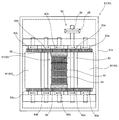
- FIG. 3 is a plan view of the lower mechanism as seen in FIG. 1 in the direction of the arrows of lines III-III.
- FIG. 4 is a plan view of the upper mechanism of FIG.
- FIG. 5 is a perspective view showing one embodiment (a) to (c) of the upper electrode roll mold.
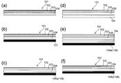
- FIG. 6 is a cross-sectional view of the strip-shaped decorative piece material.
- 7A and 7B are a plan view and a cross-sectional view of the strip-shaped three-dimensional decorative piece, and FIGS.
- FIG. 7A to 7C are three-dimensional decorative pieces manufactured by using the upper electrode roll molds of FIGS. 5A to 5C, respectively. Is shown.
- FIG. 8 is a plan view of a strip-shaped three-dimensional decorative piece having a striped woven gold wire pattern.
- FIG. 9 is a plan view of the strip-shaped three-dimensional decorative piece of FIG. 8 welded to a base material made of cloth, leaving a seam allowance.
- FIG. 10 is a side view showing a configuration of a band-shaped three-dimensional decorative piece manufacturing apparatus according to another embodiment of the present invention.
- FIG. 11 is a plan view of the lower mechanism when FIG. 10 is viewed in the direction of the arrow of the line XI-XI.
- FIG. 12 is a plan view of the upper mechanism of FIG.
- the strip-shaped three-dimensional decorative piece 100 made of the thermoplastic synthetic resin of the present invention and the manufacturing method thereof will be described with reference to the drawings.
- the manufacturing apparatus 10 will be described first, and then desirable embodiments and manufacturing methods of the strip-shaped decorative piece material 101 will be described.
- the thickness of each layer of the band-shaped three-dimensional decorative piece 100 and the band-shaped decorative piece material 101, the unevenness of the mold, the thickness, and the like are emphasized for explanation.
- these shapes, patterns, dimensions, etc. are examples and can be changed as appropriate.
- ⁇ Manufacturing device 10 for strip-shaped three-dimensional decorative piece 100 made of thermoplastic synthetic resin> 1 to 4 show a manufacturing apparatus 10 for manufacturing a strip-shaped three-dimensional decorative piece 100 made of a thermoplastic synthetic resin according to an embodiment of the present invention.
- the manufacturing apparatus 10 includes a delivery mechanism 20 on the upstream side, which is the right-hand side in FIG. 1, a processing mechanism 30 in the center, and a winding mechanism 70 on the downstream side.
- the processing mechanism 30 includes a preheating mechanism 40, a shaping mechanism 50, and a cooling mechanism 60 from the upstream side, and each mechanism is arranged in an upper mechanism 31 and a lower mechanism 32 that can be approached and separated vertically.
- the sending mechanism 20 includes a plurality of sending rolls 21, 22, and 23.
- the delivery rolls are the first to third delivery rolls 21, 22, and 23, and each roll shaft 24 is rotatably attached to the arm 34 attached to the lower frame 32a.
- a part of the lower frame 32a is shown by a dotted line.
- a strip-shaped decorative piece material 101 which will be described later, is wound around the delivery rolls 21, 22, and 23, respectively.
- the strip-shaped decorative piece material 101 is a protection / holding layer 102, an upper layer 103, and a lower layer 104, and is wound around the first to third delivery rolls 21, 22, and 23.
- the number of delivery rolls may be increased accordingly.
- a pulley 25 (only the delivery roll 23 is shown) is mounted on the roll shaft 24, and the V-belt 26 suspended on the pulley 25 is a lower drive mechanism 90 described later. It is connected so that power can be transmitted to.
- the delivery rolls 21, 22, and 23 are rotated in the delivery direction of the strip-shaped decorative piece material 101 by receiving the power of the lower drive mechanism 90.
- the delivery rolls 21, 22, and 23 can also be driven by another drive mechanism.
- the protection / holding layer 102, the upper layer 103, and the lower layer 104 sent out from the respective sending rolls 21, 22, 23 of the sending mechanism 20 are sent to the processing mechanism 30.
- the processing mechanism 30 is provided with a feed roller 35 at the end edge of the lower frame 32a, and the fed protection / holding layer 102, the upper layer 103, and the lower layer 104 are fed with the protection / holding layer 102 facing up. Overlaid with.
- the processing mechanism 30 has a preheating mechanism 40, a shaping mechanism 50, and a cooling mechanism 60 from the upstream side.
- Each mechanism is provided on the upper mechanism 31 and the lower mechanism 32 which are arranged to face each other, and the upper mechanism 31 is configured to be vertically movable relative to the lower mechanism 32.
- an elevating mechanism composed of a cylinder 37 is provided on an arm 36 projecting from the lower frame 32a, and an upper mechanism 31 is attached to the lower end of the cylinder 37 to expand and contract the cylinder 37 to cause an upper mechanism.
- the 31 can be moved up and down.
- the upper mechanism 31 is shown separately from the lower mechanism 32 in FIGS. 1 and 2.
- the upper mechanism 31 is shown. Approaches the lower mechanism 32, and the heat rolls 41 and 42, the electrode molds 51 and 58, and the cooling rolls 61 and 62 move to close positions, respectively.
- the preheating mechanism 40 located on the upstream side of the processing mechanism 30 is a mechanism for preheating and softening the strip-shaped decorative piece material 101.
- the preheating mechanism 40 may be, for example, heat rolls 41, 42 having a built-in heater.
- the heat rolls 41 and 42 are arranged so as to face each other in the vertical direction, and can be rotated in synchronization with the drive mechanisms 80 and 90, which will be described later.
- the upper heat roll 41 is arranged in the upper mechanism 31, and as shown in FIGS. 1 and 4, the upper heat roll 41 is installed so that a part of the peripheral surface protrudes from the lower surface of the upper frame 31a.
- the lower heat roll 42 is arranged in the lower mechanism 32, and as shown in FIGS.
- the lower heat roll 42 is installed so that a part of the peripheral surface protrudes from the window 33a formed on the upper surface of the lower frame 32a.
- the preheating mechanism 40 may be a block-shaped heater instead of the rotatable heat rolls 41 and 42.
- the strip-shaped decorative piece material 101 is sent to the preheating mechanism 40, the strip-shaped decorative piece material 101 is heated and softened by the upper and lower heat rolls 41 and 42. Then, the strip-shaped decorative piece material 101 in the softened state is sent to the shaping mechanism 50 on the downstream side.
- the shaping mechanism 50 is a mechanism for shaping the strip-shaped decorative piece material 101 softened by the preheating mechanism 40 and fusing it as needed.
- the shaping mechanism 50 includes a drum-shaped upper electrode roll mold 51 on the upper side and a lower electrode mold 58 facing the lower side, and high-frequency dielectric heating is performed using these molds 51 and 58 as electrodes.
- the upper electrode roll mold 51 is installed so that a part of the peripheral surface protrudes from the lower surface of the upper frame 31a, and can be rotated by the upper drive mechanism 80 described later. ing.
- the upper electrode roll mold 51 can have, for example, a drum shape having a length of 6 cm to 12 cm and a diameter of 3 cm to 10 cm.
- the upper electrode roll mold 51 is engraved with a pattern 52 and a cutting blade 54 having a sharp tip on the body portion.
- a cushion rubber ring 55 is attached to the edge of the upper electrode roll mold 51 to reduce interference and collision with the lower frame 32a or the lower electrode mold 58 and to provide insulation.
- a fine zigzag pattern is engraved on the body as a pattern 52, and five rows of fusing blades 54 are formed at equal intervals, and a strip-shaped three-dimensional decorative piece described later.
- a zigzag pattern is added to 100 (FIG. 7 (a)).
- the upper electrode roll mold 51 shown in FIG. 5B forms a fusing blade 54 having a height slightly higher than the peripheral surface of the body portion, and a semi-cylindrical strip-shaped solid having a slightly bulging center shown in FIG. 7B.
- the decorative piece 100 can be formed.
- FIG. 5A a fine zigzag pattern is engraved on the body as a pattern 52, and five rows of fusing blades 54 are formed at equal intervals, and a strip-shaped three-dimensional decorative piece described later.
- a zigzag pattern is added to 100 (FIG. 7 (a)).
- the upper electrode roll mold 51 shown in FIG. 5B forms a fusing blade 54 having a height slightly higher than
- a plurality of line pressing ridges 53 having a height lower than that of the fusing blade 54 are provided so as to project, and as shown in FIG. 7 (c), the strip-shaped three-dimensional decorative piece 100 I try to add a streaky line pattern to the.
- these patterns and the fusing blade 54 are examples.
- the upper electrode roll mold 51 has a built-in heater so that shaping and fusing can be easily performed.
- the lower electrode mold 58 arranged below the upper electrode roll mold 51 is installed so that the upper surface is formed flat and the upper surface protrudes from the window 33b formed on the upper surface of the lower frame 32a.
- An insulating cloth 59 is hung on the surface of the lower electrode mold 58 in order to insulate it from the upper electrode roll mold 51 and prevent the occurrence of sparks.
- High-frequency dielectric heating of the strip-shaped decorative piece material 101 is performed between the upper electrode roll mold 51 and the lower electrode mold 58.
- a high-frequency oscillator is built in a control box 11 arranged on the back side of the manufacturing apparatus 10, and the upper electrode roll mold 51 and the lower electrode mold 58 are connected to the high-frequency oscillator.
- the band-shaped decorative piece material 101 softened by the preheating mechanism 40 is sent between the upper electrode roll mold 51 and the lower electrode mold 58 to perform high-frequency dielectric heating, whereby the band-shaped decorative piece material 101 expands and is applied.
- it is blown by the fusing blade 54.
- the cooling mechanism 60 is, for example, cooling rolls 61 and 62, and can be connected to a chilled water circulator (chiller) with a tube to circulate cold water and maintain a low temperature.
- the cooling rolls 61 and 62 are arranged so as to face each other in the vertical direction, and can be rotated in synchronization with the drive mechanisms 80 and 90, which will be described later, respectively.
- the upper cooling roll 61 is arranged in the upper mechanism 31, and as shown in FIGS.
- the upper cooling roll 61 is installed so that a part of the peripheral surface protrudes from the lower surface of the upper frame 31a.
- the lower cooling roll 62 is arranged in the lower mechanism 32, and as shown in FIGS. 1 and 3, the lower cooling roll 62 is installed so that a part of the peripheral surface protrudes from the window 33c formed on the upper surface of the lower frame 32a.
- the cooling mechanism 60 may have a block shape instead of the rotatable cooling rolls 61 and 62.
- the strip-shaped decorative piece material 101 becomes a strip-shaped three-dimensional decorative piece 100 having a fixed shape. Then, the strip-shaped three-dimensional decorative piece 100 is sent out to the winding mechanism 70 through the feed roller 38 provided at the end edge of the lower frame 32a.
- the take-up mechanism 70 includes a take-up roll 71 as shown in FIGS. 1 and 3.
- the roll shaft 72 of the take-up roll 71 is rotatably attached to the arm 39 attached to the lower frame 32a.
- a pulley 73 is attached to the end edge of the roll shaft 72, and the roll shaft 72 rotates under the power of a lower drive mechanism 90 described later via a V-belt 74 suspended on the pulley 73, and winds a strip-shaped three-dimensional decorative piece 100. take.
- the upper heat roll 41, the upper electrode roll mold 51, and the upper cooling roll 61 of the upper mechanism 31 can be rotated by the upper drive mechanism 80.
- the upper drive mechanism 80 can be configured by using one upper speed change motor 81 arranged on the upper frame 31a as a drive source.
- gears 82a, 82b, 82c are provided on the rotating shafts of the upper heat roll 41, the upper electrode roll mold 51, and the upper cooling roll 61, respectively, and gears 82a, 82b and gears 82b, 82c are fed to each other to feed gear 83a.
- 83b are rotatably connected in the same direction.
- a pulley 84 is coaxially provided with the feed gear 83a, and the upper transmission motor 81 is connected by a V-belt 85 to enable power transmission.
- the V-belt 85 rotates the feed gear 83a by driving the upper transmission motor 81, and the upper heat roll 41 and the upper electrode roll are engaged by the meshing of the gears 82a, 83a, 82b, 83b, 82c.
- the mold 51 and the upper cooling roll 61 rotate.
- the upper heat roll 41, the upper electrode roll mold 51, and the upper cooling roll 61 are preferably rotated at the same rotation speed when the outer diameters are the same, in order to prevent the strip-shaped decorative piece material 101 from loosening.
- the lower heat roll 42, the lower cooling roll 62, the delivery rolls 21, 22, 23 and the take-up roll 71 of the lower mechanism 32 can be rotated by the lower drive mechanism 90.
- the lower drive mechanism 90 can be configured by using one lower speed change motor 91 arranged in the lower frame 32a as a drive source.
- gears 92a and 92b are provided on the rotation shafts of the lower heat roll 42 and the lower cooling roll 62, and the gears 92a and 92b are rotatably connected to each other by the feed gears 93a, 93b and 93c in the same direction.
- a pulley 94 is provided coaxially with the feed gear 93a, and the lower transmission motor 91 is connected by a V-belt 95 to enable power transmission.
- the lower heat roll 42 is provided with a pulley 94a coaxially with the gear 92a, and pulleys 25 are also provided on the roll shafts 24 of the delivery rolls 21, 22, and 23, respectively, and a V-belt 26 (third delivery) is provided between the pulleys 94a and 25. Only the roll 23 is shown).
- a pulley 94b is provided on the rotating shaft of the lower cooling roll 62
- a pulley 73 is also provided on the roll shaft 72 of the take-up roll 71
- the pulleys 94b and 73 are connected by a V-belt 74.
- the lower speed change motor 91 by driving the lower speed change motor 91, the lower heat roll 42 and the lower cooling roll 62 rotate in the same direction, and the delivery rolls 21, 22, and 23 are in the delivery direction and winding of the strip-shaped decorative piece material 101.
- the take-roll 71 rotates in the take-up direction of the strip-shaped three-dimensional decorative piece 100.
- the drive mechanisms 80 and 90 are not limited to this embodiment.
- the band-shaped decorative piece material 101 which is the material of the band-shaped three-dimensional decorative piece 100, is a long material including at least the protection / holding layer 102, the upper layer 103, and the lower layer 104, as shown in FIGS. 6A to 6F. It can be configured from, and is wound around the delivery rolls 21, 22, and 23, respectively.
- the layer structure, material, thickness, etc. of the strip-shaped three-dimensional decorative piece 100 are not limited to the following.
- Protective / holding layer 102 A polypropylene film, polyethylene film, etc. that is not melted at high frequencies, and has a thickness of 30 ⁇ m to 100 ⁇ m.
- the protection / holding layer 102 assists in molding and fusing of the thermoplastic synthetic resin of the other layer, and also plays a role of holding the band-shaped three-dimensional decorative piece 100 after molding.
- Upper layer 103 A soft thermoplastic synthetic resin film such as polyvinyl chloride or polyurethane, or a metal-deposited laminated film with metal deposition. Coloring, patterns, and the like can be appropriately printed on the upper layer 103. Examples of printing include roll screen printing, offset printing, gravure printing, and inkjet printing. Further, the film may be a film in which an adhesive layer is interposed on the lower surface of the metal vapor deposition layer and a dye transfer prevention film or a thermoplastic synthetic resin film is laminated. Ethylene-vinyl alcohol copolymer (EVOH) can be exemplified as the anti-transfer film. The dye transfer prevention film prevents dyes such as clothes from being transferred to the surface of the band-shaped three-dimensional decorative piece 100.
- EVOH Ethylene-vinyl alcohol copolymer
- Lower layer 104 Soft sheet of thermoplastic synthetic resin. Examples thereof include soft polyvinyl chloride (PVC) and polyurethane (PU).
- PVC polyvinyl chloride
- PU polyurethane
- FIG. 6A is an example of a strip-shaped decorative piece material 101 having a three-layer structure in which a protective / holding layer 102, an upper layer 103, and a lower layer 104 are laminated.
- the strip-shaped decorative piece material 101 having the layered structure of FIGS. 6 (b) to 6 (f) can be formed.
- Intermediate layer 105 Thermoplastic synthetic resin foam sheet (foam sheet).
- Adhesive layer 106 Double-sided tape 106a or hot melt film 106b.
- Base material 107 Cloth, synthetic leather, synthetic resin sheet.
- the width of the strip-shaped decorative piece material 101 can be appropriately set according to the required width of the strip-shaped three-dimensional decorative piece 100 (the total width in the case of a plurality of rows) and the width of the upper electrode roll mold 51.
- the protection / holding layer 102, the upper layer 103, and the lower layer 104 are wound around the delivery rolls 21, 22, and 23, respectively. Further, in the initial state, the cylinder 37 is reduced and the upper mechanism 31 is located away from the lower mechanism 32.
- the protection / holding layer 102, the upper layer 103, and the lower layer 104 are pulled out to a predetermined length.
- the drawn strip-shaped decorative piece material 101 is overlapped by the feed roller 35, passed between the upper mechanism 31 and the lower mechanism 32, and the tip is attached to the take-up roll 71 via the feed roller 35 with tape or the like. ..
- the heaters of the preheating mechanism 40 and the shaping mechanism 50 are operated to heat the heat rolls 41 and 42, the upper electrode roll mold 51, and the lower electrode mold 58. Further, the cooling mechanism 60 is operated to cool the cooling rolls 61 and 62.
- the upper speed change motor 81 and the lower speed change motor 91 are operated, the cylinder 37 is extended, and the upper mechanism 31 is brought closer to the lower mechanism 32. Further, the shaping mechanism 50 continuously oscillates a high frequency between the upper electrode roll mold 51 and the lower electrode mold 58 to perform high frequency dielectric.
- the drive mechanisms 80 and 90 When the upper speed change motor 81 and the lower speed change motor 91 are operated, the drive mechanisms 80 and 90 have the delivery rolls 21 and 22,23, the heat rolls 41 and 42, the upper electrode roll mold 51, the cooling rolls 61 and 62, and , The take-up roll 71 is rotated.
- the protection / holding layer 102, the upper layer 103, and the lower layer 104 wound around the sending rolls 21, 22, 23 are sent out, and the overlapping strip-shaped decorative pieces are sent out. It is supplied to the processing mechanism 30 as the material 101.
- the strip-shaped decorative piece material 101 is heated between the heat rolls 41 and 42 to be preheated and softened.
- the strip-shaped decorative piece material 101 smoothly passes through the preheating mechanism 40 while undergoing preheating and softening.
- the preheated and softened strip-shaped decorative piece material 101 receives high-frequency dielectric heating between the upper electrode roll mold 51 and the lower electrode mold 58, and is applied to the pattern 52 of the upper electrode roll mold 51. It is shaped and cut to a predetermined width by the fusing blade 54. The protection / holding layer 102 is not blown.
- the shaping mechanism 50 by rotating the upper electrode roll mold 51 in the traveling direction of the strip-shaped decorative piece material 101, the strip-shaped decorative piece material 101 can be smoothly traveled, and shaping and fusing can be performed efficiently. be able to.
- FIG. 7A is a strip-shaped three-dimensional decorative piece 100 to which a zigzag pattern is transferred by the upper electrode roll mold 51 of FIG. 5A.
- FIG. 7B is a strip-shaped three-dimensional decorative piece 100 formed in a semi-cylindrical cross section by the upper electrode roll mold 51 of FIG. 5B.
- FIG. 7 (c) is a strip-shaped three-dimensional decorative piece 100 having a cross section in which streaky dents are formed as a line pattern by the upper electrode roll mold 51 of FIG. 5 (c). Since the upper electrode roll dies 51 of FIGS. 5A to 5C each include five rows of fusing blades 54, four rows of three-dimensional strip-shaped decorative pieces 100 of FIGS. 7A to 7C are formed at the same time. These can be obtained in a state of being held by one protection / holding layer 102.
- the strip-shaped three-dimensional decorative piece 100 invades between the cooling rolls 61 and 62 of the cooling mechanism 60 on the downstream side, receives cooling, and the shape is fixed. Then, by winding on the winding roll 71 by the winding mechanism 70 on the downstream side, a long strip-shaped three-dimensional decorative piece 100 in a form wound on the winding roll 71 can be obtained.
- the obtained strip-shaped three-dimensional decorative piece 100 is used to remove unnecessary ears from the protective / holding layer 102 and cut into an appropriate length to cut a car, a motorcycle, a boat, a home appliance, a game machine, clothing, a bag, etc. It may be attached to an adherend such as a hat.
- the strip-shaped decorative piece material 101 is sequentially fed between the rotating heat rolls 41 and 42, the rotating upper electrode roll mold 51 and the lower electrode roll mold 58, and the rotating cooling rolls 61 and 62 to heat roll.
- Preheated and softened by 41 and 42 continuously shaped by high-frequency dielectric heating in the upper electrode roll mold 51 and lower electrode mold 58, and further shaped by cooling rolls 61 and 62 to form a long strip.
- the three-dimensional decorative piece 100 can be easily manufactured.
- FIG. 8 is an example of a strip-shaped three-dimensional decorative piece 100 with a more complicated striped woven gold wire pattern. Further, as shown in FIG. 9, the strip-shaped three-dimensional decorative piece 100 can be welded to the base material 107 made of cloth leaving a seam allowance.
- FIGS. 10 to 12 are diagrams showing different embodiments of the drive mechanism.
- the upper drive mechanism 80 includes pulleys 86a, 86b, 86c at the end edges of the upper heat roll 41, the upper electrode roll mold 51, and the upper cooling roll 61.
- the pulley 86b is a two-groove pulley.
- the upper speed change motor 81 and the pulley 86b are connected by the V-belt 85
- the pulleys 86a, 86b and the pulleys 86b, 86c are also connected by the V-belt 85a, 85b.
- the lower drive mechanism 90 includes pulleys 96a, 96b, 96c at the edges of the lower heat roll 42 and the lower cooling roll 62, and between them.
- the pulleys 96a, 96b and 96c are two-groove pulleys, respectively.
- the lower speed change motor 91 and the pulley 96b are connected by a V-belt 95, pulleys 96a and 96b, and pulleys 96b and 96c by V-belts 95a and 95b.
- the delivery roll 23 and the like and the take-up roll 71 are connected by V-belts 26 and 74 as in FIG. As a result, by driving the lower speed change motor 91, the lower heat roll 42, the lower cooling roll 62, the delivery rolls 21 to 23, and the take-up roll 71 rotate in synchronization with each other in the same direction.
- Manufacturing equipment 20 Sending mechanism 21-23 Sending roll 30 Processing mechanism 40 Preheating mechanism 41, 42 Heat roll 50 Forming mechanism 51 Upper electrode roll mold 58 Lower electrode mold 60 Cooling mechanism 61, 62 Cooling roll 70 Winding mechanism 71 Winding roll 100 Band-shaped three-dimensional decorative piece 101 Band-shaped decorative piece Material
Landscapes
- Shaping Of Tube Ends By Bending Or Straightening (AREA)
- Lining Or Joining Of Plastics Or The Like (AREA)
- Laminated Bodies (AREA)
Abstract
L'invention concerne un procédé et un dispositif grâce auxquels une longue pièce décorative tridimensionnelle en forme de bande comprenant de la résine synthétique thermoplastique peut être produite. Ce procédé de production d'une longue pièce décorative tridimensionnelle en forme de bande de résine synthétique thermoplastique comprend : une étape d'alimentation dans laquelle un matériau de pièce décorative en forme de bande 101 est distribué ; une étape de préchauffage dans laquelle le matériau de pièce décorative en forme de bande est préchauffé et ramolli à la chaleur ; une étape de mise en forme dans laquelle le matériau de pièce décorative en forme de bande est formé par chauffage diélectrique à haute fréquence et une pièce décorative tridimensionnelle en forme de bande 100 est obtenue, en agençant un moule de rouleau d'électrode supérieure 51 qui tourne et un entraînement, sur le côté supérieur de celui-ci, agençant un moule d'électrode inférieure 58 sous le moule de rouleau d'électrode supérieure, acheminant le matériau de pièce décorative en forme de bande ramolli à la chaleur entre le moule de rouleau d'électrode supérieure et le moule d'électrode inférieure, et en faisant osciller en continu une haute fréquence entre le moule de rouleau d'électrode supérieure et le moule d'électrode inférieure ; une étape de refroidissement dans laquelle la pièce décorative tridimensionnelle en forme de bande formée est refroidie ; et une étape d'enroulement dans laquelle la pièce décorative tridimensionnelle en forme de bande refroidie est enroulée.
Priority Applications (5)
| Application Number | Priority Date | Filing Date | Title |
|---|---|---|---|
| PCT/JP2019/012791 WO2020194496A1 (fr) | 2019-03-26 | 2019-03-26 | Procédé de production et dispositif de production de pièce décorative tridimensionnelle en forme de bande composée de résine synthétique thermoplastique |
| US17/436,038 US11738592B2 (en) | 2019-03-26 | 2019-03-26 | Method for producing a strip of three-dimensional decorative piece made of thermoplastic synthetic resin and apparatus for producing the same |
| EP19921422.2A EP3922479B1 (fr) | 2019-03-26 | 2019-03-26 | Procédé de production et dispositif de production de pièce décorative tridimensionnelle en forme de bande composée de résine synthétique thermoplastique |
| CN201980094672.4A CN113631398A (zh) | 2019-03-26 | 2019-03-26 | 热塑性合成树脂制的带状立体装饰片的制造方法及其制造装置 |
| JP2020553686A JP6847568B2 (ja) | 2019-03-26 | 2019-03-26 | 熱可塑性合成樹脂製の帯状立体装飾片の製造方法及びその製造装置 |
Applications Claiming Priority (1)
| Application Number | Priority Date | Filing Date | Title |
|---|---|---|---|
| PCT/JP2019/012791 WO2020194496A1 (fr) | 2019-03-26 | 2019-03-26 | Procédé de production et dispositif de production de pièce décorative tridimensionnelle en forme de bande composée de résine synthétique thermoplastique |
Publications (1)
| Publication Number | Publication Date |
|---|---|
| WO2020194496A1 true WO2020194496A1 (fr) | 2020-10-01 |
Family
ID=72609350
Family Applications (1)
| Application Number | Title | Priority Date | Filing Date |
|---|---|---|---|
| PCT/JP2019/012791 Ceased WO2020194496A1 (fr) | 2019-03-26 | 2019-03-26 | Procédé de production et dispositif de production de pièce décorative tridimensionnelle en forme de bande composée de résine synthétique thermoplastique |
Country Status (5)
| Country | Link |
|---|---|
| US (1) | US11738592B2 (fr) |
| EP (1) | EP3922479B1 (fr) |
| JP (1) | JP6847568B2 (fr) |
| CN (1) | CN113631398A (fr) |
| WO (1) | WO2020194496A1 (fr) |
Citations (6)
| Publication number | Priority date | Publication date | Assignee | Title |
|---|---|---|---|---|
| GB811580A (en) * | 1956-04-03 | 1959-04-08 | Harry Alexander | Improvements in or relating to the welding of sheet thermoplastic synthetic resinous materials |
| GB1242943A (en) * | 1969-03-22 | 1971-08-18 | Heller William C Jun | A process for thermally joining materials |
| JPS63247023A (ja) * | 1987-04-02 | 1988-10-13 | Noboru Hosokawa | シ−ト材の接合装置および接合方法 |
| JPH0150826B2 (fr) * | 1984-10-09 | 1989-10-31 | Noritsu Kk | |
| JP3235943B2 (ja) | 1995-02-06 | 2001-12-04 | 黒田 暢夫 | 熱可塑性合成樹脂シート製の装飾片の製造方法 |
| JP2008030199A (ja) * | 2004-11-11 | 2008-02-14 | Kuroda Nobuo | 合成樹脂製立体装飾片とその製造方法 |
Family Cites Families (14)
| Publication number | Priority date | Publication date | Assignee | Title |
|---|---|---|---|---|
| FR2602718A1 (fr) * | 1986-07-28 | 1988-02-19 | Lesieur Frederic | Procede et dispositif de dorure marquage en relief a partir d'une impression thermographique realisee a l'aide d'une poudre thermoadhesive |
| JPH01166933A (ja) * | 1987-12-23 | 1989-06-30 | Eiji Kuwabara | 熱可塑性合成樹脂フイルムによる金モール状エンブレムの製造方法 |
| JP2542551B2 (ja) * | 1992-09-07 | 1996-10-09 | 黒田 暢夫 | 熱可塑性合成樹脂製の熱転写装飾片とその製造方法 |
| JPH09155979A (ja) * | 1995-12-08 | 1997-06-17 | Meiwa Sangyo Kk | 高周波加熱を用いた溶着方法及びその装置 |
| JPH10244587A (ja) * | 1997-03-06 | 1998-09-14 | Teijin Ltd | ポリカーボネートフィルムの製造方法 |
| JPH1167102A (ja) * | 1997-08-25 | 1999-03-09 | Kyocera Corp | プラズマディスプレイパネル及びその製造方法 |
| JP4441803B2 (ja) * | 2002-12-12 | 2010-03-31 | 株式会社シーティーイー | 熱可塑性合成樹脂製シート又はフイルムの製造方法およびその装置 |
| JP4036450B2 (ja) * | 2003-04-07 | 2008-01-23 | 日本テトラパック株式会社 | 包装積層材料の製造方法 |
| KR100781932B1 (ko) * | 2005-11-28 | 2007-12-04 | 주식회사 엘지화학 | 천연원목의 외관 및 질감을 가진 합성목재판 패널의 연속식제조방법 및 제조장치 |
| JPWO2011018821A1 (ja) * | 2009-08-11 | 2013-01-17 | 株式会社ディムコ | 平面体押圧装置要素 |
| JP5917462B2 (ja) * | 2013-08-12 | 2016-05-18 | 黒田 暢夫 | 熱可塑性合成樹脂製立体装飾片とその製造方法 |
| JP6450826B1 (ja) * | 2017-12-15 | 2019-01-09 | 日新製鋼株式会社 | 複合体を製造する装置、加圧ロール及び複合体を製造する方法 |
| US20200384797A1 (en) * | 2017-12-27 | 2020-12-10 | Takeshi Kuroda | Three-dimensional decorative piece made of thermoplastic synthetic resin and method for producing the same |
| JP7256564B2 (ja) * | 2019-12-12 | 2023-04-12 | 株式会社 プラスコーポレイション | 立体装飾片及びその製造方法 |
-
2019
- 2019-03-26 JP JP2020553686A patent/JP6847568B2/ja active Active
- 2019-03-26 US US17/436,038 patent/US11738592B2/en active Active
- 2019-03-26 EP EP19921422.2A patent/EP3922479B1/fr active Active
- 2019-03-26 CN CN201980094672.4A patent/CN113631398A/zh active Pending
- 2019-03-26 WO PCT/JP2019/012791 patent/WO2020194496A1/fr not_active Ceased
Patent Citations (6)
| Publication number | Priority date | Publication date | Assignee | Title |
|---|---|---|---|---|
| GB811580A (en) * | 1956-04-03 | 1959-04-08 | Harry Alexander | Improvements in or relating to the welding of sheet thermoplastic synthetic resinous materials |
| GB1242943A (en) * | 1969-03-22 | 1971-08-18 | Heller William C Jun | A process for thermally joining materials |
| JPH0150826B2 (fr) * | 1984-10-09 | 1989-10-31 | Noritsu Kk | |
| JPS63247023A (ja) * | 1987-04-02 | 1988-10-13 | Noboru Hosokawa | シ−ト材の接合装置および接合方法 |
| JP3235943B2 (ja) | 1995-02-06 | 2001-12-04 | 黒田 暢夫 | 熱可塑性合成樹脂シート製の装飾片の製造方法 |
| JP2008030199A (ja) * | 2004-11-11 | 2008-02-14 | Kuroda Nobuo | 合成樹脂製立体装飾片とその製造方法 |
Also Published As
| Publication number | Publication date |
|---|---|
| JP6847568B2 (ja) | 2021-03-24 |
| US20220169066A1 (en) | 2022-06-02 |
| CN113631398A (zh) | 2021-11-09 |
| EP3922479A4 (fr) | 2022-11-16 |
| JPWO2020194496A1 (ja) | 2021-04-30 |
| EP3922479B1 (fr) | 2023-07-19 |
| EP3922479A1 (fr) | 2021-12-15 |
| US11738592B2 (en) | 2023-08-29 |
Similar Documents
| Publication | Publication Date | Title |
|---|---|---|
| CN1217791C (zh) | 用于生产标签的方法和设备 | |
| US2621138A (en) | Method of forming laminated quilted material | |
| KR102658671B1 (ko) | 속셔츠를 연속공정라인으로 제조하는 방법 | |
| KR100821322B1 (ko) | 합성수지시트를 제조하는 장치 및 이에 사용되는 롤러 장치 | |
| JP6847568B2 (ja) | 熱可塑性合成樹脂製の帯状立体装飾片の製造方法及びその製造装置 | |
| JP3640437B2 (ja) | 咬合具付袋の製造方法および製造装置 | |
| CN111886127A (zh) | 伸缩片材、使用该伸缩片材的一次性穿戴物品及其制造方法 | |
| CN109605901A (zh) | 一种覆膜成型工艺、复合膜以及覆膜设备 | |
| KR100297004B1 (ko) | 비닐대지의 엠보싱 성형장치 및 엠보싱 성형방법 | |
| JPH0798361B2 (ja) | フイルムをエンボスする方法 | |
| JP5684582B2 (ja) | 樹脂発泡成形品の製造方法、及び、樹脂発泡成形品の製造設備 | |
| KR101228132B1 (ko) | 리본형 직물 및 리본형 직물의 제조방법 | |
| JP2004136623A (ja) | 単層フィルム製袋装置、単層フィルム接着方法および単層フィルム接着機 | |
| US3567544A (en) | Method of hot melt seaming of fabric materials using a high frequency electric field | |
| KR101519446B1 (ko) | Pvc원단에 부직포를 초음파 융착하는 난방용 장판지 제조방법 | |
| JP2000070172A (ja) | 紙おしぼり製造装置、紙おしぼり包装装置およびこれらを組み合わせた紙おしぼり製品製造設備とその製造方法 | |
| JP4672150B2 (ja) | 発泡装飾シートの製造方法 | |
| KR20230020677A (ko) | 핀홀과 엠보싱을 형성한 단열재 제조를 위한 일체형 제조장치 | |
| JPH08118469A (ja) | エンボスシートの製造方法及び製造装置 | |
| JP5599261B2 (ja) | シート状成形体の製造方法 | |
| JP3586687B2 (ja) | ウエブの融着ラミネート方法および装置 | |
| JP3701433B2 (ja) | 射出成形同時絵付け装置及びその方法 | |
| JP2001287275A (ja) | 3次元造形機 | |
| JP2005113223A (ja) | 金属箔の加熱方法及び加熱装置 | |
| JP2681440B2 (ja) | 合成樹脂製裏シート付きループマットの製造方法 |
Legal Events
| Date | Code | Title | Description |
|---|---|---|---|
| ENP | Entry into the national phase |
Ref document number: 2020553686 Country of ref document: JP Kind code of ref document: A |
|
| 121 | Ep: the epo has been informed by wipo that ep was designated in this application |
Ref document number: 19921422 Country of ref document: EP Kind code of ref document: A1 |
|
| ENP | Entry into the national phase |
Ref document number: 2019921422 Country of ref document: EP Effective date: 20210908 |
|
| NENP | Non-entry into the national phase |
Ref country code: DE |