WO2020194567A1 - Dispositif d'inspection, procédé d'inspection et support lisible par ordinateur non transitoire - Google Patents
Dispositif d'inspection, procédé d'inspection et support lisible par ordinateur non transitoire Download PDFInfo
- Publication number
- WO2020194567A1 WO2020194567A1 PCT/JP2019/013119 JP2019013119W WO2020194567A1 WO 2020194567 A1 WO2020194567 A1 WO 2020194567A1 JP 2019013119 W JP2019013119 W JP 2019013119W WO 2020194567 A1 WO2020194567 A1 WO 2020194567A1
- Authority
- WO
- WIPO (PCT)
- Prior art keywords
- inspected
- mirror
- unit
- objects
- imaging unit
- Prior art date
- Legal status (The legal status is an assumption and is not a legal conclusion. Google has not performed a legal analysis and makes no representation as to the accuracy of the status listed.)
- Ceased
Links
Images









Classifications
-
- G—PHYSICS
- G01—MEASURING; TESTING
- G01N—INVESTIGATING OR ANALYSING MATERIALS BY DETERMINING THEIR CHEMICAL OR PHYSICAL PROPERTIES
- G01N21/00—Investigating or analysing materials by the use of optical means, i.e. using sub-millimetre waves, infrared, visible or ultraviolet light
- G01N21/84—Systems specially adapted for particular applications
- G01N21/88—Investigating the presence of flaws or contamination
- G01N21/90—Investigating the presence of flaws or contamination in a container or its contents
- G01N21/9018—Dirt detection in containers
- G01N21/9027—Dirt detection in containers in containers after filling
-
- G—PHYSICS
- G06—COMPUTING OR CALCULATING; COUNTING
- G06T—IMAGE DATA PROCESSING OR GENERATION, IN GENERAL
- G06T7/00—Image analysis
- G06T7/0002—Inspection of images, e.g. flaw detection
- G06T7/0004—Industrial image inspection
- G06T7/001—Industrial image inspection using an image reference approach
-
- G—PHYSICS
- G01—MEASURING; TESTING
- G01N—INVESTIGATING OR ANALYSING MATERIALS BY DETERMINING THEIR CHEMICAL OR PHYSICAL PROPERTIES
- G01N21/00—Investigating or analysing materials by the use of optical means, i.e. using sub-millimetre waves, infrared, visible or ultraviolet light
- G01N21/84—Systems specially adapted for particular applications
- G01N21/88—Investigating the presence of flaws or contamination
- G01N21/8806—Specially adapted optical and illumination features
-
- G—PHYSICS
- G06—COMPUTING OR CALCULATING; COUNTING
- G06V—IMAGE OR VIDEO RECOGNITION OR UNDERSTANDING
- G06V10/00—Arrangements for image or video recognition or understanding
- G06V10/98—Detection or correction of errors, e.g. by rescanning the pattern or by human intervention; Evaluation of the quality of the acquired patterns
- G06V10/993—Evaluation of the quality of the acquired pattern
-
- G—PHYSICS
- G01—MEASURING; TESTING
- G01N—INVESTIGATING OR ANALYSING MATERIALS BY DETERMINING THEIR CHEMICAL OR PHYSICAL PROPERTIES
- G01N21/00—Investigating or analysing materials by the use of optical means, i.e. using sub-millimetre waves, infrared, visible or ultraviolet light
- G01N21/84—Systems specially adapted for particular applications
- G01N21/88—Investigating the presence of flaws or contamination
- G01N21/8851—Scan or image signal processing specially adapted therefor, e.g. for scan signal adjustment, for detecting different kinds of defects, for compensating for structures, markings, edges
- G01N2021/8887—Scan or image signal processing specially adapted therefor, e.g. for scan signal adjustment, for detecting different kinds of defects, for compensating for structures, markings, edges based on image processing techniques
-
- G—PHYSICS
- G01—MEASURING; TESTING
- G01N—INVESTIGATING OR ANALYSING MATERIALS BY DETERMINING THEIR CHEMICAL OR PHYSICAL PROPERTIES
- G01N21/00—Investigating or analysing materials by the use of optical means, i.e. using sub-millimetre waves, infrared, visible or ultraviolet light
- G01N21/17—Systems in which incident light is modified in accordance with the properties of the material investigated
- G01N21/25—Colour; Spectral properties, i.e. comparison of effect of material on the light at two or more different wavelengths or wavelength bands
- G01N21/251—Colorimeters; Construction thereof
- G01N21/253—Colorimeters; Construction thereof for batch operation, i.e. multisample apparatus
-
- G—PHYSICS
- G06—COMPUTING OR CALCULATING; COUNTING
- G06T—IMAGE DATA PROCESSING OR GENERATION, IN GENERAL
- G06T2207/00—Indexing scheme for image analysis or image enhancement
- G06T2207/30—Subject of image; Context of image processing
- G06T2207/30108—Industrial image inspection
Definitions
- This disclosure relates to an inspection device, an inspection method, and a non-temporary computer-readable medium.
- a general inspection device is configured to determine whether or not the inspected object is a good product by determining whether or not a foreign substance is mixed in the inspected object in which the contained object is contained in the container.
- the inspection device of Patent Document 1 is arranged on the other side of the inspected body while irradiating the inspected body with light by a light source arranged on one side of the inspected body revolving by an inspection rotor.
- the structure is such that the presence or absence of foreign matter is determined based on a plurality of image information acquired by imaging the inspected body by making the image pickup unit follow the revolving inspected body to a certain range.
- the inspection device of Patent Document 1 has a problem that the inspection efficiency of the inspected object is poor because only one inspected object can be imaged simultaneously by one imaging unit.
- One of the objectives to be achieved by the embodiments disclosed herein is to provide an inspection device, an inspection method, and a non-temporary computer-readable medium that contributes to the solution of the problem. It should be noted that this object is only one of the purposes that the embodiments disclosed herein seek to achieve. Other objectives or issues and novel features will be apparent from the description or accompanying drawings herein.
- the inspection device of the first aspect is A mirror having a first reflective portion on the side surface of the tapered first convex portion, A first imaging unit that images a plurality of objects to be inspected arranged around the first reflection unit via the first reflection unit, and A light source that irradiates the object to be inspected with light, A determination unit that determines whether or not the object to be inspected is a non-defective product based on the image information captured by the first imaging unit. To be equipped.
- the inspection method of the second aspect is A plurality of objects to be inspected arranged around a mirror having a first reflecting portion on the side surface of the first convex portion having a tapered shape are irradiated with light.
- the plurality of objects to be inspected are imaged through the first reflecting portion, and the image is taken. Based on the captured image information, it is determined whether or not the inspected object is a non-defective product.
- the non-transitory computer-readable medium of the third aspect is A plurality of objects to be inspected arranged around a mirror having a first reflecting portion on the side surface of the first convex portion having a tapered shape are irradiated with light. The plurality of objects to be inspected are imaged through the first reflecting portion, and the image is taken. A program for causing a computer to determine whether or not the object to be inspected is a non-defective product based on the acquired image information is stored.
- an inspection device an inspection method, and a non-temporary computer-readable medium that can contribute to the improvement of the inspection efficiency of the inspected object.
- FIG. It is a block diagram which shows the minimum structure of the inspection apparatus of Embodiment 1.
- FIG. It is a flowchart which shows the inspection method of Embodiment 1.
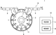
- FIG. It is a figure which shows the specific structure of the inspection apparatus of Embodiment 1.
- FIG. It is a figure for demonstrating the arrangement relation of the body to be inspected, a light source, a mirror, and an image pickup part in the inspection apparatus of Embodiment 1.
- FIG. It is a flowchart which shows the specific flow of the inspection method of Embodiment 1.
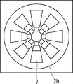
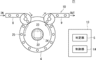
- FIG. It is a figure which shows the acquired image information. It is a figure which shows the specific structure of the inspection apparatus of Embodiment 2.
- FIG. It is a figure for demonstrating the arrangement relation of the body to be inspected, a light source, a mirror, and an image pickup part in Embodiment 2.
- FIG. It is a figure for demonstrating the arrangement relation of the body to be inspected, the light source, the mirror, and the image pickup part in the inspection apparatus of Embodiment 3.
- FIG. It is a figure which shows the specific structure of the inspection apparatus of Embodiment 4.
- the inspection device and the inspection method of the present embodiment it is determined whether or not foreign matter is mixed in the inspected body in which the fluid or powder is sealed in the container, and whether the inspected body is a good product based on the judgment result. Judge whether or not.
- the fluid is, for example, in the form of a liquid, gel or sol.
- a polymer drug such as a swallowing drug or an injection drug is suitable.
- the fluid may be an object that has light transmission and can flow in the container.
- a powdered drug such as a swallowing drug or an injection drug is suitable.
- the powder may be in the form of powder.
- the container is a light-transmitting vial, ampoule, test tube, or the like.
- Foreign substances are objects different from fluids and powders, such as fiber pieces such as clothing, hair falling out of the human body, metal pieces that are parts of production lines such as objects to be inspected, and resin pieces that are fragments of containers. Or a piece of glass.
- FIG. 1 is a block diagram showing a minimum configuration of the inspection device of the present embodiment.
- the inspection device 1 includes a mirror 2, a light source 3, an imaging unit 4, and a determination unit 5.
- the mirror 2 has a reflecting portion on the side surface of the tapered convex portion, which will be described in detail later.
- the light source 3 irradiates the object to be inspected with light.
- the image pickup unit 4 images a plurality of objects to be inspected arranged around the reflection portion of the mirror 2 through the reflection portion.
- the determination unit 5 determines whether or not the object to be inspected is a non-defective product based on the image information captured by the image pickup unit 4.
- FIG. 2 is a flowchart showing the inspection method of the present embodiment.
- the light source 3 irradiates a plurality of objects to be inspected arranged around the reflecting portion of the mirror 2 with light (S1).
- the imaging unit 4 images a plurality of objects to be inspected through the reflecting unit of the mirror 2 (S2).
- the plurality of objects to be inspected are continuously reflected from the time when the plurality of objects to be inspected start to be reflected on the reflection portion of the mirror 2 until the images are finished. It can be imaged.
- the "revolution" is not limited to the case of going around along a circular orbit centered on the mirror 2, but also includes the case of moving a part of the circular orbit.
- the determination unit 5 determines whether or not the inspected object is a non-defective product based on the acquired image information (S3). That is, the determination unit 5 determines the presence or absence of foreign matter mixed in the inspected body based on the acquired image information, and if the inspected body contains foreign matter, the inspected body is considered to be defective. Judgment (YES in S3).
- the determination unit 5 determines whether or not foreign matter is mixed in the inspected body based on the acquired image information, and if the inspected body is not mixed with foreign matter, it is determined that the inspected body is a good product. (NO in S3).
- a plurality of objects to be inspected arranged around the reflection portion can be simultaneously imaged by one imaging unit 4 via the reflection portion of the mirror 2. Therefore, it can contribute to the improvement of the inspection efficiency of the object to be inspected.
- FIG. 3 is a diagram showing a specific configuration of the inspection device of the present embodiment.
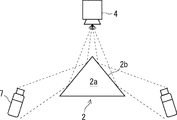
- FIG. 4 is a diagram for explaining the arrangement relationship between the inspected body, the light source, the mirror, and the imaging unit in the inspection device of the present embodiment. In the following description, the side in the direction of gravity will be described as the lower side.
- the inspection device 1 includes a transport unit 6 in addition to the above-mentioned mirror 2, light source 3, image pickup unit 4, and determination unit 5. Then, the inspection device 1 is configured to inspect the inspected body 7 revolving around the mirror 2 by the transport unit 6, for example.
- Such an inspection device 1 is suitable for inspecting an inspected object 7 sealed by a stopper 7c in a state where the fluid 7b is housed inside the transparent container 7a, for example.
- the transport unit 6 is an annular inspection table when viewed from the vertical direction.
- the transport unit 6, the carry-in unit 8, and the carry-out unit 9 form a transport path 10. That is, in the transport path 10, after the transport unit 6 receives the inspected body 7 carried in from the carry-in unit 8 and revolves it, the inspected body 7 is carried out from the transport unit 6 to the carry-out unit 9 and transported.
- the transport unit 6 is provided with a rotating unit 11 that is arranged at substantially equal intervals in the transport unit 6 and that rotates the inspected body 7 around a rotation axis extending in the vertical direction, and is provided with a carry-in unit 8. It is preferable that the inspected body 7 carried in from the above is fixed to the rotating portion 11.
- the rotating unit 11 rotates the object 7 to be inspected for a preset period and then suddenly stops the rotation, so that the fluid 7b is rotated by inertia while stopping the rotation of the container 7a.
- the rotating unit 11 may be configured to continuously rotate the inspected body 7 while the inspected body 7 is being conveyed by the conveying unit 6.
- the rotating portion 11 is provided with a grip portion or the like for fixing the object to be inspected 7 to the rotating portion 11.
- the configuration is not limited to the configuration in which the inspected body 7 is fixed to the rotating portion 11 by gripping the inspected body 7, and any configuration is sufficient as long as the inspected body 7 can rotate on its axis via the rotating portion 11.
- the mirror 2 is provided with a convex portion 2a having a tapered shape upward, and the side surface of the convex portion 2a is a reflection portion 2b.
- the convex portion 2a is formed in an upwardly convex conical shape, for example, as shown in FIGS. 3 and 4. Therefore, the reflecting portion 2b is a conical reflecting surface that is convex upward.
- the central axis of the mirror 2 is generally arranged so as to pass through the center of the transport portion 6.
- the light source 3 emits light in a wavelength range in which the fluid 7b does not deteriorate.
- the fluid 7b is a polymer drug
- light in a wavelength range other than far infrared rays and ultraviolet rays is emitted
- the container 7a is a glass bottle
- light in a near infrared wavelength range having high transmittance of the container 7a is emitted. It is good to emit.
- the light source 3 may emit parallel light.
- the light source 3 is arranged on the opposite side to the side where the mirror 2 is arranged with the transport portion 6 in between when viewed from the vertical direction. That is, the light source 3 is arranged so that the transport unit 6 is arranged between the mirror 2 and the light source 3, and is arranged along the outer circumference of the transport unit 6, for example. Such a light source 3 irradiates the inspected body 7 with light from diagonally below the inspected body 7.
- the image pickup unit 4 is provided with an image sensor such as CMOS (Complementary Metal Oxide Semiconductor) or CCD (Charge Coupled Device), and outputs the acquired image information to the determination unit 5.
- CMOS Complementary Metal Oxide Semiconductor
- CCD Charge Coupled Device
- the image pickup unit 4 is generally arranged so that the central axis of the mirror 2 passes through the center of the image sensor of the image pickup unit 4.
- the imaging unit 4 is arranged so that the entire image of the object to be inspected 7 fits within the angle of view of the imaging unit 4 via the reflecting unit 2b of the mirror 2.
- the arrangement relationship between the mirror 2, the light source 3, the imaging unit 4, and the inspected body 7 is established so that the image pickup unit 4 can take an image of at least a part of the image of the inspected body 7.
- the antireflection unit 12 is arranged around the image pickup unit 4 in order to prevent the light reflected by the reflection unit 2b of the mirror 2 from being reflected in the external environment.
- the antireflection unit 12 is, for example, a black plate, and the image pickup unit 4 is exposed from the through hole 12a formed in the antireflection unit 12.
- the antireflection unit 12 only needs to be able to absorb the light reflected by the mirror 2.
- the determination unit 5 determines whether or not the inspected body 7 is a non-defective product based on the image information acquired as described above, and is provided in the processing device 13, for example, as shown in FIG.
- the processing device 13 includes a control unit 14 in addition to the determination unit 5. Although the details will be described later, the control unit 14 controls the light source 3, the imaging unit 4, the transport path 10, the rotating unit 11, and the like.
- FIG. 5 is a flowchart showing a specific flow of the inspection method of the present embodiment.
- FIG. 6 is a diagram showing the acquired image information. In the following description, it is assumed that a plurality of inspected bodies 7 have already been carried into the transport unit 6 and the inspected body 7 arranged closest to the carry-out unit 9 is carried out immediately after being carried out.
- the control unit 14 controls the transport path 10 to carry the inspected body 7 from the carry-in unit 8 to the transport unit 6, and fixes the inspected body 7 carried into the transport unit 6 to the rotating unit 11 (S11). ).
- the inspected body 7 is fixed to the rotating portion 11 in a standing state (that is, a state in which the lower surface of the inspected body 7 is arranged substantially horizontally).
- the plurality of objects to be inspected 7 are not limited to the case where they are arranged on the side of the reflecting portion 2b of the mirror 2, and may be arranged around the reflecting portion 2b of the mirror 2 when viewed from the vertical direction.
- control unit 14 controls the rotating unit 11 to rotate the inspected body 7 for a preset period, and then suddenly stops the rotation to rotate the fluid 7b by inertia (S12). As a result, the bubbles in the fluid 7b can be extinguished by the vortex of the fluid 7b. Then, the foreign matter can be raised by the vortex of the fluid 7b.
- control unit 14 controls the transport path 10 to rotate the transport unit 6, and the plurality of inspected bodies 7 are arranged at preset positions, respectively.
- the plurality of objects to be inspected 7 are revolved so as to revolve (S13).
- control unit 14 controls the light source 3 to irradiate the object 7 to be inspected with light, and controls the image pickup unit 4 to set a preset position of the transport unit 6 via the reflection unit 2b of the mirror 2.
- the image subject 7 that has reached is imaged by the imaging unit 4 to acquire image information (S14).
- the light source 3 may irradiate light in synchronization with the imaging timing of the imaging unit 4, or may irradiate a plurality of objects 7 to be inspected at all times. That is, it is sufficient that the plurality of objects to be inspected 7 are irradiated with light at the imaging timing of the imaging unit 4.
- the reflecting portion 2b of the mirror 2 since the reflecting portion 2b of the mirror 2 has a conical shape, the images of the plurality of objects 7 to be inspected reflected on the reflecting portion 2b are guided to the imaging unit 4 arranged above the reflecting portion 2b, and the image capturing unit 2b is guided. 4 acquires image information in which a plurality of objects to be inspected 7 as shown in FIG. 6 are arranged radially.
- the image pickup unit 4 can acquire image information in which the lower portion of the inspected body 7 is enlarged.
- the antireflection unit 12 when the antireflection unit 12 is arranged around the image pickup unit 4, it is possible to suppress the light reflected by the reflection unit 2b of the mirror 2 from being reflected in the external environment and incident on the image pickup unit 4, and there is less noise. Image information can be acquired.
- control unit 14 controls the image pickup unit 4 to output the acquired image information from the image pickup unit 4 to the determination unit 5 (S15).
- the control unit 14 controls the image pickup unit 4 to output the acquired image information from the image pickup unit 4 to the determination unit 5 (S15).
- the determination unit 5 creates moving image information of the inspected body 7 when the inspected body 7 carried into the conveying unit 6 is arranged closest to the carrying out unit 9 based on a plurality of image information. Then, based on the created moving image information, it is determined whether or not a foreign substance is mixed in the test object 7 (S16).
- the determination unit 5 images the inspected object 7 at the position I.
- Image information image information in which the inspected object 7 is captured at the position II, image information in which the inspected object 7 is captured in the position III, and an image in which the inspected object 7 is captured at the position IV.
- Information image information in which the inspected object 7 is imaged at the V position, image information in which the inspected object 7 is imaged in the VI position, and image information in which the inspected object 7 is imaged at the VII position.
- the image information captured by the subject 7 at the position VIII and the image information captured by the subject 7 at the position IX are arranged in chronological order to obtain moving image information.
- the moving image information is based on the position information of I to IX. It is preferable to extract the portion of the inspected body 7 in which the subject 7 is to be created from each image information, correct the inclination of the extracted image information, and create the moving image information of the inspected body 7.
- the determination unit 5 compares the pixel values of the adjacent pixels of the first image information among the plurality of image information in the moving image information, and makes a difference of equal to or greater than a preset threshold value with respect to the pixel values of the adjacent pixels.
- a preset threshold value is an absolute value.
- the determination unit 5 tracks the labeled pixel group based on the moving image information and recognizes the moving direction of the pixel group. For example, when there is a pixel group that behaves differently from the preset movement of bubbles. , It is determined that foreign matter is mixed in the object 7 to be inspected.
- the determination unit 5 determines that no foreign matter is mixed in the object 7 to be inspected, for example, when there is no pixel group that behaves differently from the preset movement of bubbles.
- a method for detecting a foreign matter a general foreign matter detecting method can be adopted.
- the imaging unit 4 images the object 7 to be inspected at a frame rate such that the pixel group does not suddenly move in the moving image information and tracking of the pixel group becomes impossible.
- the frame rate of the imaging unit 4 is appropriately set according to the viscosity of the fluid 7b so that the amount of movement of the pixel group for each frame is 1 pixel or less.
- the determination unit 5 determines that the object 7 to be inspected is a defective product and outputs the determination result to the control unit 14.
- the control unit 14 controls, for example, a robot arm (not shown) to remove the inspected body 7 from the transport path 10.
- the determination unit 5 determines that the inspected body 7 is a non-defective product and outputs the determination result to the control unit 14. ..
- the control unit 14 controls the transport path 10 to carry the inspected body 7 from the transport path 6 to the carry-out unit 9. After that, the control unit 14 returns to the process of S11 and controls the transport path 10 to transport the new inspected body 7 to the transport unit 6.
- a plurality of objects to be inspected 7 arranged around the reflection portion 2b via the reflection portion 2b of the mirror 2 are displayed by one imaging unit 4. Images can be taken continuously in series. Therefore, a large amount of information can be acquired by one imaging unit 4, which can contribute to the improvement of the inspection efficiency of the inspected body 7.
- the inspected body 7 in which the fluid 7b is contained in the transparent container 7a is inspected, but the inspected body in which the powder is contained in the transparent container is inspected. You may.
- the light source 3 is arranged so that the surface of the powder can be irradiated with light.
- the images of the plurality of objects to be inspected 7 are guided to the image pickup unit 4 arranged above through the mirror 2, but a plurality of images to be inspected are guided to the image pickup unit arranged below through the mirror. You may guide the image of the body.
- FIG. 7 is a diagram showing a specific configuration of the inspection device of the present embodiment.
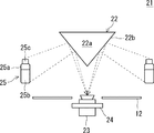
- FIG. 8 is a diagram for explaining the arrangement relationship between the object to be inspected, the light source, the mirror, and the imaging unit in the present embodiment.
- the description overlapping with the first embodiment will be omitted, and the same elements will be described using the same reference numerals.
- the inspection device 21 of the present embodiment has substantially the same configuration as the inspection device 1 of the first embodiment, but as shown in FIGS. 7 and 8, an imaging unit arranged downward via a mirror 22 23 is configured to guide images of a plurality of objects to be inspected 25 irradiated with light by the light source 24.
- Such an inspection device 21 is suitable for inspecting an inspected object 25 sealed with a stopper 25c in a state where the powder 25b is contained in a transparent container 25a, for example.
- the rotating portion 11 of the conveying portion 6 may be omitted and the inspected body 25 may be fixed to the conveying portion 6.
- the device 25 to be inspected may be continuously rotated by the rotating unit 11 while the body 25 to be inspected is being transported by the transport unit 6.
- the mirror 22 is provided with a convex portion 22a having a tapered shape downward, and the side surface of the convex portion 22a is a reflecting portion 22b.
- the convex portion 22a is formed, for example, in a downwardly convex conical shape. Therefore, the reflecting portion 22b is a conical reflecting surface that is convex downward.
- Such a mirror 22 is generally arranged so that the central axis of the mirror 22 passes through the center of the transport portion 6.
- the imaging unit 23 is arranged directly below the mirror 22, for example, as shown in FIGS. 7 and 8. At this time, the image pickup unit 23 is generally arranged so that the central axis of the mirror 22 passes through the center of the image sensor of the image pickup unit 23.
- the imaging unit 23 is arranged so that the entire image of the object to be inspected 25 fits within the angle of view of the imaging unit 23 via the reflecting unit 22b of the mirror 22.
- the arrangement relationship between the mirror 22, the imaging unit 23, the light source 24, and the object 25 to be inspected may be established so that the imaging unit 23 can image at least a part of the image of the object 25 to be inspected.
- the light source 24 is arranged so that at least a part of the portion of the powder 25b reflected on the reflecting portion 22b of the mirror 22 can be irradiated with light.
- the light source 24 may include a ring light arranged so as to surround the image pickup unit 23, and may irradiate substantially the entire upper surface of the powder 25b with light via the reflection portion 22b of the mirror 22.
- the light source 24 is not limited to the ring light, and may be a coaxial light, a dome light, or the like as long as it can irradiate at least a part of the portion of the powder 25b reflected on the reflecting portion 22b of the mirror 22.
- the imaging unit 23 can acquire image information in which the plurality of objects to be inspected 25 are arranged radially. At this time, the image of the object to be inspected 25 reflected by the reflecting unit 22b and guided to the imaging unit 23 is enlarged as the distance from the center of the reflecting unit 22b increases. As a result, the image pickup unit 23 can acquire image information in which the upper part of the inspected body 25 is enlarged. Therefore, when the inspected body 25 is inspected using the inspection device 21 of the present embodiment, for example, foreign matter exposed on the upper surface of the powder 25b can be detected with high accuracy.
- the inspected body 25 in which the powder 25b is contained in the transparent container 25a is inspected, but the inspected body in which the fluid 7b is contained in the transparent container 7a is inspected. 7 may be inspected.
- the light source 24 is arranged so that the light transmitted through the object 7 to be inspected is guided to the reflecting portion 22b of the mirror 22.
- FIG. 9 is a diagram for explaining the arrangement relationship between the inspection body, the light source, the mirror, and the imaging unit in the inspection device of the present embodiment. In the following description, the description overlapping with the first embodiment and the like will be omitted, and the same elements will be described using the same reference numerals.
- the inspection device 31 of the present embodiment has substantially the same configuration as the inspection device 1 of the first embodiment, but as shown in FIG. 9, the first convex portion 32a on which the mirror 32 projects upward and the first convex portion 32a It is configured to include a second convex portion 32b that projects downward.
- the first convex portion 32a is formed, for example, in an upwardly convex conical shape, and the side surface of the first convex portion 32a is the first reflecting portion 32c.
- the second convex portion 32b is formed, for example, in a downwardly convex conical shape, and the side surface of the second convex portion 32b is a second reflecting portion 32d.
- Such a first convex portion 32a and a second convex portion 32b are symmetrically arranged with a horizontal plane in between.
- a first imaging unit 33 arranged directly above the mirror 32 and a second imaging unit 34 arranged directly below the mirror 32 are arranged.
- the first image pickup unit 33 and the second image pickup unit 34 are generally arranged so that the central axis of the mirror 32 passes through the center of the image sensor of the first image pickup unit 33 and the second image pickup unit 34. ing.
- the first imaging unit 33 so that the image of substantially the upper half of the object to be inspected 35 reflected via the first reflecting unit 32c of the mirror 32 fits within the angle of view of the first imaging unit 33. It is located in.
- the second imaging unit 34 so that the image of the substantially lower half of the object to be inspected 35 reflected via the second reflecting unit 32d of the mirror 32 fits within the angle of view of the second imaging unit 34. It is located in.
- the first imaging unit 33 and the second imaging unit 34 are controlled by the control unit 14 so that the imaging timings are synchronized. At this time, the arrangement relationship between the mirror 32 and the inspected body 35 is established so that the inspected body 35 is not reflected in the upper end portion of the first convex portion 32a and the lower end portion of the second convex portion 32b. It is good.
- the first imaging unit 33 acquires image information in which substantially the upper half of the plurality of objects to be inspected 35 are arranged radially. be able to.
- the second imaging unit 34 can acquire image information in which substantially the lower half of the plurality of objects to be inspected 35 is arranged radially.
- the determination unit 5 for example, combines the image information captured by the first imaging unit 33 and the second imaging unit 34 in synchronization, and the image information of the plurality of objects to be inspected 35 that are vertically integrated. To get. Then, the determination unit 5 determines whether or not foreign matter is mixed in the object to be inspected 35 based on the vertically integrated image information.
- the determination unit 5 acquires the image information acquired by the first imaging unit 33 and the image information acquired by the second imaging unit 34 by each of the first imaging units 33 without vertically integrating them. Based on the image information and the image information acquired by the second imaging unit 34, it may be determined whether or not foreign matter is mixed in the object to be inspected 35.
- the substantially upper half of the inspected body 35 is imaged through the first reflecting portion 32c, and the substantially lower half of the inspected body 35 is imaged through the second reflecting portion 32d. It is possible to improve the resolution on the side where the inspected object is tapered in the acquired image information as compared with the case where the entire inspected object 7 and 25 are imaged through one reflecting portion 2b and 22b such as 2 and 2. it can.
- the light source 36 irradiates the inspected body 35 with light, but the light source 36 transmits the light to the inspected body 35 when the content of the inspected body 35 is a fluid.
- the object to be inspected 35 is arranged so that at least a part of the surface of the object to be inspected 35 is irradiated with light.
- FIG. 10 is a diagram showing a specific configuration of the inspection device of the present embodiment. In the following description, the description overlapping with the first embodiment and the like will be omitted, and the same elements will be described using the same reference numerals.
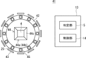
- the inspection device 41 of the present embodiment is suitable for inspecting an inspected body 25 sealed with a stopper 25c in a state where the powder 25b is contained in a transparent container 25a, for example.
- the inspection device 41 has substantially the same configuration as the inspection device 1 of the first embodiment, but the transport unit 42, the light source 43, and the mirror 44 are different.
- the transport unit 42 is independent of the transport path 10 of the inspected body 25 as described above.
- the transport unit 42 is provided with vibrating units 45 at substantially equal intervals, and for example, a plurality of objects to be inspected 25 carried in by a robot arm or the like are fixed to the vibrating unit 45. It is good.
- the vibrating unit 45 vibrates the object to be inspected 25 in the vertical direction or the horizontal direction.
- Such a transport unit 42 revolves the inspected body 25 so that the plurality of inspected bodies 25 are arranged at preset positions.
- the light source 43 can irradiate substantially the entire upper surface of the powder 25b of each of the objects to be inspected 25 with light in a state where the plurality of objects to be inspected 25 are arranged at preset positions. , It is arranged in the vicinity of the preset position. However, the light source 43 may be arranged so that at least a part of the portion reflected on the reflecting portion 44b of the mirror 44 in the one or more objects to be inspected 25 can be irradiated with light.
- the mirror 44 is provided with a convex portion 44a having a tapered shape upward, and the side surface of the convex portion 44a is a reflection portion 44b.
- the convex portion 44a is formed in an upwardly convex quadrangular pyramid shape, for example, as shown in FIG. 10, and as a result, the reflective portion 44b includes four triangular reflecting surfaces 44c. ..
- Such a mirror 44 is generally arranged so that the central axis of the mirror 44 passes through the center of the transport portion 42.
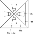
- FIG. 11 is a diagram showing the acquired image information.
- the control unit 14 controls the transport unit 42 to fix a plurality of objects to be inspected 25 transported by a robot arm or the like to the vibrating unit 45.
- control unit 14 controls the vibrating unit 45 to vibrate the inspected body 25 for a preset period, controls the light source 43, irradiates the inspected body 25 with light, and takes an image.
- the unit 4 is controlled so that the image pickup unit 4 takes an image of the vibration of the plurality of objects 25 to be inspected via the reflection unit 44b of the mirror 44. At this time, the image pickup unit 4 continuously acquires image information for the preset period.
- the reflecting portion 44b includes four reflecting surfaces 44c, as shown in FIG. 11, among the plurality of inspected bodies 25, the inspected body 25 facing each of the reflecting surfaces 44c is reflected. However, image information can be acquired.
- the determination unit 5 determines whether or not foreign matter is mixed in the object to be inspected 25 based on the acquired image information.
- the control unit 14 controls the transport unit 42 so that the inspected body 25 adjacent to the inspected body 25 is reflected on the reflection surface 44c, and the plurality of inspected bodies 25 are set in preset positions.
- the inspected body 25 is revolved so as to be arranged in, and the above-mentioned steps are repeated.
- a plurality of objects to be inspected 25 are carried out by a robot arm or the like.
- the inspected body 25 When the inspected body 25 is inspected using such an inspection device 41, the inspected body 25 can be satisfactorily vibrated at a preset position. Therefore, for example, the foreign matter lurking in the powder 25b can be exposed on the upper surface of the powder 25b by vibration to detect the foreign matter.
- the inspected body 25 containing the powder 25b is inspected, but the inspected body 7 containing the fluid 7b may be inspected.
- the transport unit 42 may include the rotating unit 11 instead of the vibrating unit 45.
- the light source 43 may be arranged so that the light transmitted through the object to be inspected 7 is guided to the imaging unit 4.
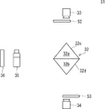
- FIG. 12 is a diagram for explaining the arrangement relationship between the inspected object, the light source, the mirror, the imaging unit, the first wavelength changing unit, and the second wavelength changing unit in the inspection device of the present embodiment.
- the description overlapping with the first embodiment and the like will be omitted, and the same elements will be described using the same reference numerals.
- the inspection device 51 of the present embodiment has substantially the same configuration as the inspection device 31 of the third embodiment, but is arranged between the first reflection unit 32c of the mirror 32 and the first image pickup unit 33. It also includes a first wavelength changing unit 52, and a second wavelength changing unit 53 arranged between the second reflecting unit 32d of the mirror 32 and the second imaging unit 34.
- the light source 36 of the present embodiment emits white light, for example.
- the first wavelength changing unit 52 changes the wavelength characteristics of the light incident on the first imaging unit 33.
- the first wavelength changing unit 52 has, for example, a disk shape and includes a plurality of fan-shaped regions centered on the center of the first wavelength changing unit 52. Then, each fan-shaped region is composed of, for example, different color filters so that the wavelength characteristics can be changed.
- the fan-shaped area may be composed of a bandpass filter. That is, the first wavelength changing unit 52 may change the wavelength characteristics of the light incident on the first imaging unit 33 into a plurality of types. Since the second wavelength changing unit 53 has the same configuration as the first wavelength changing unit 52, a duplicate description will be omitted.
- the wavelength characteristic of the light incident on the first imaging unit 33 and the wavelength characteristic of the light incident on the second imaging unit 34 are equally changed.
- the rotation is controlled so as to be synchronized by the control unit 14.
- control unit 14 has, for example, each time the first imaging unit 33 and the second imaging unit 34 acquire image information (that is, every frame), the first wavelength changing unit 52 and the second wavelength.
- the changing unit 53 is rotated to change the wavelength characteristics of the light incident on the first imaging unit 33 and the wavelength characteristics of the light incident on the second imaging unit 34.
- the determination unit 5 arranges the moving images in chronological order for each image information acquired when the wavelength characteristics of the light incident on the first imaging unit 33 and the wavelength characteristics of the light incident on the second imaging unit 34 are changed equally. Information is created, and based on the created moving image information, it is determined whether or not foreign matter is mixed in the test object 35.
- the inspection device 51 of the present embodiment acquires image information by changing the wavelength characteristics of the light incident on the first imaging unit 33 and the wavelength characteristics of the light incident on the second imaging unit 34. Can be done. Therefore, when a plurality of types of foreign substances mixed in the inspected object 35 can be assumed in advance, the inspected object 35 can be inspected by changing the wavelength characteristics so that each foreign substance can be easily detected. Therefore, the inspection accuracy of the inspected body 35 can be improved.
- the wavelength changing unit may be arranged between the reflecting unit of the mirror and the imaging unit, and the wavelength changing unit can also be used in the inspection devices 1, 21, and 31 of the first to third embodiments.
- FIG. 13 is a diagram for explaining the arrangement relationship between the inspection body, the light source, the mirror, the imaging unit, and the polarizing unit in the inspection device of the present embodiment.
- the description overlapping with the first embodiment and the like will be omitted, and the same elements will be described using the same reference numerals.
- the inspection device 61 of the present embodiment has substantially the same configuration as the inspection device 1 of the first embodiment, but includes a polarizing unit 62 that polarizes the light emitted from the light source 3.
- the polarizing portion 62 is a first polarizing plate 62a arranged between the light source 3 and the object 7 to be inspected, and a second polarizing plate arranged between the object 7 to be inspected and the reflecting portion 2b of the mirror 2.
- 62b is provided, and the polarization axis can be changed by changing the orientation of the first polarizing plate 62a and the second polarizing plate 62b.
- FIG. 14 is a diagram showing an example of a hardware configuration included in the processing device.
- the device 130 shown in FIG. 14 includes a processor 132 and a memory 133 together with the interface 131.
- the processing device 13 described in the above embodiment is realized by the processor 132 reading and executing the program stored in the memory 133. That is, this program is a program for causing the processor 132 to function as the processing device 13 of FIG.
- Non-temporary computer-readable media include various types of tangible storage media.
- Examples of non-transitory computer-readable media include magnetic recording media (eg, flexible disks, magnetic tapes, hard disk drives), magneto-optical recording media (eg, magneto-optical disks).
- this example includes a CD-ROM (Read Only Memory), a CD-R, and a CD-R / W.
- semiconductor memories eg, mask ROM, PROM, EPROM, flash ROM, RAM.
- the program may also be supplied to the computer by various types of transient computer readable medium.
- Examples of temporary computer-readable media include electrical, optical, and electromagnetic waves.
- the temporary computer-readable medium can supply the program to the computer via a wired communication path such as an electric wire and an optical fiber, or a wireless communication path.
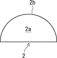
- the reflective portion is formed in a cone shape, but this is not the case.
- the reflecting portion 2b may be a convex curved surface, and as shown in FIG. 16, the reflecting portion 2b may be a concave curved surface.
- the reflecting portion is not limited to the conical shape, but may be a polygonal pyramid shape.
- the shape of the reflecting portion may be any shape that can guide images of a plurality of objects to be inspected to the imaging portion. Therefore, for example, the reflecting portion may have a discontinuous portion in the circumferential direction.
- the reflecting portion may have a shape capable of guiding images of a plurality of forms of the object to be inspected to the imaging portion.
- the reflective unit guides an image in which the lower part of the inspected object is enlarged in a part of the circumferential direction of the reflective portion to the imaging unit, and in other regions, an image in which the upper part of the inspected object is enlarged is displayed.
- the shape is such that it can be guided to the imaging unit.
- the reflection unit it is preferable to acquire the image information of the object to be inspected as a sample in advance through the reflection unit and calibrate the distortion of the image information acquired when inspecting the object to be inspected based on the acquired image information. ..
- the inspected body 7 is inspected in an upright state, but as shown in FIGS. 17 and 18, the inspected body 7 may be inspected in an inclined state.
- the object to be inspected is not vibrated while rotating, but the object to be inspected may be vibrated while rotating. That is, it is sufficient to image a plurality of objects to be inspected through the mirror, and how the inspected object is operated during imaging is not limited, and the inspected object is operated based on a general foreign matter detection method. Just do it. Further, the acquired image information may also be processed based on a general foreign matter detection method.
- the inspection device of the above-described embodiment is configured to include one imaging unit, but if one imaging unit can image a plurality of objects to be inspected, the inspection device may be provided with a plurality of imaging units. Good.
- the light source a general light source can be used, and a laser light source may be used.
- Appendix 1 A mirror having a first reflective portion on the side surface of the tapered first convex portion, A first imaging unit that images a plurality of objects to be inspected arranged around the first reflection unit via the first reflection unit, and A light source that irradiates the object to be inspected with light, A determination unit that determines whether or not the object to be inspected is a non-defective product based on the image information captured by the first imaging unit. Inspector equipped with.
- Appendix 2 When the side in the direction of gravity is the lower side, the first imaging unit is arranged above the mirror.
- a second imaging unit arranged below the mirror is provided.
- the mirror is arranged on the side surface of the first convex portion having a tapered shape upward, and is downward with the first reflecting portion that guides an image of the plurality of objects to be inspected to the first imaging portion.
- the appendix 1 has a second reflecting portion that is arranged on the side surface of the second convex portion having a tapered shape toward the image and guides an image of the plurality of objects to be inspected to the second imaging unit. Inspection device.
- Appendix 6 The inspection device according to any one of Appendix 1 to 5, further comprising a rotating portion that rotates the object to be inspected about a rotation axis extending in the vertical direction when the side in the direction of gravity is the lower side.
- Appendix 7 The inspection device according to any one of Appendix 1 to 6, further comprising a vibrating portion that vibrates the object to be inspected.
- Appendix 10 The inspection device according to Appendix 4, further comprising a second wavelength changing unit that changes the wavelength characteristic of light emitted from the mirror between the mirror and the second imaging unit.
- a plurality of objects to be inspected arranged around a mirror having a first reflecting portion on the side surface of the first convex portion having a tapered shape are irradiated with light.
- the plurality of objects to be inspected are imaged through the first reflecting portion, and the image is taken.
- An inspection method for determining whether or not the object to be inspected is a non-defective product based on the captured image information.
- Appendix 16 The inspection method according to any one of Appendix 12 to 15, wherein when the side in the direction of gravity is the lower side, the plurality of objects to be inspected are conveyed and imaged around the mirror when viewed from the vertical direction.
- Appendix 17 The inspection method according to any one of Appendix 12 to 16, wherein when the side in the direction of gravity is the lower side, the object to be inspected is imaged while rotating around a rotation axis extending in the vertical direction.
- a plurality of objects to be inspected arranged around a mirror having a first reflecting portion on the side surface of the first convex portion having a tapered shape are irradiated with light.
- the plurality of objects to be inspected are imaged through the first reflecting portion, and the image is taken.
- a non-temporary computer-readable medium containing a program that causes a computer to determine whether or not the object to be inspected is a non-defective product based on the acquired image information.
Landscapes
- Engineering & Computer Science (AREA)
- Physics & Mathematics (AREA)
- General Physics & Mathematics (AREA)
- Quality & Reliability (AREA)
- Theoretical Computer Science (AREA)
- Chemical & Material Sciences (AREA)
- Health & Medical Sciences (AREA)
- Life Sciences & Earth Sciences (AREA)
- Analytical Chemistry (AREA)
- Biochemistry (AREA)
- General Health & Medical Sciences (AREA)
- Immunology (AREA)
- Pathology (AREA)
- Computer Vision & Pattern Recognition (AREA)
- Multimedia (AREA)
- Investigating Materials By The Use Of Optical Means Adapted For Particular Applications (AREA)
Abstract
Priority Applications (4)
| Application Number | Priority Date | Filing Date | Title |
|---|---|---|---|
| JP2021508522A JPWO2020194567A1 (fr) | 2019-03-27 | 2019-03-27 | |
| EP19921888.4A EP3951369A4 (fr) | 2019-03-27 | 2019-03-27 | Dispositif d'inspection, procédé d'inspection et support lisible par ordinateur non transitoire |
| US17/441,384 US12148143B2 (en) | 2019-03-27 | 2019-03-27 | Product-inspection apparatus, product-inspection method, and non-transitory computer readable medium |
| PCT/JP2019/013119 WO2020194567A1 (fr) | 2019-03-27 | 2019-03-27 | Dispositif d'inspection, procédé d'inspection et support lisible par ordinateur non transitoire |
Applications Claiming Priority (1)
| Application Number | Priority Date | Filing Date | Title |
|---|---|---|---|
| PCT/JP2019/013119 WO2020194567A1 (fr) | 2019-03-27 | 2019-03-27 | Dispositif d'inspection, procédé d'inspection et support lisible par ordinateur non transitoire |
Publications (1)
| Publication Number | Publication Date |
|---|---|
| WO2020194567A1 true WO2020194567A1 (fr) | 2020-10-01 |
Family
ID=72609658
Family Applications (1)
| Application Number | Title | Priority Date | Filing Date |
|---|---|---|---|
| PCT/JP2019/013119 Ceased WO2020194567A1 (fr) | 2019-03-27 | 2019-03-27 | Dispositif d'inspection, procédé d'inspection et support lisible par ordinateur non transitoire |
Country Status (4)
| Country | Link |
|---|---|
| US (1) | US12148143B2 (fr) |
| EP (1) | EP3951369A4 (fr) |
| JP (1) | JPWO2020194567A1 (fr) |
| WO (1) | WO2020194567A1 (fr) |
Cited By (1)
| Publication number | Priority date | Publication date | Assignee | Title |
|---|---|---|---|---|
| WO2024062533A1 (fr) * | 2022-09-20 | 2024-03-28 | 日本電気株式会社 | Dispositif d'inspection de corps étranger |
Citations (9)
| Publication number | Priority date | Publication date | Assignee | Title |
|---|---|---|---|---|
| JPH0798216A (ja) * | 1993-01-26 | 1995-04-11 | Sony Corp | 半導体装置の外観検査装置とその検査方法 |
| JPH08304012A (ja) * | 1995-05-08 | 1996-11-22 | Omron Corp | 光センサ装置 |
| JPH10148517A (ja) * | 1996-09-17 | 1998-06-02 | Komatsu Ltd | 被検査物の撮像装置および半導体パッケージの検査装置 |
| JPH10227622A (ja) * | 1997-02-14 | 1998-08-25 | Tosok Corp | リードの検査方法及びリード検査装置 |
| JP2000171409A (ja) * | 1998-12-02 | 2000-06-23 | Ntt Fanet Systems Corp | 外観検査方法とその装置 |
| JP2000241363A (ja) * | 1999-02-22 | 2000-09-08 | Mitsubishi Heavy Ind Ltd | 物品の外観検査装置及び外観検査方法 |
| JP2002092797A (ja) * | 2000-09-18 | 2002-03-29 | Nippon Signal Co Ltd:The | 交通情報提供システム |
| JP2006138693A (ja) * | 2004-11-11 | 2006-06-01 | Dainippon Printing Co Ltd | 容器の口部の検査装置 |
| JP4707511B2 (ja) | 2005-09-14 | 2011-06-22 | 株式会社日立情報制御ソリューションズ | 光透過性容器充填液体中の異物検査装置 |
Family Cites Families (17)
| Publication number | Priority date | Publication date | Assignee | Title |
|---|---|---|---|---|
| JPH05152405A (ja) * | 1991-11-28 | 1993-06-18 | Fujitsu Ltd | 外観検査装置 |
| US5452080A (en) | 1993-06-04 | 1995-09-19 | Sony Corporation | Image inspection apparatus and method |
| JP2000298103A (ja) * | 1999-04-15 | 2000-10-24 | Nittetsu Mining Co Ltd | 透明容器内粉末の異物検査装置 |
| JP3793396B2 (ja) * | 2000-05-01 | 2006-07-05 | ダイハツ工業株式会社 | シリンダヘッドの閉塞検査装置 |
| JP2003042734A (ja) * | 2001-07-31 | 2003-02-13 | Ricoh Co Ltd | 表面形状測定方法及び表面形状測定装置 |
| EP1630550A1 (fr) * | 2004-08-27 | 2006-03-01 | Moller & Devicon A/S | Procédé et appareil pour la détection de corps étrangers ou de défauts dans une multitude de conteneurs remplis |
| JP4707632B2 (ja) * | 2005-09-21 | 2011-06-22 | 旭化成エンジニアリング株式会社 | 欠陥検査装置 |
| CN201561936U (zh) * | 2009-06-22 | 2010-08-25 | 皇将科技股份有限公司 | 异物检测装置 |
| JP2011149935A (ja) * | 2009-12-25 | 2011-08-04 | Nihon Yamamura Glass Co Ltd | 容器検査方法および容器検査装置 |
| FR3027391B1 (fr) * | 2014-10-17 | 2024-05-24 | Msc & Sgcc | Procedes, dispositif et ligne d'inspection pour visualiser la planeite d'une surface de bague de recipient |
| CN104359916B (zh) * | 2014-11-17 | 2017-04-12 | 屈桢深 | 基于反射光路设计的瓶装液体异物检测方法和检测装置 |
| JP2016217765A (ja) * | 2015-05-15 | 2016-12-22 | コニカミノルタ株式会社 | 検査装置 |
| TW201740093A (zh) * | 2015-06-03 | 2017-11-16 | 工業動力有限公司 | 使用複數輻射源以檢測容器之系統及方法 |
| JP2018087116A (ja) * | 2016-11-30 | 2018-06-07 | Agcテクノグラス株式会社 | ガラス管 |
| IT201700032261A1 (it) * | 2017-03-23 | 2018-09-23 | Antares Vision S R L | Macchina ispezionatrice |
| US11467261B2 (en) * | 2017-04-21 | 2022-10-11 | Panasonic Intellectual Property Management Co., Ltd. | Distance measuring device and moving object |
| DE102018121573B3 (de) * | 2018-09-04 | 2019-12-24 | Mühlbauer Gmbh & Co. Kg | Inspektionssystem zur inspektion einer mantelfläche eines dreidimensionalen prüfobjekts sowie dessen verwendung und zugehöriges verfahren |
-
2019
- 2019-03-27 JP JP2021508522A patent/JPWO2020194567A1/ja active Pending
- 2019-03-27 EP EP19921888.4A patent/EP3951369A4/fr not_active Withdrawn
- 2019-03-27 WO PCT/JP2019/013119 patent/WO2020194567A1/fr not_active Ceased
- 2019-03-27 US US17/441,384 patent/US12148143B2/en active Active
Patent Citations (9)
| Publication number | Priority date | Publication date | Assignee | Title |
|---|---|---|---|---|
| JPH0798216A (ja) * | 1993-01-26 | 1995-04-11 | Sony Corp | 半導体装置の外観検査装置とその検査方法 |
| JPH08304012A (ja) * | 1995-05-08 | 1996-11-22 | Omron Corp | 光センサ装置 |
| JPH10148517A (ja) * | 1996-09-17 | 1998-06-02 | Komatsu Ltd | 被検査物の撮像装置および半導体パッケージの検査装置 |
| JPH10227622A (ja) * | 1997-02-14 | 1998-08-25 | Tosok Corp | リードの検査方法及びリード検査装置 |
| JP2000171409A (ja) * | 1998-12-02 | 2000-06-23 | Ntt Fanet Systems Corp | 外観検査方法とその装置 |
| JP2000241363A (ja) * | 1999-02-22 | 2000-09-08 | Mitsubishi Heavy Ind Ltd | 物品の外観検査装置及び外観検査方法 |
| JP2002092797A (ja) * | 2000-09-18 | 2002-03-29 | Nippon Signal Co Ltd:The | 交通情報提供システム |
| JP2006138693A (ja) * | 2004-11-11 | 2006-06-01 | Dainippon Printing Co Ltd | 容器の口部の検査装置 |
| JP4707511B2 (ja) | 2005-09-14 | 2011-06-22 | 株式会社日立情報制御ソリューションズ | 光透過性容器充填液体中の異物検査装置 |
Non-Patent Citations (1)
| Title |
|---|
| See also references of EP3951369A4 |
Cited By (2)
| Publication number | Priority date | Publication date | Assignee | Title |
|---|---|---|---|---|
| WO2024062533A1 (fr) * | 2022-09-20 | 2024-03-28 | 日本電気株式会社 | Dispositif d'inspection de corps étranger |
| JPWO2024062533A1 (fr) * | 2022-09-20 | 2024-03-28 |
Also Published As
| Publication number | Publication date |
|---|---|
| JPWO2020194567A1 (fr) | 2020-10-01 |
| EP3951369A1 (fr) | 2022-02-09 |
| US12148143B2 (en) | 2024-11-19 |
| US20220189000A1 (en) | 2022-06-16 |
| EP3951369A4 (fr) | 2022-03-30 |
Similar Documents
| Publication | Publication Date | Title |
|---|---|---|
| CN109791043B (zh) | 用于透明主体的光学检查的方法和装置 | |
| US9329135B2 (en) | Means for inspecting glass containers for defects | |
| CN111556962B (zh) | 容器环状表面的三维几何形状的确定方法、装置和检查线 | |
| KR20150023696A (ko) | 용기 및/또는 그 내용물 내 결함의 x-선 검출 | |
| US20180172602A1 (en) | System and method for inspecting containers using multiple radiation sources | |
| JPH0248859B2 (fr) | ||
| JPS6098340A (ja) | 壜検査装置 | |
| JP4361156B2 (ja) | 物品の外観検査装置 | |
| US20250130176A1 (en) | Visual Inspection Systems for Containers of Liquid Pharmaceutical Products | |
| JP2005017004A (ja) | ガラス瓶の異物検査システム | |
| JP5352444B2 (ja) | 外観検査装置、表面検査装置、及び外観検査方法 | |
| CN208833689U (zh) | 检测设备 | |
| US9535014B1 (en) | Systems and methods for inspecting an object | |
| JP2014062940A (ja) | 検査装置 | |
| JPH0634573A (ja) | 瓶検査装置 | |
| JP5159237B2 (ja) | ガラス容器を検査する装置 | |
| KR100972235B1 (ko) | 거울 광학계를 이용한 용기 측면 촬상 장치 | |
| US12148143B2 (en) | Product-inspection apparatus, product-inspection method, and non-transitory computer readable medium | |
| JP2005017003A (ja) | バイアルの検査システム | |
| CN206804556U (zh) | 一种模具号编码在线成像装置及系统 | |
| JPH08159989A (ja) | 液体密封容器の検査方法および検査装置 | |
| WO2000043757A1 (fr) | Procede et dispositif pour detecter des glacures dans des pieces en matiere translucide ou transparente | |
| JP2002267612A (ja) | 透明容器等の充填液体中の異物検査装置及びシステム | |
| JP2004294097A (ja) | 容器の口部検査装置 | |
| CN105115985A (zh) | 一种灯检机及瓶内杂质检测方法 |
Legal Events
| Date | Code | Title | Description |
|---|---|---|---|
| 121 | Ep: the epo has been informed by wipo that ep was designated in this application |
Ref document number: 19921888 Country of ref document: EP Kind code of ref document: A1 |
|
| ENP | Entry into the national phase |
Ref document number: 2021508522 Country of ref document: JP Kind code of ref document: A |
|
| NENP | Non-entry into the national phase |
Ref country code: DE |
|
| ENP | Entry into the national phase |
Ref document number: 2019921888 Country of ref document: EP Effective date: 20211027 |
|
| WWW | Wipo information: withdrawn in national office |
Ref document number: 2019921888 Country of ref document: EP |