WO2020194656A1 - Machine de travail à déplacement autonome et station de charge - Google Patents
Machine de travail à déplacement autonome et station de charge Download PDFInfo
- Publication number
- WO2020194656A1 WO2020194656A1 PCT/JP2019/013571 JP2019013571W WO2020194656A1 WO 2020194656 A1 WO2020194656 A1 WO 2020194656A1 JP 2019013571 W JP2019013571 W JP 2019013571W WO 2020194656 A1 WO2020194656 A1 WO 2020194656A1
- Authority
- WO
- WIPO (PCT)
- Prior art keywords
- power receiving
- vehicle body
- charging station
- terminal
- power transmission
- Prior art date
- Legal status (The legal status is an assumption and is not a legal conclusion. Google has not performed a legal analysis and makes no representation as to the accuracy of the status listed.)
- Ceased
Links
Images



Classifications
-
- G—PHYSICS
- G05—CONTROLLING; REGULATING
- G05D—SYSTEMS FOR CONTROLLING OR REGULATING NON-ELECTRIC VARIABLES
- G05D1/00—Control of position, course, altitude or attitude of land, water, air or space vehicles, e.g. using automatic pilots
- G05D1/02—Control of position or course in two dimensions
- G05D1/021—Control of position or course in two dimensions specially adapted to land vehicles
- G05D1/0212—Control of position or course in two dimensions specially adapted to land vehicles with means for defining a desired trajectory
- G05D1/0225—Control of position or course in two dimensions specially adapted to land vehicles with means for defining a desired trajectory involving docking at a fixed facility, e.g. base station or loading bay
-
- A—HUMAN NECESSITIES
- A01—AGRICULTURE; FORESTRY; ANIMAL HUSBANDRY; HUNTING; TRAPPING; FISHING
- A01D—HARVESTING; MOWING
- A01D34/00—Mowers; Mowing apparatus of harvesters
- A01D34/006—Control or measuring arrangements
- A01D34/008—Control or measuring arrangements for automated or remotely controlled operation
-
- A—HUMAN NECESSITIES
- A01—AGRICULTURE; FORESTRY; ANIMAL HUSBANDRY; HUNTING; TRAPPING; FISHING
- A01D—HARVESTING; MOWING
- A01D34/00—Mowers; Mowing apparatus of harvesters
- A01D34/01—Mowers; Mowing apparatus of harvesters characterised by features relating to the type of cutting apparatus
- A01D34/412—Mowers; Mowing apparatus of harvesters characterised by features relating to the type of cutting apparatus having rotating cutters
- A01D34/63—Mowers; Mowing apparatus of harvesters characterised by features relating to the type of cutting apparatus having rotating cutters having cutters rotating about a vertical axis
- A01D34/76—Driving mechanisms for the cutters
- A01D34/78—Driving mechanisms for the cutters electric
-
- B—PERFORMING OPERATIONS; TRANSPORTING
- B60—VEHICLES IN GENERAL
- B60L—PROPULSION OF ELECTRICALLY-PROPELLED VEHICLES; SUPPLYING ELECTRIC POWER FOR AUXILIARY EQUIPMENT OF ELECTRICALLY-PROPELLED VEHICLES; ELECTRODYNAMIC BRAKE SYSTEMS FOR VEHICLES IN GENERAL; MAGNETIC SUSPENSION OR LEVITATION FOR VEHICLES; MONITORING OPERATING VARIABLES OF ELECTRICALLY-PROPELLED VEHICLES; ELECTRIC SAFETY DEVICES FOR ELECTRICALLY-PROPELLED VEHICLES
- B60L53/00—Methods of charging batteries, specially adapted for electric vehicles; Charging stations or on-board charging equipment therefor; Exchange of energy storage elements in electric vehicles
- B60L53/10—Methods of charging batteries, specially adapted for electric vehicles; Charging stations or on-board charging equipment therefor; Exchange of energy storage elements in electric vehicles characterised by the energy transfer between the charging station and the vehicle
- B60L53/14—Conductive energy transfer
- B60L53/16—Connectors, e.g. plugs or sockets, specially adapted for charging electric vehicles
-
- B—PERFORMING OPERATIONS; TRANSPORTING
- B60—VEHICLES IN GENERAL
- B60L—PROPULSION OF ELECTRICALLY-PROPELLED VEHICLES; SUPPLYING ELECTRIC POWER FOR AUXILIARY EQUIPMENT OF ELECTRICALLY-PROPELLED VEHICLES; ELECTRODYNAMIC BRAKE SYSTEMS FOR VEHICLES IN GENERAL; MAGNETIC SUSPENSION OR LEVITATION FOR VEHICLES; MONITORING OPERATING VARIABLES OF ELECTRICALLY-PROPELLED VEHICLES; ELECTRIC SAFETY DEVICES FOR ELECTRICALLY-PROPELLED VEHICLES
- B60L53/00—Methods of charging batteries, specially adapted for electric vehicles; Charging stations or on-board charging equipment therefor; Exchange of energy storage elements in electric vehicles
- B60L53/30—Constructional details of charging stations
-
- B—PERFORMING OPERATIONS; TRANSPORTING
- B60—VEHICLES IN GENERAL
- B60L—PROPULSION OF ELECTRICALLY-PROPELLED VEHICLES; SUPPLYING ELECTRIC POWER FOR AUXILIARY EQUIPMENT OF ELECTRICALLY-PROPELLED VEHICLES; ELECTRODYNAMIC BRAKE SYSTEMS FOR VEHICLES IN GENERAL; MAGNETIC SUSPENSION OR LEVITATION FOR VEHICLES; MONITORING OPERATING VARIABLES OF ELECTRICALLY-PROPELLED VEHICLES; ELECTRIC SAFETY DEVICES FOR ELECTRICALLY-PROPELLED VEHICLES
- B60L53/00—Methods of charging batteries, specially adapted for electric vehicles; Charging stations or on-board charging equipment therefor; Exchange of energy storage elements in electric vehicles
- B60L53/30—Constructional details of charging stations
- B60L53/35—Means for automatic or assisted adjustment of the relative position of charging devices and vehicles
- B60L53/36—Means for automatic or assisted adjustment of the relative position of charging devices and vehicles by positioning the vehicle
-
- H—ELECTRICITY
- H02—GENERATION; CONVERSION OR DISTRIBUTION OF ELECTRIC POWER
- H02J—ELECTRIC POWER NETWORKS; CIRCUIT ARRANGEMENTS OR SYSTEMS FOR SUPPLYING OR DISTRIBUTING ELECTRIC POWER; SYSTEMS FOR STORING ELECTRIC ENERGY
- H02J7/00—Circuit arrangements for charging or discharging batteries or for supplying loads from batteries
- H02J7/70—Circuit arrangements for charging or discharging batteries or for supplying loads from batteries characterised by the mechanical construction
- H02J7/731—Circuit arrangements for charging or discharging batteries or for supplying loads from batteries characterised by the mechanical construction specially adapted for holding portable devices containing batteries
-
- A—HUMAN NECESSITIES
- A01—AGRICULTURE; FORESTRY; ANIMAL HUSBANDRY; HUNTING; TRAPPING; FISHING
- A01D—HARVESTING; MOWING
- A01D2101/00—Lawn-mowers
-
- B—PERFORMING OPERATIONS; TRANSPORTING
- B60—VEHICLES IN GENERAL
- B60K—ARRANGEMENT OR MOUNTING OF PROPULSION UNITS OR OF TRANSMISSIONS IN VEHICLES; ARRANGEMENT OR MOUNTING OF PLURAL DIVERSE PRIME-MOVERS IN VEHICLES; AUXILIARY DRIVES FOR VEHICLES; INSTRUMENTATION OR DASHBOARDS FOR VEHICLES; ARRANGEMENTS IN CONNECTION WITH COOLING, AIR INTAKE, GAS EXHAUST OR FUEL SUPPLY OF PROPULSION UNITS IN VEHICLES
- B60K1/00—Arrangement or mounting of electrical propulsion units
- B60K1/04—Arrangement or mounting of electrical propulsion units of the electric storage means for propulsion
-
- B—PERFORMING OPERATIONS; TRANSPORTING
- B60—VEHICLES IN GENERAL
- B60L—PROPULSION OF ELECTRICALLY-PROPELLED VEHICLES; SUPPLYING ELECTRIC POWER FOR AUXILIARY EQUIPMENT OF ELECTRICALLY-PROPELLED VEHICLES; ELECTRODYNAMIC BRAKE SYSTEMS FOR VEHICLES IN GENERAL; MAGNETIC SUSPENSION OR LEVITATION FOR VEHICLES; MONITORING OPERATING VARIABLES OF ELECTRICALLY-PROPELLED VEHICLES; ELECTRIC SAFETY DEVICES FOR ELECTRICALLY-PROPELLED VEHICLES
- B60L2200/00—Type of vehicles
- B60L2200/22—Microcars, e.g. golf cars
-
- B—PERFORMING OPERATIONS; TRANSPORTING
- B60—VEHICLES IN GENERAL
- B60L—PROPULSION OF ELECTRICALLY-PROPELLED VEHICLES; SUPPLYING ELECTRIC POWER FOR AUXILIARY EQUIPMENT OF ELECTRICALLY-PROPELLED VEHICLES; ELECTRODYNAMIC BRAKE SYSTEMS FOR VEHICLES IN GENERAL; MAGNETIC SUSPENSION OR LEVITATION FOR VEHICLES; MONITORING OPERATING VARIABLES OF ELECTRICALLY-PROPELLED VEHICLES; ELECTRIC SAFETY DEVICES FOR ELECTRICALLY-PROPELLED VEHICLES
- B60L2200/00—Type of vehicles
- B60L2200/40—Working vehicles
-
- H—ELECTRICITY
- H01—ELECTRIC ELEMENTS
- H01R—ELECTRICALLY-CONDUCTIVE CONNECTIONS; STRUCTURAL ASSOCIATIONS OF A PLURALITY OF MUTUALLY-INSULATED ELECTRICAL CONNECTING ELEMENTS; COUPLING DEVICES; CURRENT COLLECTORS
- H01R13/00—Details of coupling devices of the kinds covered by groups H01R12/70 or H01R24/00 - H01R33/00
- H01R13/46—Bases; Cases
- H01R13/52—Dustproof, splashproof, drip-proof, waterproof, or flameproof cases
- H01R13/5227—Dustproof, splashproof, drip-proof, waterproof, or flameproof cases with evacuation of penetrating liquids
-
- H—ELECTRICITY
- H01—ELECTRIC ELEMENTS
- H01R—ELECTRICALLY-CONDUCTIVE CONNECTIONS; STRUCTURAL ASSOCIATIONS OF A PLURALITY OF MUTUALLY-INSULATED ELECTRICAL CONNECTING ELEMENTS; COUPLING DEVICES; CURRENT COLLECTORS
- H01R13/00—Details of coupling devices of the kinds covered by groups H01R12/70 or H01R24/00 - H01R33/00
- H01R13/62—Means for facilitating engagement or disengagement of coupling parts or for holding them in engagement
- H01R13/629—Additional means for facilitating engagement or disengagement of coupling parts, e.g. aligning or guiding means, levers, gas pressure electrical locking indicators, manufacturing tolerances
- H01R13/631—Additional means for facilitating engagement or disengagement of coupling parts, e.g. aligning or guiding means, levers, gas pressure electrical locking indicators, manufacturing tolerances for engagement only
- H01R13/6315—Additional means for facilitating engagement or disengagement of coupling parts, e.g. aligning or guiding means, levers, gas pressure electrical locking indicators, manufacturing tolerances for engagement only allowing relative movement between coupling parts, e.g. floating connection
-
- H—ELECTRICITY
- H01—ELECTRIC ELEMENTS
- H01R—ELECTRICALLY-CONDUCTIVE CONNECTIONS; STRUCTURAL ASSOCIATIONS OF A PLURALITY OF MUTUALLY-INSULATED ELECTRICAL CONNECTING ELEMENTS; COUPLING DEVICES; CURRENT COLLECTORS
- H01R2103/00—Two poles
-
- Y—GENERAL TAGGING OF NEW TECHNOLOGICAL DEVELOPMENTS; GENERAL TAGGING OF CROSS-SECTIONAL TECHNOLOGIES SPANNING OVER SEVERAL SECTIONS OF THE IPC; TECHNICAL SUBJECTS COVERED BY FORMER USPC CROSS-REFERENCE ART COLLECTIONS [XRACs] AND DIGESTS
- Y02—TECHNOLOGIES OR APPLICATIONS FOR MITIGATION OR ADAPTATION AGAINST CLIMATE CHANGE
- Y02T—CLIMATE CHANGE MITIGATION TECHNOLOGIES RELATED TO TRANSPORTATION
- Y02T10/00—Road transport of goods or passengers
- Y02T10/60—Other road transportation technologies with climate change mitigation effect
- Y02T10/70—Energy storage systems for electromobility, e.g. batteries
-
- Y—GENERAL TAGGING OF NEW TECHNOLOGICAL DEVELOPMENTS; GENERAL TAGGING OF CROSS-SECTIONAL TECHNOLOGIES SPANNING OVER SEVERAL SECTIONS OF THE IPC; TECHNICAL SUBJECTS COVERED BY FORMER USPC CROSS-REFERENCE ART COLLECTIONS [XRACs] AND DIGESTS
- Y02—TECHNOLOGIES OR APPLICATIONS FOR MITIGATION OR ADAPTATION AGAINST CLIMATE CHANGE
- Y02T—CLIMATE CHANGE MITIGATION TECHNOLOGIES RELATED TO TRANSPORTATION
- Y02T10/00—Road transport of goods or passengers
- Y02T10/60—Other road transportation technologies with climate change mitigation effect
- Y02T10/7072—Electromobility specific charging systems or methods for batteries, ultracapacitors, supercapacitors or double-layer capacitors
-
- Y—GENERAL TAGGING OF NEW TECHNOLOGICAL DEVELOPMENTS; GENERAL TAGGING OF CROSS-SECTIONAL TECHNOLOGIES SPANNING OVER SEVERAL SECTIONS OF THE IPC; TECHNICAL SUBJECTS COVERED BY FORMER USPC CROSS-REFERENCE ART COLLECTIONS [XRACs] AND DIGESTS
- Y02—TECHNOLOGIES OR APPLICATIONS FOR MITIGATION OR ADAPTATION AGAINST CLIMATE CHANGE
- Y02T—CLIMATE CHANGE MITIGATION TECHNOLOGIES RELATED TO TRANSPORTATION
- Y02T90/00—Enabling technologies or technologies with a potential or indirect contribution to GHG emissions mitigation
- Y02T90/10—Technologies relating to charging of electric vehicles
- Y02T90/12—Electric charging stations
-
- Y—GENERAL TAGGING OF NEW TECHNOLOGICAL DEVELOPMENTS; GENERAL TAGGING OF CROSS-SECTIONAL TECHNOLOGIES SPANNING OVER SEVERAL SECTIONS OF THE IPC; TECHNICAL SUBJECTS COVERED BY FORMER USPC CROSS-REFERENCE ART COLLECTIONS [XRACs] AND DIGESTS
- Y02—TECHNOLOGIES OR APPLICATIONS FOR MITIGATION OR ADAPTATION AGAINST CLIMATE CHANGE
- Y02T—CLIMATE CHANGE MITIGATION TECHNOLOGIES RELATED TO TRANSPORTATION
- Y02T90/00—Enabling technologies or technologies with a potential or indirect contribution to GHG emissions mitigation
- Y02T90/10—Technologies relating to charging of electric vehicles
- Y02T90/14—Plug-in electric vehicles
Definitions
- the present invention relates to an autonomous traveling work machine and a charging station.
- Patent Document 1 An autonomous driving machine that can move to a charging station by autonomous driving is known.
- the charging station is provided with a terminal portion that projects rearward, and a recess (a pair of power receiving terminals) into which the terminal portion of the charging station can be inserted into a robot lawnmower, which is a kind of autonomous traveling work machine. It is known that the robot lawn mower and the charging station are electrically connected by inserting the terminal portion into the recess, and the battery in the robot lawn mower is charged by the electric power from the charging station. (For example, Patent Document 1).
- the pair of power receiving terminals will be in a conductive state via moisture. If the robot lawnmower and the charging station are connected in this state, the pair of terminals provided on the charging station side may be energized and charging may not be performed properly. In addition, when the terminals on the charging station side are energized, the positive terminals may be corroded due to intermetallic corrosion.
- an object of the present invention is to make it possible to suppress a situation in which a pair of power receiving terminals are electrically connected by moisture.
- an autonomous traveling work machine capable of moving to a charging station by autonomous traveling, it has a vehicle body portion having a traveling function and a pair of power receiving terminals electrically connected to the charging station.
- One of the pair of power receiving terminals is provided on the surface of the autonomous driving machine, and the other is provided at a position sandwiching at least a part of the vehicle body with respect to the one power receiving terminal. ..
- a part of the charging station has a recess that can be entered, and the pair of power receiving terminals are arranged separately in a portion other than the recess and in the recess.
- a vehicle body cover that covers the vehicle body portion is provided, and the pair of power receiving terminals are arranged separately for the vehicle body portion and the vehicle body cover.
- one of the power receiving terminals is characterized in that the contact surface in contact with the charging station faces upward.
- the contact surface is an inclined surface that is inclined obliquely with respect to a horizontal plane.
- the one power receiving terminal has a convex portion extending downward, and the vehicle body cover has a slit through which the convex portion penetrates and electrically connects the convex portion to the vehicle body portion. It is characterized by that.
- the first plug unit that supports one power transmission terminal that is electrically connected to the one power receiving terminal is provided, and the first plug unit is It is characterized by having a drainage portion for discharging water transmitted through one of the power transmission terminals to the outside.
- the first plug unit has an extension member connected to the one power transmission terminal and extending diagonally downward from the power transmission terminal, and the first plug unit covers the one power transmission terminal and the extension member from above and downward. Is open, and the drainage portion is characterized by having a slit for discharging the water flowing diagonally downward along the extension member to the outside.
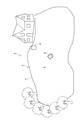
- FIG. 1 is a diagram showing a configuration of an unmanned lawn mowing system according to the present embodiment.
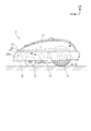
- FIG. 2 is a diagram schematically showing the configuration of a lawnmower.
- FIG. 3 is a diagram showing a state in which the lawnmower and the charging station are electrically connected.
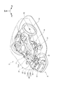
- FIG. 4 is a perspective view of the charging station.
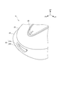
- FIG. 5 is a view of the lawnmower viewed from the front upper side.
- FIG. 6 is a perspective view showing the plug unit and the terminal portion.
- FIG. 7 is a view of the terminal portion viewed from below the lawnmower.
- FIG. 8 is a side sectional view showing a state in which the lawnmower and the charging station are electrically connected.
- FIG. 9 is a diagram showing the positive power receiving terminal together with the peripheral configuration.
- FIG. 10 is a view showing the internal structure of the extension portion of the charging station from diagonally above.
- FIG. 11 is a view showing a side sectional view of the
- FIG. 1 is a diagram showing a configuration of an unmanned lawn mowing system 1 according to the present embodiment.
- the unmanned lawn mower system 1 includes a robot lawn mower 2, an area wire 5 for partitioning a lawn mowing area 4, which is a work area, and a charging station 6.
- the robot lawnmower 2 is an autonomous traveling type working machine that mowes grass while autonomously traveling in the lawn mowing area 4 unmanned, and is an example of an autonomous traveling working machine or a self-propelled working machine. In the following description, the robot lawn mower 2 will be referred to as "lawn mower 2".
- the area wire 5 is arranged so that the lawnmower 2 can detect the boundary A of the lawnmower area 4.
- the area wire 5 is laid along the boundary A and transmits a predetermined signal, and the lawn mower 2 detects the boundary A of the lawn mowing area 4 by detecting the signal from the area wire 5.
- the charging station 6 is a charging device for charging the lawnmower 2 and a device that functions as a standby place where the lawnmower 2 stands by when not working.
- the lawn mower 2 moves to the charging station 6 by autonomous driving at the end of the lawn mowing work, and is charged by the electric power supplied from the charging station 6.
- the area wire 5 transmits a predetermined signal based on the electric power or the signal supplied from the charging station 6.
- FIG. 2 is a diagram schematically showing the configuration of the lawnmower 2.
- the lawnmower 2 includes a vehicle body portion 11 having a traveling function and the like, and a vehicle body cover 21 that covers the vehicle body portion 11.
- Left and right front wheels 12 that can be steered to the left and right are provided in the lower front portion of the vehicle body portion 11, and left and right rear wheels 13 that function as driving wheels are provided in the lower rear portion of the vehicle body portion 11.
- a positive power receiving terminal 25 electrically connected to the charging station 6 is provided on the surface (corresponding to the upper surface) exposed to the outside of the lawnmower 2, and the charging station 6 is provided in front of the lawnmower 2.
- a terminal portion 31 having a negative power receiving terminal 36, which will be described later, is provided. The positive power receiving terminal 25 and the terminal portion 31 will be described later.
- the vehicle body portion 11 serves as a power source for supplying operating power to the left and right traveling motors 15 that individually drive the left and right rear wheels 13, the working portion driving motor 16 that drives the working portion 14, and each part of the lawnmower 2.
- the control unit 30 controls the running of the lawnmower 2 by driving and controlling the traveling motor 15, and performs a predetermined work by driving and controlling the working unit driving motor 16.
- the working unit 14 of the present embodiment is a cutting blade disc provided with a cutting blade, and the lawn mowing work can be performed by rotationally driving the cutting blade disc.
- the control unit 30 specifies the position of the lawn mower 2 based on the detection results of the wheel speed sensor 18 and the sensor unit 19, and controls the running of the lawn mower 2 based on the specified position. As a result, the lawn in the lawn mowing area 4 can be appropriately mowed, and the lawn can be moved to the charging station 6 after the mowing work is completed.
- the known robot lawnmower configuration can be widely applied.
- a technique using a position detection device such as GPS or a gyro sensor, an image recognition technique using a camera, or the like may be applied to the technique for identifying the lawn mowing area 4, the charging station 6, the current position, or the like.
- the vehicle body cover 21 includes a main cover 22 that covers at least the front portion of the vehicle body portion 11, and a top cover 23 that is connected to the main cover 22 from above.
- the main cover 22 is formed of a cover that covers the front, rear, left, and right sides of the vehicle body portion 11 and opens a part of the vehicle body portion 11 upward, and is made of a resin material.
- the top cover 23 is formed on a cover that covers a region of the main cover 22 that opens a part of the vehicle body portion 11, and is made of a resin material.
- These covers 22 and 23 function as a protective cover for preventing rainwater and dust from adhering to the vehicle body 11 and a decorative cover for improving the appearance.
- the body cover 21 is not limited to the one made of resin. Further, when the lawnmower 2 has a small size or the like, the main cover 22 and the top cover 23 may be integrally molded.
- FIG. 3 is a diagram showing a state in which the lawnmower 2 and the charging station 6 are electrically connected.
- the body cover 21 is shown by a two-dot chain line in FIG.
- FIG. 4 is a perspective view of the charging station 6.
- the charging station 6 includes a connection stand 51 to which the lawnmower 2 is connected and a mounting stand 52 on which the lawnmower 2 connected to the connection stand 51 is mounted. ..
- the connection base 51 has an extension portion 51A extending diagonally upward to a position corresponding to the positive power receiving terminal 25 of the lawnmower 2.
- the connection base 51 is provided on a plug unit 53 protruding toward the lawnmower 2 on the mounting base 52 and an extension portion 51A, and is electrically connected to the positive side power receiving terminal 25. 4) and.
- FIG. 5 is a view of the lawn mower 2 as viewed from the front upper side.
- an opening 22K is provided on the front surface of the main cover 22 of the lawnmower 2 so that the plug unit 53 can be inserted toward the terminal portion 31.
- a space 31K into which the plug unit 53 can be inserted is provided between the opening 22K and the terminal 31.
- the opening 22K and the space 31K form a recess 2K that allows the plug unit 53, which is a part of the charging station 6, to be inserted into the terminal 31.
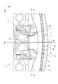
- the positive power receiving terminal 25 is provided at the center position on the left and right sides of the main cover 22, and is exposed in the front upper part of the lawnmower 2.
- the positive power receiving terminal 25 is inclined obliquely with respect to the horizontal plane, and even if moisture such as rainwater adheres to the terminal 25, it can be quickly dropped by the action of gravity.
- FIG. 6 is a perspective view showing the plug unit 53 and the terminal portion 31.
- the plug unit 53 is formed in a triangular shape that narrows toward the rear when viewed from above, and includes a negative power transmission terminal 56. More specifically, the plug unit 53 integrally includes a base end portion 57 connected to the connection base 51 and a unit main body portion 58 having a triangular shape in a top view extending from the base end portion 57.
- the negative power transmission terminal 56 is a terminal that protrudes outward on the left and right sides of the unit main body 58 on one of the left and right surfaces (the surface corresponding to the left side of the lawnmower 2 in this embodiment) and on the tip side of the unit main body 58. It has been formed. Since the negative power transmission terminal 56 is provided on the side surface of the plug unit 53, even if moisture such as rainwater adheres to the plug unit 53, it can be quickly dropped by gravity.
- FIG. 7 is a view of the terminal portion 31 as viewed from below the lawn mower 2.
- FIG. 7 shows a plug unit 53 inserted all the way into the recess 2K by a chain double-dashed line.
- the terminal portion 31 includes a minus side power receiving terminal 36 provided on the vehicle body portion 11 and a pseudo terminal 37 facing the minus side power receiving terminal 36.
- the negative side power receiving terminal 36 is attached to the front protruding portion 11T forming a part of the frontmost portion of the vehicle body portion 11 on the back side of the recess 2K, and is attached to one of the left and right sides (this) in the bottom view shown in FIG.
- the negative power receiving terminal 36 is arranged at a position offset to one of the left and right sides from the left and right center surface M1 of the vehicle body portion 11 (corresponding to the left and right center surfaces of the lawnmower 2), and is a contact surface that contacts the negative power transmission terminal 56. Is formed sideways (to the left in FIG. 7).
- the negative power receiving terminal 36 is provided at a position overlapping the negative power transmission terminal 56 of the plug unit 53 when the plug unit 53 is inserted to the position indicated by the alternate long and short dash line shown in FIG.
- the negative power receiving terminal 36 is curved in a U shape and is deformed so that the contact pressure with the negative power transmission terminal 56 is not excessive, so that the contact state of both terminals 36 and 56 can be appropriately maintained.
- the negative power transmission terminal 56 side may be deformably configured.
- the pseudo terminal 37 facing the negative power receiving terminal 36 and the structure supporting the pseudo terminal 37 are formed symmetrically with the negative power receiving terminal 36 and its peripheral structure. More specifically, the pseudo terminal 37 and its support structure are formed at symmetrical positions and structures with respect to the left and right central surfaces M1 of the vehicle body portion 11. Since the plug unit 53 is inserted between the pseudo terminal 37 and the negative power receiving terminal 36, the lawn mower 2 traveling toward the plug unit 53 can be guided in an appropriate direction, or the negative power receiving terminal can be received. It becomes easy to properly maintain the contact state between the terminal 36 and the negative power transmission terminal 56.
- the terminal portion 31 is provided with a contact portion 39 with which the tip of the plug unit 53 abuts.
- the contact portion 39 is provided at a position where the plug unit 53 comes into contact with the negative power receiving terminal 36 of the terminal portion 31 and the negative power transmission terminal 56 of the plug unit 53 when they are electrically connected to each other.
- the negative power receiving terminal 36 is provided on the inner side of the recess 2K, it is difficult for water-wet grass or raindrops to adhere to the negative power receiving terminal 36.
- the negative side power receiving terminal 36 and the positive side power receiving terminal 25 are arranged separately on the vehicle body cover 21 and the vehicle body portion 11, both terminals 36 and 25?
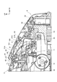
- FIG. 8 is a side sectional view showing a state in which the lawnmower 2 and the charging station 6 are electrically connected.
- the positive power receiving terminal 25 is formed of a metal plate whose upper surface is inclined downward.
- FIG. 9 is a diagram showing the positive power receiving terminal 25 together with the peripheral configuration. As shown in FIG. 9, the positive power receiving terminal 25 has a T-shape in a side view, and a convex portion 25T located at the center of the front and rear of the positive power receiving terminal 25 extends downward.
- the convex portion 25T is inserted into the slit 21S provided in the vehicle body cover 21, and the convex portion 25T penetrates the slit 21S, so that the convex portion 25T is electrically connected to the vehicle body portion 11 in the vehicle body cover 21.
- the positive side power receiving terminal 25 is fixed to the vehicle body cover 21 by hooking the portions of the positive side power receiving terminal 25 located in front of and behind the convex portion 67 on the vehicle body cover 21.
- the main cover 22 is formed with a water receiving portion 68 that receives water that falls downward along the positive power receiving terminal 25, and the main cover 22 collects the water accumulated in the water receiving portion 68.
- An opening 69 for draining water to the outside is provided. The water flowing out from the drainage opening 69 is discharged to the outside of the lawnmower 2 along the upper surface of the main cover 22.
- the positive power receiving terminal 25 is connected to the positive power transmitting terminal 65 provided in the extension 51A when the negative power receiving terminal 36 of the terminal portion 31 and the negative power transmitting terminal 56 of the plug unit 53 are electrically connected. It is provided at the position of contact. As shown in FIG. 8, the contact surfaces where the positive power receiving terminal 25 and the positive power transmission terminal 65 come into contact with each other are inclined surfaces that are inclined diagonally downward in the forward direction, so that moisture is unlikely to remain on each contact surface. , Both terminals 25 and 65 can be easily brought into contact with each other without the intervention of moisture, and intermetallic corrosion can be effectively suppressed.
- the positive side power receiving terminal 25 of the lawn mower 2 has a front upper portion of the vehicle body 11 with respect to the negative power receiving terminal 36 of the lawn mower 2 (reference numerals in FIG. 8). Since it is provided at a position sandwiching the portion (shown by 11X), it is possible to effectively suppress a situation in which the pair of power receiving terminals 25 and 36 are electrically connected by water-wet grass or moisture.
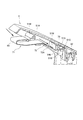
- FIG. 10 is a view showing the internal structure of the extension portion 51A of the charging station 6 from diagonally above
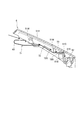
- FIG. 11 is a view showing a side sectional view of the extension portion 51A.
- the extension portion 51A functions as a first plug unit having a positive power transmission terminal 65
- the above-mentioned plug unit 53 functions as a second plug unit having a negative power transmission terminal 56.
- the positive power transmission terminal 65 is formed by bending a part of the conductive member 71 made of a metal plate material.
- the conductive member 71 integrally includes a positive power transmission terminal 65 and an extension member 72 extending diagonally downward from the positive power transmission terminal 65 toward the opposite side of the lawnmower 2 (right side of the paper in FIGS. 10 and 11). I have.
- the rear end of the conductive member 71 (the end on the lawn mower 2 side) is formed in a U-shape that curves rearwardly, and this U-shaped part functions as a positive power transmission terminal 65.
- the conductive member 71 is a plate-shaped first extension portion 72A extending diagonally downward from the positive power transmission terminal 65 toward the front (opposite side of the lawnmower 2) and a first extension portion 72A as extension members 72.
- a flat plate-shaped second extension portion 72B that extends forward and is fastened to the extension portion 51A by the fastening member 73 is integrally provided.
- the extension portion 51A is formed so as to cover the conductive member 71 from above and open at the bottom, and is made of, for example, a resin material.
- the support portion 51B that supports the second extension portion 72B from below and the fastening member 73 is fastened, and the second extension portion 72B supported by the support portion 51B come into contact with each other, and the second extension portion 72B It is integrally provided with a wall portion 51C that rises above.
- the conductive member 71 as shown in FIG. 11, since the positive power transmission terminal 65 is at the highest position among the conductive members 71, moisture such as rainwater from the extension 51A reaches the positive power transmission terminal 65. It does not flow.
- the water when water such as rainwater is blown below the extension portion 51A, the water may adhere to the positive power transmission terminal 65.
- the water flows from the positive power transmission terminal 65 in the order of the first extension 72A and the second extension 72B, so that the positive power transmission terminal Moisture such as rainwater does not easily remain in 65.
- the wall portion 51C abuts on the end surface of the second extension portion 72B opposite to the positive power transmission terminal 65, and dams up the water flowing to the second extension portion 72B.
- the flow of water from the extension portion 51A of the charging station 6 to the front of the extension portion 51A is blocked, and the intrusion of water into the substrate 80 (see FIG. 8) or the like provided in the connection base 51 is prevented.
- a slit 51S (see FIG. 10) recessed downward is provided at the upper end of the wall portion 51C. Therefore, the water dammed by the wall portion 51C is discharged to the outside of the wall portion 51C through the slit 51S.
- the slit 51S functions as a drainage portion for discharging the water from the positive power transmission terminal 65 to the outside.
- the slit 51S is formed at a position close to the side wall of the extension portion 51A, and the water passing through the slit 51S passes through the wall portion 51C and / or the side wall of the extension portion 51A. It travels down and falls down.
- the number of slits 51S is not limited to one, and a plurality of slits 51S may be provided at intervals.
- the side wall of the extension portion 51A may be provided with a through hole or the like for discharging the water that has passed through the slit 51S to the left and right outside of the extension portion 51A.
- reference numeral 82 is a cable ground into which an electric wiring (not shown) extending from the positive power transmission terminal 65 is inserted. The cable gland 82 tightens the electrical wiring to prevent dust and water from entering. Even if the water from the slit 51S flows to the cable gland 82 side, the cable gland 82 is present, so that the water does not enter the wiring portion.
- the extension portion 51A is provided with a plurality of bridge portions 51M for bridging between the left and right side walls of the extension portion 51A in order to secure the strength of the extension portion 51A.
- These cross-linked portions 51M are provided at positions above the conductive member 71 and at a distance from the conductive member 71.
- the upward swing of the conductive member 71 is not blocked by the crosslinked portion 51M, and the positive side power transmission terminal 65 and the positive side power receiving terminal 25 can be easily brought into contact with each other with an appropriate contact pressure. Further, the cross-linked portion 51M does not hinder the flow of water along the upper surface of the conductive member 71, and does not hinder the water falling downward from the conductive member 71.
- one of the pair of power receiving terminals 25 and 36 is provided on the surface of the lawnmower 2, and the other is at least one of the vehicle body portion 11 with respect to one of the power receiving terminals 25. It has a terminal arrangement structure provided at a position sandwiching a portion (front upper portion 11X shown in FIG. 8). According to this structure, even if water-wet grass or water adheres to the power receiving terminal 25 on the surface of the lawn mower 2 during autonomous driving, the water-wet grass or water conducts between the power receiving terminals 25 and 36. It is possible to suppress the situation. Therefore, it is possible to effectively suppress a situation in which the pair of power transmission terminals 65 and 56 are energized and are not properly charged, and intermetallic corrosion.
- the lawn mower 2 has a recess 2K through which the plug unit 53, which is a part of the charging station 6, can enter, and the pair of power receiving terminals 25 and 36 are divided into a portion other than the recess 2K and the inside of the recess 2K. It is possible to further suppress the situation where the power receiving terminals 25 and 36 are connected by water-wet grass or moisture, and the pair of power transmission terminals 65 and 56 are energized and cannot be charged properly. Can be further suppressed. Further, since the pair of power receiving terminals 25 and 36 are distributed and arranged on the vehicle body cover 21 and the vehicle body portion 11, which are different parts among the plurality of parts constituting the lawnmower 2, the moisture is contained at the boundary between the parts. It becomes easier to cancel the move. This also makes it possible to further suppress the situation where the power receiving terminals 25 and 36 are electrically connected to the grass wet with water or moisture, and it is possible to further suppress the situation where the power receiving terminals are not properly charged.
- the pair of power receiving terminals 25 and 36 is not limited to the configuration in which the vehicle body cover 21 and the vehicle body portion 11 are distributed and arranged, and may be distributed and arranged in other different plurality of components constituting the lawnmower 2. Further, since the power receiving terminal 25 provided on the surface of the lawnmower 2 has the contact surface in contact with the charging station 6 facing upward, the power receiving terminal 25 can be easily visually recognized from the outside. In this case, the wiping action between the power transmission terminal 65 on the charging station 6 side makes it easier to clean the upward contact surface of the power receiving terminal 25, and it becomes easier to remove water or the like from the contact surface.
- the contact surface of the power receiving terminal 25 is an inclined surface that is inclined obliquely with respect to the horizontal plane, even if moisture such as rainwater adheres, it can be quickly removed by the action of gravity.
- the power receiving terminal 25 has a convex portion 25T extending downward, and the vehicle body cover 21 has a convex portion 25T penetrating the convex portion 25T into the vehicle body portion 11 in the vehicle body cover 21. Since the slit 21S for electrically connecting is provided, the power receiving terminal 25 and the vehicle body portion 11 can be electrically connected with a simple configuration. The shape of each portion of the power receiving terminal 25 including the convex portion 25T may be appropriately changed.
- the charging station 6 is an extension portion that functions as a first plug unit that supports one of the power transmission terminals 65 that is electrically connected to the power receiving terminal 25 on the surface of the lawnmower 2. Since the extension 51A has a slit 51S that functions as a drainage portion for discharging the water transmitted through the power transmission terminal 65 to the outside, even if water such as rainwater adheres to the power transmission terminal 65, the water content. Can be quickly discharged to the appropriate place.
- the extension portion 51A of the charging station 6 covers the power transmission terminal 65 and the extension member 72 from above and opens downward. Therefore, the extension portion 51A does not prevent the water from falling from the power transmission terminal 65 and the extension member 72. Moreover, since the slit 51S causes the water flowing diagonally downward along the extension member 72 to flow out to the outside, the water adhering to the power transmission terminal 65 and the extension member 72 can be guided to the slit 51S and efficiently discharged. The shape and position of the slit 51S may be changed as appropriate. Further, the drainage portion is not limited to the slit 51S, and a known configuration capable of discharging the water adhering to the power transmission terminal 65 and the extension member 72 may be widely adopted as the drainage portion.
- the above-described embodiment is merely an embodiment of the present invention, and can be arbitrarily modified and applied without departing from the spirit of the present invention.
- the present invention is not limited to this, and the side surface of the lawnmower 2 may be used as appropriate within the range of the surface of the lawnmower 2. It may be placed in a position.
- the power receiving terminal 36 is arranged in the recess 2K at the front of the lawnmower 2 has been described, but the present invention is not limited to this, and the power receiving terminal 36 is within a range of positions where at least a part of the vehicle body portion 11 is sandwiched between the power receiving terminal 25. It may be arranged at an appropriate position.
- the case where the power receiving terminals 25 and 36 are distributed and arranged in the vehicle body cover 21 and the vehicle body portion 11 has been described, but the present invention is not limited to this, and at least a part of the vehicle body portion 11 is sandwiched between the power receiving terminals 25 and 36. You may arrange it on the same member of the vehicle body cover 21 and the vehicle body portion 11 as long as the above.
- the present invention may be applied to other known lawnmowers and charging stations.
- the present invention is not limited to lawnmowers, and the present invention can be applied to various autonomous driving work machines that can move to a charging station by autonomous driving.
- Unmanned lawn mower system Robot lawn mower (autonomous driving work machine) 2K recess 4 grass mowing area 5 area wire 6 charging station 11 body part 12 front wheel 13 rear wheel 14 working part 21 body cover 21S slit 22 main cover 22K opening 23 top cover 25 plus side power receiving terminal 25T plus side power receiving terminal convex part 31 Terminal part 31K Space part 36 Negative side power receiving terminal 37 Pseudo terminal 51 Connection stand 51A Extension part (first plug unit) 51B Support part 51C Wall part 51S Slit (drainage part) 52 Mounting stand 53 Plug unit (second plug unit) 56 Negative side power transmission terminal 58 Unit body 65 Positive side power transmission terminal 71 Conductive member 72A First extension 72B Second extension
Landscapes
- Engineering & Computer Science (AREA)
- Power Engineering (AREA)
- Transportation (AREA)
- Mechanical Engineering (AREA)
- Life Sciences & Earth Sciences (AREA)
- Environmental Sciences (AREA)
- Aviation & Aerospace Engineering (AREA)
- Radar, Positioning & Navigation (AREA)
- Remote Sensing (AREA)
- Physics & Mathematics (AREA)
- General Physics & Mathematics (AREA)
- Automation & Control Theory (AREA)
- Harvester Elements (AREA)
Abstract
La présente invention permet d'empêcher une situation dans laquelle la conduction entre une paire de bornes de réception d'énergie se produit en raison d'eau. Une tondeuse à gazon (2) est pourvue d'une borne parmi une paire de bornes de réception d'énergie (25, 36) sur la surface de la tondeuse à gazon (2) et est pourvue de l'autre borne à une position prenant en sandwich au moins une partie (partie supérieure avant 11X) d'une carrosserie de véhicule (11) conjointement avec la borne de réception d'énergie (25).
Priority Applications (3)
| Application Number | Priority Date | Filing Date | Title |
|---|---|---|---|
| PCT/JP2019/013571 WO2020194656A1 (fr) | 2019-03-28 | 2019-03-28 | Machine de travail à déplacement autonome et station de charge |
| US17/442,223 US12268120B2 (en) | 2019-03-28 | 2019-03-28 | Autonomous travel working machine and charging station |
| EP19920941.2A EP3950412B1 (fr) | 2019-03-28 | 2019-03-28 | Machine de travail à déplacement autonome et station de charge |
Applications Claiming Priority (1)
| Application Number | Priority Date | Filing Date | Title |
|---|---|---|---|
| PCT/JP2019/013571 WO2020194656A1 (fr) | 2019-03-28 | 2019-03-28 | Machine de travail à déplacement autonome et station de charge |
Publications (1)
| Publication Number | Publication Date |
|---|---|
| WO2020194656A1 true WO2020194656A1 (fr) | 2020-10-01 |
Family
ID=72611176
Family Applications (1)
| Application Number | Title | Priority Date | Filing Date |
|---|---|---|---|
| PCT/JP2019/013571 Ceased WO2020194656A1 (fr) | 2019-03-28 | 2019-03-28 | Machine de travail à déplacement autonome et station de charge |
Country Status (3)
| Country | Link |
|---|---|
| US (1) | US12268120B2 (fr) |
| EP (1) | EP3950412B1 (fr) |
| WO (1) | WO2020194656A1 (fr) |
Families Citing this family (2)
| Publication number | Priority date | Publication date | Assignee | Title |
|---|---|---|---|---|
| EP3848274B1 (fr) * | 2020-01-09 | 2023-07-19 | Mobile Industrial Robots A/S | Châssis pour un robot mobile autonome |
| AU2023202495A1 (en) * | 2022-04-25 | 2023-11-09 | Techtronic Cordless Gp | Robotic tool and charging station |
Citations (5)
| Publication number | Priority date | Publication date | Assignee | Title |
|---|---|---|---|---|
| WO2014045830A1 (fr) * | 2012-09-19 | 2014-03-27 | 日産自動車株式会社 | Structure de borne de charge |
| JP2015104256A (ja) * | 2013-11-26 | 2015-06-04 | シャープ株式会社 | 充電装置 |
| WO2017109877A1 (fr) * | 2015-12-24 | 2017-06-29 | 本田技研工業株式会社 | Faucheuse |
| JP6285979B2 (ja) | 2016-03-31 | 2018-02-28 | 本田技研工業株式会社 | 充電ステーションおよび自律走行作業車の充電ステーション誘導装置 |
| JP2018052329A (ja) * | 2016-09-29 | 2018-04-05 | 三菱自動車工業株式会社 | 電動車両の充電口構造 |
Family Cites Families (7)
| Publication number | Priority date | Publication date | Assignee | Title |
|---|---|---|---|---|
| JPS6285979U (fr) | 1985-11-15 | 1987-06-01 | ||
| FR2828589B1 (fr) * | 2001-08-07 | 2003-12-05 | France Telecom | Systeme de connexion electrique entre un vehicule et une station de recharge ou similaire |
| CN102934565B (zh) * | 2011-07-16 | 2015-12-09 | 苏州宝时得电动工具有限公司 | 割草机及对接充电系统 |
| DE102014204091A1 (de) * | 2013-06-18 | 2014-12-18 | Robert Bosch Gmbh | Bearbeitungsmaschine zur autonomen Bearbeitung eines zugeordneten Arbeitsbereichs |
| JPWO2016104187A1 (ja) * | 2014-12-26 | 2017-10-19 | 日立工機株式会社 | 自走式芝刈機 |
| JP2016208885A (ja) * | 2015-04-30 | 2016-12-15 | 日立工機株式会社 | 自走式草刈機 |
| US10498287B2 (en) * | 2017-01-26 | 2019-12-03 | Evermore United S.A. | Waterless cleaning system and method for solar trackers using an autonomous robot |
-
2019
- 2019-03-28 WO PCT/JP2019/013571 patent/WO2020194656A1/fr not_active Ceased
- 2019-03-28 EP EP19920941.2A patent/EP3950412B1/fr active Active
- 2019-03-28 US US17/442,223 patent/US12268120B2/en active Active
Patent Citations (5)
| Publication number | Priority date | Publication date | Assignee | Title |
|---|---|---|---|---|
| WO2014045830A1 (fr) * | 2012-09-19 | 2014-03-27 | 日産自動車株式会社 | Structure de borne de charge |
| JP2015104256A (ja) * | 2013-11-26 | 2015-06-04 | シャープ株式会社 | 充電装置 |
| WO2017109877A1 (fr) * | 2015-12-24 | 2017-06-29 | 本田技研工業株式会社 | Faucheuse |
| JP6285979B2 (ja) | 2016-03-31 | 2018-02-28 | 本田技研工業株式会社 | 充電ステーションおよび自律走行作業車の充電ステーション誘導装置 |
| JP2018052329A (ja) * | 2016-09-29 | 2018-04-05 | 三菱自動車工業株式会社 | 電動車両の充電口構造 |
Non-Patent Citations (1)
| Title |
|---|
| See also references of EP3950412A4 |
Also Published As
| Publication number | Publication date |
|---|---|
| EP3950412A4 (fr) | 2022-04-20 |
| EP3950412A1 (fr) | 2022-02-09 |
| EP3950412B1 (fr) | 2023-07-19 |
| US20220171402A1 (en) | 2022-06-02 |
| US12268120B2 (en) | 2025-04-08 |
Similar Documents
| Publication | Publication Date | Title |
|---|---|---|
| US11260765B2 (en) | Autonomous travel work machine and charging station | |
| US11701979B2 (en) | Robotic work tool system and a charging connector arrangement for a robotic work tool system | |
| US11612914B2 (en) | Cleaning system and method of controlling cleaning system | |
| CN111834800B (zh) | 电气设备 | |
| US20120317745A1 (en) | Autonomous cleaning device | |
| WO2020194656A1 (fr) | Machine de travail à déplacement autonome et station de charge | |
| CN112799390B (zh) | 自移动设备及其工作方法 | |
| CN107205604B (zh) | 自走式吸尘器 | |
| KR20180106225A (ko) | 로봇 청소기 | |
| JP2020068897A (ja) | 清掃ロボット | |
| JP2016208886A (ja) | 草刈機 | |
| US10667464B2 (en) | Mower unit | |
| EP4060449B1 (fr) | Robot de travail | |
| JP2021094000A (ja) | 草刈機 | |
| CN106604672B (zh) | 电动吸尘装置 | |
| US5308114A (en) | Wire cutting device for land vehicles | |
| CN220985280U (zh) | 移动设备及移动系统 | |
| JP7632333B2 (ja) | 草刈り機 | |
| JP7749287B2 (ja) | 作業機のブリーザ構造 | |
| JPH09319435A (ja) | 移動ロボット | |
| JPS6032186Y2 (ja) | ロ−タリ除雪装置における金属異物検知装置 | |
| JP7643368B2 (ja) | 草刈り機 | |
| CN209776610U (zh) | 自动引导车 | |
| JP2586716Y2 (ja) | 電動草刈機の電源装置 | |
| KR20210003204A (ko) | 작업기 |
Legal Events
| Date | Code | Title | Description |
|---|---|---|---|
| 121 | Ep: the epo has been informed by wipo that ep was designated in this application |
Ref document number: 19920941 Country of ref document: EP Kind code of ref document: A1 |
|
| NENP | Non-entry into the national phase |
Ref country code: DE |
|
| ENP | Entry into the national phase |
Ref document number: 2019920941 Country of ref document: EP Effective date: 20211028 |
|
| NENP | Non-entry into the national phase |
Ref country code: JP |
|
| WWG | Wipo information: grant in national office |
Ref document number: 17442223 Country of ref document: US |