WO2020194933A1 - Procédé de commande de déplacement de passerelle d'embarquement de passagers - Google Patents
Procédé de commande de déplacement de passerelle d'embarquement de passagers Download PDFInfo
- Publication number
- WO2020194933A1 WO2020194933A1 PCT/JP2019/049860 JP2019049860W WO2020194933A1 WO 2020194933 A1 WO2020194933 A1 WO 2020194933A1 JP 2019049860 W JP2019049860 W JP 2019049860W WO 2020194933 A1 WO2020194933 A1 WO 2020194933A1
- Authority
- WO
- WIPO (PCT)
- Prior art keywords
- traveling
- angle
- cab
- distance
- rotunda
- Prior art date
- Legal status (The legal status is an assumption and is not a legal conclusion. Google has not performed a legal analysis and makes no representation as to the accuracy of the status listed.)
- Ceased
Links
Images



Classifications
-
- B—PERFORMING OPERATIONS; TRANSPORTING
- B64—AIRCRAFT; AVIATION; COSMONAUTICS
- B64F—GROUND OR AIRCRAFT-CARRIER-DECK INSTALLATIONS SPECIALLY ADAPTED FOR USE IN CONNECTION WITH AIRCRAFT; DESIGNING, MANUFACTURING, ASSEMBLING, CLEANING, MAINTAINING OR REPAIRING AIRCRAFT, NOT OTHERWISE PROVIDED FOR; HANDLING, TRANSPORTING, TESTING OR INSPECTING AIRCRAFT COMPONENTS, NOT OTHERWISE PROVIDED FOR
- B64F1/00—Ground or aircraft-carrier-deck installations
- B64F1/30—Ground or aircraft-carrier-deck installations for embarking or disembarking passengers
- B64F1/305—Bridges extending between terminal building and aircraft, e.g. telescopic, vertically adjustable
- B64F1/3055—Bridges extending between terminal building and aircraft, e.g. telescopic, vertically adjustable with hinged head interface between aircraft and passenger bridge
-
- B—PERFORMING OPERATIONS; TRANSPORTING
- B64—AIRCRAFT; AVIATION; COSMONAUTICS
- B64F—GROUND OR AIRCRAFT-CARRIER-DECK INSTALLATIONS SPECIALLY ADAPTED FOR USE IN CONNECTION WITH AIRCRAFT; DESIGNING, MANUFACTURING, ASSEMBLING, CLEANING, MAINTAINING OR REPAIRING AIRCRAFT, NOT OTHERWISE PROVIDED FOR; HANDLING, TRANSPORTING, TESTING OR INSPECTING AIRCRAFT COMPONENTS, NOT OTHERWISE PROVIDED FOR
- B64F1/00—Ground or aircraft-carrier-deck installations
- B64F1/30—Ground or aircraft-carrier-deck installations for embarking or disembarking passengers
- B64F1/305—Bridges extending between terminal building and aircraft, e.g. telescopic, vertically adjustable
Definitions
- the present invention relates to a traveling control method for a passenger boarding bridge.
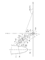
- FIG. 8 is a schematic plan view of a conventional passenger boarding bridge.
- This passenger boarding bridge consists of a Rotanda 4 that is connected to the entrance of the terminal building and supported horizontally around the vertical rotation axis CL1 and a base end that is connected to the Rotanda 4 in an up-and-down manner and can be expanded and contracted. It is provided with a tunnel portion 5, a cab 6 provided at the tip of the tunnel portion 5 and rotatable around a rotation shaft CL2, and a drive column 8 provided near the tip of the tunnel portion 5 to support the tunnel portion 5. ing.
- the tunnel portion 5 is configured to be telescopically fitted with a plurality of tunnels 5a and 5b so as to be expandable and contractible.
- the drive column 8 is provided with an elevating mechanism 10 for moving the tunnel portion 5 up and down.
- an elevating mechanism 10 for moving the tunnel portion 5 up and down.
- the tunnel portion 5 can swing in the vertical direction with the rotunda 4 as the base end.
- a traveling unit 12 having two drive wheels 9 that can independently rotate in the forward and reverse directions is provided.
- the traveling unit 12 is freely configured to travel forward and backward by rotationally driving the two drive wheels 9, and is forward and reverse around the rotation shaft CL3 passing through the center point of the traveling unit 12 (two drive wheels 9). It is configured to be rotatable.
- an angle sensor for detecting an angle sensor for detecting the rotation angle theta R of rotunda 4 (rotunda for angle sensor), the rotation angle phi C cab 6 for the tunnel portion 5 (an angle sensor cab) And an angle sensor (angle sensor for the traveling portion) that detects the rotation angle ⁇ W of the traveling portion 12 with respect to the tunnel portion 5 is provided.
- a horizontal distance measuring means for measuring LW is provided.
- These inclination angle measuring means and horizontal distance measuring means are respectively composed of a range finder for measuring the amount of elevation of the tunnel portion 5 by the elevating mechanism 10 and a range finder for measuring the length of the tunnel portion 5.
- the XYZ Cartesian coordinate system as shown in FIG. 8 is used to calculate the position of each part. That is, as absolute coordinates, the intersection of the rotation axis CL1 of the rotunda 4 and the apron plane is set as the origin (0,0,0), and the X-axis, Y-axis, and Z-axis (axis extending in the vertical direction) are shown in FIG. Take.
- the traveling unit 12 When the movement of such a passenger boarding bridge is automatically controlled from the standby position shown in FIG. 8 to the mounting position where the cab 6 is mounted on the aircraft 3, the traveling unit 12 is controlled as follows.
- the standby position of the traveling unit 12 is P3
- the target position (for example, the mounting position) of the moving destination is P31.
- the control device (not shown) first sets the traveling direction of the traveling unit 12 from the standby position P3 to the target position P31.
- the left and right drive wheels 9 are rotated in the reverse direction on the spot to correct the direction of the drive wheels 9 (FIG. 8 shows the state of the drive wheels 9 after this correction). After that, the traveling unit 12 is made to travel straight from the standby position P3 toward the target position P31.
- the rotation speeds of the two drive wheels 9 are adjusted during traveling.
- the vehicle travels based on the rotation angle ⁇ R of the Rotanda 4 detected by the Rotanda angle sensor sequentially at a predetermined cycle and the horizontal distance LW between the Rotander and the traveling unit measured by the horizontal distance measuring means.
- the current position (coordinates) of the center point (predetermined position on the rotation axis CL3) of the unit 12 is calculated, and the error (positional error) between the calculated current position and the planned current position is calculated.
- the traveling angle indicating the current traveling direction of the traveling unit 12 is calculated, and the error (direction angle error) between the calculated current traveling angle and the angle indicating the traveling target direction is calculated. Then, feedback control is performed to adjust the rotation speeds of the two drive wheels 9 so as to reduce these errors.
- the planned current position is a position at the current time calculated from the planned traveling speed on the traveling target route R1 consisting of a linear route from the standby position P3 to the target position P31.
- the travel target direction is a direction that goes straight from the standby position P3 to the target position P31, and is the same direction as the extension direction of the travel target path R1.
- the traveling target angle ⁇ T is an angle (absolute angle on the apron plane) formed by the traveling target direction (extending direction of the traveling target path R1) and a specific direction (for example, the positive direction of the X axis).
- FIG. 8 shows a case where the traveling angle ⁇ W of the traveling unit 12 is equal to the traveling target angle ⁇ T.
- the rotation speeds of the two drive wheels 9 are adjusted so that these errors (positional errors) become smaller, that is, the actual position approaches the planned position.
- the above position error is divided into a first position error in the travel target direction indicated by the travel target angle ⁇ T and a second position error in the direction orthogonal to the travel target direction. , The rotation speeds of the two drive wheels 9 are adjusted so that the respective positional errors are reduced.
- the rotation speeds of the two drive wheels 9 are adjusted so that the error (direction angle error) between the actual traveling angle ⁇ Wt and the traveling target angle ⁇ T becomes small.
- feedback control is performed to adjust the rotation speeds of the two drive wheels 9 by weighting the three errors of the first position error, the second position error, and the directional angle error, for example. ..
- the center point of the traveling unit 12 moves on the traveling target path R1 in the control calculation. That is, the control device recognizes that the center point of the traveling unit 12 is moving on the traveling target path R1. However, the actual travel route deviates from the travel target route R1. This is mainly due to the linearity of the rotunda angle sensor that detects the rotation angle of the rotunda 4 and the measurement error due to the resolution.
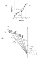
- FIG. 9A is a diagram showing an example of the relationship between the measurement angle by the rotunda angle sensor and the actual angle (true angle).
- the measurement angle is the angle ⁇ R0 as the start of traveling
- the measurement angles are, for example, ⁇ R1 , ⁇ R2 , and ⁇ R3
- the measurement errors are between the actual angles ⁇ R1 , ⁇ R2 , and ⁇ R3. Is occurring.
- FIG. 9 (B) shows the driving of the traveling unit 12 when there is a measurement error as shown by the errors ⁇ R1 , ⁇ R2 , and ⁇ R3 between the measurement angle and the actual angle as shown in FIG. 9 (A).
- FIG. 9B shows an example of the traveling path of a wheel 9.
- the rectangle without hatching is the position of the left and right drive wheels 9 in the control calculation
- the rectangle with hatching is the actual position of the drive wheels 9.
- the measurement angle and the actual angle are both ⁇ R0
- the position of the drive wheel 9 in the control calculation and the actual position of the drive wheel 9 overlap and are the same. There are, but in reality there may be errors.
- the amount of misalignment between the running position (the position of the center point of the running part 12) in the control calculation at a certain point during running and the actual running position is the horizontal distance LW between the rotunda and the running part at the same point and the measurement error ⁇ R. It is roughly proportional to the product of.
- the horizontal distance LW between the rotunda and the traveling portion is relatively large, about 10 to 45 m, the amount of misalignment due to the measurement error ⁇ R becomes large.
- the measurement error ⁇ R fluctuates, and when the traveling unit 12 reaches a target position such as a mounting position when the absolute value of the measurement error ⁇ R is large, There is a problem that the amount of misalignment from the target mounting position becomes large, and there is a risk that the cab 6 cannot be normally mounted on the aircraft 3.
- the present invention has been made to solve the above-mentioned problems, and provides a traveling control method for a passenger boarding bridge that enables a traveling unit to satisfactorily travel straight from a moving start position to a moving destination position. It is intended to be provided.
- the traveling control method of the passenger boarding bridge is a rotanda that is connected to a terminal building and can rotate forward and reverse around the vertical axis, and the base end can be raised and lowered by the rotanda.
- a tunnel portion connected to the tunnel portion and configured to be expandable and contractible in the longitudinal direction, a cab rotatably provided at the tip of the tunnel portion, and the tunnel portion or the cab attached to the tunnel portion or the cab.
- a Rotanda angle sensor that detects an angle
- a traveling unit angle sensor that detects the rotation angle of the traveling unit
- a horizontal distance measuring means for measuring the horizontal distance from the vertical axis to the center point of the traveling unit. It is a traveling control method of a passenger boarding bridge provided with an inclination angle measuring means for measuring an inclination angle of the tunnel portion with respect to a horizontal plane, and when the cab is attached to an aircraft boarding / alighting portion, the traveling portion When is in the movement start position, a step of calculating relative position information indicating the position of the boarding / alighting part as seen from the cab, and the traveling part for mounting the cab on the boarding / alighting part from the movement start position.
- the step of calculating the target angle and the traveling portion are traveled from the moving start position to the moving destination position, and during this traveling, the current traveling direction of the traveling portion and the specific direction are set in a predetermined cycle.
- a traveling angle which is an angle formed, and controlling the traveling portion only so that the traveling angle maintains the traveling target angle, and calculating the position information of the moving destination.
- the position information of the movement start position includes the horizontal distance from the vertical axis measured by the horizontal distance measuring means to the center point of the traveling portion, the rotation angle of the rotor and the inclination measured by the angle sensor for the rotor. Calculated based on the tilt angle measured by the angle measuring means, and the traveling horizontal In the Tep, the traveling angle is calculated based on the rotation angle of the traveling portion measured by the traveling portion angle sensor and the rotation angle of the rotunda measured by the rotunda angle sensor.
- the traveling unit when the traveling unit is at the moving start position, the distance (distance A) from the moving start position to the moving destination position is horizontal from the rotation center (vertical axis) of the Rotanda to the center point of the traveling unit.
- the position information of the moving destination is calculated, the traveling angle is calculated at a predetermined cycle while the traveling unit is traveling, and the traveling angle maintains the traveling target angle.
- the traveling unit is controlled only by the plumb bob.
- the current position of the traveling unit calculated by the measurement error of the rotunda angle sensor and the planned current position of the traveling unit on the traveling target route (the route connecting the movement start position and the movement destination position in a straight line)
- the distance A is shorter than the distance B
- the position deviation from the travel target path of the traveling portion is reduced by controlling only the traveling angle without considering the positional error from the position. Therefore, it becomes possible to satisfactorily travel straight from the movement start position to the movement destination position.
- the movement start position may be a position after or during the movement by some means or cause before that.
- the position of the moving destination may be the position of the traveling portion when the cab is mounted on the boarding / alighting portion.
- the boarding / alighting part is detected based on the image of the boarding / alighting part taken by the camera attached to the cab, and the relative position information of the boarding / alighting part is calculated. Good.
- the traveling unit is configured to have two drive wheels that are arranged parallel to each other with the center point of the traveling unit and capable of independently rotating and driving, and the traveling step is configured to have the two driving wheels.
- the traveling portion may be controlled by adjusting the rotation speed of each of the wheels.
- the distance from the moving start position to the moving destination position is the traveling portion from the vertical axis when the tunnel portion is most contracted. It may be in a state of a predetermined distance or less, which is shorter than the horizontal distance to the center point of.
- the present invention can provide a traveling control method for a passenger boarding bridge, which has the configuration described above and enables the traveling unit to satisfactorily travel straight from a moving start position to a moving destination position. The effect is achieved.
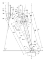
- FIG. 1 is a schematic plan view showing an example of a passenger boarding bridge according to the present embodiment.
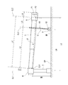
- FIG. 2 is a schematic view of the passenger boarding bridge as viewed from the side.
- FIG. 3 is a front view of the tip of the cab mounted on the aircraft.
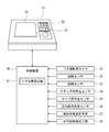
- FIG. 4 is a diagram showing an example of an operation panel and the like.
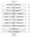
- FIG. 5 is a flowchart showing an example of the operation when the passenger boarding bridge is mounted.
- FIG. 6 is a flowchart showing an example of a method of calculating the control amount in the operation when the passenger boarding bridge is mounted.
- FIG. 7 is a schematic view showing an example of a photographed image of the door photographing camera in the cab in the standby position.
- FIG. 8 is a schematic plan view of a conventional passenger boarding bridge.
- FIG. 9A is a diagram showing an example of the relationship between the measurement angle by the Rotanda angle sensor and the actual angle
- FIG. 9B is a diagram showing the measurement angle and the actual angle as shown in FIG. 9A. It is a figure which shows an example of the actual traveling path of a drive wheel when there is an error between.
- FIG. 1 is a schematic plan view showing an example of a passenger boarding bridge according to the present embodiment.
- FIG. 2 is a schematic view of the passenger boarding bridge shown in FIG. 1 as viewed from the side.
- FIG. 3 is a view of the tip of the cab mounted on the aircraft as viewed from the front (aircraft side).
- FIG. 4 is a diagram showing an example of an operation panel and the like.
- the passenger boarding bridge 1 can apply the traveling control method of the passenger boarding bridge according to the present embodiment.
- the passenger boarding bridge 1 has a horizontally rotatable rotunda (base circular chamber) 4 connected to the entrance 2a of the airport terminal building 2 and a base end connected to the rotunda 4 in an up-and-down manner and can be expanded and contracted in the longitudinal direction. It is provided with a tunnel portion 5 configured in the above, a cab (tip portion circular chamber) 6 provided at the tip of the tunnel portion 5 so as to be rotatable in the forward and reverse directions, and a drive column 8.
- the rotunda 4 is supported by a support column 7 so as to be rotatable forward and reverse around the rotation axis (vertical axis) CL1.
- the tunnel portion 5 is a telescopic tubular body that forms a connecting passage connecting the entrance 2a of the terminal building 2 and the door 3a of the aircraft 3, and the plurality of tunnels 5a and 5b are telescopically fitted (nested type). It is combined and configured to be stretchable in the longitudinal direction, and the entire tunnel portion 5 is stretchable. Although the tunnel portion 5 composed of two tunnels 5a and 5b is illustrated here, the tunnel portion 5 may be composed of two or more tunnels. Further, the base end portion of the tunnel portion 5 is connected to the rotunda 4 so as to be swingable (swingable up and down) around the horizontal rotation axis CL4 (FIG. 2) so that the tunnel portion 5 can be freely connected to the rotunda 4. Has been done.
- a drive column 8 is provided as a support leg in the portion near the tip of the tunnel portion 5 (the tunnel 5b on the most tip side).
- the drive column 8 is provided with an elevating mechanism 10 that moves (elevates) the cab 6 and the tunnel portion 5 up and down. By moving the tunnel portion 5 up and down by the elevating mechanism 10, the cab 6 and the tunnel portion 5 can swing in the vertical direction with the rotunda 4 as the base end.
- the drive column 8 is provided with a traveling unit 12 having a pair of drive wheels 9 below the elevating mechanism 10.
- the traveling unit 12 is configured to be capable of forward traveling and backward traveling by rotationally driving the two drive wheels 9.
- the traveling portion 12 sets the center point of the traveling portion 12 (two drive wheels 9) so that the steering angle can be changed within the range of ⁇ 90 ° to + 90 ° with respect to the longitudinal direction of the tunnel portion 5. It is configured to rotate in the forward and reverse directions around the rotation axis (central axis) CL3 extending in the vertical direction, and the traveling direction can be changed. That is, the two drive wheels 9 are arranged parallel to each other with the center point of the traveling portion 12 interposed therebetween and can be independently rotationally driven.
- the two drive wheels 9 are configured to be swingable so as to be able to roll in the traveling direction (roll axis) passing through these center points (center points of the traveling unit 12).
- the traveling portion 12 driving wheel 9
- the tunnel portion 5 can be rotated around the rotation shaft CL1 and the tunnel portion 5 can be expanded and contracted.
- the drive column 8 may be provided in the cab 6 instead of the tunnel 5b.
- the cab 6 is provided at the tip of the tunnel portion 5, and is configured to rotate forward and reverse around the rotation axis CL2 perpendicular to the floor surface of the cab 6 by a rotation mechanism (not shown). Since the cab 6 is attached to the tip of the tunnel portion 5 in this way, the cab 6 can also swing in the vertical direction with the rotunda 4 as the base end together with the tunnel portion 5 by the elevating mechanism 10 of the drive column 8. it can.
- a door photographing camera (camera for getting on and off part) 21 for photographing the door 3a of the aircraft 3 is installed slightly above the floor surface of the tip portion of the cab 6.
- an IP camera is used for this camera 21, and in this example, the installation position and the shooting direction are fixed with respect to the cab 6, but the shooting direction can be controlled or changed with respect to the cab. It may be the one that can adjust the angle of view.
- a distance sensor that detects the distance between the cab 6 and the aircraft 3 (for example, the distance RA shown in FIG. 1) is arranged in the left-right direction of the bumper 61 provided at the tip of the floor 62 at the tip of the cab 6.
- a plurality of 22 and 23 (for example, a laser range finder) are attached (two in this example). In this example, the measurement directions of the distance sensors 22 and 23 are fixed, but the measurement directions may be controlled or changed.
- FIG. 3 shows a gate-shaped contact portion that comes into contact with the aircraft 3 at the front end portion of the bellows portion 63.
- the passenger boarding bridge 1 has a Rotanda angle sensor 24 for detecting the rotation angle ⁇ R (FIG. 1) of the Rotanda 4 and a rotation angle ⁇ C of the cab 6 with respect to the tunnel portion 5 (FIG. 4).
- a cab angle sensor 25 that detects 1)
- a traveling unit angle sensor 26 that detects the rotation angle ⁇ W (FIG. 1) of the traveling unit 12 with respect to the tunnel portion 5, an inclination angle measuring means 27, and a horizontal distance measuring means. 28 and 28 are provided at appropriate positions.
- the inclination angle measuring means 27 and the horizontal distance measuring means 28 are each composed of a distance meter for measuring the amount of elevation (up and down movement amount) of the tunnel portion 5 by the elevating mechanism 10 and a distance meter for measuring the length of the tunnel portion 5.
- the present invention is not limited to such a configuration, and a sensor that directly measures the inclination angle or a sensor that directly measures the horizontal distance may be used.
- the tilt angle measuring means 27 measures the tilt angle ⁇ (see FIG. 2) of the tunnel portion 5 with respect to the horizontal plane.
- the inclination angle ⁇ when the tunnel portion 5 is in the horizontal state is set to 0, and the inclination angle ⁇ when the tip of the tunnel portion 5 and the cab 6 are lower than in the horizontal state. Is calculated as a negative value, and the inclination angle ⁇ when the tip of the tunnel portion 5 and the cab 6 are at a higher position than in the horizontal state is calculated as a positive value. Therefore, when the tunnel portion 5 is in the inclined state shown in FIG. 2, the inclination angle ⁇ is a negative value ( ⁇ ⁇ 0).
- the horizontal distance measuring means 28 measures the horizontal distance from the center point of the Rotanda 4 (position on the rotation axis CL1) to the center point of the traveling portion 12 (center point of the pair of drive wheels 9 on the rotation axis CL3).
- the horizontal distance LW between a certain Rotander and the traveling portion can be measured.
- the horizontal distance LW between the rotunda and the traveling portion is the distance (horizontal distance) from the rotation shaft CL1 to the center point of the traveling portion 12.
- FIG. 2 shows a state in which the tunnel portion 5 is inclined at the inclination angle ⁇ and the tip portion of the cab 6 faces the same direction as the extension direction of the tunnel portion 5.
- An operation panel 31 as shown in FIG. 4 is provided inside the cab 6.
- a device 34 is provided.
- the operating lever 32 is composed of a lever-shaped input device (joystick) having a degree of freedom in multiple directions.
- control device 50 is connected to the operation panel 31 by an electric circuit, and information (operation information) based on the operation of the operation switch 33 and the operation lever 32 is input, and image data captured by the camera 21.
- information operation information
- the output signals of the sensors 22 to 26 and the measured values of the measuring means 27 and 28 are input to control the operation of the passenger boarding bridge 1 and output the information and the like displayed on the display device 34.
- the control device 50 has an arithmetic processing unit such as a CPU and a storage unit such as a ROM and RAM.
- a control program for operating the passenger boarding bridge 1 and information necessary for the operation are stored in advance in the storage unit, and the arithmetic processing unit executes the control program to operate each part of the passenger boarding bridge 1. It functions as a control unit that controls (operations of the two drive wheels 9, the elevating mechanism 10 and the rotation mechanism of the cab 6) of the traveling unit 12, and also functions as a door position calculation unit (boarding / alighting position calculation unit) 51 and the like. To do. Information stored during the operation of the passenger boarding bridge 1 is also stored in the storage unit.
- the control device 50 is provided, for example, in the cab 6 or the tunnel 5b on the most advanced side.
- FIG. 5 is a flowchart showing an example of an operation when the cab 6 of the passenger boarding bridge 1 is attached to the aircraft 3.
- the control device 50 uses the XYZ Cartesian coordinate system as shown in FIG. That is, as absolute coordinates, the intersection of the rotation axis CL1 of the Rotanda 4 and the apron plane EP (FIG. 2) is set as the origin (0,0,0), and the X-axis, Y-axis, and Z-axis (axis extending in the vertical direction) are set. It represents the position coordinates of each part of the passenger boarding bridge 1.
- the passenger boarding bridge 1 is waiting at the standby position, which is the position shown by the solid line in FIG. 1, before the aircraft 3 arrives at the apron (predetermined parking place) and stops. In this standby position, if the boarding / alighting part (door 3a) of the aircraft 3 does not enter the field of view of the camera 21, or if it is out of the detection range of the two distance sensors 22 and 23, the passenger is separately after the aircraft 3 is stopped.
- the boarding bridge 1 is operated, the boarding / alighting part (door 3a) of the aircraft 3 enters the field of view of the camera 21, and the cab 6 is rotated to a position within the detection range of the two distance sensors 22 and 23. Or drive.
- this position may be newly set as the movement start position, for the sake of simplicity thereafter, the boarding / alighting part (door 3a) of the aircraft 3 enters the shooting field of view of the camera 21 at this standby position, and the two distance sensors 22 , 23 will be described when it is within the detection range (that is, when the standby position is the movement start position).
- the shooting direction and angle of view of the camera 21 can be adjusted, these may be adjusted so that the boarding / alighting portion (door 3a) of the aircraft 3 is in the shooting field of view, and the measurement directions of the distance sensors 22 and 23 are adjusted. If possible, the measurement direction of the distance sensor may be adjusted to detect the aircraft 3.
- the standby position of the passenger boarding bridge 1 is the movement start position that becomes the starting point of movement when the passenger boarding bridge 1 is attached to the boarding / alighting part (door 3a) of the aircraft 3.
- the cab 6 is mounted on the boarding / alighting section by starting the movement from the standby position. Then, when the cab 6 leaves the boarding / alighting section, it returns to the standby position and stops, and waits in the standby position until the mounting operation of the next aircraft to the boarding / alighting section is started.
- the coordinates of the center position P3 of the traveling unit 12 at the target standby position of the traveling unit 12 are set. It is stored in the control device 50 in advance. Further, as shown in FIG.
- the distance LB predetermined value
- the distance LD predetermined value
- the distance LR predetermined value
- the distance LR predetermined value from the center point of the rotunda 4 to the connection portion (position of the horizontal rotation axis CL4) with the tunnel portion 5, the height HR (predetermined value) of the connection portion, and the drive wheel 9
- the radius HW (predetermined value) of is stored in the control device 50 in advance.
- the center position (P1) of the cab 6 is represented by the position coordinates of the center point of the cab 6 (a predetermined position on the rotation axis CL2).
- the coordinates of the center position P1 of the cab 6 in the standby position are, for example, the inclination angle ⁇ of the tunnel portion 5, the horizontal distance LW between the rotunda and the traveling portion, the rotation angle ⁇ R of the rotunda 4, and the tunnel from the center point of the rotunda 4. It can be calculated using the distance LR to the connection portion with the portion 5 and the distance LD from the center position P1 of the cab 6 to the mounting position of the drive column 8.
- the coordinates of the tip position P2 of the cab 6 are the center position P1 of the cab 6, the distance LB from the center position P1 of the cab 6 to the tip position P2, the rotation angle ⁇ C of the cab 6, and the rotation angle of the rotunda 4. It can be calculated using ⁇ R and the inclination angle ⁇ of the tunnel portion 5. Further, the X and Y coordinates of the center position P3 of the traveling portion 12 can be calculated by using the horizontal distance LW between the rotunda and the traveling portion and the rotation angle ⁇ R of the rotunda 4. Further, the Z coordinate of the center position P3 of the traveling portion 12 is a constant value consisting of the value of the radius HW (FIG. 2) of the drive wheel 9.
- the passenger boarding bridge 1 shown by the alternate long and short dash line in FIG. 1 indicates a state in which the cab 6 is in a mounting position in which the cab 6 is mounted on the boarding / alighting part of the aircraft 3. At this time, the tip position (P5) of the cab 6 is in contact with the boarding / alighting portion of the aircraft 3.
- the regular stop position of the aircraft 3 is a predetermined position in which the axis of the aircraft 3 is on the axis line (airframe guidance line) AL and is determined in the Y-axis direction.
- the aircraft 3 is stopped aiming at a regular stop position, but the actual stop position may deviate from the regular stop position.
- the axis line AL is drawn on the apron.
- FIG. 1 shows a state in which the axis of the aircraft 3 is on the axis line AL.
- the operation until it is mounted on the aircraft 3 is automatically performed by the control by the control device 50.
- This automatic control is performed as follows.
- the X coordinate of the position Pn (n is an integer) is represented by Xn
- the Y coordinate is represented by Yn
- the Z coordinate is represented by Zn.
- the X coordinate value, the Y coordinate value, and the Z coordinate value indicate distances (for example, unit [mm]) from the origin (0, 0, 0), which is the position of the rotation axis CL1 of the rotunda 4, respectively.
- the X coordinate value has a positive value on the right side of the origin (0, 0, 0) and a negative value on the left side in FIG.
- the Y coordinate value has a positive direction opposite to the terminal building 2 with respect to the origin (0,0,0), and the Z coordinate value has a positive direction above the origin (0,0,0).
- step S11 the operator presses the model selection button (not shown) on the operation panel 31 to select the model of the aircraft 3, and the selected model information is the control device 50. Is entered in.
- the start button is formed by a button of a type that is turned on only when the operator presses the button, that is, a button of a so-called deadman switch type. Therefore, when the operator releases the button, the automatic control is forcibly stopped.
- the control device 50 calculates the control amount for moving the passenger boarding bridge 1 to the target position in step S12. Specific examples are shown in (1) to (3) below. Further, an example of the flowchart in this case is shown in FIG. The order of each step shown in FIG. 6 is not limited to the order shown in FIG.
- the target position is the mounting position shown by the alternate long and short dash line in FIG.
- step S51 the control device 50 calculates the XY coordinates (X3, Y3) of the current center position (center position of the traveling unit 12) P3 of the current drive wheel 9 in the standby position by the following equation.
- X3 LW ⁇ cos ⁇ R
- Y3 LW ⁇ sin ⁇ R
- the horizontal distance LW between the rotunda and the traveling unit is a value based on the horizontal distance measuring means 28 in the standby position
- the rotation angle ⁇ R of the traveling unit 12 is a value based on the angle sensor 24 for the rotunda in the standby position.
- the Z coordinate of the center position of the drive wheels 9 is always a predetermined value consisting of the value of the radius HW of the drive wheels 9 and is unchanged.
- control device 50 performs steps S52 to S55 in order to calculate the position P4 (X4, Y4, Z4) of the door 3a of the aircraft 3.
- (X4, Y4, Z4) is the position information of the boarding / alighting part (door 3a).
- step S52 the current center position P1 (X1, Y1, Z1) of the cab 6 is calculated by the following equation.
- X1 LC ⁇ cos ⁇
- R Y1 LC ⁇ sin ⁇
- R Z1 (LC-LR) x tan ⁇ + HR
- LC is the horizontal distance between the rotunda and the cab, as shown in FIG. 2, and is the horizontal distance from the center point of the rotunda 4 to the center point of the cab 6.
- the horizontal distance LC between the rotunda and the cab is the inclination angle ⁇ of the tunnel portion 5, which is the measured value of the inclination angle measuring means 27 at the standby position, the distance LE, the distance LD (predetermined value), and the distance LR (predetermined value). ) And, it is calculated by the following formula.
- LF is the distance from the base end portion (position of the horizontal rotation axis CL4) of the tunnel portion 5 to the center position P1 of the cab 6, and is LE + LD.
- the distance LE is the distance from the base end portion of the tunnel portion 5 (the position of the horizontal rotation axis CL4 in FIG. 2) to the mounting position of the drive column 8. This distance LE can be calculated from the measured value of the distance meter that measures the length of the tunnel portion 5 constituting the horizontal distance measuring means 28.
- step S53 the current tip position P2 (X2, Y2, Z2) of the cab 6 is calculated by the following equation.
- the rotation angle ⁇ C is a value based on the cab angle sensor 25 at the standby position.
- X2 X1 + LB ⁇ (cos ⁇ C cos ⁇ cos ⁇ R -sin ⁇ C sin ⁇ R )
- Y2 Y1 + LB ⁇ (cos ⁇ C cos ⁇ sin ⁇ R + sin ⁇ C cos ⁇ R)
- Z2 Z1 + LB ⁇ (cos ⁇ C sin ⁇ )
- the control device 50 detects the door 3a of the aircraft 3 based on the captured image of the door photographing camera 21, and calculates the position P4 (X4, Y4, Z4) of the door 3a. ..
- FIG. 7 is a schematic view showing an example of the captured image A2 of the door photographing camera 21 in the standby position of the cab 6.
- the position P4 of the door 3a of the aircraft 3 there are various definitions of the position P4 of the door 3a of the aircraft 3, but here, considering detection by image recognition technology, the curved part of the lower left corner of the paint part 41 of the door 3a and the curved part above the corner It is defined as the position of the reference point p2, which is the boundary point with the extending straight line portion.
- the outline portion of the door 3a is painted so that the door 3a can be visually recognized.
- the door 3a and its reference point p2 are detected based on the shape of the painted portion 41. I try to do it.
- step S54 the control device 50 obtains the position of the reference point p2 on the left side as the door 3a and its position in yz coordinates (y2, z2) as described above.
- the control device 50 defines the yz orthogonal coordinate system with a predetermined position (for example, the upper left corner) as the origin (0,0) in the captured image A2.
- the y-coordinate value and the z-coordinate value of an arbitrary point on the captured image A2 are represented by pixel values counted from the origin (0,0).
- the coordinates of the optical axis of the camera 21 are (y0, z0).
- step S55 the control device 50 first calculates relative position information (dX, dY, dZ) indicating the position of the boarding / alighting portion (door 3a) viewed from the cab 6 based on the predetermined calculation formula (A). ..
- This calculation formula (A) includes the measured values of the distance sensors 22 and 23, the displacement (dy, dz) of the reference point p2, the rotation angle ⁇ R of the Rotanda 4, the rotation angle ⁇ C of the cab 6, and the tunnel portion.
- This formula calculates relative position information (dX, dY, dZ) using the tilt angle ⁇ of 5 as a variable.
- the machine-specific data corresponding to the model information acquired in step S11 control device 50 in advance).
- step S56 the control device 50 displaces (dX5) calculated from the position P4 (X4, Y4, Z4) of the door 3a of the aircraft 3, the measured values of the distance sensors 22 and 23, the mounting position offset distance, and the like.
- the mounting position offset distance may refer to the aircraft-specific data (previously stored in the storage unit of the control device 50) corresponding to the model information acquired in step S11.
- step S58 the control device 50 calculates the rotation angle ⁇ W 1 of the traveling unit 12, the traveling target distance, and the traveling target angle ⁇ T.
- the rotation angle ⁇ W 1 of the traveling portion 12 with respect to the tunnel portion 5 at the current position is calculated by the following equation.
- the movable range of the passenger boarding bridge 1 is a range in which the Y coordinate is non-negative, that is, 0 ° ⁇ ⁇ R ⁇ 180 °.
- the moving distance RD of the traveling unit 12 and the rotation angle ⁇ W 1 can be calculated.
- phi W 1 and phi 2 one drive wheel 9 so as to fix the orientation of the difference only running portion 12 of the W Should be rotated in the reverse direction.
- the control device 50 sets the target position (P7) as the travel destination and sets the travel distance RD as the travel target when the travel distance RD is in a predetermined state shorter than the horizontal distance LW between the rotunda and the traveling unit when the travel distance RD is in the standby position. Let it be a distance.
- the above-mentioned predetermined state is, for example, a state (RD ⁇ LT) in which the moving distance RD is equal to or less than a predetermined distance (LT) shorter than the horizontal distance LW between the rotunda and the traveling portion.
- the predetermined distance (LT) is stored in the control device 50 in advance.
- a route corresponding to the travel target distance (RD), that is, a route that goes straight from the center position P3 of the drive wheels 9 at the standby position to the center position P7 of the drive wheels 9 at the target position is later. This is the travel target route R1 when traveling in step S14.
- the control device 50 sets a traveling target angle ⁇ T indicating the traveling target direction of the traveling unit 12.
- ⁇ T ⁇ R + ⁇ W 1
- the traveling target angle ⁇ T is an angle formed by the traveling target direction (extending direction of the traveling target path R1) with a specific direction (for example, the positive direction of the X-axis), and is an absolute angle on the apron plane.
- the target position is such that the predetermined state is once obtained. It is sufficient to move to the vicinity of, set that point as a new movement start position, and repeat the process from step S12 (calculation of the control amount) to reach the target position (P7) which is the mounting position.
- FIG. 5 shows a procedure in the case of the above-mentioned predetermined state (for example, RD ⁇ LT).
- step S59 the control device 50 calculates the rotation angle ⁇ C 1 of the cab 6 that determines the posture (orientation) of the cab 6 when the cab 6 reaches the target position (P6).
- step S15 when the rotation angle of the cab 6 of the current position of the phi C, in step S15 after only difference between the phi C 1 and phi C may be the cab 6 to rotate. In this case, in step S15, the posture (orientation) of the cab 6 at the target position is rotated according to the angle ( ⁇ ) of the door 3a of the aircraft 3.
- step S60 the control device 50 adjusts the vertical movement amount of the tunnel portion 5 by the elevating mechanism 10 when moving from the current position to the target position, that is, the height of the cab 6 with the height of the door 3a.
- the amount of vertical movement of the cab 6 is calculated.
- the vertical movement amount dH of the tunnel portion 5 from the horizontal state by the elevating mechanism 10 is calculated by the following equation. ..
- dH (LW1-LR) x tan ⁇ 1 / cos ⁇ 1 + (1 / cos ⁇ 1-1) x (HR-HW)
- LR is the distance from the center point of the rotunda 4 to the connection portion with the tunnel portion 5
- HR is the height of the connection portion between the rotunda 4 and the tunnel portion 5 (the base end portion of the tunnel portion 5).
- HW is the radius of the drive wheel 9 of the traveling unit 12 (see FIG. 2).
- control device 50 After calculating the control amount as described above, the control device 50 performs steps S13 to S16.
- step S15 the control device 50 rotates the cab 6 so that the rotation angle of the cab 6 is “ ⁇ C 1”.
- step S16 the elevating mechanism 10 is operated so that the amount of vertical movement of the tunnel portion 5 from the horizontal state becomes “dH” calculated in step S60.
- step S13 in order to set the traveling direction of the traveling unit 12 as the traveling target direction indicated by the traveling target angle ⁇ T , the two drive wheels 9 are set so that the rotation angle of the traveling unit 12 is “ ⁇ W 1”. Is corrected in the reverse direction to correct the direction of the drive wheels 9, and then in the following step S14, the traveling portion 12 by the two drive wheels 9 is started to travel straight.
- step S14 the control device 50 constantly calculates a traveling angle ( ⁇ W ) indicating the traveling direction of the traveling unit 12 in a predetermined cycle during traveling, and this traveling angle ( ⁇ W ) is the traveling target angle ⁇ .
- the rotation speed of each drive wheel 9 is controlled so as to maintain T.
- the rotation angle of the Rotanda 4 detected by the Rotanda angle sensor 24 is ⁇ Rt
- the rotation angle of the traveling unit 12 detected by the traveling unit angle sensor 26 is ⁇ Wt .
- the traveling angle ⁇ Wt is an angle formed by the traveling direction of the traveling portion 12 with a specific direction (for example, the positive direction of the X-axis), and is an absolute angle on the apron plane.
- the travel control here is also carried out in the same manner when traveling in step S20 described later.
- step S17 the control device 50 determines whether or not the cab 6 has reached a predetermined stop position (in this example, a position 0.1 m before the door 3a), and when the stop position is reached, two The running by the drive wheels 9 is temporarily stopped (step S18).
- the control device 50 starts traveling by the two drive wheels 9 in step S14, and then the distance between the aircraft 3 and the tip of the cab 6 based on the measured values of the two distance sensors 22 and 23. Is measured, the traveling speed is reduced according to the measured distance, and when the measured distance reaches 0.1 m, it is determined that the cab 6 has reached the temporary stop position, and the traveling by the drive wheels 9 is stopped.
- the measurement distance for example, the shorter of the measured values of the two distance sensors 22 and 23 is adopted.
- step S19 the control device 50 calculates a control amount for finely adjusting the vertical position of the cab 6.
- the vertical movement amount “dH2” of the tunnel portion 5 from the horizontal state is calculated based on the image captured by the door photographing camera 21.
- step S20 the control device 50 finely adjusts the vertical position of the cab 6 and restarts the traveling by the drive wheels 9 at a very low speed, and any of the measured values of the two distance sensors 22 and 23. When the value becomes 0, the running is stopped. Subsequently, the control device 50 attaches the cab 6 to the aircraft 3 by operating the bellows portion 63 so as to extend forward so as to bring it into contact with the aircraft 3.
- the operator presses a deadman switch type return button (one of the operation switches 33) on the operation panel 31, so that the control device 50 is given a predetermined position. Automatic control for returning to the standby position can be started.
- step S12 as shown in step S59, the rotation angle of the cab 6 is calculated, but the control device 50 does not calculate the rotation angle of the cab 6 and in step S15.
- the cab 6 may be rotated so that the measured values of the two distance sensors 22 and 23 are equal to each other.
- the aircraft 3 is provided with a reinforcing plate 3c directly under the door 3a. Therefore, when detecting the door 3a of the aircraft 3 based on the captured image of the door photographing camera 21, the door 3a may be detected based on the shape of the corner portion of the door 3a and the shape of the reinforcing plate 3c. Good.
- the distance between the cab 6 and the aircraft 3 is detected by the distance sensors 22 and 23 at the standby position, the temporary stop position, etc., but the door on the image taken by the door photographing camera 21
- the distance (actual distance) between the cab 6 and the aircraft 3 may be calculated using the yz coordinates of each of the two reference points (p2, p3) of 3a.
- the distance between the cab 6 and the aircraft 3 is detected by the distance sensors 22 and 23 at the standby position, the temporary stop position, etc., but the distances are taken by two or more door photography cameras 21, respectively.
- the distance (actual distance) between the cab 6 and the aircraft 3 is calculated by triangulation or the like using the yz coordinates of the reference points (p2-A, p2-B, ...) of the door 3a on the image of. You may try to do it.
- the control amount may be calculated (step S19) while traveling at a low speed approaching the mounting position.
- the traveling unit 12 in steps S14 and S20.
- the control device 50 While traveling by the drive wheels 9, the control device 50 constantly adds the measured values of the Rotanda angle sensor 24 and the measured values of the traveling unit angle sensor 26 to calculate the traveling angle ⁇ Wt, and calculates the traveling angle ⁇ Wt.
- Feedback control for controlling the rotation speed (traveling speed) of each of the two drive wheels 9 is performed so that ⁇ Wt maintains the traveling target angle ⁇ T.
- the position error between the current position of the traveling unit and the planned current position of the traveling unit on the traveling target path R1 calculated by the measurement error of the rotunda angle sensor 24 is not taken into consideration.
- By controlling only the traveling angle in consideration it becomes possible to satisfactorily travel straight from the moving start position of the traveling unit 12 to the target position (moving destination position).
- the traveling unit 12 when the traveling unit 12 travels straight on the linear traveling target path R1, the error (direction angle) between the actual traveling angle ⁇ Wt and the traveling target angle ⁇ T during traveling.
- the current position of the traveling unit 12 calculated based on the rotation angle of the Rotanda and the horizontal distance between the Rotander and the traveling unit, and the planned current position of the traveling unit 12 on the traveling target path R1 so as to reduce the error).
- the rotation speeds of the two drive wheels 9 are adjusted so that the error (positional error) with the above is small.
- the rotation angle of the rotunda 4 measured by the rotunda angle sensor 24 causes a measurement error (see FIG. 9 (A)). Then, since the current position of the traveling unit 12 is calculated based on the measured value of the rotunda angle sensor 24 (rotunda rotation angle) and the horizontal distance between the rotunda and the traveling unit, the traveling target path R1 of the traveling unit 12 is calculated.
- the amount of misalignment from the rotunda is substantially proportional to the product of the horizontal distance between the rotunda and the traveling portion and the measurement error of the rotation angle of the rotunda 4.
- the amount of misalignment of the traveling unit 12 from the traveling target path R1 is such that the measurement error of the rotation angle of the rotunda 4 is amplified by the horizontal distance between the rotunda and the traveling unit, and the horizontal distance between the rotunda and the traveling unit is long. It gets bigger.
- a distance shorter than the horizontal distance LW between the rotunda and the traveling portion is set as the traveling target distance, and the position from the traveling target path R1 is controlled so that only the directional angle error is reduced during traveling. It is possible to reduce the amount of deviation and perform straight running satisfactorily. If the position error is controlled to be small as in the conventional case, a large amount of misalignment that is substantially proportional to the horizontal distance LW between the rotunda and the traveling portion, which is longer than the above traveling target distance, will occur, and good straight running cannot be performed. ..
- the travel target distance may be shorter than the horizontal distance LW between the rotunda and the traveling portion at the movement start position, but is more preferably LW / 5, for example.
- the travel target distance (RD) can be set to a predetermined distance (LT) or less, which is shorter than the horizontal distance LW between the rotunda and the traveling portion at the movement start position.
- This predetermined distance (LT) is, for example, a distance shorter than the horizontal distance from the rotation axis (vertical axis) CL1 of the rotunda 4 to the center point of the traveling portion 12 when the tunnel portion 5 is most contracted. Can be done.
- the cab 6 can be easily mounted on the boarding / alighting section for a certain range of models having a margin of engagement conditions at the time of mounting the cab 6.
- the movement start position may be a position after or during the movement by some means or cause before that.
- the door 3a is photographed by the door photographing camera 21, the door 3a is detected from the image, and the target position is calculated.
- the cab 6 A laser sensor may be attached to the door 3a, and the door 3a may be detected using the laser sensor to calculate the target position.
- the present invention is useful as a traveling control method for a passenger boarding bridge, etc., which enables a traveling unit to satisfactorily travel straight from a moving start position to a moving destination position.
Landscapes
- Engineering & Computer Science (AREA)
- Architecture (AREA)
- Civil Engineering (AREA)
- Structural Engineering (AREA)
- Mechanical Engineering (AREA)
- Aviation & Aerospace Engineering (AREA)
- Image Analysis (AREA)
- Bridges Or Land Bridges (AREA)
- Power-Operated Mechanisms For Wings (AREA)
Abstract
Priority Applications (4)
| Application Number | Priority Date | Filing Date | Title |
|---|---|---|---|
| EP19920657.4A EP3950511B1 (fr) | 2019-03-25 | 2019-12-19 | Procédé de commande de déplacement de passerelle d'embarquement de passagers |
| US17/437,561 US12275539B2 (en) | 2019-03-25 | 2019-12-19 | Method of controlling traveling of passenger boarding bridge |
| JP2021502641A JP6893590B2 (ja) | 2019-03-25 | 2019-12-19 | 旅客搭乗橋の走行制御方法 |
| SG11202109727X SG11202109727XA (en) | 2019-03-25 | 2019-12-19 | Method for controlling traveling of passenger boarding bridge |
Applications Claiming Priority (2)
| Application Number | Priority Date | Filing Date | Title |
|---|---|---|---|
| JP2019056151 | 2019-03-25 | ||
| JP2019-056151 | 2019-03-25 |
Publications (1)
| Publication Number | Publication Date |
|---|---|
| WO2020194933A1 true WO2020194933A1 (fr) | 2020-10-01 |
Family
ID=72610839
Family Applications (1)
| Application Number | Title | Priority Date | Filing Date |
|---|---|---|---|
| PCT/JP2019/049860 Ceased WO2020194933A1 (fr) | 2019-03-25 | 2019-12-19 | Procédé de commande de déplacement de passerelle d'embarquement de passagers |
Country Status (5)
| Country | Link |
|---|---|
| US (1) | US12275539B2 (fr) |
| EP (1) | EP3950511B1 (fr) |
| JP (2) | JP6893590B2 (fr) |
| SG (1) | SG11202109727XA (fr) |
| WO (1) | WO2020194933A1 (fr) |
Cited By (1)
| Publication number | Priority date | Publication date | Assignee | Title |
|---|---|---|---|---|
| WO2022208601A1 (fr) * | 2021-03-29 | 2022-10-06 | 新明和工業株式会社 | Passerelle d'embarquement de passagers |
Families Citing this family (3)
| Publication number | Priority date | Publication date | Assignee | Title |
|---|---|---|---|---|
| KR102775058B1 (ko) * | 2022-04-25 | 2025-03-04 | 한국공항공사 | 비접촉식 높이측정유닛 및 이를 구비하는 탑승교의 비접촉식 높이 조절장치 |
| KR102696730B1 (ko) * | 2022-09-05 | 2024-08-20 | 인천국제공항공사 | 탑승교 캐빈 제어 장치 및 그의 동작 방법 |
| CN115783294A (zh) * | 2022-11-15 | 2023-03-14 | 电子科技大学长三角研究院(湖州) | 一种基于桥身属性的登机桥舱门对接方法、系统及终端 |
Citations (3)
| Publication number | Priority date | Publication date | Assignee | Title |
|---|---|---|---|---|
| JP2002037196A (ja) | 2000-07-21 | 2002-02-06 | Shin Meiwa Ind Co Ltd | ボーディングブリッジ |
| JP2005104193A (ja) | 2003-09-29 | 2005-04-21 | Shin Meiwa Ind Co Ltd | ボーディングブリッジ及びボーディングブリッジの目標位置の設定方法 |
| WO2019012648A1 (fr) * | 2017-07-13 | 2019-01-17 | 新明和工業株式会社 | Passerelle d'embarquement passagers |
Family Cites Families (10)
| Publication number | Priority date | Publication date | Assignee | Title |
|---|---|---|---|---|
| US3683440A (en) * | 1970-10-13 | 1972-08-15 | Sperry Rand Corp | Automatic terminal bridge control system |
| CA2373669A1 (fr) * | 2002-02-27 | 2003-08-27 | Indal Technologies Inc. | Systeme d'imagerie pour passerelle d'embarquement passagers ou structure semblable pour arrimage automatique avec un aeronef |
| US7093314B2 (en) * | 2002-05-07 | 2006-08-22 | Dew Engineering And Development Limited | Beacon docking system with visual guidance display |
| US6907635B2 (en) * | 2002-05-07 | 2005-06-21 | Dew Engineering And Development Limited | Beacon docking system with visual guidance display |
| JP2004330871A (ja) * | 2003-05-07 | 2004-11-25 | Shin Meiwa Ind Co Ltd | ボーディングブリッジ |
| US20080098538A1 (en) * | 2006-10-31 | 2008-05-01 | Dew Engineering And Development Limited | Vision system for automatically aligning a passenger boarding bridge with a doorway of an aircraft and method therefor |
| US20080098537A1 (en) * | 2006-10-31 | 2008-05-01 | Dew Engineering And Development Limited | Method for aligning one end of a passenger boarding bridge with a doorway of an aircraft |
| ES2357223B1 (es) * | 2008-05-28 | 2012-01-02 | Thyssenkrupp Elevator Innovation Center, S.A. | Sistema anticolision entre pasarelas de acceso a aeronaves. |
| JP5813892B1 (ja) * | 2015-03-16 | 2015-11-17 | 株式会社Naaエレテック | 搭乗橋格納姿勢修正システム |
| JP7457873B2 (ja) * | 2021-03-30 | 2024-03-28 | 新明和工業株式会社 | 旅客搭乗橋 |
-
2019
- 2019-12-19 WO PCT/JP2019/049860 patent/WO2020194933A1/fr not_active Ceased
- 2019-12-19 SG SG11202109727X patent/SG11202109727XA/en unknown
- 2019-12-19 EP EP19920657.4A patent/EP3950511B1/fr active Active
- 2019-12-19 JP JP2021502641A patent/JP6893590B2/ja active Active
- 2019-12-19 US US17/437,561 patent/US12275539B2/en active Active
-
2021
- 2021-06-01 JP JP2021092384A patent/JP7324800B2/ja active Active
Patent Citations (3)
| Publication number | Priority date | Publication date | Assignee | Title |
|---|---|---|---|---|
| JP2002037196A (ja) | 2000-07-21 | 2002-02-06 | Shin Meiwa Ind Co Ltd | ボーディングブリッジ |
| JP2005104193A (ja) | 2003-09-29 | 2005-04-21 | Shin Meiwa Ind Co Ltd | ボーディングブリッジ及びボーディングブリッジの目標位置の設定方法 |
| WO2019012648A1 (fr) * | 2017-07-13 | 2019-01-17 | 新明和工業株式会社 | Passerelle d'embarquement passagers |
Non-Patent Citations (1)
| Title |
|---|
| See also references of EP3950511A4 |
Cited By (3)
| Publication number | Priority date | Publication date | Assignee | Title |
|---|---|---|---|---|
| WO2022208601A1 (fr) * | 2021-03-29 | 2022-10-06 | 新明和工業株式会社 | Passerelle d'embarquement de passagers |
| JP7449448B2 (ja) | 2021-03-29 | 2024-03-13 | 新明和工業株式会社 | 旅客搭乗橋 |
| EP4316994A4 (fr) * | 2021-03-29 | 2025-01-29 | ShinMaywa Industries, Ltd. | Passerelle d'embarquement de passagers |
Also Published As
| Publication number | Publication date |
|---|---|
| SG11202109727XA (en) | 2021-10-28 |
| JP7324800B2 (ja) | 2023-08-10 |
| JP2021151868A (ja) | 2021-09-30 |
| JPWO2020194933A1 (ja) | 2021-09-13 |
| EP3950511B1 (fr) | 2025-01-22 |
| JP6893590B2 (ja) | 2021-06-23 |
| EP3950511A4 (fr) | 2022-12-07 |
| US12275539B2 (en) | 2025-04-15 |
| EP3950511A1 (fr) | 2022-02-09 |
| US20220135249A1 (en) | 2022-05-05 |
Similar Documents
| Publication | Publication Date | Title |
|---|---|---|
| JP7324800B2 (ja) | 旅客搭乗橋の走行制御方法 | |
| JP6720414B2 (ja) | 旅客搭乗橋 | |
| KR101909766B1 (ko) | 비-평탄 표면을 운행하기 위한 홀로노믹 움직임 운송수단 | |
| JP6960022B2 (ja) | 旅客搭乗橋 | |
| CN101842660A (zh) | 检查车辆姿态的装置和方法 | |
| CN110837257B (zh) | 一种基于iGPS与视觉的AGV复合定位导航系统 | |
| JP6744789B2 (ja) | 旅客搭乗橋 | |
| CN107817803A (zh) | 一种适用于agv的二次精确定位的控制系统及其控制方法 | |
| JP4377347B2 (ja) | 移動ロボット | |
| JP2020066391A (ja) | ボーディングブリッジ及びボーディングブリッジ制御装置 | |
| JP6728098B2 (ja) | ボーディングブリッジ | |
| JP6770665B1 (ja) | 旅客搭乗橋 | |
| JP2023039311A (ja) | 測定システム、測定方法、測定プログラム | |
| JP2917679B2 (ja) | 墨出し装置 | |
| JP2020066418A (ja) | ボーディングブリッジ及びボーディングブリッジ制御装置 | |
| JP2010076621A (ja) | ボーディングブリッジ | |
| JP6845976B1 (ja) | 旅客搭乗橋 | |
| CN114630946B (zh) | 用于控制端管的移动的方法、控制设备以及系统 | |
| JP7449448B2 (ja) | 旅客搭乗橋 | |
| WO2022208655A1 (fr) | Passerelle d'embarquement de passagers | |
| JP3118242B2 (ja) | 走行車 | |
| JP7757740B2 (ja) | 走行装置及び走行装置の制御方法 | |
| JPH07191750A (ja) | 無人搬送車 | |
| JPH06149369A (ja) | 移動車の停止位置検出装置 | |
| JP7325978B2 (ja) | 移動体の移動制御方法 |
Legal Events
| Date | Code | Title | Description |
|---|---|---|---|
| 121 | Ep: the epo has been informed by wipo that ep was designated in this application |
Ref document number: 19920657 Country of ref document: EP Kind code of ref document: A1 |
|
| ENP | Entry into the national phase |
Ref document number: 2021502641 Country of ref document: JP Kind code of ref document: A |
|
| NENP | Non-entry into the national phase |
Ref country code: DE |
|
| ENP | Entry into the national phase |
Ref document number: 2019920657 Country of ref document: EP Effective date: 20211025 |
|
| WWG | Wipo information: grant in national office |
Ref document number: 17437561 Country of ref document: US |