WO2020195833A1 - Volant flexible - Google Patents
Volant flexible Download PDFInfo
- Publication number
- WO2020195833A1 WO2020195833A1 PCT/JP2020/010544 JP2020010544W WO2020195833A1 WO 2020195833 A1 WO2020195833 A1 WO 2020195833A1 JP 2020010544 W JP2020010544 W JP 2020010544W WO 2020195833 A1 WO2020195833 A1 WO 2020195833A1
- Authority
- WO
- WIPO (PCT)
- Prior art keywords
- elastic spoke
- shaft fastening
- elastic
- flexible flywheel
- weight
- Prior art date
- Legal status (The legal status is an assumption and is not a legal conclusion. Google has not performed a legal analysis and makes no representation as to the accuracy of the status listed.)
- Ceased
Links
Images


Classifications
-
- F—MECHANICAL ENGINEERING; LIGHTING; HEATING; WEAPONS; BLASTING
- F16—ENGINEERING ELEMENTS AND UNITS; GENERAL MEASURES FOR PRODUCING AND MAINTAINING EFFECTIVE FUNCTIONING OF MACHINES OR INSTALLATIONS; THERMAL INSULATION IN GENERAL
- F16F—SPRINGS; SHOCK-ABSORBERS; MEANS FOR DAMPING VIBRATION
- F16F15/00—Suppression of vibrations in systems; Means or arrangements for avoiding or reducing out-of-balance forces, e.g. due to motion
- F16F15/30—Flywheels
- F16F15/315—Flywheels characterised by their supporting arrangement, e.g. mountings, cages, securing inertia member to shaft
- F16F15/3153—Securing inertia members to the shafts
-
- F—MECHANICAL ENGINEERING; LIGHTING; HEATING; WEAPONS; BLASTING
- F16—ENGINEERING ELEMENTS AND UNITS; GENERAL MEASURES FOR PRODUCING AND MAINTAINING EFFECTIVE FUNCTIONING OF MACHINES OR INSTALLATIONS; THERMAL INSULATION IN GENERAL
- F16F—SPRINGS; SHOCK-ABSORBERS; MEANS FOR DAMPING VIBRATION
- F16F15/00—Suppression of vibrations in systems; Means or arrangements for avoiding or reducing out-of-balance forces, e.g. due to motion
- F16F15/10—Suppression of vibrations in rotating systems by making use of members moving with the system
- F16F15/12—Suppression of vibrations in rotating systems by making use of members moving with the system using elastic members or friction-damping members, e.g. between a rotating shaft and a gyratory mass mounted thereon
- F16F15/121—Suppression of vibrations in rotating systems by making use of members moving with the system using elastic members or friction-damping members, e.g. between a rotating shaft and a gyratory mass mounted thereon using springs as elastic members, e.g. metallic springs
-
- F—MECHANICAL ENGINEERING; LIGHTING; HEATING; WEAPONS; BLASTING
- F16—ENGINEERING ELEMENTS AND UNITS; GENERAL MEASURES FOR PRODUCING AND MAINTAINING EFFECTIVE FUNCTIONING OF MACHINES OR INSTALLATIONS; THERMAL INSULATION IN GENERAL
- F16F—SPRINGS; SHOCK-ABSORBERS; MEANS FOR DAMPING VIBRATION
- F16F2222/00—Special physical effects, e.g. nature of damping effects
- F16F2222/08—Inertia
-
- F—MECHANICAL ENGINEERING; LIGHTING; HEATING; WEAPONS; BLASTING
- F16—ENGINEERING ELEMENTS AND UNITS; GENERAL MEASURES FOR PRODUCING AND MAINTAINING EFFECTIVE FUNCTIONING OF MACHINES OR INSTALLATIONS; THERMAL INSULATION IN GENERAL
- F16F—SPRINGS; SHOCK-ABSORBERS; MEANS FOR DAMPING VIBRATION
- F16F2230/00—Purpose; Design features
- F16F2230/36—Holes, slots or the like
-
- F—MECHANICAL ENGINEERING; LIGHTING; HEATING; WEAPONS; BLASTING
- F16—ENGINEERING ELEMENTS AND UNITS; GENERAL MEASURES FOR PRODUCING AND MAINTAINING EFFECTIVE FUNCTIONING OF MACHINES OR INSTALLATIONS; THERMAL INSULATION IN GENERAL
- F16F—SPRINGS; SHOCK-ABSORBERS; MEANS FOR DAMPING VIBRATION
- F16F2232/00—Nature of movement
- F16F2232/02—Rotary
-
- F—MECHANICAL ENGINEERING; LIGHTING; HEATING; WEAPONS; BLASTING
- F16—ENGINEERING ELEMENTS AND UNITS; GENERAL MEASURES FOR PRODUCING AND MAINTAINING EFFECTIVE FUNCTIONING OF MACHINES OR INSTALLATIONS; THERMAL INSULATION IN GENERAL
- F16F—SPRINGS; SHOCK-ABSORBERS; MEANS FOR DAMPING VIBRATION
- F16F2236/00—Mode of stressing of basic spring or damper elements or devices incorporating such elements
- F16F2236/08—Torsion
Definitions
- This disclosure relates to a flexible flywheel.
- a flywheel is attached to one end of a crankshaft.
- the flywheel has a relatively large moment of inertia due to the annular inertia ring.
- the moment of inertia preserves the rotational energy associated with the rotational movement of the crankshaft.
- a flexible flywheel is known as a type of flywheel.
- the flexible flywheel has a function of absorbing vibration acting on the crankshaft in addition to the above-mentioned function of storing rotational energy by the moment of inertia.
- the flexible flywheel is equipped with an elastic disk.
- the elastic disk is fixed to the crankshaft and absorbs and reduces vibration by elastic deformation.
- the inertia ring is provided on the peripheral portion of the elastic disk.
- the elastic disk and the inertia ring are integrated by being fastened with a bolt or the like (see, for example, Patent Document 1).
- the elastic disk and the inertia ring are separate parts. Therefore, the number of parts increases. In addition, there is a problem that the manufacturing cost is high because the work of fastening the two is required.
- the present disclosure aims to reduce the manufacturing cost while maintaining the function of absorbing and reducing the vibration acting on the shaft.
- the flexible flywheel of the first disclosure A shaft fastening part fixed to the end of the shaft of the rotating machine, An annular inertia ring provided around the shaft fastening portion and A plurality of elastic spoke portions extending in the radial direction between the shaft fastening portion and the inertia ring to connect the two, and absorbing the vibration acting on the shaft by its own deflection.
- a weight portion provided between the elastic spoke portions and connected to one of the shaft fastening portion and the inertia ring and provided apart from the other.
- the flexible flywheel of the second disclosure is Assuming a virtual line passing through the center of the elastic spoke in the width direction, The weight portion is provided on the extension line of the virtual line. The shaft fastening portion is sandwiched between the elastic spoke portion and the weight portion.
- the flexible flywheel of the third disclosure is The weight portions are provided on both sides of the elastic spoke portion in the circumferential direction, and the weight portions on both sides are line-symmetrical and have the same shape with respect to the virtual line passing through the center in the width direction of the elastic spoke portion. are doing.
- the fourth disclosed flexible flywheel is At least one of the side edge of the elastic spoke portion at the connecting portion with the shaft fastening portion and the side edge of the elastic spoke portion at the connecting portion with the inertia ring are formed so as to form a radius shape.
- the fifth disclosed flexible flywheel is The side edge of the weight portion at the shaft fastening portion or the connecting portion with the inertia ring is formed in a concave round shape.
- the sixth disclosed flexible flywheel The elastic spoke portion is provided with a through hole that penetrates the elastic spoke portion.
- the seventh disclosed flexible flywheel is
- the through hole is an elongated hole extending along the direction in which the elastic spoke portion extends.
- one end in the direction is arranged in the vicinity of the shaft fastening portion, and the other end is arranged in the vicinity of the inertia ring.
- At least one inner edge of the one end and the other end is formed so as to form a radius.
- the vibration when vibration occurs in the shaft of the rotating machine, the vibration is absorbed by the bending of the elastic spoke portion. Further, when the shaft vibrates, the weight portion is shaken by the vibration, so that the vibration of the shaft is also absorbed by the vibration of the weight portion. As a result, the vibration of the shaft can be damped by both the elastic spoke portion and the weight portion.
- the elastic spokes and weights that absorb vibration are integrally molded by casting or forging together with the shaft fastening and inertia. Therefore, the number of parts is one, and the fastening work for integrating a plurality of parts becomes unnecessary. As a result, the vibration damping effect can be enhanced while reducing the manufacturing cost.
- the vibration acting on the shaft is absorbed by the elastic spokes and the weights on both sides of the shaft. As a result, the effect of attenuating the vibration of the shaft can be enhanced.
- the stress acting on the shaft fastening portion and the connecting portion with the inertia ring is due to the fact that this portion has a rounded shape. It will be relaxed. As a result, it is possible to reduce the possibility that stress is concentrated on the portion and cracks are generated.
- the connecting portion of the weight portion is formed in a concave rounded shape and is constricted, the weight portion is likely to vibrate. Further, when the weight portion is bent due to vibration absorption, the stress acting on the connecting portion is relaxed by forming the side edge in a rounded shape. As a result, it is possible to reduce the possibility that stress is concentrated on the portion and cracks are generated.
- the elastic spoke portion is provided with the through hole, the elastic spoke portion is made lighter and the surface rigidity is further lowered as compared with the configuration without the through hole. As a result, the elastic spokes are more easily bent, and the effect of attenuating the vibration of the shaft can be enhanced.
- the formation of elongated holes in the elastic spokes increases the degree of weight reduction and reduction of surface rigidity, makes it easier to bend, and enhances the ability to absorb vibration. Moreover, the stress acting on the shaft fastening portion and the vicinity of the inertia ring when the elastic spoke portion bends can be relaxed by the inner edge of the end portion of the elongated hole formed so as to form a radius.
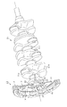
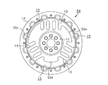
- FIG. 1 Front view of the flexible flywheel. Partially enlarged view in FIG. A perspective view showing a state in which a flexible flywheel is attached to a crankshaft.
- the front view which shows another example of a flexible flywheel.
- the front view which shows another example of a flexible flywheel.
- the front view which shows another example of a flexible flywheel.
- the front view which shows another example of a flexible flywheel.
- the flexible flywheel 10 has a circular shape as a whole.
- the flexible flywheel 10 has a shaft fastening portion 11, an inertia ring 12, an elastic spoke portion 13, and a weight portion 14.
- the shaft fastening portion 11, the inertia ring 12, the elastic spoke portion 13, and the weight portion 14 are castings made of cast iron or the like, and are integrally formed by casting.
- the shaft fastening portion 11 is fastened to the tip end portion of the crankshaft 21.
- the shaft fastening portion 11 is formed in a disk shape and is provided in the central portion of the flexible flywheel 10. As shown in FIG. 3, the shaft fastening portion 11 comes into contact with the end surface 23 of the fastened portion 22 provided at the end portion of the crankshaft 21 when the shaft fastening portion 11 is attached to the crankshaft 21.
- a positioning hole 31 is provided in the central portion of the shaft fastening portion 11.
- the tip protrusion 24 provided on the end surface 23 is inserted into the positioning hole 31 as shown in FIG.
- the rotation center axis of the crankshaft 21 and the rotation center axis of the flexible flywheel 10 are positioned to be the same.
- a plurality of bolt insertion holes 32 are provided around the positioning hole 31 so as to form an annular shape.
- a bolt hole 25 corresponding to the bolt insertion hole 32 is provided in the fastened portion 22 of the crankshaft 21. With the tip protrusion 24 of the crankshaft 21 inserted into the positioning hole 31, the positions of the bolt insertion hole 32 and the bolt hole 25 are aligned. By screwing the bolt 26 into the bolt hole 25, the shaft fastening portion 11 is fastened to the fastened portion 22. As a result, the flexible flywheel 10 is fixed to the crankshaft 21.
- the inertia ring 12 is formed in an annular shape.
- the inertia ring 12 becomes an inertial mass, and a relatively large inertial force moment is obtained by its weight.
- a screw hole 33 is formed in the inertia ring 12.
- a damper (not shown) is attached using the screw hole 33. The presence or absence of a damper is optional.
- the elastic spoke portion 13 extends along the radial direction of the flexible flywheel 10 between the shaft fastening portion 11 and the inertia ring 12 and connects the two. As shown in FIG. 2, the elastic spoke portion 13 is formed to be wide. In the elastic spoke portion 13, the side edge 34a of the outer connecting portion 34 with the inertia ring 12 is formed so as to form a radius shape that is concave inward.
- the elastic spoke portion 13 is formed to be thinner than the shaft fastening portion 11.
- the vibration damping effect is obtained by the bending of the elastic spoke portion 13, and the flywheel is made flexible.
- the thickness of the elastic spoke portion 13 is arbitrary, but is set to, for example, 2 mm to 5 mm. Therefore, the surface rigidity of the elastic spoke portion 13 is lowered as compared with the plate portion of the flywheel which is not intended to obtain the vibration damping effect, and the elastic spoke portion 13 is easily bent.
- three elastic spoke portions 13 are provided, and all have the same configuration.
- the three elastic spoke portions 13 are evenly arranged in the circumferential direction of the flexible flywheel 10.
- the virtual lines L1 to L3 connecting the center of each elastic spoke portion 13 in the width direction and the center of the flexible flywheel 10 are assumed.
- the angle between the virtual lines L1 to L3 is set to 120 degrees.
- Three space portions 15 are formed between the elastic spoke portions 13.
- Each elongated hole 35 is a through hole, and all are formed with the same shape and the same dimensions.
- the elongated hole 35 extends along the direction in which the elastic spoke portion 13 extends.
- one end on the shaft fastening portion 11 side is arranged near the shaft fastening portion 11, and the other end on the inertia ring 12 side is arranged near the inertia ring 12.
- the inner edges 36 at both ends thereof are all formed in a rounded shape.
- the elastic spoke portions 13 are formed with two elongated holes 35, the elastic spoke portions 13 are divided into three fine spoke portions 13a to 13c.
- the central thin spoke portions 13b of the fine spoke portions 13a to 13c are provided on the above-mentioned virtual lines L1 to L3 passing through the left and right centers of the elastic spoke portions 13, and are in the same direction as the direction in which the elastic spoke portions 13 extend. Extends along.
- the thin spoke portions 13a and 13c on both sides are provided side by side in parallel with the central thin spoke portions 13b.
- the weight portions 14 are provided in all of the three space portions 15 provided between the elastic spoke portions 13. One weight portion 14 is provided in each space portion 15, and each of the weight portions 14 has the same configuration.
- the weight portion 14 is connected to the shaft fastening portion 11.
- the weight portion 14 is not connected to the inertia ring 12, and is provided apart from the inertia ring 12.
- An elastic spoke portion 13 is provided on the opposite side of the weight portion 14 with the shaft fastening portion 11 interposed therebetween.
- the weight portion 14 is provided on an extension line of the central thin spoke portion 13b.
- the weight portion 14 is formed in a flat plate shape and has the same plate thickness as the elastic spoke portions 13. Further, as shown in FIG. 1, the weight portion 14 is formed to be wide along the circumferential direction of the inertia ring 12 in the front view.
- the weight portion 14 has line symmetry with respect to an extension line extending from each of the above-mentioned virtual lines L1 to L3 passing through the center of the elastic spoke portion 13.
- the weight portion 14 is connected to the shaft fastening portion 11 in a wide range in the circumferential direction.
- the outer edge 37 of the weight portion 14 is formed so as to form an arc shape having the same curvature as the inertia ring 12.
- the side edge portions 38 on both sides of the weight portion 14 in the circumferential direction are formed so as to form an S shape.
- the weight connecting portion 41 which is a connecting portion of the weight portion 14 to the shaft fastening portion 11, and the inner connecting portion 42, which is a connecting portion of the elastic spoke portion 13 to the shaft fastening portion 11, are connected by a connecting portion 43.
- the connecting portion 43 is formed so as to form a radius shape that is concave toward the center of the shaft fastening portion 11.
- the outer edge portion of the connecting portion 43 is a side edge on both sides in the circumferential direction of the weight connecting portion 41, and is also a side edge on both sides in the circumferential direction of the inner connecting portion 42.
- the flexible flywheel 10 having the above configuration is connected to the end of the crankshaft 21 as shown in FIG. FIG. 3 shows an example of the connected state.
- the crank pin 21a located closest to the flexible flywheel 10 is supported by the crank arm 21b.
- the flexible flywheel 10 cranks so that the direction in which the crank arm 21b extends and the direction in which the elastic spokes 13 extend coincide with each other in a state where the crank arm 21b protrudes from the crankshaft 21c in the 12 o'clock direction. It is attached to the shaft 21. It is assumed that the explosive vibration at the time when the crank arm 21b starts to rotate from the 12 o'clock position is the largest, and the flexible flywheel 10 is affected by this. Therefore, the above-mentioned connected state is adopted.
- the bolt insertion hole 32 of the shaft fastening portion 11 and the bolt hole 25 of the fastened portion 22 are arranged so as to enable such attachment.
- connection state between the crankshaft 21 and the flexible flywheel 10 may be changed.
- the largest explosive vibration occurs when the crank arm 21b starts to rotate from a position different from the 12 o'clock position.
- the flexible flywheel 10 may be attached to the crankshaft 21 so that the direction in which the elastic spoke portion 13 extends is aligned with the deviation of the angle so that the position is, for example, 10 o'clock or 2 o'clock.
- crankshaft 21 When the crankshaft 21 rotates, an inertial moment is generated by the inertia ring 12, and a stable rotational operation of the crankshaft 21 can be obtained.
- the crankshaft 21 vibrates due to the driving of the engine, the vibration is transmitted to the shaft fastening portion 11 of the flexible flywheel 10.
- the elastic spoke portion 13 When it is further transmitted to the elastic spoke portion 13, the elastic spoke portion 13 is elastically deformed, and the vibration is absorbed and reduced. As a result, the crankshaft 21 can be stably rotated while vibration is suppressed.
- the flexible flywheel 10 is attached to the crankshaft 21 so that when the crank arm 21b is arranged at the 12 o'clock position, the elastic spoke portion 13 extends along the same direction.
- the crank arm 21b gives the largest vibration to the flexible flywheel 10 when it starts to rotate from this position.
- the explosive vibration from the crank arm 21b is received by the elastic spoke portion 13 having rigidity instead of the space portion 15, and the vibration is absorbed by the elastic spoke portion 13.
- the effect of vibration damping is enhanced with respect to the explosive vibration, which is a large vibration among the vibrations acting from the crankshaft 21.
- a weight portion 14 is provided on the opposite side of each elastic spoke portion 13 across the shaft fastening portion 11 in the direction in which each elastic spoke portion 13 extends.
- the elastic spoke portion 13 of the flexible flywheel 10 is formed to be thin, and the surface rigidity is lowered so that the flexible flywheel 10 is easily bent.
- the vibration is absorbed by the bending of the elastic spoke portion 13.
- the vibration of the crankshaft 21 can be damped.
- the elastic disk is a separate part from the inertia ring, and both are fastened.
- the elastic spoke portion 13 is integrally formed by casting together with the shaft fastening portion 11 and the inertia ring 12. Therefore, the number of parts is one, and the fastening work for integrating a plurality of parts becomes unnecessary. As a result, the manufacturing cost can be reduced while maintaining the vibration damping function.
- the weight portion 14 is also integrally molded by casting together with the shaft fastening portion 11 and the like. Therefore, the presence of the weight portion 14 does not increase the number of parts or require new fastening work. As a result, the vibration damping effect can be enhanced while reducing the manufacturing cost without increasing the number of parts and the work process.
- the weight portions 14 are provided on the extension lines of the virtual lines L1 to L3 at the center in the width direction of each elastic spoke portion 13. Therefore, a shaft fastening portion 11 is provided between each elastic spoke portion 13 and each weight portion 14 on the virtual lines L1 to L3. Therefore, vibration absorption and suppression are performed on both sides of the crankshaft 21, and the effect of attenuating the vibration of the crankshaft 21 can be enhanced.
- the weight connecting portion 41 which is a connecting portion of the weight portion 14 to the shaft fastening portion 11, and the inner connecting portion 42, which is a connecting portion of the elastic spoke portion 13 to the shaft fastening portion 11, are connected by a connecting portion 43.
- the connecting portion 43 has a rounded shape.
- the side edges 34a on both sides in the circumferential direction also have a rounded shape.
- the connecting portion 43 Since the connecting portion 43 has a rounded shape, the side edge of the weight connecting portion 41 is constricted. Due to this constriction, the weight portion 14 tends to vibrate. Further, when the elastic spoke portion 13 and the weight portion 14 bend due to vibration absorption, stress is concentrated on the connecting portion 43 and the outer connecting portion 34. Therefore, there is a risk of cracks occurring in the portion due to the aged use of the flexible flywheel 10. In this respect, since the side edge portions 34a on both sides of the connecting portion 43 and the outer connecting portion 34 in the circumferential direction are formed in a rounded shape, the stress concentration is relaxed and the possibility of cracks occurring in the portion can be reduced.
- the elastic spoke portion 13 is formed with two elongated holes 35 extending along the extending direction thereof, and is divided into three fine spoke portions 13a to 13c. Therefore, the elastic spoke portion 13 is lighter than the configuration in which the circular through hole is formed or the elongated hole 35 is not formed in the first place, and the surface rigidity is further lowered. As a result, the elastic spoke portion 13 is more easily bent, and the effect of attenuating the vibration of the crankshaft 21 is enhanced.
- both ends in the direction in which the elastic spoke portions 13 extend are arranged in the vicinity of the shaft fastening portion 11 and the inertia ring 12, respectively.
- the inner edges 36 at both ends are formed so as to form a radius. Therefore, a plurality of portions having a rounded shape are provided inside each of the inner connecting portion 42 and the outer connecting portion 34 of the elastic spoke portion 13. As a result, the stress acting on the connecting portions 34 and 42 when the elastic spoke portions 13 are bent can be relaxed as compared with the configuration in which the portion having the rounded shape is not provided.
- the present invention is not limited to the flexible flywheel 10 of the above embodiment, and for example, the following configuration may be adopted.
- the weight portion 14 is provided on the extension line at the center of each elastic spoke portion 13 in the width direction (on the extension line of the virtual lines L1 to L3).
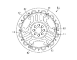
- a configuration in which the weight portion 14 is provided at a position deviated from the extension line at the center in the width direction of the elastic spoke portion 53 may be adopted as in the flexible flywheel 52 shown in FIG.
- the weight portions 14 are arranged at positions deviated from the extension line at the center in the width direction, the weight portions 14 are provided on both sides of the elastic spoke portions 53 in the circumferential direction as shown in FIG. 4, and the weight portions 14 on both sides thereof are provided. Is line-symmetrical with respect to the virtual line L4 passing through the center of the elastic spoke portion 53 in the width direction, and preferably has the same shape. As a result, as in the above embodiment, the vibration generated in the crankshaft 21 can be absorbed evenly on the left and right, and the vibration can be attenuated in a well-balanced manner.
- one weight portion 14 is provided in each space portion 15 between the elastic spoke portions 13.
- a plurality of weight portions 14 may be provided in each space portion 15, or a different number of weight portions 14 may be provided in each space portion 15. If a plurality of weight portions 14 are provided in one space portion 15, the plurality of weight portions 14 are arranged so as to be line-symmetric with respect to the extension lines of the virtual lines L1 to L3 on which the elastic spoke portions 13 extend. It is preferable to be done. Even with this configuration, the same effect as that of the above embodiment can be obtained.
- the thickness of the weight portion 14 is the same as the thickness of the elastic spoke portion 13.
- the thickness of the weight portion 14 may be formed to be thicker than the thickness of the elastic spoke portion 13.
- the three weight portions 14 do not have the same shape, size, weight, etc., but the weight portions 55a having different shapes, sizes, weights, etc., as in the flexible flywheel 54 shown in FIG. ⁇ 55c may be provided.
- the elongated holes 35 are formed in the elastic spoke portions 13. Instead of this, as in the elastic spoke portion 53 shown in FIG. 4, the elongated hole 35 may not be provided. Further, instead of the elongated hole 35, one or a plurality of through holes having a circular shape or an elliptical shape may be formed, or a teardrop-shaped through hole 57 may be formed as shown in FIG. 6, or the elongated hole 35 and another shape may be penetrated. It may be combined with a hole. Even if the elongated hole 35 is formed, it may be formed so as to extend in a direction intersecting the direction in which the elastic spoke portion 13 does not extend in the extending direction as in the above embodiment.
- the number of elongated holes 35 formed in the elastic spoke portion 13 is arbitrary, and for example, one elongated hole 35 may be formed, or three or more elongated holes 35 may be formed.
- the dimensions of the long hole 35 in the long axis or the short axis direction are also arbitrary.
- the dimensions of the short axis method may be longer or the dimensions in the long axis direction as compared with the long hole 35 of FIG. 1 in this embodiment. May be shorter.
- the elastic spoke portions 13 are divided into three fine spoke portions 13a to 13c by forming two elongated holes 35.
- Each of the fine spoke portions 13a to 13c extends along the radial direction in which the elastic spoke portions 13 extend.
- the fine spoke portions 58a to 58c of the elastic spoke portions 58 may be formed so as to form a radial pattern.
- three thin spoke portions 58a to 58c extending radially are provided, but the number thereof is arbitrary.
- the weight portion 14 is connected to the shaft fastening portion 11, is not connected to the inertia ring 12, and is provided apart from the inertia ring 12.
- the weight portion 62 is connected to the inertia ring 12, is not connected to the shaft fastening portion 11, and is provided apart from the shaft fastening portion 11. You may do so.
- the edge portion of the weight portion 62 on the side of the shaft fastening portion 11 is formed so as to form an arc shape, and the side edge portions at both ends in the circumferential direction are formed so as to form an S shape. Also in this configuration, when the crankshaft 21 vibrates, the vibration can be absorbed by the vibration of the weight portion 62, as in the above embodiment.
- the shaft fastening portion 11, the inertia ring 12, the elastic spoke portion 13, and the weight portion 14 are integrally molded by casting.
- a flexible flywheel in which all of these elements are integrally molded by forging may be used. Even with this configuration, the same effect as that of the above embodiment can be obtained.
- an internal combustion engine (engine) of a vehicle is assumed as a rotating machine.
- the scope of this disclosure is not limited to that. If it is used for the purpose of stabilizing the rotation using the moment of inertia, preserving the rotational energy, etc., it may be applied to, for example, a flywheel used in a press machine.
Landscapes
- Engineering & Computer Science (AREA)
- General Engineering & Computer Science (AREA)
- Physics & Mathematics (AREA)
- Acoustics & Sound (AREA)
- Aviation & Aerospace Engineering (AREA)
- Mechanical Engineering (AREA)
- Shafts, Cranks, Connecting Bars, And Related Bearings (AREA)
Abstract
L'invention concerne un volant flexible (10) équipé : d'une partie de fixation d'arbre (11) fixée à une partie d'extrémité d'un vilebrequin de moteur ; d'une bague d'inertie annulaire (12) disposée autour de la partie de fixation d'arbre (11) ; d'une pluralité de parties rayon élastiques (13) qui s'étendent dans la direction radiale entre la partie de fixation d'arbre (11) et la bague d'inertie (12) et fixent la partie de fixation d'arbre et la bague d'inertie l'une à l'autre, et qui absorbent les vibrations agissant sur le vilebrequin en subissant une déviation ; et de parties poids (14) disposées entre des parties rayon élastiques (13) adjacentes. La partie de fixation (11), la bague d'inertie (12), les parties rayon élastiques (13) et les parties poids (14) sont formées d'un seul tenant par moulage ou forgeage.
Priority Applications (4)
| Application Number | Priority Date | Filing Date | Title |
|---|---|---|---|
| US17/429,224 US11873879B2 (en) | 2019-03-25 | 2020-03-11 | Flexible flywheel |
| CN202080016951.1A CN113490801B (zh) | 2019-03-25 | 2020-03-11 | 挠性飞轮 |
| JP2021509003A JP7060760B2 (ja) | 2019-03-25 | 2020-03-11 | フレキシブルフライホイール |
| DE112020001446.0T DE112020001446T5 (de) | 2019-03-25 | 2020-03-11 | Flexibles schwungrad |
Applications Claiming Priority (2)
| Application Number | Priority Date | Filing Date | Title |
|---|---|---|---|
| JP2019056923 | 2019-03-25 | ||
| JP2019-056923 | 2019-03-25 |
Publications (1)
| Publication Number | Publication Date |
|---|---|
| WO2020195833A1 true WO2020195833A1 (fr) | 2020-10-01 |
Family
ID=72611396
Family Applications (1)
| Application Number | Title | Priority Date | Filing Date |
|---|---|---|---|
| PCT/JP2020/010544 Ceased WO2020195833A1 (fr) | 2019-03-25 | 2020-03-11 | Volant flexible |
Country Status (5)
| Country | Link |
|---|---|
| US (1) | US11873879B2 (fr) |
| JP (1) | JP7060760B2 (fr) |
| CN (1) | CN113490801B (fr) |
| DE (1) | DE112020001446T5 (fr) |
| WO (1) | WO2020195833A1 (fr) |
Cited By (2)
| Publication number | Priority date | Publication date | Assignee | Title |
|---|---|---|---|---|
| JP2025026598A (ja) * | 2021-09-29 | 2025-02-21 | アイシン高丘株式会社 | フレキシブルフライホイール |
| WO2025204128A1 (fr) * | 2024-03-28 | 2025-10-02 | Astemo株式会社 | Produit de coulée |
Families Citing this family (2)
| Publication number | Priority date | Publication date | Assignee | Title |
|---|---|---|---|---|
| JP7101711B2 (ja) * | 2020-02-19 | 2022-07-15 | アイシン高丘株式会社 | フレキシブルフライホイール |
| DE102022104006A1 (de) * | 2022-02-21 | 2023-08-24 | Schaeffler Technologies AG & Co. KG | Schwingungsdämpfer aufgebaut aus Speichenfedertilgern |
Citations (6)
| Publication number | Priority date | Publication date | Assignee | Title |
|---|---|---|---|---|
| JPS54109584A (en) * | 1978-02-15 | 1979-08-28 | Agency Of Ind Science & Technol | Energy accumulating fly-wheel with spoke |
| JPS5758542B2 (fr) * | 1976-09-07 | 1982-12-10 | Mitsubishi Motors Corp | |
| JPS60177350U (ja) * | 1984-05-04 | 1985-11-25 | 日産自動車株式会社 | 内燃機関のフライホイ−ル |
| JPH0712646U (ja) * | 1993-08-05 | 1995-03-03 | 本田技研工業株式会社 | フレキシブルフライホイール |
| JPH11182631A (ja) * | 1997-12-19 | 1999-07-06 | Daihatsu Motor Co Ltd | フレキシブルフライホイール |
| JP2004074230A (ja) * | 2002-08-19 | 2004-03-11 | Ricoh Co Ltd | フライホイールおよびその製造方法 |
Family Cites Families (31)
| Publication number | Priority date | Publication date | Assignee | Title |
|---|---|---|---|---|
| US670388A (en) * | 1900-07-05 | 1901-03-19 | George H Howard | Fly-wheel. |
| AT239612B (de) | 1962-10-29 | 1965-04-12 | Geislinger Dr Ing Leonard | Schwingungsdämpfer für Torsionsschwingungen |
| US3387505A (en) | 1965-10-23 | 1968-06-11 | Houdaille Industries Inc | Tuned torsional vibration damper |
| US3462136A (en) | 1967-06-29 | 1969-08-19 | Houdaille Industries Inc | Tuned viscous vibration dampers |
| JPH084735A (ja) * | 1994-06-21 | 1996-01-09 | Komatsu Forklift Co Ltd | 荷役車両におけるフライホイールと出力軸との連結構造 |
| KR960706033A (ko) | 1994-08-20 | 1996-11-08 | 알 모랄 | 트윈 매스 플라이휠 |
| JP3208016B2 (ja) | 1994-08-30 | 2001-09-10 | 富士機工株式会社 | 車両用ドライブプレート |
| JP3160165B2 (ja) * | 1994-09-30 | 2001-04-23 | 富士機工株式会社 | 車両用ドライブプレート |
| JP3556056B2 (ja) * | 1996-09-04 | 2004-08-18 | 株式会社エクセディ | フレキシブルプレート及びそれを使用したフライホイール組立体 |
| US6216327B1 (en) * | 1998-04-30 | 2001-04-17 | Simpson Industries, Inc. | Spoke centered puller tab crankshaft damper hub |
| US6440044B1 (en) * | 1998-08-07 | 2002-08-27 | Spiraflex, Inc. | Resistance mechanism with series connected resistance packs |
| JP3541716B2 (ja) * | 1999-03-11 | 2004-07-14 | 三菱自動車工業株式会社 | 内燃機関のフライホイール装置 |
| KR200199530Y1 (ko) * | 2000-03-30 | 2000-10-02 | 정인관 | 중심부에 밸런스 웨이트가 형성된 플라이 휘일 |
| FR2849683B1 (fr) * | 2003-01-06 | 2006-07-28 | Valeo Embrayages | Volant d'inertie flexible pour dispositif de transmission de couple |
| FR2880398B1 (fr) * | 2005-01-03 | 2007-02-16 | Valeo Embrayages | Volant d'inertie pour moteur a combustion interne |
| FR2890716B1 (fr) * | 2005-09-09 | 2007-12-07 | Valeo Embrayages | Volant d'inertie flexible, en particulier pour vehicule automobile |
| MX2010003958A (es) * | 2007-10-18 | 2010-04-27 | Kohler Co | Ensamblaje de volante. |
| FR2925638B1 (fr) * | 2007-12-20 | 2012-12-21 | Renault Sas | Volant d'inertie pour vehicule automobile avec joints amortissants |
| DE102011017397A1 (de) | 2010-05-14 | 2011-11-17 | Schaeffler Technologies Gmbh & Co. Kg | Schwungrad |
| JP5728186B2 (ja) * | 2010-09-13 | 2015-06-03 | アイシン機工株式会社 | ドライブプレートおよびドライブプレートのリングギヤ部材 |
| JP6265140B2 (ja) | 2012-12-21 | 2018-01-24 | 株式会社リコー | マイクロレンズアレイおよび移動体 |
| WO2017035515A1 (fr) | 2015-08-27 | 2017-03-02 | Dayco Ip Holdings, Llc | Amortisseurs de vibrations de torsion comprenant un moyeu avec des rayons agissant comme un second ressort en série avec un élément élastomère |
| US20170102048A1 (en) * | 2015-10-13 | 2017-04-13 | Ford Global Technologies, Llc | High performance flexplate with alternating radial wall thickness and multi-profile lightening holes |
| DE102016207100A1 (de) | 2016-04-27 | 2017-11-02 | Schaeffler Technologies AG & Co. KG | Schwingungsdämpfer |
| CN109210144B (zh) * | 2017-06-29 | 2022-12-09 | 南京法雷奥离合器有限公司 | 预加载部件,预加载组件,双质量飞轮和机动车辆 |
| CN108050204A (zh) * | 2018-01-06 | 2018-05-18 | 樊品良 | 一种飞轮联轴器 |
| CN108708934A (zh) * | 2018-08-01 | 2018-10-26 | 广西玉柴机器股份有限公司 | 二缸机轴系平衡减振系统 |
| CN109083979A (zh) * | 2018-08-28 | 2018-12-25 | 中国北方发动机研究所(天津) | 一种挠性组合飞轮 |
| IT201800010483A1 (it) * | 2018-11-21 | 2020-05-21 | Scuola Superiore Di Studi Univ E Di Perfezionamento Santanna | Molla torsionale planare |
| DE102019101983B4 (de) | 2019-01-28 | 2022-11-17 | Schaeffler Technologies AG & Co. KG | Speichenfedertilger und Verwendung eines Speichenfedertilgers |
| JP7101711B2 (ja) * | 2020-02-19 | 2022-07-15 | アイシン高丘株式会社 | フレキシブルフライホイール |
-
2020
- 2020-03-11 DE DE112020001446.0T patent/DE112020001446T5/de active Pending
- 2020-03-11 WO PCT/JP2020/010544 patent/WO2020195833A1/fr not_active Ceased
- 2020-03-11 US US17/429,224 patent/US11873879B2/en active Active
- 2020-03-11 JP JP2021509003A patent/JP7060760B2/ja active Active
- 2020-03-11 CN CN202080016951.1A patent/CN113490801B/zh active Active
Patent Citations (6)
| Publication number | Priority date | Publication date | Assignee | Title |
|---|---|---|---|---|
| JPS5758542B2 (fr) * | 1976-09-07 | 1982-12-10 | Mitsubishi Motors Corp | |
| JPS54109584A (en) * | 1978-02-15 | 1979-08-28 | Agency Of Ind Science & Technol | Energy accumulating fly-wheel with spoke |
| JPS60177350U (ja) * | 1984-05-04 | 1985-11-25 | 日産自動車株式会社 | 内燃機関のフライホイ−ル |
| JPH0712646U (ja) * | 1993-08-05 | 1995-03-03 | 本田技研工業株式会社 | フレキシブルフライホイール |
| JPH11182631A (ja) * | 1997-12-19 | 1999-07-06 | Daihatsu Motor Co Ltd | フレキシブルフライホイール |
| JP2004074230A (ja) * | 2002-08-19 | 2004-03-11 | Ricoh Co Ltd | フライホイールおよびその製造方法 |
Cited By (3)
| Publication number | Priority date | Publication date | Assignee | Title |
|---|---|---|---|---|
| JP2025026598A (ja) * | 2021-09-29 | 2025-02-21 | アイシン高丘株式会社 | フレキシブルフライホイール |
| JP7755033B2 (ja) | 2021-09-29 | 2025-10-15 | アイシン高丘株式会社 | フレキシブルフライホイール |
| WO2025204128A1 (fr) * | 2024-03-28 | 2025-10-02 | Astemo株式会社 | Produit de coulée |
Also Published As
| Publication number | Publication date |
|---|---|
| DE112020001446T5 (de) | 2021-12-02 |
| JPWO2020195833A1 (ja) | 2021-10-14 |
| US11873879B2 (en) | 2024-01-16 |
| CN113490801A (zh) | 2021-10-08 |
| JP7060760B2 (ja) | 2022-04-26 |
| US20220010859A1 (en) | 2022-01-13 |
| CN113490801B (zh) | 2022-12-20 |
Similar Documents
| Publication | Publication Date | Title |
|---|---|---|
| JP7060760B2 (ja) | フレキシブルフライホイール | |
| JP6811702B2 (ja) | トーショナルダンパ | |
| US8813604B2 (en) | Pendulum vibration absorber on a crankshaft | |
| CN104813063B (zh) | 离心振子式减振装置 | |
| US10113611B2 (en) | Torsional vibration damper and engine assembly including the same | |
| KR20050086957A (ko) | 토크 전달 장치용 플랙시블 플라이휠 | |
| CN100557265C (zh) | 内燃发动机用惯性飞轮 | |
| JPS58128546A (ja) | 直列4気筒エンジン用フライホイ−ル | |
| KR101787413B1 (ko) | 샤프트용 다이내믹 댐퍼 | |
| JP2008175344A (ja) | 回転軸に対するダイナミックダンパの取付構造及びダイナミックダンパ付き回転軸 | |
| WO2021166685A1 (fr) | Volant flexible | |
| JPS6338572B2 (fr) | ||
| JP7110829B2 (ja) | ダイナミックダンパ | |
| JP2006090528A (ja) | 回転軸用制振装置 | |
| JP3532612B2 (ja) | トーショナルダンパ | |
| JPH0543313Y2 (fr) | ||
| JP7420456B2 (ja) | 内燃機関のクランク軸 | |
| JPH0640992Y2 (ja) | エンジンのフライホイール装置 | |
| JP7067381B2 (ja) | ダンパー装置 | |
| JP2019148303A (ja) | ダイナミックダンパ | |
| JP2002139103A (ja) | クランクダンパ | |
| JP7208753B2 (ja) | プレート部材 | |
| JPH0539231Y2 (fr) | ||
| JPH024269Y2 (fr) | ||
| KR20180054313A (ko) | 듀얼 매스 플라이휠의 펜듈럼 조립체 |
Legal Events
| Date | Code | Title | Description |
|---|---|---|---|
| 121 | Ep: the epo has been informed by wipo that ep was designated in this application |
Ref document number: 20776618 Country of ref document: EP Kind code of ref document: A1 |
|
| ENP | Entry into the national phase |
Ref document number: 2021509003 Country of ref document: JP Kind code of ref document: A |
|
| 122 | Ep: pct application non-entry in european phase |
Ref document number: 20776618 Country of ref document: EP Kind code of ref document: A1 |