WO2020195890A1 - Système de déplacement automatique - Google Patents
Système de déplacement automatique Download PDFInfo
- Publication number
- WO2020195890A1 WO2020195890A1 PCT/JP2020/010794 JP2020010794W WO2020195890A1 WO 2020195890 A1 WO2020195890 A1 WO 2020195890A1 JP 2020010794 W JP2020010794 W JP 2020010794W WO 2020195890 A1 WO2020195890 A1 WO 2020195890A1
- Authority
- WO
- WIPO (PCT)
- Prior art keywords
- parallel
- rice transplanter
- reference line
- parallel path
- traveling
- Prior art date
- Legal status (The legal status is an assumption and is not a legal conclusion. Google has not performed a legal analysis and makes no representation as to the accuracy of the status listed.)
- Ceased
Links
Images


Classifications
-
- G—PHYSICS
- G05—CONTROLLING; REGULATING
- G05D—SYSTEMS FOR CONTROLLING OR REGULATING NON-ELECTRIC VARIABLES
- G05D1/00—Control of position, course, altitude or attitude of land, water, air or space vehicles, e.g. using automatic pilots
- G05D1/60—Intended control result
- G05D1/648—Performing a task within a working area or space, e.g. cleaning
-
- A—HUMAN NECESSITIES
- A01—AGRICULTURE; FORESTRY; ANIMAL HUSBANDRY; HUNTING; TRAPPING; FISHING
- A01B—SOIL WORKING IN AGRICULTURE OR FORESTRY; PARTS, DETAILS, OR ACCESSORIES OF AGRICULTURAL MACHINES OR IMPLEMENTS, IN GENERAL
- A01B69/00—Steering of agricultural machines or implements; Guiding agricultural machines or implements on a desired track
- A01B69/007—Steering or guiding of agricultural vehicles, e.g. steering of the tractor to keep the plough in the furrow
- A01B69/008—Steering or guiding of agricultural vehicles, e.g. steering of the tractor to keep the plough in the furrow automatic
-
- G—PHYSICS
- G05—CONTROLLING; REGULATING
- G05D—SYSTEMS FOR CONTROLLING OR REGULATING NON-ELECTRIC VARIABLES
- G05D1/00—Control of position, course, altitude or attitude of land, water, air or space vehicles, e.g. using automatic pilots
- G05D1/02—Control of position or course in two dimensions
- G05D1/021—Control of position or course in two dimensions specially adapted to land vehicles
- G05D1/0212—Control of position or course in two dimensions specially adapted to land vehicles with means for defining a desired trajectory
- G05D1/0219—Control of position or course in two dimensions specially adapted to land vehicles with means for defining a desired trajectory ensuring the processing of the whole working surface
-
- G—PHYSICS
- G05—CONTROLLING; REGULATING
- G05D—SYSTEMS FOR CONTROLLING OR REGULATING NON-ELECTRIC VARIABLES
- G05D1/00—Control of position, course, altitude or attitude of land, water, air or space vehicles, e.g. using automatic pilots
- G05D1/20—Control system inputs
- G05D1/24—Arrangements for determining position or orientation
- G05D1/247—Arrangements for determining position or orientation using signals provided by artificial sources external to the vehicle, e.g. navigation beacons
- G05D1/248—Arrangements for determining position or orientation using signals provided by artificial sources external to the vehicle, e.g. navigation beacons generated by satellites, e.g. GPS
-
- G—PHYSICS
- G05—CONTROLLING; REGULATING
- G05D—SYSTEMS FOR CONTROLLING OR REGULATING NON-ELECTRIC VARIABLES
- G05D1/00—Control of position, course, altitude or attitude of land, water, air or space vehicles, e.g. using automatic pilots
- G05D1/40—Control within particular dimensions
- G05D1/43—Control of position or course in two dimensions [2D]
-
- G—PHYSICS
- G05—CONTROLLING; REGULATING
- G05D—SYSTEMS FOR CONTROLLING OR REGULATING NON-ELECTRIC VARIABLES
- G05D2101/00—Details of software or hardware architectures used for the control of position
- G05D2101/10—Details of software or hardware architectures used for the control of position using artificial intelligence [AI] techniques
-
- G—PHYSICS
- G05—CONTROLLING; REGULATING
- G05D—SYSTEMS FOR CONTROLLING OR REGULATING NON-ELECTRIC VARIABLES
- G05D2105/00—Specific applications of the controlled vehicles
- G05D2105/15—Specific applications of the controlled vehicles for harvesting, sowing or mowing in agriculture or forestry
-
- G—PHYSICS
- G05—CONTROLLING; REGULATING
- G05D—SYSTEMS FOR CONTROLLING OR REGULATING NON-ELECTRIC VARIABLES
- G05D2107/00—Specific environments of the controlled vehicles
- G05D2107/20—Land use
- G05D2107/21—Farming, e.g. fields, pastures or barns
-
- G—PHYSICS
- G05—CONTROLLING; REGULATING
- G05D—SYSTEMS FOR CONTROLLING OR REGULATING NON-ELECTRIC VARIABLES
- G05D2109/00—Types of controlled vehicles
- G05D2109/10—Land vehicles
Definitions
- the present invention relates to an automatic traveling system that automatically travels a work vehicle along a target traveling route.
- the above-mentioned automatic driving system sets a reference line as a target traveling route and automatically advances the work vehicle along the reference line (see, for example, Patent Document 1).
- the reference line is set by operating a setting device or the like. Is going.
- a reference route based on the movement trajectory when the user or the like drives the work vehicle and actually drive the work vehicle, and generate a target travel route according to the reference route. It has been.
- a target traveling route including a plurality of parallel routes arranged in parallel with the reference route is generated.
- the main problem of the present invention is to provide an automatic driving system capable of reducing the workload of users and the like and improving work efficiency.
- the first feature configuration of the present invention includes a first reference line, a storage unit for storing a second reference line, and a storage unit.
- a traveling route generation unit that generates a parallel path parallel to the first reference line or the second reference line, and The point is that an automatic traveling control unit for automatically traveling the work vehicle along the parallel path generated by the traveling route generation unit is provided.
- the traveling route generation unit can generate not only the first reference line stored in the storage unit but also a parallel route parallel to the second reference line.
- the automatic traveling control unit can efficiently perform a predetermined work by automatically traveling the work vehicle not only along the parallel path parallel to the first reference line but also along the parallel path parallel to the second reference line.
- the user or the like does not have to newly perform the adjustment work or the manual operation of the work vehicle. Therefore, while reducing the work load on the user, the work vehicle is automatically driven not only along the parallel path parallel to the first reference line but also along the parallel path parallel to the second reference line to improve work efficiency. Can be planned.
- the traveling route generation unit selects one of the first reference line and the second reference line based on the position information of the work vehicle, and the traveling route generation unit selects the reference line of the work vehicle. It is at the point of generating the parallel path parallel to the selected reference line through the current position.
- the traveling route generation unit performs the first reference line and the second reference based on the position information of the work vehicle at that time.
- One of the reference lines of the line can be selected to generate a parallel path that passes through the current position of the work vehicle and is parallel to the selected reference line. Therefore, the user can automatically drive along the parallel route according to the work start point simply by moving the work vehicle to the work start point or the like, effectively reducing the work load of the user. , Automatic driving can be performed properly.
- the traveling route generation unit can generate a plurality of first parallel paths parallel to the first reference line at predetermined intervals as the parallel paths, and the work vehicle. The point is that a second parallel path that passes through the current position and is parallel to the second reference line can be generated.
- the traveling route generation unit can generate a plurality of first parallel routes having working widths at predetermined intervals, and can generate a second parallel route according to the current position of the work vehicle.
- a plurality of first parallel paths can be generated and a predetermined work can be performed by automatic traveling, while in the peripheral region around the central region, the shape of the work region and the like can be dealt with.
- automatic traveling can be performed while targeting the already generated first parallel path, and automatic traveling along the first parallel path is efficient. It can be done well and appropriately.
- the fourth characteristic configuration of the present invention is that the automatic traveling control unit can automatically travel the work vehicle on a plurality of the parallel paths, and moves from the parallel path to the next parallel path. Allows manual driving of the work vehicle. When the work vehicle is manually driven from the parallel path to the next parallel path, a notification suggesting a deviation between the position of the work vehicle after the end of the manual run and the start position of the automatic run on the next parallel path is sent. The point is that a notification control unit is provided.
- the notification control unit determines the position of the work vehicle after the manual travel is completed and the start position of the automatic travel in the next parallel route. Since the notification suggesting the deviation of the above is performed, it is possible to guide to the start position of the automatic traveling in the next parallel route. As a result, the automatic traveling along the next parallel route can be smoothly started, and the automatic traveling along the next parallel route can be efficiently and appropriately performed.
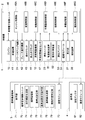
- the figure which shows the schematic structure of the automatic driving system Block diagram showing the schematic configuration of the autonomous driving system The figure which shows the operation when generating the target driving route Diagram showing the state of generating a target driving route Diagram showing the state of generating a target driving route
- the figure which shows the state which generated the target driving route and the state which performs automatic driving Flowchart showing the flow of operation when performing automatic driving
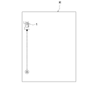
- the figure which shows the state which generated the target driving path in the work area, and the state which performs automatic driving The figure which shows the state which generates the 1st parallel path
- the figure which shows the state which generates the 2nd reference line The figure which shows the state which generated the 1st reference line and the 2nd reference line in a work area
- this automatic traveling system applies the rice transplanter 1 as a work vehicle, but other than the rice transplanter, a passenger work vehicle such as a tractor, a combine, a riding grass mowing machine, a wheel loader, and a snowplow, It can also be applied to unmanned work vehicles such as unmanned mowers.
- this automatic traveling system includes an automatic traveling unit 2 mounted on a rice transplanter 1 and a mobile communication terminal 3 set to communicate with the automatic traveling unit 2.
- a mobile communication terminal 3 As the mobile communication terminal 3, a tablet-type personal computer, a smartphone, or the like having a touch-operable touch panel type display unit 71 (for example, a liquid crystal panel) or the like can be adopted.
- the rice transplanter 1 is provided with a traveling machine 11 and a planting section 13 at the rear of the traveling machine 11 via an elevating drive mechanism 12.
- the traveling machine body 11 is provided with an engine 15 as a power source arranged in the front upper portion of a vehicle body frame 14 extending in the front-rear direction, and a bonnet 16 covering the engine 15.
- a front axle case 17 is supported on the front part of the vehicle body frame 14, and front wheels 18 are attached to both left and right sides of the front axle case 17.
- a rear axle case 19 is supported at the rear portion of the vehicle body frame 14, and rear wheels 20 are attached to both left and right sides of the rear axle case 19.
- a gate-shaped spare seedling stand frame 21 is erected from the vehicle body frame 14, and spare seedling stand 22 is arranged on both left and right sides of the spare seedling stand frame 21.
- the positioning unit 23 is arranged at the center of the upper left and right of the spare seedling mounting frame 21.
- the rear part of the bonnet 16 is provided with a steering wheel 25 that enables manual steering of the left and right front wheels 18 via the power steering mechanism 24, a driver's seat 26 for passengers, and the like.
- the dashboard at the rear of the bonnet 16 is provided with an operation panel type display unit 27 (see FIG. 2), a notification device 28 (see FIG. 2), and the like.
- the planting section 13 is provided with a seedling stand 29 on which a seedling mat is placed, and a plurality of rotary planting devices 30 for planting seedlings in a work place such as a field.
- the seedling stand 29 is provided so as to be movable in the left-right direction in an inclined posture in which the front side is high and the rear side is low.
- the number of planting devices 30 is provided according to the number of rows in the planting work. For example, in the case of 6-row planting, 6 planting devices 30 are provided.
- the planting device 30 is arranged at the rear of the planting transmission case 31.
- a strip stop clutch 44 (see FIG. 2) is provided for each of the plurality of planting devices 30, and the power transmission to each of the planting devices 30 is intermittently configured.
- markers 32 are provided to mark a work place such as a field as a guide for the work of the next process.
- the marker 32 is swingably provided at an action position where a mark is attached to the work place by projecting outward and a non-action position where the mark is retracted upward, and the marker 32 can be driven and operated between the action position and the non-action position.
- a marker operating mechanism 45 (see FIG. 2) is provided.
- the rice planting machine 1 operates an electronically controlled transmission 41 that shifts the power from the engine 15, a fully hydraulic power steering mechanism 24 that steers the left and right front wheels 18, and a braking device.
- In-vehicle electronic control having an electro-hydraulic control type elevating drive mechanism 12 for elevating and lowering, a marker operating mechanism 45 for driving and operating a marker 32 between an operating position and a non-acting position, and various control programs related to automatic traveling of the rice planting machine 1.
- the unit 46, a vehicle condition detection sensor 47 for detecting various vehicle conditions in the rice planting machine 1, and the like are provided.
- the transmission 41 a hydraulic mechanical continuously variable transmission (HMT), a hydrostatic continuously variable transmission (HST), a belt type continuously variable transmission, or the like can be adopted.
- HMT hydraulic mechanical continuously variable transmission
- HST hydrostatic continuously variable transmission
- a belt type continuously variable transmission or the like
- an electric power steering mechanism 24 or the like provided with an electric motor may be adopted.
- the vehicle state detection sensor 47 includes, for example, an engine rotation speed sensor that detects the rotation speed of the engine 15, a vehicle speed sensor that detects the vehicle speed of the rice planting machine 1, a steering angle sensor that detects the steering angle of the front wheels 18, and the like. There is.
- the vehicle-mounted electronic control unit 46 includes an engine control unit 46A that controls the operation of the engine 15, a shift control unit 46B that controls the operation of the transmission 41, and a braking control that controls the operation of the brake operation mechanism 42.
- the work device control unit 46D that controls the operation of work devices such as the unit 46C and the planting unit 13, and the steering control unit 46E that controls the operation of the power steering mechanism 24 according to the target steering angles of the left and right front wheels 18 during automatic driving. It also has a non-volatile vehicle-mounted storage unit 46F or the like that stores the generated target traveling path P (see, for example, FIG. 6) for automatic traveling.
- the positioning unit 23 measures the current position and the current orientation of the rice planting machine 1 by using GPS (Global Positioning System), which is an example of a satellite positioning system (NSS: Navigation Satellite System). It is equipped with a satellite navigation device 51, an inertial measurement unit (IMU: Inertial Measurement Unit) 52, etc. that has a 3-axis gyroscope, a 3-direction acceleration sensor, etc. to measure the posture and orientation of the rice planting machine 1.
- Positioning methods using GPS include DGPS (Differential GPS: relative positioning method) and RTK-GPS (Real Time Kinematic GPS: interference positioning method).
- RTK-GPS suitable for positioning of a moving body is adopted. Therefore, as shown in FIGS. 1 and 2, a reference station 4 that enables positioning by RTK-GPS is installed at a known position around a work area such as a field.
- the rice transplanter 1 and the reference station 4 have the positioning antennas 53 and 61 that receive the radio waves transmitted from the positioning satellite 50 (see FIG. 1), and the rice transplanter 1 and the reference station 4 respectively.
- Communication modules 54, 62 and the like that enable wireless communication of various information including positioning information (correction information) between the antennas are provided.
- the satellite navigation device 51 receives the positioning information obtained by the positioning antenna 53 on the rice planting machine side receiving the radio waves from the positioning satellite 50 and the positioning antenna 61 on the base station side receiving the radio waves from the positioning satellite 50. Based on the positioning information obtained (correction information for measuring the current position of the rice planting machine 1), the current position and the current orientation of the rice planting machine 1 can be measured with high accuracy.
- the positioning unit 23 is provided with the satellite navigation device 51 and the inertial measurement unit 52 to measure the current position, current azimuth, and attitude angle (yaw angle, roll angle, pitch angle) of the rice transplanter 1 with high accuracy. be able to.
- the mobile communication terminal 3 is positioned between the terminal electronic control unit 72 having various control programs for controlling the operation of the display unit 71 and the like, and the communication module 54 on the rice transplanter side.
- a communication module 73 or the like that enables wireless communication of various information including information is provided.
- the terminal electronic control unit 72 includes a travel route generation unit 74 that generates a target travel route P (for example, see FIG. 6) for automatically traveling the rice transplanter 1, and various input information and travel route generation input by the user. It has a non-volatile terminal storage unit 75 and the like that stores the target travel path P and the like generated by the unit 74.
- the method of generating the target travel route P by the travel route generation unit 74 will be described later.
- the target travel route P generated by the travel route generation unit 74 can be displayed on the display unit 71, and is stored in the terminal storage unit 75 as route information.
- the route information includes the azimuth angle of the target traveling route P, the set engine rotation speed, the target traveling speed, and the like set according to the traveling mode of the rice transplanter 1 on the target traveling route P.
- the terminal electronic control unit 72 transfers the route information from the mobile communication terminal 3 to the rice transplanter 1, thereby in-vehicle electronic control of the rice transplanter 1.
- the unit 46 can acquire the route information.
- the in-vehicle electronic control unit 46 automatically travels the rice transplanter 1 along the target travel route P while acquiring its own current position (current position of the rice transplanter 1) by the positioning unit 23 based on the acquired route information. Can be made to.
- the current position of the rice transplanter 1 acquired by the positioning unit 23 is transmitted from the rice transplanter 1 to the mobile communication terminal 3 in real time (for example, in a cycle of several milliseconds), and the rice transplanter 1 is transmitted by the mobile communication terminal 3. I know my current position.
- the in-vehicle electronic control unit 46 obtains its own current position (current position of the rice transplanter 1) by the positioning unit 23, and moves the rice transplanter 1 along the target traveling path P. Performs automatic driving control for automatic driving.
- the in-vehicle electronic control unit 46 automatically performs automatic traveling control for automatically traveling the rice transplanter 1 along the target traveling route P based on the positioning information of the rice transplanter 1 acquired by the positioning unit 23 using the satellite positioning system. It is configured as a travel control unit.
- the automatic driving control includes automatic engine control that automatically controls the operation of the engine 15, automatic shift control that automatically controls the operation of the transmission 41, braking control that automatically controls the operation of the brake operation mechanism 42, and automatic left and right front wheels 18. It includes automatic steering control for steering, automatic control for work that automatically controls the operation of a work device such as a planting unit 13, and the like.
- the engine control unit 46A automatically operates the engine 15 so that the rotation speed of the engine 15 becomes the set engine rotation speed based on the detection information of the engine rotation speed sensor in the vehicle state detection sensor 47. Control.
- the shift control unit 46B determines the rice transplanter 1 on the target travel path P based on the route information of the target travel path P, the output of the positioning unit 23, and the output of the vehicle speed sensor in the vehicle state detection sensor 47.
- the operation of the transmission 41 is automatically controlled so that the target traveling speed set according to the traveling mode and the like can be obtained as the vehicle speed of the rice transplanter 1.
- the braking control unit 46C operates the brake so as to properly brake in the braking region included in the route information of the target traveling path P based on the target traveling path P and the output of the positioning unit 23.
- the operation of the mechanism 42 is automatically controlled.
- the steering control unit 46E determines the target steering angle based on the route information of the target travel path P and the steering angle sensor in the vehicle state detection sensor 47 so that the rice planting machine 1 automatically travels on the target travel path P. Based on the output, the operation of the power steering mechanism 24 is automatically controlled so that the target steering angle is obtained as the steering angles of the left and right front wheels 18.
- the work device control unit 46D reaches the work start point of the target travel route P as the rice transplanter 1 reaches the work start point of the target travel route P based on the route information of the target travel route P and the output of the positioning unit 23.
- a predetermined work for example, planting work
- the work device such as the planting section 13 is used.
- the operation of the planting clutch 43, the streak clutch 44, the elevating drive mechanism 12, and the marker operating mechanism 45 is automatically controlled so that a predetermined operation is stopped.
- the automatic traveling unit 2 is composed of a vehicle state detection sensor 47, a positioning unit 23, a communication module 54, and the like.
- the travel route generation unit 74 In the work area R of the field or the like, the travel route generation unit 74 generates the target travel route P when the user or the like operates the rice transplanter 1 to actually perform the work.
- the mobile communication terminal 3 has a reference point setting unit 76 for setting the point A and the point B and an artificially operated reference point setting operation unit. 77 and is provided.
- FIG. 3 shows a case where the rice transplanter 1 is located at the point B.
- the reference point setting unit 76 sets the work start point as the point A and the work end point as the point B based on the operation of the reference point setting operation unit 77.
- the reference point setting operation unit 77 is displayed on the display unit 71 of the mobile communication terminal 3, for example, and includes an operation unit for the point A and an operation unit for the point B.
- the operation unit 77 for setting the reference point is prepared for the rice transplanter 1 (working vehicle). It is an operating tool that has been used.
- the reference point setting operation unit 77 is not limited to the one displayed on the display unit 71 of the mobile communication terminal 3, and various operation units can be applied. For example, it may be displayed on the display unit 27 of the rice transplanter 1, or may be an operation switch or an operation button arranged in the vicinity of the driver's seat 26 of the rice transplanter 1. Further, as will be described later, the remote controller 200 shown in FIG. 17 can be used as the reference point setting operation unit 77, and a user or the like boarding the rice transplanter 1 carries the reference point setting operation unit 77 (remote controller 200). You can also do it.
- the reference point setting unit 76 moves the positioning unit 23 at the time of the operation.
- the position information position information of the rice transplanter 1 is acquired, and the point A (the point determined from the latitude and longitude) is set in the work area R.
- the reference point setting unit 76 moves the positioning unit 23 at the time of the operation.
- a point B (a point determined from latitude and longitude) is set in the work area R based on the position information (position information of the rice transplanter 1).
- the reference point setting unit 76 acquires the position information of the rice transplanter 1 in the positioning unit 23 according to the operation timing of the reference point setting operation unit 77, and the point A and the point B, respectively. Is set.
- the reference point setting unit 76 stores the setting information of the point A and the point B in the terminal storage unit 75.
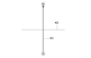
- the reference line generation unit 78 sets the reference point A and the point B based on the position information of the point A and the point B as shown in FIG. 1 reference line K1 and 2nd reference line K2 are generated.
- the reference line generation unit 78 generates a straight line connecting the point A and the point B as the first reference line K1, and generates a straight line orthogonal to the first reference line K1 as the second reference line K2.
- the reference line generation unit 78 stores the generated position information and the like of the first reference line K1 and the second reference line K2 in the terminal storage unit 75 (corresponding to the storage unit).
- the travel route generation unit 74 generates a route including the first parallel route P1 and the second parallel route P2 parallel to the first reference line K1 or the second reference line K2 as the target travel route P. are doing.
- the first parallel path P1 and the second parallel path P2 are routes for performing a predetermined work (planting work) while automatically traveling the rice transplanter 1.
- the traveling path generation unit 74 When starting the automatic running of the rice transplanter 1, after the predetermined conditions for starting the automatic running are satisfied, when the user operates the display unit 71 on the mobile communication terminal 3 to instruct the start of the automatic running, The automatic running of the rice transplanter 1 is started.
- the first parallel path P1 As shown in FIGS. 4 and 5, when the traveling path generation unit 74 generates the first reference line K1 by the reference line generation unit 78, the first parallel path P1 is set. It is generated, and the first parallel path P1 is generated in advance before the predetermined condition for starting automatic driving is satisfied.
- the second parallel path P2 As shown in FIGS. 4 and 5, the second parallel path P2 is generated when the first reference line K1 is generated by the reference line generation unit 78.
- the traveling route generation unit 74 generates the second parallel path P2 when the predetermined condition for starting the automatic traveling is satisfied, and the predetermined condition for starting the automatic traveling is satisfied. After that, the second parallel path P2 is generated.
- the traveling route generation unit 74 uses a path having the same or substantially the same length as the first reference line K1 as the first parallel path P1 and is the same as the first reference line K1.
- the set number of first parallel paths P1 (for example, 6 in FIGS. 5 and 6) is generated by setting the interval between the first parallel paths P1 and the intervals between the first parallel paths P1 as the set interval L1.
- the number of settings can be changed as appropriate, but if work area information related to the work area such as the size of the work area and the shape of the work area has not been acquired, the first parallel path P1 is generated outside the work area. As such, for example, 500 first parallel paths P1 are generated. Further, when the work area information is acquired, the set number can be set so as to fit within the work area.
- the traveling route generation unit 74 In generating the set number of first parallel paths P1, the traveling route generation unit 74 generates the first parallel paths P1 symmetrically with respect to the first reference line K1 as shown in FIGS. 5 and 6. ,
- the first reference line K1 can be positioned at the end to generate a set number of first parallel paths P1 on the right side or the left side of the first reference line K1.
- the setting interval L1 for example, the work interval based on the input information about the work device such as the planting unit 13 input by the user or the like is set as the setting interval L1.
- the interval between the rows for planting seedlings can be set to the set interval L1.
- the traveling path generation unit 74 generates a second parallel path P2 that passes through the current position of the rice transplanter 1 and is parallel to the second reference line K2.
- the traveling route generation unit 74 uses the current position of the rice transplanter 1 as the start position of the second parallel path P2, and the first parallel path P1 located at the most end of the set number of generated first parallel paths P1. (In FIG. 6, the position of the first parallel path P1 located on the leftmost side) is set as the terminal position of the second parallel path P2, and the second parallel path P2 is generated.
- connection route Q is a route for changing the traveling direction of the rice transplanter 1 without performing any work.
- the terminal electronic control unit 72 transfers the route information from the mobile communication terminal 3 to the rice transplanter 1, so that the vehicle-mounted electronic control unit 46 of the rice transplanter 1 transfers the route. I'm getting information.
- the in-vehicle electronic control unit 46 acquires its own current position (current position of the rice transplanter 1) by the positioning unit 23 based on the acquired route information, and the rice transplanter 1 is along the target traveling route P. Can be run automatically.
- the current position of the rice transplanter 1 acquired by the positioning unit 23 is transmitted from the rice transplanter 1 to the mobile communication terminal 3 in real time (for example, in a cycle of several milliseconds), and the rice transplanter 1 is transmitted by the mobile communication terminal 3.
- the deviation (lateral deviation) between the current position of the rice transplanter 1 and the target traveling route P in the direction orthogonal to the traveling direction of the target traveling route P is set to the mobile communication terminal 3.
- the rice transplanter 1 is driven by a user or the like to actually perform the work, and the reference point setting unit 76 registers (sets) the points A and B. (Step # 1, Step # 2).
- the reference line generation unit 78 generates the first reference line K1 and the second reference line K2 based on the setting information of the points A and B, and the traveling route generation unit 74 has a plurality of parallel to the first reference line K1.
- the first parallel path P1 of the above is generated (step # 3, step # 4).
- the terminal electronic control unit 72 satisfies the first predetermined condition that the orientation of the rice transplanter 1 in the traveling direction and the orientation of the first parallel path P1 in the extending direction are within a predetermined range, or the rice transplanter 1 travels. It is determined whether or not the second predetermined condition that the direction and the orientation of the extension direction of the second reference line K2 are within a predetermined range is satisfied (steps # 5 and # 6).
- the direction of the rice transplanter 1 in the traveling direction can be obtained from the measurement information of the positioning unit 23, and the direction of the extension direction of the reference line can be obtained from the positions of the first parallel path P1 and the second reference line K2. It can be obtained from the information.
- the vehicle is mounted on the vehicle.
- the electronic control unit 46 takes the rice transplanter 1 along the first parallel path P1 based on the positioning information of the rice transplanter 1 acquired by the positioning unit 23 using the satellite positioning system.
- the first automatic running is performed (in the case of Yes in step # 5, step # 8 in the case of Yes in step # 7). This first automatic traveling is performed on the first parallel path P1 that satisfies the first predetermined condition among the plurality of first parallel paths P1 generated in advance.
- the vehicle-mounted electronic control unit 46 starts the work (planting work) by the planting portion 13 at the start position P1a of the first parallel path P1, and the first parallel path P1.
- the rice transplanter 1 is automatically driven in a straight line along the first parallel path P1 in a form in which the work (planting work) by the planting portion 13 is completed at the terminal position P1b of the above.
- the traveling route generation unit 74 When the second predetermined condition is satisfied, the traveling route generation unit 74 generates the second parallel path P2 parallel to the second reference line K2 (in the case of Yes in step # 6, step # 9).
- the in-vehicle electronic control unit 46 positions the vehicle using a satellite positioning system as shown in the lower side of FIG. Based on the positioning information of the rice transplanter 1 acquired by the unit 23, the second automatic traveling is performed in which the rice transplanter 1 is automatically traveled along the second parallel path P2 (in the case of Yes in step # 10, step # 11). ..
- the in-vehicle electronic control unit 46 starts the work (planting work) by the planting unit 13, and performs the work (planting work) by the planting unit 13 at the terminal position P2a of the second parallel path P2.
- the rice transplanter 1 is automatically driven in a straight line along the second parallel path P2 in the form of ending. Since the rice transplanter 1 is manually operated when the work by the planting unit 13 is started, the work by the planting unit 13 can also be started by a manual operation by a user or the like.
- the rice transplanter 1 is automatically driven along the first parallel path P1 or the second parallel path P2 (steps # 5 to # 11). ), These operations are repeated until the work in the work area such as a field is completed (in the case of No in step # 12).
- the in-vehicle electronic control unit 46 determines that the work in the work area has been completed when the work end conditions such as the rice transplanter 1 being moved out of the work area are satisfied.
- the position of the rice transplanter 1 is set to the second predetermined condition by the user's manual operation. Every time the vehicle is moved to the established position, the second parallel path P2 is automatically driven.
- the terminal electronic control unit 72 sets the setting information of the points A and B stored in the terminal storage unit 75, the first reference line K1 and The information about the second reference line K2 is deleted. As a result, the points A and B in the next work area can be registered so that the first reference line K1 and the second reference line K2 can be generated.
- Various conditions can be set as the setting information erasing condition, for example, that the rice transplanter 1 has moved out of the work area, or that the set time has elapsed from the end of the automatic running.
- the rice transplanter 1 is automatically driven for the first parallel path P1 and the second parallel path P2, but the rice transplanter 1 is used for the connecting path Q for changing the traveling direction of the rice transplanter 1.
- the rice transplanter 1 is manually operated by the user's manual operation without automatic driving. Therefore, the in-vehicle electronic control unit 46 can automatically run the rice transplanter 1 on the plurality of first parallel paths P1 and the second parallel paths P2, and as shown in FIG. 6, the first parallel path. For the movement from P1 to the next first parallel path P1, the rice transplanter 1 is allowed to run manually.
- a notification control unit 46G (see FIG. 2) that performs deviation notification suggesting a deviation between the position and the start position of automatic traveling on the next first parallel path P1 is provided.
- the notification control unit 46G displays, for example, the current position of the rice transplanter 1 and the next first parallel path P1 on the display unit 27 of the rice transplanter 1, so that the user can display the current position of the rice transplanter 1.
- the deviation from the start position of the automatic running on the next first parallel path P1 can be recognized.
- the terminal electronic control unit 72 can also display the display unit 71 of the mobile communication terminal 3 so that the display unit 27 of the rice transplanter 1 superimposes the current position of the rice transplanter 1 and the next first parallel path P1.
- the rice transplanter 1 that is manually operated can be guided toward the start position P1a of the first parallel path P1.
- the display unit 27 of the rice transplanter 1 and the display unit 71 of the mobile communication terminal 3 are provided with a deviation information display unit having a plurality of display lamp units, and the notification control unit 46G and the terminal electronic control unit 72 serve as deviation notification.
- the lighting mode of the plurality of indicator lamps it is possible to display in which direction and how much the current position of the rice transplanter 1 is deviated from the start position P1a of the next first parallel path P1. it can.
- the indicator lamp portion located in the central portion of the plurality of indicator lamp portions is located. Turn on.
- the current position of the rice transplanter 1 is located on the right side of the start position P1a of the next first parallel path P1 beyond a predetermined range, it is located on the right side of the central portion among the plurality of indicator lamp portions. Turn on only the indicator lamp. At this time, as the amount of deviation to the right side increases, the number of display lamp units to be turned on in the form of lighting the indicator lamp unit located on the right side can be increased.
- the notification control unit 46G and the terminal electronic control unit 72 provide deviation notification that suggests a deviation between the current position of the rice transplanter 1 and the start position P1a of the next first parallel path P1 in any display form. Can be changed as appropriate. In addition, for example, it is possible to perform a deviation notification by voice such as "I am moving to the right side".
- the rice transplanter 1 During automatic driving, in order to prevent the rice transplanter 1 from jumping out of the work area, the rice transplanter 1 notifies the user and the like of the approaching state in which the rice transplanter 1 approaches the end of the work area. As shown in FIG. 2, based on the setting information of the points A and B, and the position information of the first parallel path P1, the notification for performing the end notification to notify that the work area is approaching the end.
- a notification position specifying unit 79 for specifying a position and a notification control unit 46G for performing end notification when the current position of the rice transplanter 1 reaches the notification position when the rice transplanter 1 automatically travels are provided. ..
- the notification position specifying unit 79 is provided in the mobile communication terminal 3. As shown in FIG. 6, the notification position specifying unit 79 specifies the terminal position P1b of the first parallel path P1 as the notification position for the first parallel path P1 based on the position information of the points A and B. .. Further, the notification position specifying unit 79 uses the terminal position P2a of the second parallel path P2 as the notification position based on the position information of the first parallel path P1 generated on the endmost side of the second parallel path P2. I have specified.
- the notification control unit 46G is acquired by the positioning unit 23 using the satellite positioning system in the automatic travel control for automatically traveling the rice transplanter 1.
- the notification position for example, the terminal position P1b or the terminal position P2a
- the notification device 28 is operated to notify the end. This is performed, and the user or the like is notified of the approaching state of approaching the end of the work area or the like.
- various notifications such as a voice indicating an approaching state, lighting of an alarm lamp, operation of an alarm buzzer, and the like can be performed by the notification device 28.
- the mobile communication terminal 3 is notified of the approaching state, such as displaying that the display unit 71 of the mobile communication terminal 3 is in the approaching state. can do.
- the in-vehicle electronic control unit 46 can also stop the rice transplanter 1 from running. By stopping the rice transplanter 1 in this way, it is possible to appropriately prevent the rice transplanter 1 from jumping out of the work area.
- the rice transplanter 1 can be automatically driven not only on the first parallel path P1 parallel to the first reference line K1 but also on the second parallel path P2 parallel to the second reference line K2.
- a predetermined work planting work
- the rice transplanter 1 is automatically driven over the entire work area R to improve work efficiency. be able to.
- a first parallel path P1 parallel to the first reference line K1 is generated to automatically run the rice transplanter 1
- the work area R is in the vertical direction.
- a second parallel path P2 parallel to the second reference line K2 is generated to automatically run the rice transplanter 1.
- the traveling route generation unit 74 generates not only a route having the same route length as the first reference line K1 but also an extended first parallel route P3 having a route length longer than that of the first reference line K1 as the first parallel route P1. are doing.
- the user operates the display unit 71 of the mobile communication terminal 3 during the automatic traveling or the manual operation of the first parallel path P1 to generate the traveling route generation unit.
- 74 extends the first parallel path P1 to the position of the rice transplanter 1 at the time of the operation to generate the extended first parallel path P3.
- it can be extended by a preset distance or by a distance set by a user or the like.
- the travel path generation unit 74 is not only a path having a path length as the second parallel path P2 from the current position of the rice transplanter 1 to the second parallel path P2 generated on the farthest end side, but also more than that.
- An extended second parallel path P4 with a long path length is generated.
- the extended second parallel path P4 is generated, for example, the user operates the display unit 71 of the mobile communication terminal 3 during the automatic traveling or the manual operation of the second parallel path P2 to generate the traveling route generation unit.
- 74 extends the second parallel path P2 to the position of the rice transplanter 1 at the time of the operation to generate the extended second parallel path P4.
- it can be extended by a preset distance or by a distance set by a user or the like.
- the traveling order of the route for automatically traveling the rice transplanter 1 is shown, and thus the traveling order will be described.
- (1) When the orientation of the rice transplanter 1 in the traveling direction and the orientation of the first parallel path P1 in the traveling order (1) in the extension direction are within a predetermined range and the first predetermined condition is satisfied, the in-vehicle electronic control unit 46 , The rice transplanter 1 is automatically driven along the first parallel path P1 in the traveling order (1).
- the connection route Q is traveled by the user's manual operation, and the orientation of the rice transplanter 1 in the traveling direction and the orientation of the first parallel path P1 in the traveling order (2) in the extension direction are within a predetermined range.
- the vehicle-mounted electronic control unit 46 automatically travels the rice transplanter 1 along the first parallel path P1 in the traveling order (2). Since (3) to (5) perform the same operations as (1) and (2), the description thereof will be omitted.
- the rice transplanter 1 After reaching the terminal position P1b of the first parallel path P1 in the traveling order (5), the rice transplanter 1 is switched to manual operation and the rice transplanter 1 is moved to the lower right side in the figure, and the rice transplanter 1 When the azimuth in the traveling direction and the azimuth in the extension direction of the second reference line K2 are within a predetermined range and the second predetermined condition is satisfied, the extended second parallel path P4 of (6) is generated. Then, the in-vehicle electronic control unit 46 automatically runs the rice transplanter 1 along the extension second parallel path P4 of (6).
- Extension of traveling order (6) After reaching the terminal position P4a of the second parallel path P4, the rice transplanter 1 is switched to manual operation and the rice transplanter 1 is moved to the upper side in the drawing, and the rice transplanter 1 travels.
- the in-vehicle electronic control unit 46 moves to the first traveling order (7). 2
- the rice transplanter 1 is automatically driven along the parallel path P2.
- the second parallel path P2 is extended from the initial terminal position P2a to generate the extended second parallel path P4, and the second parallel path P4 is automatically traveled along the extended second parallel path P4.
- the traveling route generation unit 74 sets the distance L2 between the first reference line K1 and the first parallel path P1 and the distance L2 between the adjacent first parallel paths P1 between the points B and C. It can be set based on the distance. That is, the traveling route generation unit 74 sets the distance L2 between the first reference line K1 and the first parallel path P1 and the distance L2 between the adjacent first parallel paths P1 to be the same as the distance between the points B and C. Can be set to.
- the second reference line K2 is a straight line orthogonal to the first reference line K1, but the second reference line K2 is orthogonal to the first reference line K1.
- the straight line is not limited to the straight line, and may be a straight line having a predetermined intersection angle with the first reference line K1.
- the reference line generation unit 78 sets the straight line connecting the point B and the point C as the second reference line K2. Can be generated.
- the reference point S for the entrance / exit corresponding to the entrance / exit R1 of the work area R can be registered.
- the reference point S for the entrance / exit is registered, and then the point A and the point B are registered.
- the reference line generation unit 78 can generate a straight line connecting the reference point S for the entrance / exit and the point A which is the start point of the work as the second reference line K2.
- the second reference line K2 can be made a straight line according to the shape of the end portion of the work area R, and efficient work can be performed according to the shape of the work area R.
- the distance between the first reference line K1 and the first parallel path P1 and the distance between adjacent first parallel paths P1 will be described.
- a predetermined work planting work
- the power to the planting device 30 is supplied by the strip clutch 44 according to the condition of the work area such as the width of the work area.
- the planting work may be performed only by a part of the planting devices 30 among the plurality of planting devices 30.
- the traveling path generation unit 74 is connected to the first parallel path P1 (the second parallel path P1 from the right in the figure) in which the planting work is performed in the state where the strips are stopped.
- the distance from the first parallel path P1 (the first parallel path P1 on the far right in the figure) is changed to a distance L3 smaller than the distance L1 between the other adjacent first parallel paths P1.
- the traveling path generation unit 74 approaches the next first parallel path P1 with respect to the first parallel path P1 currently traveling. It is translated to the side by a predetermined distance.
- the predetermined distance can be set according to the number of the planting devices 30 with the strips, and the predetermined distance is set so as to increase the number of the planting devices 30 with the strips. ..
- the strip stop clutch 44 By the way, by detecting the operating state of the strip stop clutch 44, it is possible to determine whether or not the planting work is being performed with the strip stop applied.
- the travel path generation unit 74 can operate the display unit 71 of the mobile communication terminal 3 before the automatic travel is performed. All of the plurality of first parallel paths P1 can be translated by a predetermined distance.
- the state before the plurality of first parallel paths P1 are translated is shown on the left side, and the state after the plurality of first parallel paths P1 are translated is shown on the right side.
- the first parallel path P1 shown on the right side the first parallel path P1 before the parallel movement is shown by a dotted line, and the first parallel path P1 after the parallel movement is shown by a solid line so that you can see how the parallel movement was performed. Is shown.
- the user in a state where the position of the rice transplanter 1 is moved to a position laterally deviated from the first parallel path P1 during automatic traveling, the user can use the display unit 71 of the mobile communication terminal 3.
- the traveling route generation unit 74 can move the first parallel path P1 in parallel so that the current position of the rice transplanter 1 and the first parallel path P1 match.
- the first parallel path P1 before the translation is shown by a dotted line
- the first parallel path P1 after the translation is shown by a alternate long and short dash line.
- This second embodiment shows another embodiment of the first embodiment, and the configuration different from that of the first embodiment will be mainly described, and the same reference numerals will be given to the same configurations as those of the first embodiment. The description is omitted.
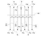
- the traveling route generation unit 74 uses either the first reference line K1 or the second reference line K2 based on the position information of the rice transplanter 1. A reference line is selected, and parallel paths P5 and P6 that pass through the current position of the rice transplanter 1 and are parallel to the selected reference line are generated.
- the reference line generation unit 78 is set to the first.
- a reference line K1 and a second reference line K2 are generated.
- the traveling route generation unit 74 determines whether or not a predetermined condition for starting automatic traveling is satisfied.
- the predetermined condition is the direction in which the rice transplanter 1 travels and the direction in which the reference line is extended (the direction in which the first reference line K1 is extended or the direction in which the second reference line K2 is extended). It is set to the inner condition.
- the direction of the rice transplanter 1 in the traveling direction can be obtained from the measurement information of the positioning unit 23, and the direction of the extension direction of the reference line can be obtained from the positions of the first reference line K1 and the second reference line K2. It can be obtained from the information.
- the traveling route generation unit 74 When the azimuth in the traveling direction of the rice transplanter 1 and the azimuth in the extension direction of the first reference line K1 are within a predetermined range and the first predetermined condition is satisfied, the traveling route generation unit 74 is shown by a dotted line in FIG. A first parallel path P5 that passes through the current position of the rice transplanter 1 and is parallel to the first reference line K1 is generated.
- the first parallel path P5 has a path length with the current position of the rice transplanter 1 as the start position and the position corresponding to the point A or the point B as the end position.
- the in-vehicle electronic control unit 46 enters the first parallel path P5 based on the positioning information of the rice transplanter 1 acquired by the positioning unit 23 using the satellite positioning system.
- the first automatic running is performed so that the rice transplanter 1 is automatically run along the line.
- the traveling route generation unit 74 When the azimuth in the traveling direction of the rice transplanter 1 and the azimuth in the extension direction of the second reference line K2 are within a predetermined range and the second predetermined condition is satisfied, the traveling route generation unit 74 has a solid line in FIG. A second parallel path P6 that passes through the current position of the rice transplanter 1 and is parallel to the second reference line K2 is generated.
- the second parallel path P6 has the current position of the rice transplanter 1 as the starting position and has a path length of only the set distance.
- the set distance can be set as appropriate, and can be changed and set by the user, for example.
- the in-vehicle electronic control unit 46 enters the second parallel path P6 based on the positioning information of the rice transplanter 1 acquired by the positioning unit 23 using the satellite positioning system.
- a second automatic running is performed in which the rice transplanter 1 is automatically run along the line.
- the first parallel path P5 or the second parallel path P6 is generated, and the generated first parallel path P5 or the second parallel path is generated.
- the rice transplanter 1 is automatically driven along P6.
- the timing of generating the first parallel path P5 is different from that of the first embodiment.
- the first reference path is formed after the first reference line K1 and the second reference line K2 are generated and at the timing before the first predetermined condition or the second predetermined condition is satisfied. Is being generated.
- the first parallel path P5 is generated at the timing after the first predetermined condition is satisfied. That is, in FIG. 7, step # 4 of "first parallel route generation" is changed between step # 5 of "whether the first predetermined condition is satisfied?" And step # 7 of "automatic driving start?"
- step # 4 of "first parallel route generation" is changed between step # 5 of "whether the first predetermined condition is satisfied?"
- other operations are the same as the operation flow shown in the flowchart of FIG. 7.
- This third embodiment shows another embodiment of the first embodiment, and the configuration different from that of the first embodiment will be mainly described, and the same reference numerals will be given to the same configurations as those of the first embodiment. The description is omitted.
- the remote controller 200 is provided in addition to or in place of the mobile communication terminal 3, as shown in FIG.
- a traveling route generation unit 74, a reference point setting unit 76, a reference line generation unit 78, a notification position identification unit 79, etc. Is provided in the in-vehicle electronic control unit 46.
- the vehicle-mounted storage unit 46F corresponds to the storage unit. Become.
- a remote controller 200 that can be carried by a user or the like is provided as a reference point setting operation unit 77.
- the remote controller 200 is configured to freely communicate various information with the in-vehicle electronic control unit 46 of the rice transplanter 1 via communication modules 54, 205 and the like.
- the remote controller 200 is instructed to automatically travel the operation unit 201 for the point A for registering the point A, the operation unit 202 for the point B for registering the point B, and the remote controller 200.
- a circular operation unit 203 for AUTO is provided for this purpose.
- a ring-shaped display unit 204 having light emitting parts such as a plurality of LEDs is provided around the circular operation unit 203 for AUTO, and the display unit 204 makes the lighting states of the plurality of light emitting parts different. , It is configured to be freely switchable to a plurality of display forms.
- the reference point setting unit 76 sets the point A and the point B
- the operation target operated by the user is the remote controller 200. Therefore, when the operation unit 201 for the point A of the remote controller 200 is operated, the reference point setting unit 76 acquires the position information (position information of the rice transplanter 1) of the positioning unit 23 at the time of the operation, and the point. A (point determined by latitude and longitude) is set. Further, when the operation unit 202 for the point B of the remote controller 200 is operated, the reference point setting unit 76 acquires the position information of the positioning unit 23 (position information of the rice transplanter 1) at the time of the operation, and the point. B (point determined by latitude and longitude) is set.
- the rice transplanter 1 is automatically run on the first parallel path P1 and the second parallel path P2, but the rice transplanter 1 Regarding the connection path Q for changing the traveling direction of the rice transplanter 1, the rice transplanter 1 is manually operated by the user's manual operation without automatically traveling the rice transplanter 1. Therefore, when the rice transplanter 1 is manually driven from the first parallel path P1 to the next first parallel path P1 (when the rice transplanter 1 is manually operated to travel on the connecting path Q), the rice transplanter after the manual traveling is completed. Deviation notification is performed that suggests a deviation between the position 1 and the start position of automatic traveling on the next first parallel path P1.
- the deviation notification is performed using the display unit 27 of the rice transplanter 1 and the display unit 71 of the mobile communication terminal 3, but in the third embodiment, the remote controller 200 is provided. Therefore, the deviation notification using the remote controller 200 will be described.
- the remote controller 200 is provided with a display control unit 206 that controls the display form of the display unit 204.
- the display control unit 206 controls the lighting state of a plurality of light emitting units in the display unit 204 as a deviation notification, so that the deviation between the current position of the rice transplanter 1 and the start position position P1a of the next first parallel path P1. It suggests.
- a plurality of light emitting units are shown in gray in FIG. Of these, only the light emitting part located in the center is turned on.
- the user can recognize how much the current position of the rice transplanter 1 is deviated from the start position P1a of the next first parallel path P1 in which direction. Moreover, when the current position of the rice transplanter 1 is located on the left side of the starting end position P1a of the next first parallel path P1 beyond a predetermined range, it is positioned on the center portion and the right side of the ring-shaped display unit 204. Since only the light emitting unit is lit, the user can easily recognize the direction in which the steering wheel 25 is operated, and can smoothly guide the user to the starting position P1a of the next first parallel path P1.
- the configuration of the work vehicle can be changed in various ways.
- the work vehicle may be configured to have a hybrid specification including an engine 15 and an electric motor for traveling, or may be configured to have an electric specification including an electric motor for traveling instead of the engine 15. .
- the work vehicle may be configured with rear wheel steering specifications in which the left and right rear wheels 20 function as steering wheels.
- the mobile communication terminal 3 is provided with a travel route generation unit 74, a reference point setting unit 76, a reference line generation unit 78, a notification position identification unit 79, and the like.
- the rice transplanter 1 may be provided with the generation unit 74, the reference point setting unit 76, the reference line generation unit 78, the notification position identification unit 79, and the like, or may be provided in an external management device, and the arrangement location can be changed as appropriate.
- the traveling route generation unit 74 does not generate the connecting route Q and does not automatically travel the rice transplanter 1 on the connecting route Q, but the traveling route generating unit 74 does not generate the connecting route Q. Is generated and stored in the terminal storage unit 75 or the like, so that the in-vehicle electronic control unit 46 can automatically drive the rice transplanter 1 along the connection path Q.
- the in-vehicle electronic control unit 46 can automatically drive the rice transplanter 1 along the connection path Q.
- the automatic traveling of the connecting route Q can be performed, and then the automatic traveling of the next first parallel path P1 can be performed. Therefore, the rice transplanter 1 can be automatically driven continuously on the plurality of first parallel paths P1 and the plurality of connected paths Q.
Landscapes
- Engineering & Computer Science (AREA)
- Life Sciences & Earth Sciences (AREA)
- Automation & Control Theory (AREA)
- Remote Sensing (AREA)
- Physics & Mathematics (AREA)
- General Physics & Mathematics (AREA)
- Radar, Positioning & Navigation (AREA)
- Aviation & Aerospace Engineering (AREA)
- Mechanical Engineering (AREA)
- Soil Sciences (AREA)
- Environmental Sciences (AREA)
- Guiding Agricultural Machines (AREA)
- Control Of Position, Course, Altitude, Or Attitude Of Moving Bodies (AREA)
- Harvester Elements (AREA)
Abstract
La présente invention comprend : une unité de stockage qui stocke une première ligne de référence (K1) et une seconde ligne de référence (K2) ; une unité de génération de trajet de déplacement qui génère des trajets parallèles (P1, P2), chacun desquels est parallèle à la première ligne de référence (K1) ou à la seconde ligne de référence (K2) ; et une unité de commande de déplacement automatique qui amène un véhicule de travail (1) à se déplacer automatiquement le long des trajets parallèles (P1, P2) générés par l'unité de génération de trajet de déplacement.
Priority Applications (5)
| Application Number | Priority Date | Filing Date | Title |
|---|---|---|---|
| KR1020267001005A KR20260019640A (ko) | 2019-03-25 | 2020-03-12 | 자동주행 시스템 |
| EP20779448.8A EP3951542B1 (fr) | 2019-03-25 | 2020-03-12 | Système de déplacement automatique |
| KR1020217021222A KR102913597B1 (ko) | 2019-03-25 | 2020-03-12 | 자동주행 시스템 |
| CN202080008733.3A CN113574486A (zh) | 2019-03-25 | 2020-03-12 | 自动行驶系统 |
| US17/598,221 US12329051B2 (en) | 2019-03-25 | 2020-03-12 | Automatic travel system |
Applications Claiming Priority (2)
| Application Number | Priority Date | Filing Date | Title |
|---|---|---|---|
| JP2019-056329 | 2019-03-25 | ||
| JP2019056329A JP7203654B2 (ja) | 2019-03-25 | 2019-03-25 | 自動走行システム |
Publications (1)
| Publication Number | Publication Date |
|---|---|
| WO2020195890A1 true WO2020195890A1 (fr) | 2020-10-01 |
Family
ID=72610497
Family Applications (1)
| Application Number | Title | Priority Date | Filing Date |
|---|---|---|---|
| PCT/JP2020/010794 Ceased WO2020195890A1 (fr) | 2019-03-25 | 2020-03-12 | Système de déplacement automatique |
Country Status (7)
| Country | Link |
|---|---|
| US (1) | US12329051B2 (fr) |
| EP (1) | EP3951542B1 (fr) |
| JP (4) | JP7203654B2 (fr) |
| KR (2) | KR102913597B1 (fr) |
| CN (1) | CN113574486A (fr) |
| TW (2) | TWI894924B (fr) |
| WO (1) | WO2020195890A1 (fr) |
Families Citing this family (10)
| Publication number | Priority date | Publication date | Assignee | Title |
|---|---|---|---|---|
| JP7352005B2 (ja) * | 2020-02-27 | 2023-09-27 | 本田技研工業株式会社 | 制御装置、作業機および作業システム |
| US12078996B2 (en) * | 2020-06-30 | 2024-09-03 | Cnh Industrial America Llc | System and method for implementing end-of-row turns for agricultural machines |
| JP7542388B2 (ja) * | 2020-10-02 | 2024-08-30 | 株式会社クボタ | 農作業機 |
| JP7447922B2 (ja) * | 2021-03-22 | 2024-03-12 | 株式会社リコー | 表示システム、通信システム、表示制御方法およびプログラム |
| JP7667008B2 (ja) * | 2021-07-21 | 2025-04-22 | ヤンマーホールディングス株式会社 | 走行制御方法、走行制御システム、及び走行制御プログラム |
| CN114249078A (zh) * | 2021-12-10 | 2022-03-29 | 广东智源机器人科技有限公司 | 轨道标识定位方法 |
| JP7681530B2 (ja) * | 2022-01-07 | 2025-05-22 | ヤンマーホールディングス株式会社 | 基準線設定方法、作業車両及び自動走行システム |
| JP7711026B2 (ja) * | 2022-03-31 | 2025-07-22 | ヤンマーホールディングス株式会社 | 経路生成方法、経路生成システム、及び経路生成プログラム |
| CN114818905B (zh) * | 2022-04-21 | 2024-07-26 | 福州大学 | 一种基于基站切换数据的车速估计误差的评价方法及系统 |
| CN121420737A (zh) * | 2025-12-30 | 2026-01-30 | 四川省农业科学院遥感与数字农业研究所(成都农业遥感分中心) | 不规则水田秧爪独立控制方法、作业规划方法及系统 |
Citations (6)
| Publication number | Priority date | Publication date | Assignee | Title |
|---|---|---|---|---|
| JPH0217011U (fr) | 1988-07-18 | 1990-02-02 | ||
| WO2015119263A1 (fr) * | 2014-02-06 | 2015-08-13 | ヤンマー株式会社 | Procédé de définition de trajet de déplacement de véhicule de travail à déplacement autonome |
| JP2015181371A (ja) * | 2014-03-20 | 2015-10-22 | ヤンマー株式会社 | 走行型収穫機 |
| JP2018099113A (ja) * | 2016-12-19 | 2018-06-28 | 株式会社クボタ | 走行経路決定装置 |
| JP2018117558A (ja) * | 2017-01-24 | 2018-08-02 | 株式会社クボタ | 作業車 |
| JP2019004816A (ja) * | 2017-06-27 | 2019-01-17 | 株式会社クボタ | 走行経路設定システム及び作業車 |
Family Cites Families (20)
| Publication number | Priority date | Publication date | Assignee | Title |
|---|---|---|---|---|
| JPH0217011A (ja) | 1988-07-05 | 1990-01-22 | Kokuyo Co Ltd | 卓上収納具兼用電話台 |
| JP3001701B2 (ja) | 1991-12-25 | 2000-01-24 | 本田技研工業株式会社 | 移動体の操向制御装置 |
| JPH07281743A (ja) * | 1994-04-04 | 1995-10-27 | Kubota Corp | 対地作業用作業車の走行方法及び走行制御設備 |
| JP2004275468A (ja) * | 2003-03-17 | 2004-10-07 | Hitachi Home & Life Solutions Inc | 自走式掃除機およびその運転方法 |
| GB201223363D0 (en) * | 2012-12-24 | 2013-02-06 | Agco Int Gmbh | Path planning method for agricultural vehicle guidance |
| WO2015132928A1 (fr) | 2014-03-06 | 2015-09-11 | ジオサーフ株式会社 | Système de guidage de champ, procédé de guidage de champ, logiciel, et support d'informations stockant le logiciel |
| JP6320212B2 (ja) | 2014-07-17 | 2018-05-09 | 株式会社クボタ | 走行作業機及びそれに用いられる自動操舵システム |
| JP6253538B2 (ja) * | 2014-07-17 | 2017-12-27 | 株式会社クボタ | 作業車 |
| CN119631665A (zh) * | 2015-12-25 | 2025-03-18 | 株式会社久保田 | 作业车 |
| JP6525902B2 (ja) | 2016-03-03 | 2019-06-05 | 株式会社クボタ | 圃場作業車両 |
| WO2017159801A1 (fr) * | 2016-03-18 | 2017-09-21 | ヤンマー株式会社 | Système de déplacement autonome |
| JP6945279B2 (ja) | 2016-06-28 | 2021-10-06 | 株式会社クボタ | 作業車 |
| JP2018073050A (ja) | 2016-10-27 | 2018-05-10 | 株式会社クボタ | 走行経路生成装置 |
| EP3557360B1 (fr) * | 2016-12-19 | 2022-08-03 | Kubota Corporation | Système de déplacement automatique d'engin de chantier |
| JP6812247B2 (ja) | 2017-01-20 | 2021-01-13 | 株式会社クボタ | 走行経路生成装置及び走行経路生成プログラム |
| JP6887256B2 (ja) | 2017-01-20 | 2021-06-16 | 株式会社クボタ | 走行経路生成装置 |
| JP6846998B2 (ja) | 2017-06-28 | 2021-03-24 | 株式会社クボタ | 作業車 |
| JP6908510B2 (ja) * | 2017-12-07 | 2021-07-28 | ヤンマーパワーテクノロジー株式会社 | 走行経路設定装置 |
| CN108919792B (zh) * | 2018-05-30 | 2021-08-24 | 华南农业大学 | 一种自动导航系统路径规划控制方法 |
| JP7236887B2 (ja) | 2019-03-14 | 2023-03-10 | ヤンマーパワーテクノロジー株式会社 | 経路生成システム |
-
2019
- 2019-03-25 JP JP2019056329A patent/JP7203654B2/ja active Active
-
2020
- 2020-03-12 KR KR1020217021222A patent/KR102913597B1/ko active Active
- 2020-03-12 US US17/598,221 patent/US12329051B2/en active Active
- 2020-03-12 EP EP20779448.8A patent/EP3951542B1/fr active Active
- 2020-03-12 WO PCT/JP2020/010794 patent/WO2020195890A1/fr not_active Ceased
- 2020-03-12 KR KR1020267001005A patent/KR20260019640A/ko active Pending
- 2020-03-12 CN CN202080008733.3A patent/CN113574486A/zh active Pending
- 2020-03-16 TW TW113114869A patent/TWI894924B/zh active
- 2020-03-16 TW TW109108567A patent/TWI843822B/zh active
-
2022
- 2022-09-21 JP JP2022150000A patent/JP7445721B2/ja active Active
-
2024
- 2024-02-26 JP JP2024026103A patent/JP7714708B2/ja active Active
-
2025
- 2025-07-16 JP JP2025119552A patent/JP2025142050A/ja active Pending
Patent Citations (6)
| Publication number | Priority date | Publication date | Assignee | Title |
|---|---|---|---|---|
| JPH0217011U (fr) | 1988-07-18 | 1990-02-02 | ||
| WO2015119263A1 (fr) * | 2014-02-06 | 2015-08-13 | ヤンマー株式会社 | Procédé de définition de trajet de déplacement de véhicule de travail à déplacement autonome |
| JP2015181371A (ja) * | 2014-03-20 | 2015-10-22 | ヤンマー株式会社 | 走行型収穫機 |
| JP2018099113A (ja) * | 2016-12-19 | 2018-06-28 | 株式会社クボタ | 走行経路決定装置 |
| JP2018117558A (ja) * | 2017-01-24 | 2018-08-02 | 株式会社クボタ | 作業車 |
| JP2019004816A (ja) * | 2017-06-27 | 2019-01-17 | 株式会社クボタ | 走行経路設定システム及び作業車 |
Also Published As
| Publication number | Publication date |
|---|---|
| KR102913597B1 (ko) | 2026-01-16 |
| JP2024045757A (ja) | 2024-04-02 |
| EP3951542A4 (fr) | 2022-11-16 |
| JP7445721B2 (ja) | 2024-03-07 |
| KR20260019640A (ko) | 2026-02-10 |
| JP7714708B2 (ja) | 2025-07-29 |
| TWI894924B (zh) | 2025-08-21 |
| TW202039285A (zh) | 2020-11-01 |
| CN113574486A (zh) | 2021-10-29 |
| US12329051B2 (en) | 2025-06-17 |
| EP3951542A1 (fr) | 2022-02-09 |
| KR20210145720A (ko) | 2021-12-02 |
| TWI843822B (zh) | 2024-06-01 |
| JP2025142050A (ja) | 2025-09-29 |
| EP3951542B1 (fr) | 2024-12-18 |
| JP7203654B2 (ja) | 2023-01-13 |
| JP2020156329A (ja) | 2020-10-01 |
| US20220183211A1 (en) | 2022-06-16 |
| TW202430406A (zh) | 2024-08-01 |
| JP2022171922A (ja) | 2022-11-11 |
Similar Documents
| Publication | Publication Date | Title |
|---|---|---|
| JP7445721B2 (ja) | 自動走行システム | |
| EP3473070B1 (fr) | Système de génération de trajet de déplacement de champ et véhicule de travail de champ | |
| US20220110239A1 (en) | Traveling Route Setting Device | |
| JP6749256B2 (ja) | 作業車の位置計測装置 | |
| JP2023067907A (ja) | 経路生成システム及び経路生成方法 | |
| JP6832884B2 (ja) | 自動走行システム及び状況報知装置 | |
| JP2021073602A (ja) | 自動走行システム及び状況報知装置 | |
| KR20170081685A (ko) | 농업용 작업차 | |
| JP7223552B2 (ja) | 表示装置、及び、自動走行システム | |
| JP7529627B2 (ja) | 走行速度制御装置 | |
| JP2022028334A (ja) | 自動走行システム | |
| JP2020095566A (ja) | 走行経路生成装置 | |
| JP7229119B2 (ja) | 自動走行システム | |
| JP7038651B2 (ja) | 圃場作業機及び農作業支援システム |
Legal Events
| Date | Code | Title | Description |
|---|---|---|---|
| 121 | Ep: the epo has been informed by wipo that ep was designated in this application |
Ref document number: 20779448 Country of ref document: EP Kind code of ref document: A1 |
|
| NENP | Non-entry into the national phase |
Ref country code: DE |
|
| ENP | Entry into the national phase |
Ref document number: 2020779448 Country of ref document: EP Effective date: 20211025 |
|
| WWG | Wipo information: grant in national office |
Ref document number: 17598221 Country of ref document: US |