WO2020195933A1 - Dispositif, procédé et programme de traitement d'informations - Google Patents
Dispositif, procédé et programme de traitement d'informations Download PDFInfo
- Publication number
- WO2020195933A1 WO2020195933A1 PCT/JP2020/011053 JP2020011053W WO2020195933A1 WO 2020195933 A1 WO2020195933 A1 WO 2020195933A1 JP 2020011053 W JP2020011053 W JP 2020011053W WO 2020195933 A1 WO2020195933 A1 WO 2020195933A1
- Authority
- WO
- WIPO (PCT)
- Prior art keywords
- information
- vehicle
- imaging
- unit
- flying object
- Prior art date
- Legal status (The legal status is an assumption and is not a legal conclusion. Google has not performed a legal analysis and makes no representation as to the accuracy of the status listed.)
- Ceased
Links
Images


Classifications
-
- G—PHYSICS
- G05—CONTROLLING; REGULATING
- G05D—SYSTEMS FOR CONTROLLING OR REGULATING NON-ELECTRIC VARIABLES
- G05D1/00—Control of position, course, altitude or attitude of land, water, air or space vehicles, e.g. using automatic pilots
- G05D1/10—Simultaneous control of position or course in three dimensions
- G05D1/101—Simultaneous control of position or course in three dimensions specially adapted for aircraft
- G05D1/102—Simultaneous control of position or course in three dimensions specially adapted for aircraft specially adapted for vertical take-off of aircraft
-
- B—PERFORMING OPERATIONS; TRANSPORTING
- B64—AIRCRAFT; AVIATION; COSMONAUTICS
- B64U—UNMANNED AERIAL VEHICLES [UAV]; EQUIPMENT THEREFOR
- B64U70/00—Launching, take-off or landing arrangements
- B64U70/90—Launching from or landing on platforms
-
- B—PERFORMING OPERATIONS; TRANSPORTING
- B64—AIRCRAFT; AVIATION; COSMONAUTICS
- B64U—UNMANNED AERIAL VEHICLES [UAV]; EQUIPMENT THEREFOR
- B64U80/00—Transport or storage specially adapted for UAVs
- B64U80/80—Transport or storage specially adapted for UAVs by vehicles
- B64U80/86—Land vehicles
-
- G—PHYSICS
- G05—CONTROLLING; REGULATING
- G05D—SYSTEMS FOR CONTROLLING OR REGULATING NON-ELECTRIC VARIABLES
- G05D1/00—Control of position, course, altitude or attitude of land, water, air or space vehicles, e.g. using automatic pilots
- G05D1/0011—Control of position, course, altitude or attitude of land, water, air or space vehicles, e.g. using automatic pilots associated with a remote control arrangement
-
- G—PHYSICS
- G05—CONTROLLING; REGULATING
- G05D—SYSTEMS FOR CONTROLLING OR REGULATING NON-ELECTRIC VARIABLES
- G05D1/00—Control of position, course, altitude or attitude of land, water, air or space vehicles, e.g. using automatic pilots
- G05D1/0094—Control of position, course, altitude or attitude of land, water, air or space vehicles, e.g. using automatic pilots involving pointing a payload, e.g. camera, weapon, sensor, towards a fixed or moving target
-
- G—PHYSICS
- G05—CONTROLLING; REGULATING
- G05D—SYSTEMS FOR CONTROLLING OR REGULATING NON-ELECTRIC VARIABLES
- G05D1/00—Control of position, course, altitude or attitude of land, water, air or space vehicles, e.g. using automatic pilots
- G05D1/10—Simultaneous control of position or course in three dimensions
- G05D1/101—Simultaneous control of position or course in three dimensions specially adapted for aircraft
-
- G—PHYSICS
- G05—CONTROLLING; REGULATING
- G05D—SYSTEMS FOR CONTROLLING OR REGULATING NON-ELECTRIC VARIABLES
- G05D1/00—Control of position, course, altitude or attitude of land, water, air or space vehicles, e.g. using automatic pilots
- G05D1/20—Control system inputs
- G05D1/22—Command input arrangements
- G05D1/221—Remote-control arrangements
- G05D1/227—Handing over between remote control and on-board control; Handing over between remote control arrangements
-
- G—PHYSICS
- G05—CONTROLLING; REGULATING
- G05D—SYSTEMS FOR CONTROLLING OR REGULATING NON-ELECTRIC VARIABLES
- G05D1/00—Control of position, course, altitude or attitude of land, water, air or space vehicles, e.g. using automatic pilots
- G05D1/40—Control within particular dimensions
- G05D1/46—Control of position or course in three dimensions [3D]
-
- G—PHYSICS
- G05—CONTROLLING; REGULATING
- G05D—SYSTEMS FOR CONTROLLING OR REGULATING NON-ELECTRIC VARIABLES
- G05D1/00—Control of position, course, altitude or attitude of land, water, air or space vehicles, e.g. using automatic pilots
- G05D1/60—Intended control result
- G05D1/656—Interaction with payloads or external entities
- G05D1/689—Pointing payloads towards fixed or moving targets
-
- G—PHYSICS
- G08—SIGNALLING
- G08G—TRAFFIC CONTROL SYSTEMS
- G08G5/00—Traffic control systems for aircraft
- G08G5/20—Arrangements for acquiring, generating, sharing or displaying traffic information
- G08G5/22—Arrangements for acquiring, generating, sharing or displaying traffic information located on the ground
-
- G—PHYSICS
- G08—SIGNALLING
- G08G—TRAFFIC CONTROL SYSTEMS
- G08G5/00—Traffic control systems for aircraft
- G08G5/20—Arrangements for acquiring, generating, sharing or displaying traffic information
- G08G5/26—Transmission of traffic-related information between aircraft and ground stations
-
- G—PHYSICS
- G08—SIGNALLING
- G08G—TRAFFIC CONTROL SYSTEMS
- G08G5/00—Traffic control systems for aircraft
- G08G5/50—Navigation or guidance aids
- G08G5/55—Navigation or guidance aids for a single aircraft
-
- H—ELECTRICITY
- H04—ELECTRIC COMMUNICATION TECHNIQUE
- H04N—PICTORIAL COMMUNICATION, e.g. TELEVISION
- H04N23/00—Cameras or camera modules comprising electronic image sensors; Control thereof
- H04N23/60—Control of cameras or camera modules
- H04N23/66—Remote control of cameras or camera parts, e.g. by remote control devices
- H04N23/661—Transmitting camera control signals through networks, e.g. control via the Internet
-
- H—ELECTRICITY
- H04—ELECTRIC COMMUNICATION TECHNIQUE
- H04N—PICTORIAL COMMUNICATION, e.g. TELEVISION
- H04N23/00—Cameras or camera modules comprising electronic image sensors; Control thereof
- H04N23/60—Control of cameras or camera modules
- H04N23/695—Control of camera direction for changing a field of view, e.g. pan, tilt or based on tracking of objects
-
- H—ELECTRICITY
- H04—ELECTRIC COMMUNICATION TECHNIQUE
- H04N—PICTORIAL COMMUNICATION, e.g. TELEVISION
- H04N7/00—Television systems
- H04N7/18—Closed-circuit television [CCTV] systems, i.e. systems in which the video signal is not broadcast
-
- H—ELECTRICITY
- H04—ELECTRIC COMMUNICATION TECHNIQUE
- H04N—PICTORIAL COMMUNICATION, e.g. TELEVISION
- H04N7/00—Television systems
- H04N7/18—Closed-circuit television [CCTV] systems, i.e. systems in which the video signal is not broadcast
- H04N7/183—Closed-circuit television [CCTV] systems, i.e. systems in which the video signal is not broadcast for receiving images from a single remote source
- H04N7/185—Closed-circuit television [CCTV] systems, i.e. systems in which the video signal is not broadcast for receiving images from a single remote source from a mobile camera, e.g. for remote control
-
- B—PERFORMING OPERATIONS; TRANSPORTING
- B64—AIRCRAFT; AVIATION; COSMONAUTICS
- B64U—UNMANNED AERIAL VEHICLES [UAV]; EQUIPMENT THEREFOR
- B64U10/00—Type of UAV
- B64U10/60—Tethered aircraft
-
- B—PERFORMING OPERATIONS; TRANSPORTING
- B64—AIRCRAFT; AVIATION; COSMONAUTICS
- B64U—UNMANNED AERIAL VEHICLES [UAV]; EQUIPMENT THEREFOR
- B64U2101/00—UAVs specially adapted for particular uses or applications
- B64U2101/30—UAVs specially adapted for particular uses or applications for imaging, photography or videography
-
- B—PERFORMING OPERATIONS; TRANSPORTING
- B64—AIRCRAFT; AVIATION; COSMONAUTICS
- B64U—UNMANNED AERIAL VEHICLES [UAV]; EQUIPMENT THEREFOR
- B64U2201/00—UAVs characterised by their flight controls
- B64U2201/10—UAVs characterised by their flight controls autonomous, i.e. by navigating independently from ground or air stations, e.g. by using inertial navigation systems [INS]
-
- B—PERFORMING OPERATIONS; TRANSPORTING
- B64—AIRCRAFT; AVIATION; COSMONAUTICS
- B64U—UNMANNED AERIAL VEHICLES [UAV]; EQUIPMENT THEREFOR
- B64U2201/00—UAVs characterised by their flight controls
- B64U2201/20—Remote controls
-
- G—PHYSICS
- G08—SIGNALLING
- G08G—TRAFFIC CONTROL SYSTEMS
- G08G5/00—Traffic control systems for aircraft
- G08G5/50—Navigation or guidance aids
- G08G5/57—Navigation or guidance aids for unmanned aircraft
-
- G—PHYSICS
- G08—SIGNALLING
- G08G—TRAFFIC CONTROL SYSTEMS
- G08G5/00—Traffic control systems for aircraft
- G08G5/50—Navigation or guidance aids
- G08G5/58—Navigation or guidance aids for emergency situations, e.g. hijacking or bird strikes
Definitions
- the present disclosure relates to information processing devices and methods, and programs, and in particular, to information processing devices, methods, and programs that enable easier imaging according to more diverse situations.
- the present disclosure has been made in view of such a situation, and makes it easier for the imaging device to perform imaging according to a wider variety of situations.
- the information processing device on one aspect of the present technology is an information processing device including a control unit that controls the image pickup device based on vehicle information, which is information about the vehicle.
- the information processing method of one aspect of the present technology is an information processing method that controls the image pickup device based on the vehicle information which is the information about the vehicle.
- the program of one aspect of the present technology is a program that causes a computer to function as a control unit that controls an image pickup device based on vehicle information, which is information about a vehicle.
- the image pickup device is controlled based on the vehicle information which is the information about the vehicle.
- First Embodiment> ⁇ Image control based on vehicle information>
- various systems utilizing an air vehicle such as a so-called drone have been studied. For example, a method of flying an air vehicle in a parking lot and guiding the user to a specific position has been considered.
- a patrol car may be equipped with a flying object having an imaging device, and the flying object may be flown during patrol to take an image from the sky, and the captured image may be used for recording and guidance. It was difficult to fly the flying object and take an image while it was running. In addition, there are situations where imaging is necessary and situations during patrol, and imaging is not necessary unless during patrol, but it is difficult to identify each situation and perform imaging in an appropriate situation. there were. Also, depending on the situation, there are cases where police officers should be imaged, cases where the area around the police car should be imaged, etc., but it is difficult to properly determine what is the subject and how to image it. It was. For example, it is conceivable that the operator manually operates the flying object or the imaging device depending on the situation, but in that case, complicated work is required.
- the imaging device including the imaging function unit and the imaging range variable unit is controlled based on the vehicle information which is the information about the vehicle.
- the information processing device is provided with a control unit that controls the image pickup device based on vehicle information, which is information about the vehicle.
- a program causes the computer to function as a control unit that controls an image pickup device based on vehicle information, which is information about the vehicle. By doing so, it is possible to more easily perform imaging according to various situations.
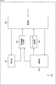
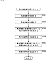
- FIG. 1 is a block diagram showing an example of a main configuration of a patrol support system, which is an aspect of an information processing system to which the present technology is applied.
- the patrol support system 100 shown in FIG. 1 is a system that supports patrol of police officers by taking an image and using the obtained image.
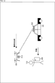
- the patrol support system 100 includes a patrol car 101, a base station 102, an air vehicle 103, a terminal device 104, and a central control server 105.
- the patrol car 101 is a vehicle on which the police officer 113 rides, and the police officer 113 performs operations such as driving. In addition to having a function as a normal vehicle, the patrol car 101 also has equipment peculiar to police vehicles such as a rotating light (also referred to as a red light or a light bar) and a wireless communication device. Further, the patrol car 101 includes a base station 102.
- the base station 102 is a control device that controls the flying object 103, and is a device that serves as an airfield for the flying object 103.
- the base station 102 and the air vehicle 103 are connected to each other by a cable 111 in order to physically limit the flight range of the air vehicle 103.
- the base station 102 has a communication function and can communicate with other devices such as a patrol car 101, an air vehicle 103, a terminal device 104, or a central control server 105.
- These communication methods are arbitrary, and may be wireless communication, wired communication, or both.
- the base station 102 and the air vehicle 103 may perform communication via the cable 111 (wired communication), or may perform wireless communication without the cable 111.
- the base station 102 may be able to wind the cable 111 so that the cable 111 does not loosen. In other words, the length of the cable 111 may be variable, and the flight restriction range of the flying object 103 may be variable.
- Aircraft 103 is an unmanned aerial vehicle such as a so-called drone.
- the aircraft body 103 uses the base station 102 as a takeoff and landing ground, and flies within the flight restriction range by the cable 111.
- the flying object 103 can fly autonomously or can fly (remotely controlled) under the control of another device such as the base station 102.
- the flying object 103 is provided with a camera 112 and has an imaging function.
- the flying object 103 can take an image while flying by using the camera 112 (imaging function unit). That is, the flying object 103 is an imaging range variable unit that makes the imaging range of the camera 112 variable (controls the imaging range). This imaging can be performed autonomously or can be controlled by another device such as the base station 102.
- the flying object 103 images the surroundings of the patrol car 101, police officer 113, etc. during patrol while flying.
- the captured image can be used for any purpose.
- this captured image may be used for controlling any other device such as the patrol car 101, the flying object 103, and the terminal device 104. Further, for example, the captured image may be used to support patrol activities such as recording and guidance.
- the camera 112 includes a flying object 103 and has a flight function. That is, the flying object 103 and the camera 112 can be said to be an aircraft (aircraft) having an imaging function unit and an imaging range variable unit, and can also be said to be an imaging device including an imaging function unit and an imaging range variable unit.
- the terminal device 104 is an electronic device carried by a police officer 113 who is a user (driver, crew member) of the patrol car 101.
- the terminal device 104 may be a portable terminal device such as a smartphone or a tablet device.
- the terminal device 104 may be a wearable device such as a wristwatch type, an eyeglass type, a ring type, a shoe type, a pocket type, or a pendant type.
- the terminal device 104 has an imaging function such as a camera, and can image a subject.
- the police officer 113 on patrol basically carries this terminal device 104, and the terminal device 104 images the situation around the police officer 113. This captured image can be used for any purpose. For example, this captured image may be used for controlling any other device such as a patrol car 101 or an air vehicle 103.
- the terminal device 104 may be provided with an arbitrary sensor so that information regarding the police officer 113 can be detected.
- the terminal device 104 may enable the sensor to detect the use of weapons and tools by the police officer 113, and the biological information of the police officer 113 such as pulse, heart rate, and line-of-sight direction.
- This detected information can be used for any purpose.
- this sensor information may be used to control any other device such as a patrol car 101 or an air vehicle 103.
- the central control server 105 is a server that manages the patrol support system 100.
- the patrol car 101 to the terminal device 104 described above are devices (local devices) on the terminal side in the patrol support system 100.
- the central control server 105 is a server-side device, and manages or controls, for example, the patrol car 101 to the terminal device 104.
- the configuration of the central control server 105 is arbitrary, and may be, for example, an information processing device provided in a central management facility such as a control center, or an information processing device whose configuration is not specified such as a so-called cloud server.
- the central control server 105 is communicably connected to the base station 102 via the network 114, communicates with the base station 102, controls the base station 102, acquires information from the base station 102, and obtains information from the base station 102. Communicates with other devices via.
- the central control server 105 is communicably connected to the patrol car 101, the flying object 103, and the terminal device 104 via the network 114, and can communicate with those devices without going through the base station 102. You may do so.
- the method (standard) of this communication is arbitrary, and may be wireless communication, wired communication, or both.
- the network 114 is an arbitrary network such as the Internet or a local area network.
- the network 114 comprises one or more networks composed of wired and / or wireless.
- the patrol car 101 to the terminal device 104 are connected to the network 114 by, for example, wireless communication.
- the central control server 105 is connected to the network 114 by wired communication, wireless communication, or both.
- each device constituting the patrol support system 100 is arbitrary. Each device may be singular or plural. Moreover, the number of each device does not have to match.
- a plurality of base stations 102 may be provided for one patrol car 101.
- a plurality of flying objects 103 may be provided for one base station 102. That is, the plurality of aircraft 103 may use the same base station 102 as the takeoff and landing ground. In other words, one base station 102 may be able to control a plurality of flying objects 103.
- a plurality of terminal devices 104 may be provided for one patrol car 101.
- a plurality of police officers 113 may be on board one patrol car 101, and the plurality of police officers 113 may each carry a terminal device 104. Further, one police officer 113 may carry a plurality of terminal devices 104.
- a plurality of local devices may be provided for one central control server 105. That is, a plurality of patrol cars 101 (as well as a base station 102 and a terminal device 104) may be provided for one central control server 105. In that case, the central control server 105 communicates with the base station 102 of each patrol car 101 or other local devices. Further, the patrol support system 100 may be provided with a plurality of central control servers 105. In that case, each central control server 105 may communicate with different local devices, or a plurality of central control servers 105 may communicate with the same local device. Further, the plurality of central control servers 105 may share a plurality of processes or cooperate with each other to perform one process.
- the patrol support system 100 can perform arbitrary processing related to patrol support. For example, the patrol support system 100 collects and records information about the surrounding environment, alerts (detection of abnormal occurrences and suspicious persons, etc.), information notification to police officer 113 (notification of investigation information, warning when danger occurs, guidance, etc.) ), The behavior of police officer 113 can be monitored and recorded.
- the patrol car 101 supplies vehicle information to the base station 102.
- the vehicle information is information about a vehicle (patrol car 101), and the content thereof is arbitrary as long as it is related to a vehicle.
- the vehicle information may include vehicle position / attitude information which is information on the position and attitude of the vehicle.
- the content of this vehicle position / attitude information is arbitrary as long as it relates to the position and attitude of the vehicle.
- the vehicle position / attitude information may include information indicating the position of the patrol car 101, which is positioned by receiving a signal transmitted from a GPS (Global Positioning System) satellite or the like. Further, the vehicle position / attitude information may include information indicating the position and orientation (posture) of the patrol car 101 measured by using an angular velocity sensor (also referred to as a gyroscope or a gyro sensor). Further, the vehicle position / attitude information may include information indicating the position and orientation (posture) of the patrol car 101, which is derived based on the operation (driving operation) of the accelerator, brake, steering, and the like.
- GPS Global Positioning System
- the vehicle information may include vehicle speed information which is information on the speed of the vehicle.
- vehicle speed information is information on the speed of the vehicle.
- the content of this vehicle speed information is arbitrary as long as it relates to the speed of the vehicle.
- the vehicle speed information may include information indicating the speed of the patrol car 101 (information derived from the angular velocity of the wheels, etc.) measured by the speedometer (speedometer) of the patrol car 101. Further, the vehicle speed information may include information indicating the speed of the patrol car 101 measured by using an angular velocity sensor (also referred to as a gyroscope or a gyro sensor).
- an angular velocity sensor also referred to as a gyroscope or a gyro sensor.
- the vehicle information may include vehicle operation information which is information on an operation on the vehicle (operation on the equipment as a vehicle) by a user (driver or the like).
- vehicle operation information is arbitrary as long as it relates to the operation of the vehicle.
- the vehicle operation information indicates the state of the engine of the patrol car 101 (that is, whether or not the engine is running, etc.) (or the state of the ignition key (engine key) (ON / OFF / ACC (accessory power supply)). ) Etc.) may be included.
- the vehicle operation information may include information indicating the open / closed state of the door of the patrol car 101. Further, the vehicle operation information may include information indicating the accelerator opening degree (throttle opening degree) of the patrol car 101. Further, the vehicle operation information may include information indicating a state (operation status) of the brake pedal, parking brake, etc. of the patrol car 101. Further, the vehicle operation information may include information indicating a state (operation status) of the steering wheel, the shift lever, and the like.
- the vehicle operation information may include information indicating the state of the direction indicator, wiper, etc. of the patrol car 101 (or information indicating the operation status of those switches (operation units)). Further, the vehicle operation information may include information indicating the lighting state (turning on / off, etc.) of the patrol car 101 (or information indicating the operation status of the light switch (operation unit)). Of course, the vehicle operation information may include information indicating other operations of the patrol car 101 with respect to the equipment as a vehicle.
- the vehicle information may include vehicle accessory equipment information which is information about vehicle accessory equipment.
- vehicle accessory equipment information is information about vehicle accessory equipment.
- the content of this vehicle accessory information is arbitrary as long as it relates to the vehicle accessory.
- the vehicle accessory equipment information may include information on the equipment installed in the patrol car 101.
- the equipment may be ancillary equipment as a police vehicle. That is, the vehicle accessory equipment information may include information (police equipment information) regarding the accessory equipment as the police vehicle.
- the vehicle accessory equipment information includes information indicating the state (lighting / extinguishing, etc.) of the rotating light (red light or light bar) of the patrol car 101 (or information indicating the operating status of the operation unit of the rotating light). May be good.
- the information on the equipment attached to the vehicle indicates the usage status (whether it is not used, in use, or recently used, etc.) of the siren or loudspeaker of the patrol car 101 (or the operation of the operation unit of the siren or loudspeaker). Information indicating the situation) may be included.
- the vehicle accessory equipment information indicates the usage status (whether not used, in use, or recently used, etc.) of the wireless communication device of the patrol car 101 (or the operation status of the operation unit of the wireless communication device). Information to be shown) may be included.
- the vehicle accessory equipment information may include information indicating the usage status of equipment that can be attached to and detached from the patrol car 101 (whether or not it has been taken out from the patrol car 101, etc.). For example, it detects the usage status (whether or not it has been removed from the predetermined position, etc.) of weapons (guns, batons, etc.) and tools (flashlights, signs, etc.) installed at a predetermined position (for example, trunk room, etc.) of the patrol car 101. The detection result may be included in the vehicle accessory equipment information.
- the patrol car 101 can supply arbitrary information other than vehicle information to the base station 102.
- the flying object 103 may supply the captured image captured and generated by the camera 112 to the base station 102 as environmental information.
- the camera 112 images the surroundings of the patrol car 101 and the police officer 113 to generate an captured image (also referred to as a flying object captured image), and the flying object 103 relates the captured image of the flying object to the surroundings of the patrol car 101. It may be supplied to the base station 102 as environmental information which is information.
- the camera 112 (or the flying object 103) analyzes the flying object captured image for desired matters, and the flying object 103 supplies the analysis result to the base station 102 as environmental information instead of the flying object captured image. You may do so.
- the flying object 103 may use a microphone or the like (not shown) to collect sounds around the patrol car 101 and the police officer 113, and supply the voice information to the base station 102 as environmental information. ..
- the flying object 103 (camera 112) can supply arbitrary information other than the environmental information to the base station 102.
- the terminal device 104 supplies the image captured by the terminal device 104 (another device different from the camera 112) as environmental information to the base station 102. May be good.
- the terminal device 104 may image the periphery of the police officer 113 to generate an captured image (also referred to as a terminal captured image), and supply the terminal captured image as environmental information to the base station 102.
- the terminal device 104 may analyze the terminal captured image for desired items and supply the analysis result to the base station 102 as environmental information instead of the terminal captured image.
- the terminal device 104 may collect the voice around the terminal device 104 (that is, the voice around the police officer 113) and supply the voice information to the base station 102 as environmental information.
- the terminal device 104 detects weapon use by police officer 113, predetermined action by police officer 113, biological information of police officer 113, etc. using a sensor or the like, and the detected information is used as environmental information in the base station 102. It may be supplied.
- the terminal device 104 can supply arbitrary information other than the environmental information to the base station 102.
- the central control server 105 may supply the instruction command generated by the central control server 105 to the base station 102 as environmental information.
- the content of this instruction is arbitrary.
- an instruction command (control information) for the base station 102 may be included, an instruction command (control information) for the flying object 103 (or the camera 112) may be included, or an instruction for the patrol car 101.
- the command (control information) may be included, or the instruction command (control information) for the terminal device 104 (or police officer 113) may be included.
- the central control server 105 can supply arbitrary information other than instruction commands to the base station 102.
- the base station 102 supplies the flying object 103 (camera 112) with imaging control information for controlling the imaging of the subject by the camera 112.
- the base station 102 generates this imaging control information based on the vehicle information supplied from the patrol car 101.
- the flying object 103 (camera 112) captures the subject by the camera 112 based on the imaging control information. That is, the base station 102 controls the imaging of the subject by the camera 112 based on the vehicle information.
- the base station 102 may generate imaging control information based on the environmental information supplied from other devices. That is, the base station 102 may control the imaging of the subject by the camera 112 based on the vehicle information and the environmental information.
- the content of the imaging control information is arbitrary as long as it relates to the control of imaging by the camera 112.
- the imaging control information may include information indicating an imaging angle of view (zoom (wide-angle / narrow-angle), pan, tilt, etc.).
- the imaging control information may include information instructing the start and end of imaging.
- the imaging control information may include information instructing the start or end of streaming distribution of the captured image generated by imaging. That is, the base station 102 determines the direction of imaging by the camera 112, the angle of view of imaging, the start or end of imaging, or the captured image generated by imaging based on the vehicle information (or vehicle information and environmental information).
- the start or end of transmission (for example, streaming distribution) may be controlled.
- the imaging control information may include information other than these.
- information indicating exposure information indicating depth of field, information indicating sensitivity, information indicating resolution, information indicating image processing (white balance adjustment, filter processing, etc.) for the generated captured image, etc. May be included.
- the base station 102 supplies the flight control information for controlling the flight of the flight body 103 to the flight body 103.
- the base station 102 generates this flight control information based on the vehicle information supplied from the patrol car 101.
- the aircraft body 103 flies in the air based on this flight control information.
- the flying object 103 can move the camera 112 and control the attitude of the camera 112. That is, the base station 102 controls the flight by the flying object 103 based on the vehicle information.
- the base station 102 may generate flight control information based on the environmental information supplied from other devices. That is, the base station 102 may control the flight by the flying object 103 based on the vehicle information and the environmental information.
- the content of the flight control information is arbitrary as long as it is related to flight by the flying object 103.
- the flight control information may include information indicating the position of the flying object 103.
- the flight control information may include information indicating the height of the flying object 103 (flying altitude of the flying object 103).
- the flight control information may include information indicating the orientation of the flying object.
- the flight control information may include information indicating the inclination of the flying object.
- the flight control information may include information indicating the movement of the flying object (flight speed, flight path, takeoff, landing, flight mode (surrounding monitoring, tracking, etc.), etc.).
- the flight control information may include information other than these.
- information for controlling the rotation speed of the propeller and the like may be included.
- the camera 112 provided on the flying object 103 can more easily perform imaging according to various situations.
- the base station 102 can supply arbitrary information other than the imaging control information and the flight control information to the flying object 103 (camera 112).
- the base station 102 may supply the vehicle control information for controlling the patrol car 101 (vehicle) to the patrol car 101.
- the base station 102 generates this vehicle control information based on the vehicle information or the vehicle information and the environmental information.
- the patrol car 101 drives the patrol car 101, the equipment mounted on the patrol car 101, and the like based on the vehicle control information. That is, the base station 102 may control the patrol car 101 based on the vehicle information or the vehicle information and the environmental information.
- control related to the movement of the patrol car 101 for example, control of engine start / stop, control of operation parts such as accelerator, brake, steering wheel, shift lever, control of position, direction, speed, etc. of patrol car 101, etc.
- Control information may be included.
- control information for controlling ancillary equipment of the patrol car 101 for example, control of a rotating light, a siren, a loudspeaker, a radio, etc. may be included.
- the base station 102 can supply arbitrary information other than the vehicle control information to the patrol car 101.
- the base station 102 may supply the terminal control information for controlling the terminal device 104 to the terminal device 104.
- the base station 102 generates this terminal control information based on the vehicle information or the vehicle information and the environmental information.
- the terminal device 104 drives the terminal device 104 based on the terminal control information. That is, the base station 102 may control the terminal device 104 based on the vehicle information or the vehicle information and the environmental information.
- control related to imaging of a subject by the terminal device 104 for example, control of imaging start / end, resolution, aperture, sensitivity, depth of field, angle of view (zoom, pan, tilt), orientation, image processing (white balance adjustment, etc.) It may include control information for performing filter processing, etc.).
- the base station 102 can supply arbitrary information other than the terminal control information to the terminal device 104.
- the base station 102 streams the captured image generated by the flying object 103 (camera 112) to another device such as the central control server 105 (live streaming). May be good.
- the base station 102 may stream the captured image generated by the flying object 103 (camera 112).
- the operator who operates the central control server 105 and manages (monitors) the actions of the police officer 113 and the like gives instructions to the police officer 113 and the like based on the captured image delivered by streaming. Good. By doing so, the operator can more easily grasp the situation of the police officer 113 based on the streamed captured image. Therefore, this operator can give more appropriate instructions (support) to police officers 113 and the like under more various situations.
- the base station 102 can supply arbitrary information other than streaming data to the central control server 105.
- FIG. 3 is a block diagram showing an example of a main configuration of a patrol car 101, which is an aspect of an information processing device (vehicle) to which the present technology is applied.
- the patrol car 101 has a vehicle unit 131, a vehicle information generation unit 132, and a communication unit 133.
- the vehicle unit 131 has a configuration of the patrol car 101 as a vehicle, a configuration as an accessory facility of the vehicle, and a configuration for acquiring information to be included in the vehicle information from those configurations.
- the configuration as a vehicle includes, for example, any configuration as a vehicle such as an engine, a transmission, a tire, an accelerator, a brake system, a steering wheel, a seat, a light, and a vehicle body.
- the configuration as ancillary equipment of the vehicle includes, for example, any equipment installed in the patrol car 101 such as a rotating light, a siren, a loudspeaker, a wireless communication device, and a car navigation system, as well as weapons (guns, guard bars, etc.) and tools ( It includes any configuration as ancillary equipment of the vehicle, such as equipment that can be attached to and detached from the patrol car 101 such as a flashlight, a sign, etc.
- the configuration for acquiring the information to be included in the vehicle information from those configurations includes, for example, a sensor for acquiring vehicle position / attitude information, vehicle speed information, vehicle operation information, vehicle accessory equipment information, and the like.
- the vehicle unit 131 generates information (for example, vehicle position / attitude information, vehicle speed information, vehicle operation information, vehicle accessory equipment information, etc.) acquired by the configuration (configuration for acquiring information to be included in the vehicle information). Supply to. Further, the vehicle unit 131 can also be driven based on the vehicle control information supplied from the communication unit 133.
- information for example, vehicle position / attitude information, vehicle speed information, vehicle operation information, vehicle accessory equipment information, etc.
- the vehicle information generation unit 132 acquires the information supplied from the vehicle unit 131 and generates vehicle information including the information.
- the vehicle information generation unit 132 supplies the generated vehicle information to the communication unit 133.
- the communication unit 133 has a communication interface and communicates with another device via the communication interface.
- the method (standard) of this communication is arbitrary, and may be wireless communication, wired communication, or both.
- the communication unit 133 communicates with the base station 102 and transmits the vehicle information supplied from the vehicle information generation unit 132 to the base station 102. Further, the communication unit 133 can communicate with the base station 102, receive the vehicle control information transmitted from the base station 102, and supply the vehicle control information to the vehicle unit 131.
- the vehicle information generation unit 132 can have an arbitrary configuration.
- the vehicle information generation unit 132 may be configured by a logic circuit that realizes the above processing.
- the vehicle information generation unit 132 has, for example, a CPU (Central Processing Unit), a ROM (Read Only Memory), a RAM (Random Access Memory), and the like, and executes a program using these to perform the above processing. It may be realized.
- the vehicle information generation unit 132 may have both configurations, and a part of the above-mentioned processing may be realized by a logic circuit, and the other may be realized by executing a program.
- the vehicle unit 131 and the communication unit 133 may have an arbitrary configuration in addition to the above-described configuration.
- the vehicle unit 131 and the communication unit 133 may have a logic circuit that realizes a control process for controlling the above configuration.
- the vehicle unit 131 and the communication unit 133 may have, for example, a CPU, ROM, RAM, or the like, and execute a program using them to realize the control process.
- the vehicle unit 131 and the communication unit 133 may have both configurations, a part of the control process may be realized by a logic circuit, and the other may be realized by executing a program.
- each processing unit may be independent of each other. For example, some processing units realize processing by a logic circuit, and some other processing units realize processing by executing a program. In addition, another processing unit may realize the processing by both the logic circuit and the execution of the program.
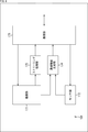
- FIG. 4 is a block diagram showing an example of a main configuration of a base station 102, which is an aspect of an information processing apparatus to which the present technology is applied.
- the base station 102 has a vehicle information acquisition unit 141, an environment information acquisition unit 142, a control unit 143, and a communication unit 144.
- the vehicle information acquisition unit 141 performs processing related to acquisition of vehicle information. For example, the vehicle information acquisition unit 141 acquires the vehicle information of the patrol car 101 supplied from the communication unit 144. The vehicle information acquisition unit 141 supplies the acquired vehicle information to the control unit 143.
- the environmental information acquisition unit 142 performs processing related to the acquisition of environmental information. For example, the environment information acquisition unit 142 acquires environment information supplied from the communication unit 144 (for example, an image captured image, an analysis result of the captured image, an instruction command, etc. transmitted from another device). The environmental information acquisition unit 142 supplies the acquired environmental information to the control unit 143.
- the communication unit 144 for example, an image captured image, an analysis result of the captured image, an instruction command, etc. transmitted from another device.
- the environmental information acquisition unit 142 supplies the acquired environmental information to the control unit 143.
- the control unit 143 performs processing related to control of the image pickup device (aircraft 103 including the camera 112). For example, the control unit 143 acquires the vehicle information supplied from the vehicle information acquisition unit 141. Further, the control unit 143 acquires the environmental information supplied from the environmental information acquisition unit 142. Further, the control unit 143 controls the image pickup device (aircraft 103 including the camera 112) based on the acquired vehicle information or based on the acquired vehicle information and environmental information.
- the control unit 143 has an image pickup control unit 152.
- the image pickup control unit 152 performs processing related to control of image pickup of a subject by the camera 112.
- the imaging control unit 152 generates imaging control information based on vehicle information or based on vehicle information and environmental information.
- the image pickup control unit 152 supplies the generated image pickup control information to the communication unit 144 and transmits the generated image pickup control information to the flying object 103 (camera 112).
- the flying object 103 (camera 112) is driven according to this imaging control information. That is, the image pickup control unit 152 controls the image pickup of the subject by the camera 112 based on the vehicle information or the vehicle information and the environment information.
- control unit 143 may have the flight control unit 151.
- the flight control unit 151 performs processing related to flight control by the flight object 103. For example, the flight control unit 151 generates flight control information based on vehicle information or based on vehicle information and environmental information. Further, the flight control unit 151 supplies the generated flight control information to the communication unit 144 and causes the flight body 103 to transmit the generated flight control information. The aircraft body 103 is driven according to this flight control information. That is, the flight control unit 151 controls the flight by the flying object 103 based on the vehicle information or the vehicle information and the environmental information.
- control unit 143 may have the vehicle control unit 153.
- the vehicle control unit 153 performs processing related to control of the patrol car 101, which is a vehicle. For example, the vehicle control unit 153 generates vehicle control information based on vehicle information or based on vehicle information and environmental information. Further, the vehicle control unit 153 supplies the generated vehicle control information to the communication unit 144 and causes the patrol car 101 to transmit the generated vehicle control information. The patrol car 101 is driven according to this vehicle control information. That is, the vehicle control unit 153 controls the patrol car 101, which is a vehicle, based on the vehicle information or the vehicle information and the environmental information.
- control unit 143 may have the terminal control unit 154.
- the terminal control unit 154 performs processing related to the control of the terminal device 104. For example, the terminal control unit 154 generates terminal control information based on vehicle information or based on vehicle information and environmental information. Further, the terminal control unit 154 supplies the generated terminal control information to the communication unit 144 and causes the terminal device 104 to transmit the generated terminal control information.
- the terminal device 104 is driven according to the terminal control information, and for example, an image is taken or a predetermined information is detected by using a sensor. That is, the terminal control unit 154 controls the terminal device 104 based on the vehicle information or the vehicle information and the environmental information.
- control unit 143 may have the server processing unit 155.
- the server processing unit 155 performs processing on the central control server 105.
- the server processing unit 155 exchanges information with the central control server 105 via the communication unit 144.
- the server processing unit 155 acquires the environment information (instruction command) transmitted from the central control server 105 and received by the communication unit 144 from the communication unit 144.
- the server processing unit 155 supplies the acquired environmental information (instruction command) to the processing unit corresponding to the instruction command in the flight control unit 151 to the terminal control unit 154.
- the server processing unit 155 acquires the streaming data of the captured image transmitted from the flying object 103 (camera 112) and received by the communication unit 144 from the communication unit 144.
- the server processing unit 155 supplies the acquired streaming data to the communication unit 144 and transmits it to the central control server 105 (streaming the captured image to the central control server 105).
- the communication unit 144 has a communication interface and communicates with another device via the communication interface.
- the method (standard) of this communication is arbitrary, and may be wireless communication, wired communication, or both.
- the communication unit 144 communicates with the patrol car 101 (communication unit 133) and receives the vehicle information transmitted from the patrol car 101.
- the communication unit 144 supplies the vehicle information to the vehicle information acquisition unit 141.
- the communication unit 144 may communicate with the flight object 103 (communication unit 165 described later) and receive the environmental information (captured image or the like) transmitted from the flight object 103.
- the communication unit 144 may communicate with the terminal device 104 (communication unit 175 described later) and receive environmental information (captured image or the like) transmitted from the terminal device 104.
- the communication unit 144 may communicate with the central control server 105 (communication unit 183 described later) and receive the environment information (instruction command and the like) transmitted from the central control server 105.
- the communication unit 144 supplies the received environmental information to the environmental information acquisition unit 142.
- the communication unit 144 communicates with the flying object 103 (communication unit 165) and transmits the imaging control information supplied from the control unit 143 (imaging control unit 152) to the flying object 103 (communication unit 165). To do. Further, the communication unit 144 may communicate with the flight object 103 and transmit the flight control information supplied from the control unit 143 (flight control unit 151) to the flight object 103.
- the communication unit 144 may communicate with the patrol car 101 (communication unit 133) and transmit the vehicle control information supplied from the control unit 143 (vehicle control unit 153) to the patrol car 101. Further, the communication unit 144 may communicate with the terminal device 104 and transmit the terminal control information supplied from the control unit 143 (terminal control unit 154) to the terminal device 104 (communication unit 175). Further, the communication unit 144 may communicate with the central control server 105 (communication unit 183) and transmit the streaming data supplied from the control unit 143 (server processing unit 155) to the central control server 105. ..
- each processing unit of the vehicle information acquisition unit 141 to the control unit 143 can have an arbitrary configuration.
- each of these processing units may be configured by a logic circuit that realizes the above processing.
- each of these processing units may have, for example, a CPU, ROM, RAM, etc., and execute a program using them to realize the above-mentioned processing.
- each of these processing units may have both configurations, and a part of the above-mentioned processing may be realized by a logic circuit, and the other may be realized by executing a program.
- the communication unit 144 can have an arbitrary configuration in addition to the communication interface described above.
- the communication unit 144 may have a logic circuit that realizes a control process for controlling the above-mentioned communication interface.
- the communication unit 144 may have, for example, a CPU, ROM, RAM, etc., and execute a program using them to realize the control process.
- the communication unit 144 may have both configurations, a part of the control process may be realized by a logic circuit, and the other may be realized by executing a program.
- the configurations of the respective processing units may be independent of each other.
- some processing units realize processing by a logic circuit, and some other processing units realize processing. May realize the processing by executing the program, and the other processing unit may realize the processing by both the logic circuit and the execution of the program.
- the environmental information acquisition unit 142 can be omitted. Further, when the control unit 143 does not control the flight of the flying object 103, the flight control unit 151 can be omitted. Further, when the control unit 143 does not control the patrol car 101, the vehicle control unit 153 can be omitted. Further, when the control unit 143 does not control the terminal device 104, the terminal control unit 154 can be omitted. Further, when the control unit 143 does not exchange information with the central control server 105, the server processing unit 155 can be omitted.
- FIG. 5 is a block diagram showing an example of a main configuration of a flying object 103, which is an aspect of an imaging device (or a moving body) to which the present technology is applied.
- the flying object 103 includes a flight unit 161, an imaging unit 162, an environmental information generation unit 163, a streaming processing unit 164, and a communication unit 165.
- the flight unit 161 has a configuration related to the flight of the flying object 103, and performs processing related to the flight of the flying object 103.
- the flight configuration includes, for example, a propeller, a motor, and a control unit that controls them.
- the flight unit 161 drives, for example, these configurations to fly the flying object 103.
- the flight unit 161 has a configuration for acquiring information to be included in the environmental information from the configuration related to this flight.
- the information included in this environmental information includes, for example, flight-related information such as the position, attitude (direction, inclination, etc.), speed, and rotation speed of the propeller of the flying object 103.
- information about the periphery of the flying object 103 such as the temperature and the wind speed may be included.
- a positioning unit for positioning the position of the flying object 103 using GPS signals, a gyro sensor for detecting the attitude and speed, and the rotation speed of the propeller are included.
- a configuration for acquiring information regarding flight such as a sensor for detecting, may be included.
- a configuration for acquiring information about the periphery of the flying object 103, such as a temperature sensor and a wind speed sensor, may be included.
- a control unit for controlling those sensors and the like may be included.
- the flight unit 161 acquires flight control information (flight control information transmitted from the base station 102) supplied from the communication unit 165.
- the flight unit 161 flies the flight object 103 according to the acquired flight control information. Further, the flight unit 161 acquires the information to be included in the environmental information and supplies the information to the environmental information generation unit 163.
- the imaging unit 162 has, for example, a camera 112 and a control unit that controls the drive and posture (direction, tilt, etc.) of the camera 112, and performs processing related to imaging the subject.
- the imaging unit 162 acquires the imaging control information (imaging control information transmitted from the base station 102) supplied from the communication unit 165.
- the imaging unit 162 images a subject using the camera 112 according to the acquired imaging control information.
- the imaging unit 162 sets parameters related to imaging (exposure, timing, shutter speed, imaging position, imaging direction, angle of view, image processing, etc.) according to imaging control information, performs imaging, and generates an captured image.
- the imaging unit 162 supplies the generated captured image to the environment information generation unit 163 as information to be included in the environment information. Further, the imaging unit 162 may analyze the generated captured image for predetermined information and supply the analysis result to the environment information generation unit 163 as information to be included in the environment information. Further, the imaging unit 162 may supply the generated captured image to the streaming processing unit 164.
- the environmental information generation unit 163 performs processing related to the generation of environmental information. For example, the environment information generation unit 163 acquires the captured image (or its analysis result) supplied from the imaging unit 162. The environmental information generation unit 163 generates environmental information including the captured image (or its analysis result), and supplies the generated environmental information to the communication unit 165. Further, for example, the environmental information generation unit 163 acquires information regarding the flight supplied from the flight unit 161 as information to be included in the environmental information. Further, the environmental information generation unit 163 acquires information on the periphery of the flying object 103 supplied from the flight unit 161 as information to be included in the environmental information. The environmental information generation unit 163 generates environmental information including such information, and supplies the generated environmental information to the communication unit 165.
- Streaming processing unit 164 performs processing related to streaming distribution of captured images. For example, the streaming processing unit 164 acquires an captured image (flying object captured image) supplied from the imaging unit 162. The streaming processing unit 164 supplies the captured image of the flying object to the communication unit 165 as streaming data.
- the streaming processing unit 164 acquires an captured image (flying object captured image) supplied from the imaging unit 162. The streaming processing unit 164 supplies the captured image of the flying object to the communication unit 165 as streaming data.
- the communication unit 165 has a communication interface and communicates with other devices via the communication interface.
- the method (standard) of this communication is arbitrary, and may be wireless communication, wired communication, or both.
- the communication unit 165 communicates with the base station 102 (communication unit 144) and receives the imaging control information transmitted from the base station 102.
- the communication unit 165 supplies the received image pickup control information to the image pickup unit 162.
- the imaging unit 162 can perform imaging based on the imaging control information.
- the communication unit 165 may communicate with the base station 102 (communication unit 144) and receive the flight control information transmitted from the base station 102. In that case, the communication unit 165 supplies the received flight control information to the flight unit 161. As a result, the flight unit 161 can fly based on the flight control information.
- the communication unit 165 may acquire the environmental information supplied from the environmental information generation unit 163, communicate with the base station 102 (communication unit 144), and transmit the environmental information to the base station 102. .. Further, the communication unit 165 acquires the streaming data (aircraft image) supplied from the streaming processing unit 164, communicates with the base station 102 (communication unit 144), and transmits the streaming data to the base station 102. You may do so.
- each processing unit of the environment information generation unit 163 and the streaming processing unit 164 can have an arbitrary configuration.
- each of these processing units may be configured by a logic circuit that realizes the above processing.
- each of these processing units may have, for example, a CPU, ROM, RAM, etc., and execute a program using them to realize the above-mentioned processing.
- each of these processing units may have both configurations, and a part of the above-mentioned processing may be realized by a logic circuit, and the other may be realized by executing a program.
- each processing unit of the flight unit 161, the image pickup unit 162, and the communication unit 165 can have an arbitrary configuration in addition to the above-described configuration.
- each processing unit may have a logic circuit that realizes a control process for controlling the above-described configuration.
- each processing unit may have, for example, a CPU, ROM, RAM, or the like, and the control processing may be realized by executing a program using them.
- each processing unit may have both configurations, a part of the control processing may be realized by a logic circuit, and the other may be realized by executing a program.
- each processing unit may be independent of each other. For example, some processing units realize processing by a logic circuit, and some other processing units realize processing by executing a program. In addition, another processing unit may realize the processing by both the logic circuit and the execution of the program.
- the environmental information generation unit 163 can be omitted. Further, when streaming distribution of the captured image is not performed, the streaming processing unit 164 can be omitted.
- FIG. 6 is a block diagram showing an example of a main configuration of a terminal device 104, which is an aspect of an information processing device to which the present technology is applied.
- the terminal device 104 includes an image pickup unit 171, a sensor unit 172, a streaming processing unit 173, an environment information generation unit 174, and a communication unit 175.
- the imaging unit 171 performs processing related to imaging the subject. For example, the imaging unit 171 sets parameters related to imaging (exposure, timing, shutter speed, imaging position, imaging direction, angle of view, image processing, etc.), or images a subject to generate an captured image. Further, the imaging unit 171 supplies the captured image to the environment information generation unit 174 as information to be included in the environment information. The image pickup unit 171 may analyze the generated captured image for predetermined information, and supply the analysis result to the environment information generation unit 174 as information to be included in the environment information. Further, the imaging unit 171 may supply the generated captured image to the streaming processing unit 173.
- the imaging unit 171 sets parameters related to imaging (exposure, timing, shutter speed, imaging position, imaging direction, angle of view, image processing, etc.), or images a subject to generate an captured image. Further, the imaging unit 171 supplies the captured image to the environment information generation unit 174 as information to be included in the environment information. The image pickup unit 171 may analyze the generated captured image for predetermined information, and supply the analysis result to the environment
- the imaging unit 171 may acquire the terminal control information (terminal control information transmitted from the base station 102) supplied from the communication unit 175. Then, the imaging unit 171 may perform the above-mentioned processing (imaging, etc.) based on the terminal control information.
- the sensor unit 172 has a sensor, a control unit that controls the sensor, and the like, and performs processing related to information detection.
- This sensor may detect any information.
- this sensor may be a sensor that detects the surrounding state of the police officer 113, such as a microphone, a temperature sensor, a humidity sensor, a brightness sensor, an invisible light sensor such as infrared rays, or a terminal device such as a gyro sensor. It may be a sensor that detects the posture and movement of 104, or it may be a sensor that detects biological information of police officer 113 such as heart rate, pulse, and line-of-sight direction. Further, the number of sensors constituting the sensor unit 172 is arbitrary. It may be singular or plural. Further, the sensor unit 172 may have a plurality of sensors that detect different types of information. Of course, one sensor may be able to detect a plurality of types of information.
- the sensor unit 172 supplies the information (sensor information) detected by using such a sensor to the environmental information generation unit 174 as information to be included in the environmental information.
- the sensor unit 172 may acquire the terminal control information (terminal control information transmitted from the base station 102) supplied from the communication unit 175. Then, the sensor unit 172 may perform the above-mentioned processing (information detection, etc.) based on the terminal control information.
- the streaming processing unit 173 performs processing related to streaming distribution of the captured image (terminal captured image) generated by the imaging unit 171. For example, the streaming processing unit 173 acquires an captured image supplied from the imaging unit 171. The streaming processing unit 173 supplies the captured image as streaming data to the communication unit 175.
- the environmental information generation unit 174 performs processing related to the generation of environmental information. For example, the environment information generation unit 174 acquires a terminal image (or an analysis result thereof) supplied from the image pickup unit 171. The environment information generation unit 174 generates environment information including the terminal image (or its analysis result), and supplies the generated environment information to the communication unit 175. Further, for example, the environmental information generation unit 174 acquires the sensor information supplied from the sensor unit 172 as the information to be included in the environmental information. The environmental information generation unit 174 generates environmental information including the sensor information, and supplies the generated environmental information to the communication unit 175.
- the communication unit 175 has a communication interface and communicates with other devices via the communication interface.
- the method (standard) of this communication is arbitrary, and may be wireless communication, wired communication, or both.
- the communication unit 175 acquires the environmental information supplied from the environmental information generation unit 174, communicates with the base station 102 (communication unit 144), and transmits the environmental information to the base station 102. Further, the communication unit 175 acquires the streaming data supplied from the streaming processing unit 173, communicates with the base station 102 (communication unit 144), and transmits the streaming data to the base station 102.
- the communication unit 175 communicates with the base station 102 (communication unit 144) and receives the terminal control information transmitted from the base station 102.
- the communication unit 175 supplies the received terminal control information to the image pickup unit 171 and the sensor unit 172.
- the imaging unit 171 and the sensor unit 172 can perform imaging based on the terminal control information.
- each processing unit of the streaming processing unit 173 and the environment information generation unit 174 can have an arbitrary configuration.
- each of these processing units may be configured by a logic circuit that realizes the above processing.
- each of these processing units may have, for example, a CPU, ROM, RAM, etc., and execute a program using them to realize the above-mentioned processing.
- each of these processing units may have both configurations, and a part of the above-mentioned processing may be realized by a logic circuit, and the other may be realized by executing a program.
- each processing unit of the imaging unit 171, the sensor unit 172, and the communication unit 175 can have an arbitrary configuration in addition to the above-described configuration.
- each processing unit may have a logic circuit that realizes a control process for controlling the above-described configuration.
- each processing unit may have, for example, a CPU, ROM, RAM, or the like, and the control processing may be realized by executing a program using them.
- each processing unit may have both configurations, a part of the control processing may be realized by a logic circuit, and the other may be realized by executing a program.
- each processing unit may be independent of each other. For example, some processing units realize processing by a logic circuit, and some other processing units realize processing by executing a program. In addition, another processing unit may realize the processing by both the logic circuit and the execution of the program.
- the environmental information generation unit 174 can be omitted. Further, when streaming distribution of the captured image is not performed, the streaming processing unit 173 can be omitted.
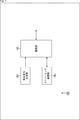
- FIG. 7 is a block diagram showing an example of a main configuration of a central control server 105, which is an aspect of an information processing device to which the present technology is applied.
- the central control server 105 includes an instruction command generation unit 181, a streaming processing unit 182, and a communication unit 183.
- the instruction command generation unit 181 performs processing related to generation of instruction commands for other devices of the patrol support system 100.
- the instruction command generation unit 181 receives, for example, a user (operator) operation for a user interface (not shown), and generates an instruction command based on the user operation or the like.
- the instruction command generation unit 181 supplies the generated instruction command to the communication unit 183 as environmental information.
- the communication unit 183 has a communication interface, and communicates with another device via the communication interface.
- the method (standard) of this communication is arbitrary, and may be wireless communication, wired communication, or both.
- the communication unit 183 acquires the environment information (including the instruction command) supplied from the instruction command generation unit 181, communicates with the base station 102 (communication unit 144), and bases the environment information (instruction command). Send to station 102. Further, the communication unit 183 receives the streaming data transmitted from the base station 102 and supplies it to the streaming processing unit 182.
- the streaming processing unit 182 acquires the streaming data supplied from the communication unit 183 and reproduces and displays it. As a result, the operator can view the captured image to be streamed. As a result, the operator can more easily grasp the situation around the patrol car 101 and the police officer 113. Therefore, more appropriate instructions can be given depending on the situation.
- each processing unit of the instruction command generation unit 181 and the streaming processing unit 182 can have an arbitrary configuration.
- each of these processing units may be configured by a logic circuit that realizes the above processing.
- each of these processing units may have, for example, a CPU, ROM, RAM, etc., and execute a program using them to realize the above-mentioned processing.
- each of these processing units may have both configurations, and a part of the above-mentioned processing may be realized by a logic circuit, and the other may be realized by executing a program.
- each communication unit 183 can have an arbitrary configuration in addition to the above-described configuration.
- the communication unit 183 may have a logic circuit that realizes a control process for controlling the above configuration.
- each processing unit may have, for example, a CPU, ROM, RAM, or the like, and the control processing may be realized by executing a program using them.
- each processing unit may have both configurations, a part of the control processing may be realized by a logic circuit, and the other may be realized by executing a program.
- each processing unit may be independent of each other. For example, some processing units realize processing by a logic circuit, and some other processing units realize processing by executing a program. In addition, another processing unit may realize the processing by both the logic circuit and the execution of the program.
- the streaming processing unit 182 can be omitted.
- Each device has the above configuration, and by performing the above-mentioned processing, it is possible to more easily perform imaging according to various situations.
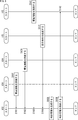
- the vehicle information generation unit 132 of the patrol car 101 When the control process is started, the vehicle information generation unit 132 of the patrol car 101 generates vehicle information including the information supplied from the vehicle unit 131 in step S111. Then, the communication unit 133 supplies the vehicle information to the base station 102. In step S101, the communication unit 144 of the base station 102 acquires the vehicle information.
- step S121 the environment information generation unit 174 of the terminal device 104 generates environment information including the terminal captured image. Then, the communication unit 175 supplies the environmental information to the base station 102. In step S102, the communication unit 144 of the base station 102 acquires the environmental information.
- step S141 the environmental information generation unit 163 of the flying object 103 generates environmental information including the image captured by the flying object. Then, the communication unit 165 supplies the environmental information to the base station 102. In step S103, the communication unit 144 of the base station 102 acquires the environmental information.
- step S131 the instruction command generation unit 181 of the central control server 105 generates an instruction command (including environment information). Then, the communication unit 183 supplies the instruction command to the base station 102. In step S104, the communication unit 144 of the base station 102 acquires the environmental information (instruction command).
- step S105 the control unit 143 of the base station 102 generates control information by appropriately using the information acquired in steps S101 to S104.
- the imaging control unit 152 generates imaging control information by appropriately using the supplied vehicle information and environmental information.
- the flight control unit 151 generates flight control information by appropriately using the supplied vehicle information and environmental information.
- step S105 the vehicle control unit 153 may generate vehicle control information by appropriately using the supplied vehicle information and environmental information. Further, the terminal control unit 154 may generate the terminal control information by appropriately using the supplied vehicle information and environmental information.
- step S106 the communication unit 144 of the base station 102 transmits control information such as imaging control information and vehicle control information generated in step S105 to the flying object 103.
- step S142 the communication unit 165 of the flying object 103 acquires the control information (imaging control information, vehicle control information, etc.).
- the flight unit 161 of the flight body 103 flies according to the flight control information. Further, the imaging unit 162 of the flying object 103 images the subject according to the imaging control information.
- the communication unit 144 may transmit the vehicle control information to the communication unit 133 of the patrol car 101 in step S106. In that case, the vehicle unit 131 is driven according to the vehicle control information acquired by the communication unit 133.
- the communication unit 144 may transmit the terminal control information to the communication unit 175 of the terminal device 104 in step S106.
- the imaging unit 171 and the sensor unit 172 perform processing according to the terminal control information acquired by the communication unit 175.
- step S105 of FIG. 8 an example of the flow of the flight object control process executed by the base station 102 will be described with reference to the flowchart of FIG.
- the vehicle information acquisition unit 141 acquires the vehicle information transmitted from the patrol car 101 via the communication unit 144 in step S201.
- step S202 the environmental information acquisition unit 142 acquires the environmental information transmitted from the flying object 103 and the terminal device 104 via the communication unit 144.
- step S203 the flight control unit 151 generates flight control information based on the vehicle information acquired in step S201, or based on the vehicle information and the environmental information acquired in step S202.
- step S204 the communication unit 144 transmits the flight control information generated in step S203 to the flying object 103.
- the flight body 103 flies according to this flight control information. That is, the flight control unit 151 of the base station 102 controls the flight of the flying object 103 based on the vehicle information or the vehicle information and the environmental information.
- step S205 the imaging control unit 152 generates imaging control information based on the vehicle information acquired in step S201, or based on the vehicle information and the environmental information acquired in step S202.
- step S206 the communication unit 144 transmits the imaging control information generated in step S205 to the flying object 103 (camera 112).
- the flying object 103 images the subject according to the image pickup control information. That is, the image pickup control unit 152 of the base station 102 controls the image pickup of the subject by the camera 112 based on the vehicle information or the vehicle information and the environment information.
- step S206 When the process of step S206 is completed, the aircraft control process is completed. By executing each process in this way, it is possible to more easily perform imaging according to various situations.
- the base station 102 may control the flying object 103 and land on the base station 102 when the patrol car 101 starts (accelerates from 0 km / h).
- the base station 102 detects the start of the patrol car 101 based on the vehicle speed information included in the vehicle information, for example, it generates flight control information for landing the vehicle 103 at the base station 102 (predetermined position).
- the flight control information is transmitted to the aircraft 103.
- the aircraft body 103 lands on the base station 102 according to the flight control information.
- the base station 102 may control the flying object 103 and land on the base station 102 when the started patrol car 101 accelerates and reaches a predetermined speed (for example, 10 km / h or the like).
- a predetermined speed for example, 10 km / h or the like.
- the base station 102 detects that the speed of the patrol car 101 has reached a predetermined speed based on the vehicle speed information included in the vehicle information, for example, the aircraft body 103 is moved to the base station 102 (predetermined position).
- the flight control information for landing is generated, and the flight control information is transmitted to the aircraft 103.
- the aircraft body 103 lands on the base station 102 according to the flight control information.
- the base station 102 may control the aircraft 103 and land on the base station 102 when the police officer 113 or the like performs a predetermined start preparation operation (before the start) in the patrol car 101. Good.
- This preparatory movement for starting is optional. For example, opening and closing the door (of the driver's seat) of the patrol car 101, wearing a seatbelt, gripping the steering wheel, turning on the engine key, releasing the brake pedal, operating the shift lever, releasing the parking brake, lighting the rotating light, and the like. May be good.
- the operation may be other than these.
- the start preparation operation may be a combination of a plurality of operations. For example, when the steering operation, the release of the brake pedal, or the like is detected while the door is closed, it may be determined that the operation is preparation for starting.
- the base station 102 detects a start preparation operation based on, for example, vehicle operation information and vehicle equipment information included in the vehicle information, the flight control for landing the vehicle body 103 at the base station 102 (predetermined position). Information is generated and the flight control information is transmitted to the aircraft 103. The aircraft body 103 lands on the base station 102 according to the flight control information.
- the base station 102 may end the imaging by the camera 112 when the flying object 103 is landed as described above.
- the base station 102 detects the trigger conditions such as the start of the patrol car 101, the acceleration of the patrol car 101 to a predetermined speed, and the start preparation operation of the patrol car 101 as described above based on the vehicle information
- the flight control information is transmitted to the flying object 103 to land the flying object 103
- the imaging control information is transmitted to the flying object 103 (camera 112) to end the imaging by the camera 112.
- the moving speed of the flying object 103 (about 10 km / h to 20 km / h) is slower than the normal moving speed of the patrol car 101 (for example, about 40 km / h to 50 km / h). Therefore, it is difficult to move the patrol car 101 at a normal moving speed while flying the flying object 103. In other words, it is difficult to fly the flying object 103 normally while the patrol car 101 is moving at a normal moving speed. That is, it becomes difficult for the camera 112 to take an image in a meaningful state, and even if an image is taken, there is a high possibility that only an image that is unstable and difficult to be used for patrol support can be obtained.
- the patrol car 101 is moving at a normal moving speed and the flying object 103 is made to fly and take an image, the contribution of the patrol support is low, and conversely, the safety may be reduced. .. In addition, there is a risk that the flying object 103 may be damaged due to unstable flight.
- the police officer 113 who drives the patrol car 101 patrols more easily, safely, and at high speed.
- the car 101 can be moved.
- the captured image captured and generated by the camera 112 of the flying object 103 by the time the imaging is completed may be recorded at an arbitrary location.
- the base station 102 may record the captured image.
- the central control server 105 may record the captured image.
- another device may record the captured image.
- the flight altitude (aircraft altitude) of the flying object 103 is controlled (that is, the altitude of the camera 112 is controlled) according to the moving speed (vehicle speed) of the patrol car 101. It may be.
- the base station 102 may be controlled so that the higher the vehicle speed is, the lower the vehicle altitude is, and the slower the vehicle speed is, the higher the vehicle altitude is.
- the base station 102 controls the flight altitude of the vehicle according to the vehicle speed, lowers the vehicle altitude as the vehicle speed increases, and increases the flight altitude as the vehicle speed decreases. To do.
- the base station 102 causes the aircraft 103 to fly at the maximum altitude when the patrol car 101 is stopped, lowers the altitude of the aircraft 103 as the moving speed of the patrol car 101 increases, and the speed of the patrol car 101. Will land the aircraft 103 at the base station 102 when it reaches a predetermined limit speed.
- the base station 102 may end the imaging by the camera 112.
- the flight control when the base station 102 detects the moving speed of the patrol car 101 based on the vehicle speed information included in the vehicle information, for example, the flight control causes the flying object 103 to fly at an altitude corresponding to the moving speed. Information is generated and the flight control information is transmitted to the aircraft 103. The aircraft body 103 flies at the altitude specified by the flight control information.
- the patrol support system 100 can fly the flying object 103 more safely (take an image more safely) at a wider variety of vehicle speeds (moving speed of the patrol car 101). can do. That is, the patrol support system 100 can more appropriately perform patrol support under more diverse situations.
- the altitude of the flying object 103 may be controlled based on the flying object image (environmental information) imaged and generated by the camera 112. For example, when an obstacle such as a signal or a roof is detected by analyzing an image captured by a flying object, the flight altitude may be lowered in order to avoid the obstacle.
- the altitude control of the flying object 103 based on such an image captured by the flying object may be performed by the flying object 103 (camera 112) itself or may be performed by the base station 102.
- the base station 102 may be able to control arbitrary parameters related to imaging together with the flight altitude.
- any parameters related to imaging such as imaging start / end, resolution, aperture, sensitivity, depth of field, angle of view (zoom, pan, tilt), orientation, or image processing (white balance adjustment, filter processing, etc.) It may be controlled.
- the captured image captured and generated by the camera 112 of the flying object 103 may be recorded at an arbitrary location by the time the imaging is completed.
- the base station 102 may record the captured image.
- the central control server 105 may record the captured image.
- another device may record the captured image.
- Use case 2 (takeoff control)>
- the base station 102 controls the flying object 103 based on the operation and the situation of the patrol car 101 near the time when it is stopped, and takes off from the base station 102.
- the police officer 113 may perform some activity. For example, it is conceivable that police officer 113 gets off the patrol car 101 and shifts to patrol on foot, or asks a suspicious person a job question. It is also conceivable that the police officer 113 monitors the vicinity from the inside of the patrol car 101. To support such activities, the base station 102 takes off the flying object 103 and causes the camera 112 to start imaging in response to the stop of the patrol car 101. By doing so, it is possible to support the police officer 113 by using the flight object captured image generated by the camera 112.
- the area around the patrol car 101 and the police officer 113 can be monitored using the image captured by the flying object, and necessary information can be appropriately notified to the police officer 113 and the like.
- the captured image of the flying object can be analyzed to detect the occurrence of an abnormality or the appearance of a suspicious person, and the police officer 113 can be notified of the occurrence of the abnormality or the danger.
- the police officer 113 and the patrol car 101 can be guided or guided based on the captured image of the flying object.
- the action of the police officer 113 can be monitored or recorded based on the image captured by the flying object.
- the base station 102 may control the flying object 103 and take off from the base station 102 when the patrol car 101 stops (decelerates and reaches 0 km / h).
- the base station 102 detects the stop of the patrol car 101 based on the vehicle speed information included in the vehicle information, for example, the base station 102 generates flight control information for taking off the flying object 103 from the base station 102 (predetermined position).
- the flight control information is transmitted to the aircraft 103.
- the aircraft body 103 takes off from the base station 102 according to the flight control information.
- the base station 102 may control the flying object 103 and take off from the base station 102 when the started patrol car 101 decelerates and reaches a predetermined speed or less (for example, 20 km / h or less). ..
- a predetermined speed or less for example, 20 km / h or less.
- the aircraft body 103 is set to the base station 102 (predetermined).
- the flight control information for taking off from the position) is generated, and the flight control information is transmitted to the aircraft 103.
- the aircraft body 103 takes off from the base station 102 according to the flight control information.
- the base station 102 may start imaging by the camera 112 when the flying object 103 is taken off as described above. For example, when the base station 102 detects the stoppage of the patrol car 101 or the deceleration to a predetermined speed or less of the patrol car 101 as described above based on the vehicle information, the base station 102 transmits the flight control information to the flying object 103. Then, the aircraft 103 is taken off, and the imaging control information is transmitted to the aircraft 103 (camera 112) to start imaging by the camera 112.
- the police officer 113 may drive the patrol car 101 even when he is not on patrol. For example, a police officer 113 may drive a patrol car 101 to go to work or return home from home. Further, for example, at a police station or the like, a patrol car 101 may be driven to move. Further, the police officer 113 may drive the patrol car 101 to go out for a meal during the break. In these cases, since it is not a patrol, it is not necessary to fly the flying object 103 and monitor the surroundings.
- the aircraft 103 may be controlled to take off in response to the stop of the patrol car 101 only when the condition indicating that the patrol car is in progress is satisfied. Any condition may be used to indicate that the patrol is in progress. For example, if the engine does not turn off (remains on) for a predetermined time (for example, a few seconds) after the patrol car 101 is stopped, the base station 102 controls the aircraft 103 to take off as described above. You may.
- the base station 102 may control the flying object 103 to take off as described above. Further, for example, when the patrol car 101 stops with the revolving light turned on, the base station 102 may control the flying object 103 to take off as described above.
- the stop position of the patrol car 101 is specified based on the vehicle position / attitude information (including the positioning result using GPS signals) of the vehicle information, and the stop position of the patrol car 101 is, for example, a police station or a home.
- the base station 102 may control the flying object 103 to take off as described above.
- the base station 102 may cause the camera 112 to start imaging when the flying object 103 is taken off as described above. Further, the base station 102 may stream the image captured by the flying object generated by the camera 112 to, for example, the central control server 105. Further, the flying object captured image generated by the camera 112 may be recorded at an arbitrary place. For example, the base station 102 may record the captured image. Further, the central control server 105 may record the captured image. Further, another device may record the captured image.
- the base station 102 may raise the take-off flying object 103 to the maximum altitude to monitor the surroundings of the patrol car 101 (image the surroundings). Then, when the police officer 113 gets off the patrol car 101, the base station 102 may lower the flying object 103 that has risen to the maximum altitude to image the vicinity of the police officer 113. By doing so, the flying object 103 can be made to monitor the area around the patrol car 101 when the police officer 113 is in the car, and the area around the police officer 113 when the police officer 113 gets off. .. That is, it is possible to more easily perform imaging according to various situations. As a result, the patrol support system 100 can provide more appropriate support in more diverse situations.
- the base station 102 may control the angle of view and the like for capturing the subject by the camera 112. For example, as described above, when the take-off flying object 103 is raised to the maximum altitude to monitor the periphery of the patrol car 101 (to image the periphery), the base station 102 widens the angle of view of the camera 112. Set. Further, when the flying object 103 is used to image the periphery of the police officer 113, the base station 102 sets the angle of view of the camera 112 to a narrow angle. By doing so, it is possible to perform imaging at an appropriate angle of view according to the subject. As a result, the patrol support system 100 can provide more appropriate support in more diverse situations.
- the base station 102 can control any parameter related to imaging, not limited to the angle of view.
- panoramic photography may be performed, depth estimation may be performed, or stitching may be performed.
- Use case 3 (tracking)>
- the base station 102 controls the flying object 103 to track the police officer 113 so as to image the police officer 113 who got off the patrol car 101 and its surroundings.
- the patrol support system 100 can support the behavior monitoring and the like of the police officer 113, and can also support the safety management and the like of the police officer 113.
- the base station 102 identifies (or estimates) the position of the police officer 113 in order for the flying object 103 to track the police officer 113.
- This method is optional.
- the position of the police officer 113 may be derived from a GPS signal or the like by using the terminal device 104 carried by the police officer 113.
- the base station 102 identifies whether or not the police officer 113 has disembarked from the patrol car 101.
- the police officer 113 gets off based on the position information of the police officer 113 (terminal device 104) derived by the terminal device 104, the opening / closing detection of the door, and the analysis result of the terminal captured image generated by the terminal device 104. It may be determined whether or not it has been done.
- the base station 102 may allow the patrol car 101 to start tracking and record the captured image. This recording may be performed at the base station 102, at the central control server 105, or at another device. In addition, streaming distribution of the captured image may be started. Further, at the start of tracking, a bookmark may be inserted into the captured image or metadata may be added. It should be noted that such an event may be triggered when the police officer 113, which is tracked by the flying object 103, uses a weapon (for example, when the gun is pulled out from the holder).
- the base station 102 may control the angle of view of the imaging image.
- the angle of view zoom, pan, tilt, etc.
- position, orientation, tilt, height, and other arbitrary parameters related to imaging by the camera 112 may be controlled.
- the camera 112 may take an image at a position or attitude such that the line-of-sight direction of the police officer 113 is widened in the captured image.
- the base station 102 may control the flight of the flying object 103 so that the camera 112 can perform such an imaging. By doing so, the line-of-sight direction of the police officer 113 can be monitored intensively.
- the camera 112 may take an image at a position or posture such that the police officer 113 is located at the center of the image in the captured image.
- the base station 102 may control the flight of the flying object 103 so that the camera 112 can perform such an imaging. By doing so, monitoring can be performed without causing bias depending on the direction.
- the camera 112 may perform imaging at a position or posture in which the opposite direction of the line-of-sight direction of the police officer 113 is widened in the captured image. By doing so, it is possible to widely monitor the direction opposite to the line-of-sight direction of the police officer 113 (the occipital side of the police officer 113). Therefore, the safety of police officer 113 can be improved.
- the camera 112 may take an image at a position or posture in which the direction of the weapon of the police officer 113 is widened in the captured image. By doing so, the police officer 113 can widely monitor the direction in which the weapon is directed. Therefore, the actions of police officer 113 can be controlled more accurately.
- the base station 102 may direct the camera 112 toward the sound source to take an image.
- the flying object 103 can take an image of the side where the abnormality has occurred.
- Use case 4 peripheral monitoring>
- the base station 102 controls the flying object 103 to fly so as to image the periphery of the patrol car 101.
- the base station 102 ends the tracking of the police officer 113 and makes it fly around the police car 101 to monitor it.
- the patrol support system 100 can monitor the vicinity of the patrol car 101 and detect an abnormality occurring in the vicinity of the patrol car 101.
- the base station 102 makes the flying object 103 fly at a constant height, and further rotates the flying object 103 (or the camera 112) to image in all directions (360 degrees).
- the angle of view may be wide or narrow. Anomaly detection and suspicious person detection are performed using the omnidirectional captured image generated in this way. By doing so, the base station 102 can appropriately monitor the vicinity of the patrol car 101.
- this captured image may be recorded.
- the base station 102 or the central control server 105 may record this captured image.
- other devices may record this captured image.
- a plurality of microphones may be provided on the flying object 103, and the voices around the patrol car 101 may be recorded by the plurality of microphones.
- the base station 102 identifies the sound generation direction based on the collected sound, controls the flying object 103, and directs the camera 112 to the sound generation direction (images the sound generation direction). You may do so.
- the image pickup apparatus includes a camera 112 as an image pickup function unit for imaging a subject, and the flying object 103 as an image pickup range variable unit for changing the image pickup range (controlling the image pickup range) by the image pickup function unit.
- each of the image pickup function unit and the image pickup range variable unit may have an arbitrary configuration.
- the variable imaging range portion is not limited to a flying object, and may be an automobile, a ship, or the like. That is, the image pickup range variable portion may be an arbitrary moving body.
- the image pickup range variable unit may be a drive unit capable of controlling the posture and the like of the image pickup function unit. For example, as shown in FIG.
- the image pickup function unit is a camera 302 installed on a pole-shaped installation base mounted on the automobile 301, and the image pickup range variable unit is the direction and height of the camera 302. It may be an installation stand or a drive unit (not shown) to be controlled.
- the pole-shaped installation base has a movable portion that can be expanded and contracted, rotated, and the like, and the driving portion can control the position and orientation of the camera 302 by driving the movable portion.
- the drive unit may shorten the installation base to store the camera 302 in the storage unit for the camera 302 of the automobile 301, or extend the installation base to project the camera 302 above the automobile 301 as shown in FIG.
- the orientation of the camera 302 can be controlled by rotating the installation table around its longitudinal direction.
- the imaging function unit is not limited to the sensor that detects visible light, and may be any sensor.
- the imaging function unit may be a sensor that detects invisible light such as infrared light or ultraviolet light, or may be a sensor that detects voice.
- the patrol car 101 has been described as an example of the vehicle, but this is an example and does not have to be a patrol car.
- it may be an ambulance, a fire engine, a truck, or the like.
- it does not have to be such a special vehicle or a large vehicle, and may be, for example, a general vehicle (ordinary vehicle).
- the above-mentioned "vehicle” that generates vehicle information is not limited to an automobile.
- ships, aircraft, trains (including trains, etc.) are also included in this "vehicle".
- the series of processes described above can be executed by hardware or by software.
- the programs constituting the software are installed on the computer.
- the computer includes a computer embedded in dedicated hardware, a general-purpose personal computer capable of executing various functions by installing various programs, and the like.
- FIG. 16 is a block diagram showing a configuration example of computer hardware that executes the above-mentioned series of processes programmatically.
- the CPU Central Processing Unit
- ROM Read Only Memory
- RAM Random Access Memory
- the input / output interface 910 is also connected to the bus 904.
- An input unit 911, an output unit 912, a storage unit 913, a communication unit 914, and a drive 915 are connected to the input / output interface 910.
- the input unit 911 includes, for example, a keyboard, a mouse, a microphone, a touch panel, an input terminal, and the like.
- the output unit 912 includes, for example, a display, a speaker, an output terminal, and the like.
- the storage unit 913 includes, for example, a hard disk, a RAM disk, a non-volatile memory, or the like.
- the communication unit 914 includes, for example, a network interface.
- the drive 915 drives a removable medium 921 such as a magnetic disk, an optical disk, a magneto-optical disk, or a semiconductor memory.
- the CPU 901 loads the program stored in the storage unit 913 into the RAM 903 via the input / output interface 910 and the bus 904 and executes the above-described series. Is processed.
- the RAM 903 also appropriately stores data and the like necessary for the CPU 901 to execute various processes.
- the program executed by the computer can be recorded and applied to the removable media 921 as a package media or the like, for example.
- the program can be installed in the storage unit 913 via the input / output interface 910 by mounting the removable media 921 in the drive 915.
- This program can also be provided via wired or wireless transmission media such as local area networks, the Internet, and digital satellite broadcasting. In that case, the program can be received by the communication unit 914 and installed in the storage unit 913.
- this program can be installed in advance in ROM 902 or storage unit 913.
- the present technology can be applied to any configuration.
- the present technology includes a processor as a system LSI (Large Scale Integration) or the like (for example, a video processor), a module using a plurality of processors (for example, a video module), a unit using a plurality of modules (for example, a video unit), or , A set in which other functions are added to the unit (for example, a video set), etc., can be implemented as a partial configuration of the device.
- LSI Large Scale Integration
- this technology can be applied to a network system composed of a plurality of devices.
- the present technology may be implemented as cloud computing that is shared and jointly processed by a plurality of devices via a network.
- this technology is implemented in a cloud service that provides services related to images (moving images) to arbitrary terminals such as computers, AV (AudioVisual) devices, portable information processing terminals, and IoT (Internet of Things) devices. You may try to do it.
- the system means a set of a plurality of components (devices, modules (parts), etc.), and it does not matter whether all the components are in the same housing. Therefore, a plurality of devices housed in separate housings and connected via a network, and a device in which a plurality of modules are housed in one housing are both systems. ..
- Systems, devices, processing departments, etc. to which this technology is applied can be used in any field such as transportation, medical care, crime prevention, agriculture, livestock industry, mining, beauty, factories, home appliances, weather, nature monitoring, etc. .. The use is also arbitrary.
- the configuration described as one device (or processing unit) may be divided and configured as a plurality of devices (or processing units).
- the configurations described above as a plurality of devices (or processing units) may be collectively configured as one device (or processing unit).
- a configuration other than the above may be added to the configuration of each device (or each processing unit).
- a part of the configuration of one device (or processing unit) may be included in the configuration of another device (or other processing unit). ..
- the above-mentioned program may be executed in any device.
- the device may have necessary functions (functional blocks, etc.) so that necessary information can be obtained.
- each step of one flowchart may be executed by one device, or may be shared and executed by a plurality of devices.
- the plurality of processes may be executed by one device, or may be shared and executed by a plurality of devices.
- a plurality of processes included in one step can be executed as processes of a plurality of steps.
- the processes described as a plurality of steps can be collectively executed as one step.
- the processing of the steps for writing the program may be executed in chronological order in the order described in the present specification, or may be executed in parallel or in calls. It may be executed individually at the required timing such as when it is broken. That is, as long as there is no contradiction, the processing of each step may be executed in an order different from the above-mentioned order. Further, the processing of the step for writing this program may be executed in parallel with the processing of another program, or may be executed in combination with the processing of another program.
- a plurality of technologies related to this technology can be independently implemented independently as long as there is no contradiction.
- any plurality of the present technologies can be used in combination.
- some or all of the techniques described in any of the embodiments may be combined with some or all of the techniques described in other embodiments. It is also possible to carry out a part or all of any of the above-mentioned techniques in combination with other techniques not described above.
- An information processing device including a control unit for controlling an imaging device including an imaging function unit and an imaging range variable unit based on vehicle information which is information about a vehicle.
- the information processing device according to (1) wherein the control unit controls imaging by the image pickup function unit based on the vehicle information.
- the information processing device according to (2), wherein the control unit controls the angle of view of the imaging, the start or end of the imaging, or the start or end of transmission of the captured image generated by the imaging.
- the variable imaging range portion is a moving body.
- the information processing device according to any one of (1) to (3), wherein the control unit controls the movement of the moving body based on the vehicle information.
- the moving body is a flying body and The information processing device according to (4), wherein the control unit controls the flight of the flying object based on the vehicle information.
- the vehicle information includes vehicle speed information which is information on the speed of the vehicle.
- the vehicle information includes vehicle operation information which is information related to a user's operation on the vehicle.
- the information processing device includes vehicle accessory equipment information which is information about the vehicle accessory equipment.
- the control unit further controls the image pickup device based on environmental information which is information about the surroundings of the vehicle.
- the environmental information includes an captured image generated by the imaging function unit or an analysis result of the captured image.
- the environmental information includes an image captured by another imaging device different from the imaging device, or an analysis result of the captured image.
- the variable imaging range portion is a flying object.
- the variable imaging range portion is a flying object.
- the variable imaging range portion is a flying object.
- the variable imaging range portion is a flying object.
- the information processing device according to any one of (1) to (16), wherein the control unit controls the flying object and causes the user to track the image pickup device when the user of the vehicle gets off.
- the variable imaging range portion is a flying object.
- the control unit controls the flying object when the user is separated from the vehicle by a predetermined distance, and controls the image pickup function unit to image the periphery of the vehicle (1) to (17).
- 100 patrol support system 101 patrol car, 102 base station, 103 flying object, 104 terminal device, 105 central control server, 111 cable, 112 camera, 113 police officer, 114 network, 131 vehicle department, 132 vehicle information generation unit, 133 Communication unit, 141 vehicle information acquisition unit, 142 environment information acquisition unit, 143 control unit, 144 communication unit, 151 flight control unit, 152 imaging control unit, 153 vehicle control unit, 154 terminal control unit, 155 server processing unit, 161 flight Unit, 162 imaging unit, 163 environment information generation unit, 164 streaming processing unit, 165 communication unit, 171 imaging unit, 172 sensor unit, 173 streaming processing unit, 174 environment information generation unit, 175 communication unit, 181 instruction command generation unit, 182 Streaming processing unit, 183 Communication unit
Landscapes
- Engineering & Computer Science (AREA)
- Aviation & Aerospace Engineering (AREA)
- General Physics & Mathematics (AREA)
- Physics & Mathematics (AREA)
- Remote Sensing (AREA)
- Radar, Positioning & Navigation (AREA)
- Automation & Control Theory (AREA)
- Signal Processing (AREA)
- Multimedia (AREA)
- Transportation (AREA)
- Mechanical Engineering (AREA)
- Traffic Control Systems (AREA)
- Closed-Circuit Television Systems (AREA)
- Alarm Systems (AREA)
Abstract
La présente invention concerne un dispositif, un procédé et un programme de traitement d'informations qui permettent d'effectuer plus facilement une capture d'image adaptée à un plus large éventail de conditions. Un dispositif de capture d'image comprenant une partie fonctionnelle de capture d'image et une partie de modification de plage de capture d'image est commandé sur la base d'informations de véhicule constituées d'informations relatives à un véhicule. Par exemple, la capture d'images d'un sujet par un dispositif de capture d'image équipant un aéronef, et le vol dudit aéronef, sont commandés sur la base d'informations de véhicule, obtenues par un véhicule de police, telles que des informations de position/orientation de véhicule, des informations de vitesse de véhicule, des informations de fonctionnement de véhicule, ou des informations d'accessoire de véhicule. La présente invention peut être appliquée, par exemple, à un dispositif de traitement d'informations, à un dispositif de traitement d'images, à un dispositif de communication, à un dispositif électronique, à un procédé de traitement d'informations, à un programme, ou analogues.
Priority Applications (3)
| Application Number | Priority Date | Filing Date | Title |
|---|---|---|---|
| CN202080022477.3A CN113632459A (zh) | 2019-03-27 | 2020-03-13 | 信息处理装置、方法和程序 |
| EP20779326.6A EP3930316A4 (fr) | 2019-03-27 | 2020-03-13 | Dispositif, procédé et programme de traitement d'informations |
| US17/593,325 US12017768B2 (en) | 2019-03-27 | 2020-03-13 | Information processing apparatus and information processing method |
Applications Claiming Priority (2)
| Application Number | Priority Date | Filing Date | Title |
|---|---|---|---|
| JP2019059817 | 2019-03-27 | ||
| JP2019-059817 | 2019-03-27 |
Publications (1)
| Publication Number | Publication Date |
|---|---|
| WO2020195933A1 true WO2020195933A1 (fr) | 2020-10-01 |
Family
ID=72609339
Family Applications (1)
| Application Number | Title | Priority Date | Filing Date |
|---|---|---|---|
| PCT/JP2020/011053 Ceased WO2020195933A1 (fr) | 2019-03-27 | 2020-03-13 | Dispositif, procédé et programme de traitement d'informations |
Country Status (4)
| Country | Link |
|---|---|
| US (1) | US12017768B2 (fr) |
| EP (1) | EP3930316A4 (fr) |
| CN (1) | CN113632459A (fr) |
| WO (1) | WO2020195933A1 (fr) |
Cited By (2)
| Publication number | Priority date | Publication date | Assignee | Title |
|---|---|---|---|---|
| JP2021182281A (ja) * | 2020-05-19 | 2021-11-25 | マツダ株式会社 | 車両の周辺監視システム |
| WO2025197490A1 (fr) * | 2024-03-18 | 2025-09-25 | ソニーグループ株式会社 | Dispositif et procédé de traitement d'informations |
Families Citing this family (6)
| Publication number | Priority date | Publication date | Assignee | Title |
|---|---|---|---|---|
| US20220237910A1 (en) * | 2019-06-04 | 2022-07-28 | Sony Group Corporation | Information processing device, information processing method, and program |
| EP3859474B1 (fr) * | 2020-01-31 | 2024-04-17 | Ningbo Geely Automobile Research & Development Co., Ltd. | Véhicule aérien sans pilote configuré pour être utilisé par rapport à un véhicule terrestre |
| US12455564B2 (en) * | 2022-12-15 | 2025-10-28 | Ford Global Technologies, Llc | Vehicle data sharing for coordinated robot actions |
| US20240417054A1 (en) * | 2023-06-13 | 2024-12-19 | Ford Global Technologies, Llc | Surveillance system and method |
| MX2024010921A (es) * | 2023-09-11 | 2025-04-02 | Polaris Inc | Integracion de dron con el vehiculo |
| JP2025086589A (ja) * | 2023-11-28 | 2025-06-09 | キヤノン株式会社 | 情報処理装置、情報処理システム、制御方法、及びプログラム |
Citations (7)
| Publication number | Priority date | Publication date | Assignee | Title |
|---|---|---|---|---|
| JP2010118935A (ja) * | 2008-11-13 | 2010-05-27 | Mitsubishi Electric Corp | 車体透過表示装置 |
| JP2015195569A (ja) * | 2014-03-25 | 2015-11-05 | パナソニック インテレクチュアル プロパティ コーポレーション オブアメリカPanasonic Intellectual Property Corporation of America | 移動体用撮影装置 |
| JP2016535879A (ja) * | 2014-05-30 | 2016-11-17 | エスゼット ディージェイアイ テクノロジー カンパニー リミテッドSz Dji Technology Co.,Ltd | Uavドッキングのためのシステムおよび方法 |
| JP2017010445A (ja) * | 2015-06-25 | 2017-01-12 | 三菱自動車工業株式会社 | 運転支援制御装置 |
| JP2017021757A (ja) * | 2015-07-15 | 2017-01-26 | 三菱自動車工業株式会社 | 車両の運転支援装置 |
| JP2017112438A (ja) * | 2015-12-15 | 2017-06-22 | キヤノン株式会社 | 撮像システムおよびその制御方法、通信装置、移動撮像装置、プログラム |
| JP2017227946A (ja) | 2016-06-20 | 2017-12-28 | アルパイン株式会社 | 位置誘導システムおよび飛行体 |
Family Cites Families (41)
| Publication number | Priority date | Publication date | Assignee | Title |
|---|---|---|---|---|
| US6856803B1 (en) * | 2000-06-26 | 2005-02-15 | Motorola, Inc. | Method for maintaining candidate handoff list for airborne cellular system |
| US8718838B2 (en) | 2007-12-14 | 2014-05-06 | The Boeing Company | System and methods for autonomous tracking and surveillance |
| KR101262968B1 (ko) * | 2009-09-02 | 2013-05-09 | 부산대학교 산학협력단 | 구형 탑재부를 구비한 무인항공기 및 무인항공기 탑재를 위한 무인지상차량을 포함하는 무인 항공 장치 |
| US8798830B2 (en) * | 2010-02-15 | 2014-08-05 | Denso Corporation | Charge controller and navigation device for plug-in vehicle |
| US8386283B2 (en) * | 2010-03-18 | 2013-02-26 | Trimble Navigation Limited | Integration of real-time field data in chemical delivery vehicle operations |
| JP2014158257A (ja) * | 2013-01-18 | 2014-08-28 | Panasonic Corp | 通信装置及び通信システム |
| EP2799336B1 (fr) * | 2013-04-29 | 2020-03-18 | The Boeing Company | Dispositif et procédé pour une utilisation avec des véhicules aériens sans pilote |
| US10112710B2 (en) * | 2013-10-15 | 2018-10-30 | Elwha Llc | Motor vehicle with captive aircraft |
| US9334052B2 (en) * | 2014-05-20 | 2016-05-10 | Verizon Patent And Licensing Inc. | Unmanned aerial vehicle flight path determination, optimization, and management |
| US9311820B2 (en) * | 2014-05-20 | 2016-04-12 | Verizon Patent And Licensing Inc. | Configurability options for information, airspace, and property utilized by an unmanned aerial vehicle platform |
| US9354296B2 (en) * | 2014-05-20 | 2016-05-31 | Verizon Patent And Licensing Inc. | Dynamic selection of unmanned aerial vehicles |
| US9688403B2 (en) * | 2014-05-20 | 2017-06-27 | Infatics, Inc. | Method for adaptive mission execution on an unmanned aerial vehicle |
| US9412279B2 (en) * | 2014-05-20 | 2016-08-09 | Verizon Patent And Licensing Inc. | Unmanned aerial vehicle network-based recharging |
| US9499265B2 (en) * | 2014-07-02 | 2016-11-22 | Skycatch, Inc. | Unmanned aerial vehicle landing interface |
| KR20160015713A (ko) * | 2014-07-31 | 2016-02-15 | 한국과학기술원 | 무인 비행체, 이의 충전 시스템 및 이의 충전 방법 |
| EP3177528B1 (fr) * | 2014-08-05 | 2019-04-24 | Telecom Italia S.p.A. | Plateforme d'atterrissage pour un véhicule aérien sans pilote |
| EP3167535B1 (fr) * | 2014-08-08 | 2020-09-23 | SZ DJI Technology Co., Ltd. | Systèmes et procédés pour remplacement de batterie d'un véhicule aérien sans pilote |
| US9596020B2 (en) * | 2014-08-18 | 2017-03-14 | Sunlight Photonics Inc. | Methods for providing distributed airborne wireless communications |
| US20160050011A1 (en) * | 2014-08-18 | 2016-02-18 | Sunlight Photonics Inc. | Distributed airborne communication systems |
| US8897770B1 (en) * | 2014-08-18 | 2014-11-25 | Sunlight Photonics Inc. | Apparatus for distributed airborne wireless communications |
| US9302782B2 (en) * | 2014-08-18 | 2016-04-05 | Sunlight Photonics Inc. | Methods and apparatus for a distributed airborne wireless communications fleet |
| US9083425B1 (en) * | 2014-08-18 | 2015-07-14 | Sunlight Photonics Inc. | Distributed airborne wireless networks |
| US9791865B2 (en) * | 2014-10-29 | 2017-10-17 | Amazon Technologies, Inc. | Multi-scale fiducials |
| KR101740312B1 (ko) | 2015-01-09 | 2017-06-09 | 주식회사 대한항공 | 무인 항공기의 카메라 조종정보를 이용한 무인 항공기 유도제어 방법 |
| US9540121B2 (en) * | 2015-02-25 | 2017-01-10 | Cisco Technology, Inc. | Pre-flight self test for unmanned aerial vehicles (UAVs) |
| KR20160112252A (ko) * | 2015-03-18 | 2016-09-28 | 엘지전자 주식회사 | 무인항공장치 및 이의 제어방법 |
| JP2017011614A (ja) | 2015-06-25 | 2017-01-12 | 三菱自動車工業株式会社 | 運転支援制御装置 |
| US9964951B1 (en) * | 2015-09-25 | 2018-05-08 | Amazon Technologies, Inc. | Fiducial-based navigation of unmanned vehicles |
| US10803600B2 (en) * | 2015-09-30 | 2020-10-13 | Sony Corporation | Information processing device, information processing method, and program |
| US9513629B1 (en) * | 2015-10-30 | 2016-12-06 | Sony Mobile Communications, Inc. | Methods and devices for heart rate controlled drones |
| US10059213B2 (en) * | 2015-11-13 | 2018-08-28 | Nio Usa, Inc. | Charging devices within wheel portions |
| JP6711631B2 (ja) * | 2016-01-28 | 2020-06-17 | 株式会社デンソーテン | 監視システム |
| US10553122B1 (en) * | 2016-03-22 | 2020-02-04 | Amazon Technologies, Inc. | Unmanned aerial vehicle data collection for routing |
| US10618673B2 (en) * | 2016-04-15 | 2020-04-14 | Massachusetts Institute Of Technology | Systems and methods for dynamic planning and operation of autonomous systems using image observation and information theory |
| JP2017199172A (ja) | 2016-04-27 | 2017-11-02 | Kyb株式会社 | 車両用周囲状況提示システム、無人飛行体、および車両用周囲状況提示方法 |
| US10370102B2 (en) * | 2016-05-09 | 2019-08-06 | Coban Technologies, Inc. | Systems, apparatuses and methods for unmanned aerial vehicle |
| US10152059B2 (en) * | 2016-10-10 | 2018-12-11 | Qualcomm Incorporated | Systems and methods for landing a drone on a moving base |
| JP2020513606A (ja) * | 2016-11-11 | 2020-05-14 | エアロバイロメント, インコーポレイテッドAerovironment, Inc. | 無人航空機の動作のための安全装置 |
| WO2018094019A1 (fr) * | 2016-11-16 | 2018-05-24 | Staples, Inc. | Logistique multimodale autonome |
| US11086337B2 (en) * | 2017-06-20 | 2021-08-10 | Planck Aerosystems Inc. | Systems and methods for charging unmanned aerial vehicles on a moving platform |
| US10322820B2 (en) * | 2017-09-14 | 2019-06-18 | SparkCognition, Inc. | Stackable unmanned aerial vehicle (UAV) system and portable hangar system therefor |
-
2020
- 2020-03-13 CN CN202080022477.3A patent/CN113632459A/zh active Pending
- 2020-03-13 EP EP20779326.6A patent/EP3930316A4/fr not_active Withdrawn
- 2020-03-13 WO PCT/JP2020/011053 patent/WO2020195933A1/fr not_active Ceased
- 2020-03-13 US US17/593,325 patent/US12017768B2/en active Active
Patent Citations (7)
| Publication number | Priority date | Publication date | Assignee | Title |
|---|---|---|---|---|
| JP2010118935A (ja) * | 2008-11-13 | 2010-05-27 | Mitsubishi Electric Corp | 車体透過表示装置 |
| JP2015195569A (ja) * | 2014-03-25 | 2015-11-05 | パナソニック インテレクチュアル プロパティ コーポレーション オブアメリカPanasonic Intellectual Property Corporation of America | 移動体用撮影装置 |
| JP2016535879A (ja) * | 2014-05-30 | 2016-11-17 | エスゼット ディージェイアイ テクノロジー カンパニー リミテッドSz Dji Technology Co.,Ltd | Uavドッキングのためのシステムおよび方法 |
| JP2017010445A (ja) * | 2015-06-25 | 2017-01-12 | 三菱自動車工業株式会社 | 運転支援制御装置 |
| JP2017021757A (ja) * | 2015-07-15 | 2017-01-26 | 三菱自動車工業株式会社 | 車両の運転支援装置 |
| JP2017112438A (ja) * | 2015-12-15 | 2017-06-22 | キヤノン株式会社 | 撮像システムおよびその制御方法、通信装置、移動撮像装置、プログラム |
| JP2017227946A (ja) | 2016-06-20 | 2017-12-28 | アルパイン株式会社 | 位置誘導システムおよび飛行体 |
Non-Patent Citations (1)
| Title |
|---|
| See also references of EP3930316A4 |
Cited By (3)
| Publication number | Priority date | Publication date | Assignee | Title |
|---|---|---|---|---|
| JP2021182281A (ja) * | 2020-05-19 | 2021-11-25 | マツダ株式会社 | 車両の周辺監視システム |
| JP7476661B2 (ja) | 2020-05-19 | 2024-05-01 | マツダ株式会社 | 車両の周辺監視システム |
| WO2025197490A1 (fr) * | 2024-03-18 | 2025-09-25 | ソニーグループ株式会社 | Dispositif et procédé de traitement d'informations |
Also Published As
| Publication number | Publication date |
|---|---|
| EP3930316A4 (fr) | 2022-04-20 |
| US20220185472A1 (en) | 2022-06-16 |
| CN113632459A (zh) | 2021-11-09 |
| EP3930316A1 (fr) | 2021-12-29 |
| US12017768B2 (en) | 2024-06-25 |
Similar Documents
| Publication | Publication Date | Title |
|---|---|---|
| WO2020195933A1 (fr) | Dispositif, procédé et programme de traitement d'informations | |
| US12214750B2 (en) | Systems and methods for a housing equipment for a security vehicle | |
| US20150268338A1 (en) | Tracking from a vehicle | |
| US10370102B2 (en) | Systems, apparatuses and methods for unmanned aerial vehicle | |
| CN107531326B (zh) | 自动化无人机系统 | |
| US6392692B1 (en) | Network communication techniques for security surveillance and safety system | |
| US20180025636A1 (en) | Systems, apparatuses and methods for detecting driving behavior and triggering actions based on detected driving behavior | |
| WO2020246251A1 (fr) | Dispositif, procédé et programme de traitement d'informations | |
| US20230315128A1 (en) | Unmanned aerial vehicle event response system and method | |
| WO2021237618A1 (fr) | Procédé d'aide à la capture, plateforme de commande au sol, véhicule aérien sans pilote, système, et support de stockage | |
| KR102808850B1 (ko) | 지상 서비스에 비행 중 항공기 조종석의 기록 및 실시간 전송 방법 | |
| CN111886854B (zh) | 曝光控制装置、曝光控制方法、程序、成像装置和移动体 | |
| WO2016171160A1 (fr) | Système de transmission sonore | |
| CN112703727B (zh) | 具有监视数据管理的栓系无人机系统 | |
| KR102441077B1 (ko) | 차량의 드론 이착륙 제어 장치 및 그 방법 | |
| US11636715B2 (en) | Using dynamic triggers in dangerous situations to view sensor data for autonomous vehicle passengers | |
| CN111625014A (zh) | 一种无人机控制方法、车载终端及计算机可读存储介质 | |
| JP2007112315A (ja) | 無人ヘリコプターを利用した防災情報収集・配信システム及びその防災情報ネットワーク | |
| US20150156464A1 (en) | Automatic calibration and orientation system for mobile self-alignment multidimensional object detection and tracking | |
| US20260021808A1 (en) | Response system for a vehicle | |
| GB2524660A (en) | Tracking from a vehicle | |
| WO2019204823A1 (fr) | Systèmes et procédés pour équipement de logement pour véhicule de sécurité | |
| US20220214702A1 (en) | Systems and methods enabling evasive uav movements during hover and flight | |
| JP2025121554A (ja) | 防衛システム | |
| KR20190097609A (ko) | 범죄자 무력화 드론 |
Legal Events
| Date | Code | Title | Description |
|---|---|---|---|
| 121 | Ep: the epo has been informed by wipo that ep was designated in this application |
Ref document number: 20779326 Country of ref document: EP Kind code of ref document: A1 |
|
| ENP | Entry into the national phase |
Ref document number: 2020779326 Country of ref document: EP Effective date: 20210923 |
|
| NENP | Non-entry into the national phase |
Ref country code: DE |
|
| NENP | Non-entry into the national phase |
Ref country code: JP |
|
| WWW | Wipo information: withdrawn in national office |
Ref document number: 2020779326 Country of ref document: EP |