WO2020196740A1 - Tube de brasage, procédé de fabrication d'un tel tube de brasage et échangeur de chaleur - Google Patents
Tube de brasage, procédé de fabrication d'un tel tube de brasage et échangeur de chaleur Download PDFInfo
- Publication number
- WO2020196740A1 WO2020196740A1 PCT/JP2020/013631 JP2020013631W WO2020196740A1 WO 2020196740 A1 WO2020196740 A1 WO 2020196740A1 JP 2020013631 W JP2020013631 W JP 2020013631W WO 2020196740 A1 WO2020196740 A1 WO 2020196740A1
- Authority
- WO
- WIPO (PCT)
- Prior art keywords
- brazing
- tube
- composition layer
- tube body
- short side
- Prior art date
- Legal status (The legal status is an assumption and is not a legal conclusion. Google has not performed a legal analysis and makes no representation as to the accuracy of the status listed.)
- Ceased
Links
Images


Classifications
-
- C—CHEMISTRY; METALLURGY
- C22—METALLURGY; FERROUS OR NON-FERROUS ALLOYS; TREATMENT OF ALLOYS OR NON-FERROUS METALS
- C22C—ALLOYS
- C22C21/00—Alloys based on aluminium
-
- F—MECHANICAL ENGINEERING; LIGHTING; HEATING; WEAPONS; BLASTING
- F28—HEAT EXCHANGE IN GENERAL
- F28D—HEAT-EXCHANGE APPARATUS, NOT PROVIDED FOR IN ANOTHER SUBCLASS, IN WHICH THE HEAT-EXCHANGE MEDIA DO NOT COME INTO DIRECT CONTACT
- F28D1/00—Heat-exchange apparatus having stationary conduit assemblies for one heat-exchange medium only, the media being in contact with different sides of the conduit wall, in which the other heat-exchange medium is a large body of fluid, e.g. domestic or motor car radiators
- F28D1/02—Heat-exchange apparatus having stationary conduit assemblies for one heat-exchange medium only, the media being in contact with different sides of the conduit wall, in which the other heat-exchange medium is a large body of fluid, e.g. domestic or motor car radiators with heat-exchange conduits immersed in the body of fluid
- F28D1/04—Heat-exchange apparatus having stationary conduit assemblies for one heat-exchange medium only, the media being in contact with different sides of the conduit wall, in which the other heat-exchange medium is a large body of fluid, e.g. domestic or motor car radiators with heat-exchange conduits immersed in the body of fluid with tubular conduits
- F28D1/053—Heat-exchange apparatus having stationary conduit assemblies for one heat-exchange medium only, the media being in contact with different sides of the conduit wall, in which the other heat-exchange medium is a large body of fluid, e.g. domestic or motor car radiators with heat-exchange conduits immersed in the body of fluid with tubular conduits the conduits being straight
-
- F—MECHANICAL ENGINEERING; LIGHTING; HEATING; WEAPONS; BLASTING
- F28—HEAT EXCHANGE IN GENERAL
- F28F—DETAILS OF HEAT-EXCHANGE AND HEAT-TRANSFER APPARATUS, OF GENERAL APPLICATION
- F28F1/00—Tubular elements; Assemblies of tubular elements
- F28F1/02—Tubular elements of cross-section which is non-circular
-
- F—MECHANICAL ENGINEERING; LIGHTING; HEATING; WEAPONS; BLASTING
- F28—HEAT EXCHANGE IN GENERAL
- F28F—DETAILS OF HEAT-EXCHANGE AND HEAT-TRANSFER APPARATUS, OF GENERAL APPLICATION
- F28F1/00—Tubular elements; Assemblies of tubular elements
- F28F1/10—Tubular elements and assemblies thereof with means for increasing heat-transfer area, e.g. with fins, with projections, with recesses
- F28F1/12—Tubular elements and assemblies thereof with means for increasing heat-transfer area, e.g. with fins, with projections, with recesses the means being only outside the tubular element
- F28F1/24—Tubular elements and assemblies thereof with means for increasing heat-transfer area, e.g. with fins, with projections, with recesses the means being only outside the tubular element and extending transversely
- F28F1/32—Tubular elements and assemblies thereof with means for increasing heat-transfer area, e.g. with fins, with projections, with recesses the means being only outside the tubular element and extending transversely the means having portions engaging further tubular elements
-
- F—MECHANICAL ENGINEERING; LIGHTING; HEATING; WEAPONS; BLASTING
- F28—HEAT EXCHANGE IN GENERAL
- F28F—DETAILS OF HEAT-EXCHANGE AND HEAT-TRANSFER APPARATUS, OF GENERAL APPLICATION
- F28F21/00—Constructions of heat-exchange apparatus characterised by the selection of particular materials
- F28F21/08—Constructions of heat-exchange apparatus characterised by the selection of particular materials of metal
Definitions
- the present invention relates to a brazing tube, a method for manufacturing the same, and a heat exchanger.
- the present application claims priority based on Japanese Patent Application No. 2019-052861 filed in Japan on March 26, 2019, the contents of which are incorporated herein by reference.
- Aluminum alloy heat exchangers are known in which flat multi-hole pipes, fins and header pipes are the main components, and these are brazed to form the main components. Then, in order to manufacture this kind of heat exchanger, a powder brazing composition which is a mixture of Si powder for brazing, a fluoride-based flux, and a binder composed of a resin and a solvent is provided. Further, a method of inexpensively manufacturing a heat exchanger by brazing a flat multi-hole tube coated with the powder brazing composition on the front and back surfaces and a fin and a header pipe has been proposed (for example, Patent Document 1). , Patent Document 2).
- the powder wax composition When the above-mentioned powder wax composition is applied to a flat tube, the powder wax composition is applied to the front surface or the back surface because the portion of the flat tube in contact with the fins is the front surface or the back surface.
- Zn contained in the powder brazing composition diffuses to the front surface side or the back surface side of the flat tube during brazing to form a sacrificial anode layer. Due to the presence of this sacrificial anode layer, a sacrificial anticorrosion effect can be obtained, and selective corrosion of the brazed portion can be suppressed.
- the powder wax composition when applied to a flat tube, it is generally applied to the front and back surfaces of the powder wax composition using a coating device such as a bar coater or a roll coater. This is because the portion in contact with the fins is the front and back surfaces of the flat tube, the brazing composition can be uniformly applied at the desired speed by these coating devices, and it is suitable for mass production.
- a coating device such as a bar coater or a roll coater.
- the guide roll for transportation guides and supports both short sides of the flat tube for the purpose of preventing peeling of these coating films. Is configured to be transported. For this reason, the undried brazing coating film on the short side surface side comes into contact with the guide roll, and as a result, a part of the brazing coating film is transferred to the guide roll side, and as a result, the brazing coating film on the short side surface side. May partially peel off.
- the present invention has been made in view of these circumstances, and prevents the brazing composition on the short side surface side from peeling off in the flat tube body, and provides excellent corrosion resistance and brazing property on the short side surface side of the tube body.
- An object of the present invention is to provide a brazing tube that can be secured and a method for manufacturing the brazing tube.
- An object of the present invention is to provide a heat exchanger provided with the above-mentioned brazing tube.
- the invention of the present application includes the following aspects.
- a brazing tube made of aluminum or an aluminum alloy which comprises a flat tube body having a front surface, a back surface and a short side surface, and a brazing composition layer is formed on the front surface, the back surface and the short side surface.
- a brazing composition layer is continuously formed on the short side surface along the length direction of the tube body through one or more uncoated portions.
- a brazing tube having a width of 0.5 mm or more and 1 mm or less of the uncoated portion along the length direction of the tube body.
- the coating amount of the brazing composition layer applied to the short side surface is set to 1 to 5 times the coating amount of the brazing composition layer applied to the front surface or the back surface.
- brazing tube according to (1) or (2) above wherein the brazing composition layer formed on the short side surface is composed of an inkjet coating layer.
- the brazing composition layer according to (1) to (3) above which contains at least one of Si powder, Zn-containing flux and non-Zn-containing flux, and further contains a binder.
- brazing composition layer formed on the front surface and the back surface of the tube body contains Si powder: 1 to 5 g / m 2 .
- the brazing tube described in one.
- brazing composition layer formed on the front surface and the back surface of the tube body contains a Zn-containing flux: 3 to 20 g / m 2.
- the brazing tube described in one.
- the brazing composition layer formed on the front surface and the back surface of the tube body contains a non-Zn-containing flux: 1 to 10 g / m 2 , according to the above (1) to (6).
- the brazing tube described in any one.
- the brazing composition layer formed on the front surface and the back surface of the tube body contains a binder: 0.2 to 8.5 g / m 2 (1) to (7).
- a method for producing a brazing tube made of aluminum or an aluminum alloy which comprises a flat tube body having a front surface, a back surface and a short side surface, and a brazing composition layer formed on the front surface, the back surface and the short side surface. And A brazing composition coating layer is continuously applied to the short side surface along the length direction of the tube body through one or more unapplied portions by an inkjet device, and after coating, the brazing composition coating layer is dried.
- a method for producing a brazing tube which comprises forming a brazing composition layer.
- the coating amount of the brazing composition layer formed on the short side surface is 1 to 5 times the coating amount of the brazing composition layer coated on the front surface or the back surface. 10) Or the method for manufacturing a brazing tube according to (11).
- the brazing composition layer contains at least one of Si powder, Zn-containing flux, and non-Zn-containing flux, and further contains a binder (10) to (12).
- the brazing composition layer on the front surface and the back surface of the tube body contains Si powder: 1 to 5 g / m 2, according to any one of (10) to (13). How to make a brazing tube.
- the brazing composition layer on the front surface and the back surface of the tube body contains Zn-containing flux: 3 to 20 g / m 2, according to any one of (10) to (14). How to make a brazing tube.
- the brazing composition layer on the front surface and the back surface of the tube body contains a non-Zn-containing flux: 1 to 10 g / m 2, to any one of the above (10) to (15).
- the brazing tube according to any one of the above (1) to (9) and a fin having a long hole through which the tube is inserted are provided, and the tube is inserted into the long hole.
- the brazing composition layer is continuously formed on the short side surface of the tube body through an uncoated portion having a width of 0.5 mm or more and 1 mm or less at one or more locations along the length direction thereof. Since it is formed, when the brazing tube is conveyed while supporting the short side surface side with the conveying roll, the brazing composition that is transferred to the conveying roll side and peeled off due to the presence of the uncoated portion can be reduced.
- the target brazing composition layer can be fixed on the short side surface side of the tube body. Therefore, it is possible to provide a brazing tube capable of ensuring excellent corrosion resistance on the short side surface side of the tube body in addition to excellent corrosion resistance on the front surface side and the back surface side of the tube body.
- a brazing composition layer is continuously formed on the short side surface of the tube body through one or more uncoated portions along the length direction thereof by an inkjet device. Therefore, it is possible to obtain a brazing tube in which a desired amount of brazing composition layer is continuously formed through a target uncoated portion defined with an accurate width and interval. With this brazing tube, it is possible to provide a brazing tube capable of exhibiting good corrosion resistance on the short side surface side in addition to good corrosion resistance on the front surface side and the back surface side.
- the short side also has a brazing tube with a suitable amount of brazing composition layer, and if it is a brazed heat exchanger, it can be added to the front and back sides. It is possible to provide a heat exchanger that exhibits excellent corrosion resistance even on the short side surface and has excellent brazing property.
- FIG. 1 It is a perspective view which shows the brazing tube of 1st Embodiment which concerns on this invention. It is a perspective view which shows an example of the heat exchanger provided with the brazing tube of 1st Embodiment which concerns on this invention. It is a partial cross-sectional view which shows the joint part of a tube and a fin in the same heat exchanger. It is a partial cross-sectional view which shows the state before brazing in the heat exchanger shown in FIG. It is a partial cross-sectional view which shows the state after brazing in the heat exchanger shown in FIG. It is explanatory drawing which shows an example of the state in which the brazing composition coating film is applied to the short side surface side of the brazing tube which concerns on this embodiment by an inkjet apparatus.
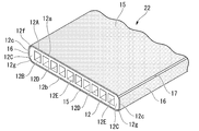
- FIG. 1 shows a cross-sectional structure of a flat tube 22 applied to the heat exchanger 11 shown in FIGS. 2 and 3, and the tube 22 is extruded formed by extruding aluminum or an aluminum alloy. It is made of a tube body 12 which is a material.
- the heat exchanger 11 of the first embodiment is used as a heat exchanger for indoor / outdoor units of a room air conditioner, an outdoor unit for HVAC (Heating Ventilating Air Conditioning), a heat exchanger for automobiles, and the like. It is an all-aluminum heat exchanger.
- the tube 22 shown in FIG. 1 shows a state before brazing, and shows a state in which the brazing composition layer is coated on the outer peripheral surface of the horizontally installed tube main body 12.
- the tube body 12 has a plurality of partition walls that partition the inside of the tube body 12 into a plurality of flow paths 12D, which are short side walls 12C and 12C in which the wide front wall 12A, the back wall 12B, and the left and right ends thereof are individually connected. It is composed of 12E.
- the plurality of flow paths 12D are all formed in a rectangular similar cross-sectional shape, and in the example shown in FIG. 1, 10 flow paths 12D are formed in the tube body.
- the tube body 12 shown in FIG. 1 is an example, and the width, thickness, flatness (ratio of width and thickness) of each part, and the shape and number of flow paths 12D can all be arbitrarily set. Can be done.
- the tube body 12 is formed in a flat shape having a wide flat front surface (upper surface) 12a and a back surface (lower surface) 12b, and flat short side surfaces 12c and 12c that individually connect both end sides thereof. ing. Further, in the tube main body 12, a corner portion 12f formed in an arc shape with a predetermined curvature is formed in a portion extending from the width direction end portion of the front surface 12a to the short side surface 12c, and the short side surface 12c is formed from the width direction end portion of the back surface 12b. A corner portion 12g formed in an arc shape with a predetermined curvature is also formed in the portion leading to.
- the portions of the short side surface 12c except for the upper and lower corner portions 12f and 12g are formed in a plane shape facing the front surface 12a and the back surface 12b at a substantially right angle.
- the overall shape of the short side surface 12c is not particularly limited, and may be a configuration in which the entire short surface is a curved surface or a shape composed of two planar inclined surfaces.
- a main brazing composition layer 15 composed of a coating film of a brazing composition having a composition described later is formed on the front surface 12a and the back surface 12b. Further, in the tube body 12, a sub-brazing composition layer 16 having a composition described later is formed on the short side surface 12c.
- the sub-brazing composition layer 16 is continuously formed on the short side surface 12c of the tube body 12 via an uncoated portion 17 having a constant width along the length direction of the tube body 12.
- the uncoated portion 17 is continuously formed in the length direction of the tube main body 12 at a position along the lower end portion and a position along the upper end portion of the short side surface 12c, respectively.
- the upper corner portion 12f and the lower corner portion 12g of the tube body 12 correspond to the uncoated portion 17.
- the width of the uncoated portion 17 is preferably 0.5 mm or more and 1 mm or less. In the form shown in FIG. 1, the widths of all the uncoated portions 17 are drawn to be the same, but the widths of all the uncoated portions 17 do not have to be the same and may vary within the above range. ..
- the brazed liquid composition in an undried state is obtained by supporting both side surfaces of the tube body 12 with the guide rollers 8a described later based on FIGS. 7 and 8.
- the coating film of the above may be transferred to the guide roller 8a side, and the coating film of the brazed liquid composition in the undried state may be peeled off.
- the coating film of the brazed liquid composition in an undried state is transferred to the guide roller 8a side, the guide roller 8a is contaminated.
- the width of the uncoated portion 17 exceeds 1 mm, a sufficient amount of the coating film of the brazing composition cannot be formed on the short side surface side of the tube body 12, resulting in poor bonding between the fin 13 and the tube body 12. There is a risk.
- the main brazing composition layer 15 and the sub-brazing composition layer 16 are composed of brazing compositions having the same composition, which will be described later, and their coating amounts (thicknesses) are different. The relationship between the coating amount and the thickness of the main brazing composition layer 15 and the sub-brazing composition layer 16 will be described in detail later.
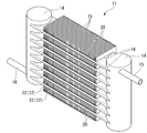
- FIG. 2 shows the overall structure of the heat exchanger 11 formed by brazing the plurality of tubes 22 shown in FIG. 1 to the header tube 14 and brazing the plurality of tubes 22 to the fins 13.
- the heat exchanger 11 is horizontally arranged between a pair of header pipes 14 arranged vertically separated from each other on the left and right sides and vertically spaced from each other between the pair of header pipes 14.
- a plurality of tubes 22 (tube body 12) joined at substantially right angles to the header tube 14 and a plurality of tubes brazed to the front surface 12a or the back surface 12b of the tube body 12 to dissipate heat to the outside air. It is equipped with fins 13.
- a supply pipe 15 for supplying a refrigerant to the tube 22 is connected to the upper end of one of the pair of left and right header pipes 14 via the header pipe 14.
- a recovery pipe 16 for recovering the refrigerant via the tube 22 is connected to the lower end of the other header pipe 14.
- the tube 22, fin 13, header pipe 14, supply pipe 15, and recovery pipe 16 are all made of aluminum or an aluminum alloy.
- FIG. 3 is a partial cross-sectional view of the heat exchanger 11 having a cross section taken along a plane orthogonal to the length direction of the tube 22.
- a plurality of (10 in this embodiment) refrigerant flow paths 12D arranged along the width direction are formed inside the tube main body 12 constituting the tube 22.
- a plurality of slit-shaped holes 19 having a shape corresponding to the cross-sectional shape of the tube 22 are formed horizontally in the fins 13 at predetermined intervals in the vertical direction. As shown in FIG. 3, these hole portions 19 are formed from the left end portion to the vicinity of the right end portion of the fin 13, and the innermost portion of the hole portion 19 is located slightly in front of the right end portion of the fin 13. .
- a tube 22 is fitted into each of these holes 19, and each tube 22 is fixed to a plurality of fins 13 by brazing.
- the length of the hole 19 formed in the fin 13 (horizontal length shown in FIG. 3) is slightly shorter than the width of the fin 13, and the short side surface of the tube 22 inserted into the hole 19 on one side in the width direction. 12c is inserted to the innermost part of the hole 19 and brazed.
- FIGS. 4 and 5 are partial cross-sectional views taken along the length direction of the tube 22 in the heat exchanger 11 shown in FIGS. 2 and 3, and FIG. 4 shows a state before brazing.
- FIG. 5 shows the state after brazing.
- a plurality of fins 13 are arranged in parallel along the length direction of the tube 22 (along the left-right direction of FIGS. 4 and 5), and the tube 22 is inserted into each hole 19.
- the plurality of fins 13 are arranged in parallel with each other at regular intervals.
- the fin 13 has a bent portion 20 that is bent to one side in the thickness direction of the fin 13 along the peripheral edge portion of the hole portion 19.
- the bent portion 20 is formed by a processing method such as burring.
- the tube 22 and the fin 13 are arranged so that the tube 22 skewers and penetrates a plurality of fins 13 arranged at regular intervals, and the fin 13 and the tube 22 are individually fixed by brazing.
- the gap between the bent portion 20 formed in the hole 19 of the fin 13 and the front surface or the back surface of the tube 22 is formed to be about 10 ⁇ m or less. If this gap is too large, the amount of wraparound of the melted brazing in the brazing step described later is insufficient, which may cause poor brazing.
- the fin 13 has a plate-shaped base material 3 and a hydrophilic film 1 coated on the first surface 3a and the second surface 3b of the base material 3.
- the base material 3 of the fin 13 is made of a pure aluminum alloy such as JIS1050 or an alloy mainly composed of JIS3003 aluminum alloy.
- the base material 3 may be made of an aluminum alloy in which Zn of about 2% by mass is added to a JIS3003 series aluminum alloy.
- the base material 3 of the fin 13 is formed by melting the aluminum alloy by a conventional method and passing through a hot rolling step, a cold rolling step, a pressing step and the like.
- the method for producing the base material 3 is not particularly limited in the present invention, and a known production method can be appropriately adopted.
- the aluminum alloy constituting the header pipe 14 is preferably an aluminum alloy based on an Al—Mn system.
- Mn 0.05 to 1.50%
- Cu 0.05 to 0.8%
- Zr 0.05 to 0.15% may be contained. it can.
- the tube 22 before brazing has a tube main body 12 and brazing composition layers 15 and 16 formed on the outer peripheral surface thereof.
- the tube body 12 is made of, for example, a pure aluminum alloy such as JIS1050 or an alloy mainly composed of JIS3003 aluminum alloy.
- Si 0.10 to 0.60%
- Fe 0.1 to 0.6% by mass
- Mn 0.1 to 0.6% by mass
- Ti 0.005 to 0.2% by mass
- Cu It is made of an aluminum alloy having less than 0.1% by mass and the balance consisting of aluminum and unavoidable impurities, and is produced by extruding these aluminum alloys.
- the main brazing composition layer 15 formed on the tube body 12 before brazing shown in FIGS. 1 and 4 is a coating film applied at least to the portion where the fins 3 are brazed and joined.
- the main brazing composition layer 15 contains Si powder: 1 to 5 g / m 2 , Zn-containing flux (for example, KZnF 3 ): 3 to 20 g / m 2 , and non-Zn-containing flux: 1 to 10 g / m. It is preferably composed of a dried product of a brazing coating film containing any one or more of m 2 and further containing a binder (for example, acrylic resin): 0.2 to 8.5 g / m 2.
- a binder for example, acrylic resin
- a brazing liquid composition is formed by blending an appropriate amount of solvent with these components, and the brazing liquid composition is applied to the front surface or the back surface of the tube body 12 to form a brazing liquid composition.
- the main brazing composition layer 15 is obtained by forming the coating film of the above and drying the coating film.
- the Si powder reacts with Al constituting the tube body 12 at the time of brazing to form a wax that joins the fin 3 and the tube body 12, but the Zn-containing flux and the Si powder are melted at the time of brazing to become a brazing liquid. .. Zn in the flux diffuses uniformly in this brazing liquid and spreads uniformly on the front surface and the back surface of the tube body 12.
- this Zn melt diffusion layer serves as a sacrificial anode layer, the corrosion resistance of the brazed portions on the front surface side and the back surface side of the tube body 12 can be improved.
- the sub-brazing composition layer 16 is also formed on the short side surface side of the tube body 12, Zn and Si contained in these brazing composition layers 16 are diffused, and the tube is formed.
- a sacrificial anode layer is also formed on the short side surface side of the main body 12.
- Si powder coating amount 1 to 5 g / m 2 > If the coating amount of Si powder is less than 1 g / m 2 , wax formation may be insufficient, and if the coating amount exceeds 5 g / m 2 , the melting amount of the tube body 12 increases and the tube body 12 The wall thickness of the is reduced, which is not preferable. Therefore, the content of the Si powder in the main brazing composition layer 15 is preferably 1 to 5 g / m 2 .
- the Zn-containing flux has the effect of forming Zn melt diffusion layers on the front surface side and the back surface side of the tube body 12 and improving pitting corrosion resistance during brazing. Further, at the time of brazing, the oxide film on the outer surface of the tube 3 is destroyed, the spread and wetting of the wax are promoted, and the brazing property is improved. Since this Zn-containing flux has a higher activity than the Zn-free flux, good brazing property can be obtained even if a relatively fine Si powder is used.
- the Zn-containing flux one or more of KZnF 3 , ZnF 2 , and ZnCl 2 can be used.
- a non-Zn-containing flux may be added to the Zn-containing flux.
- Flux of the fluoride-based flux or potassium fluoroaluminate-based way of non-Zn-containing flux is a flux mainly composed of KAlF 4, various compositions are known plus additives. Examples thereof include those having a composition of K 3 AlF 6 + KAlF 4 (K 1-3 AlF 6-4 ), Cs (x), K (y), F (z), and the like.
- a fluoride-based flux for example, a potassium fluoroaluminate-based flux
- a fluoride-based flux for example, a potassium fluoroaluminate-based flux
- a fluoride-based flux for example, a potassium fluoroaluminate-based flux
- a fluoride-based flux for example, a potassium fluoroaluminate-based flux
- ⁇ Flux coating amount 3 to 20 g / m 2 > If the coating amount of the Zn-containing flux is less than 3 g / m 2 , the potential difference when the heat exchanger 11 is used becomes low, and the sacrificial effect may not be exhibited. Further, since the surface oxide film of the tube body 12 is not sufficiently destroyed and removed, brazing failure may occur. On the other hand, if the coating amount exceeds 20 g / m 2 , the potential difference becomes excessive, the corrosion rate increases, and the anticorrosion effect due to the presence of the Zn melt diffusion layer may be shortened. Therefore, it is preferable that the coating amount of the Zn-containing flux is 3 to 20 g / m 2 . As the Zn-containing flux, KZnF 3 can be used as an example. The above-mentioned non-Zn-containing flux can be added in addition to the Zn-containing flux.
- the brazing composition layer 15 can contain a binder in addition to the Si powder and the Zn-containing flux.
- Acrylic resin can be mentioned as an example of a binder.
- the binder has the function of fixing the Si powder and the Zn-containing flux necessary for forming the Zn melt diffusion layer to the front surface and the back surface of the tube 22, but if the amount of the binder applied is less than 0.2 g / m 2, it is brazed. Occasionally, Si powder or Zn flux may fall off from the tube body 12, and a uniform Zn melt diffusion layer may not be formed.
- the amount of the binder applied is preferably 0.2 to 8.5 g / m 2 .
- the binder is usually transpired by heating during brazing.
- the method for forming the brazing composition layer 15 composed of Si powder, flux and binder is not particularly limited in this embodiment, and the spray method, shower method, flow coater method, bar coater method, roll coater method, and brushing method are used. It can be carried out by an appropriate method such as a coating method, a dipping method, or an electrostatic coating method.
- the sub-brazing composition layer 16 formed on the side surface side of the tube main body 12 shown in FIG. 1 is basically made of the same material as the material constituting the main brazing composition layer 15. That is, it contains one or more of Si powder, Zn-containing flux, and non-Zn-containing flux, and further contains a binder. Alternatively, it is composed of a composition containing one or more of Si powder, Zn-containing flux and non-Zn-containing flux, and further adding a solvent to a binder. However, it is preferable that the sub-brazing composition layer 16 is formed in a coating amount (thickness) 1 to 5 times the coating amount (thickness) of the main brazing composition layer 15.
- the coating amount of the sub-brazing composition layer 16 is less than 1 times the coating amount of the main brazing composition layer 15, the brazing property and corrosion resistance may be insufficient.
- the coating amount of the secondary brazing composition layer 16 exceeds 5 times the coating amount of the main brazing composition layer 15, the amount of brazing material (Si amount) between the fin 13 and the tube body 12 becomes too large.
- the corrosion rate of the tube body 12 and the fins 13 becomes too high, and there is a possibility that problems such as through holes are likely to occur in the tube body 12 or the fins 13 due to corrosion.
- the sub-brazing composition layer 16 is formed on the short side surface of the tube body 12. At the time of brazing, the sub-brazing composition layer 16 melts and solidifies, and the short side surface side of the tube body 12 is brazed and fixed to the innermost side of the hole 19 of the fin 13. Without the sub-brazing composition layer 16, the fixing force for brazing and fixing the short side surface side of the tube body 12 to the fins 13 is insufficient.
- a configuration in response to the demand for miniaturization and compactification of the outdoor unit, a configuration is known in which a part of the heat exchanger is bent into an L-shape in a plan view and housed in the outdoor unit.
- a part of the heat exchanger is bent into an L shape in a plan view in this way, if the force for brazing and fixing the short side surface side of the tube body 12 to the innermost side of the hole 19 of the fin 13 is insufficient. A part of the plurality of fins 13 may fall down at the bent portion. If the sub-brazing composition layer 16 provided on the short side surface side of the tube body 12 has a sufficient thickness, the brazing fixing force of the fins 13 can be sufficiently secured.
- the tube body 12 can be bent without causing the fins to fall.
- the number of refrigerant flow paths in the tube body 12 is reduced to adopt a structure having a low flatness. ..
- FIG. 4 shows a vertical cross section of the tube body 12 inserted into the hole 19 of the fin 13, and the main brazing composition layer 15 of the tube body 12 faces the tube body 12 of the bent portion 20 of the fin 13. It is located between the portion to be brazed (opposing surface 20a) and the tube body 12.
- the main brazing composition layer 15 is cooled after heating at around 600 ° C. (brazing heating) to solidify in a state of being filled between the facing surface 20a and the tube body 12, and as shown in FIG.
- a fillet 15A is formed in the fin 13 and the tube body 12 is joined.
- the sub-brazing composition layer 16 formed on the short side surface side of the tube body 12 and its corner portion becomes a fillet after brazing, and the short side surface side of the tube body 12 is placed on the innermost side of the hole portion 19. Join.
- the main brazing composition layer 15 is formed in a region in contact with the fins 13, that is, on the front surface 12a and the back surface 12b of the tube body 12. Further, Si and Zn contained in the main brazing composition layer 15 before brazing diffuse to the tube body 12 side at the brazing temperature, and the surface layer portion of the front and back surfaces of the tube body 12 contains Si and Zn. Form an anode layer. Further, Si and Zn contained in the sub-brazing composition layer 16 are also diffused to the short side surface side of the tube body 12 at the time of brazing, and a sacrificial anode layer containing Si and Zn is formed in these portions.
- a sacrificial anode layer can be formed on the entire circumference of the tube body 12 in the portion where the sub-brazing composition layer 16 is provided. Therefore, the corrosion resistance on the short side surface of the tube body 12 can be improved.
- the method of forming the main brazing composition layer 15 and the sub-brazing composition layer 16 on the tube body 12 and the method of drying them will be described below.
- the method for forming the main brazing composition layer 15 composed of Si powder, flux, and binder is not particularly limited in this embodiment.
- a paint obtained by adding a solvent to Si powder, a flux, and a binder to form a brazed liquid composition may be applied by the following method and dried.
- the coating can be applied by an appropriate method such as a spray method, a shower method, a flow coater method, a bar coater method, a roll coater method, a brush coating method, a dipping method, or an electrostatic coating method.
- the main brazing composition layer 15 can be formed in a required range on the front surface 12a and the back surface 12b of the tube body 12 with a required coating amount.
- the main brazing composition layer 15 can be formed on substantially the entire surface of the front surface 12a and the back surface 12b of the tube body 12.
- the brazed liquid composition used here is the above-mentioned Si powder, a Zn-containing flux (for example, KZnF 3 ), and a binder (for example, an acrylic resin) to which a required amount of solvent is added to obtain a viscosity desirable for an inkjet method.
- a Zn-containing flux for example, KZnF 3
- a binder for example, an acrylic resin
- the above-mentioned Si powder, Zn-containing flux (for example, KZnF 3 ), non-Zn-containing flux, and binder (for example, acrylic resin) are added with a required amount of solvent to obtain a liquid having a viscosity desirable for the inkjet method.
- It means a liquid composition with a wax.
- it means a brazed liquid composition obtained by adding a necessary amount of solvent to the above-mentioned Si powder, a non-Zn-containing flux, and a binder (for example, an acrylic resin) to obtain a liquid having a viscosity desirable for an inkjet method.
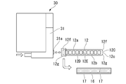
- the coating device 30 shown in FIG. 6 is a piezo injection type coating device having a nozzle 31a in the head portion 31.
- the brazing liquid composition contained in a tank (not shown) is guided to the head portion 31 and head portion 31. It is configured so that a predetermined amount of brazed liquid composition can be injected from the tip of the nozzle 31a using a piezo type injector built in the nozzle 31a.
- a piezo type injector A piezo element that expands and contracts when a voltage is applied is provided in a part of the liquid chamber, and the liquid in the liquid chamber is liquid from the head part connected to a part of the liquid chamber according to the expansion and contraction of the piezo element. It is a coating device that can be sprayed as drops.
- the coating device 30 is provided with a head moving mechanism (not shown) that supports the head portion 31 so as to be movable in a predetermined range in a three-dimensional direction (XYZ direction) at high speed, and the purpose is to respond to the movement of the head portion 31.
- a coating film of a brazed liquid composition having a desired thickness can be formed in the range of.
- the tube body is arranged in front of the nozzle 31a by injecting droplets of the brazed liquid composition at a discharge cycle of 100 to 1200 Hz with a discharge opening diameter of 0.3 mm of the nozzle 31a.
- a coating film of a brazed liquid composition having a thickness of about 1 ⁇ m to 50 ⁇ m can be continuously formed on the short side surface 12c of 12.
- this coating device 30 is used to apply a coating film of a brazed liquid composition on the short side surface side of the tube body 12 along the length direction of the tube body via one or more uncoated portions 17.
- the brazing composition coating film 16a can be continuously formed.
- an end face coating device manufactured by SSI Japan Co., Ltd. can be used.
- FIG. 6 the description of the main brazing composition layer 15 formed in the previous step on the upper and lower surfaces of the tube main body 12 is omitted, and only the sub-brazing composition layer 16 is shown.
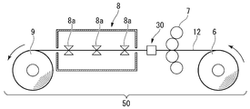
- FIG. 7 shows a winding roller 6 capable of unwinding the tube body 12, a coater 7 capable of applying the brazing liquid composition, a coating device 30, and a drying furnace 8 for drying the coating film of the brazing liquid composition.
- the unwinding roller 6 is a roller capable of winding and holding the tube body 12 having a required length, and unwinding the tube body 12 as needed.
- the coater 7 is composed of a plurality of rolls combined vertically, and a liquid brazing composition contained in a tank (not shown) is pumped up by the plurality of rolls, and the front surface and the back surface of the tube body 12 passing between the upper and lower rolls.
- a coating device capable of forming a coating film of a brazing liquid composition (main brazing composition coating film).
- the coating device 30 of this example includes two head portions 31 provided with the nozzles 31a described above, and coats the desired secondary brazing composition on both short sides of the tube body 12 while the tube body 12 passes through the coating device 30.
- This is a coating device capable of continuously forming the film 16a via the uncoated portion 17.
- the drying furnace 8 has a plurality of drum-shaped guide rolls 8a and a heater (not shown) in the furnace, and may be applied to the tube body 12 while the tube body 12 is being conveyed along the plurality of guide rolls 8a.
- a drying furnace capable of heating and drying a coating film of a liquid composition to fix it.
- paired drum-shaped guide rolls 8a are arranged so as to be separated from each other from the inlet side to the outlet side of the drying furnace 8.
- the tube body 12 can be conveyed while being horizontally supported while sandwiching the tube body 12 between the guide rolls 8a arranged on the left and right.
- the brazing composition coating film applied to the front surface and the back surface of the tube body 12 and both short side surfaces is omitted, and only the approximate shape of the tube body 12 is drawn.
- the guide rolls 8a and 8a horizontally convey the tube body 12 while being in contact with both side surfaces of the tube body 12. Therefore, the sub-brazing composition coating film 16a formed on both short side surfaces 12c of the tube body 12 may come into contact with the peripheral surfaces of the guide rolls 8a and 8a and be transferred or peeled off to the guide roll side.
- the sub-brazing composition coating film 16a is formed on both short side surfaces of the tube body 12 via the uncoated portion 17 having a width of 0.5 mm or more and 1 mm or less, the sub-brazing composition coating film is applied.
- the film 16a and the peripheral surfaces of the guide rolls 8a and 8a are no longer in contact with each other, and the sub-brazing composition coating film 16a is not peeled off.
- the guide roll 8a horizontally conveys the tube body 12 while only a part of the inner peripheral surface 8b is in contact with the lower end of the short side surface of the tube body 12 in the horizontal state. That is, on the short side surfaces 12c on both sides of the tube body 12 shown in FIG. 8, only the corner portion of the lower end of the short side surface contacts the inner peripheral surface 8b of the guide roll 8a. Therefore, strictly speaking, if the uncoated portion 17 is formed only on the lower end portion of the short side surface 12c, the object may be achieved.
- the contact position between the tube body 12 and the inner peripheral surface 8b of the guide roll 8a is slightly different during transportation. It is preferable that the uncoated portion 17 is formed on the lower portion and the upper portion of the short side surface 12b in consideration of moving up and down and slightly moving back and forth.
- the coating film of the main brazing liquid composition and the coating film 16a of the secondary brazing liquid composition are gradually dried, and the main brazing composition layer 15 and the secondary brazing composition layer are gradually dried. 16 is formed.
- the main brazing composition layer 15 and the sub-brazing composition layer 16 are fixed to the tube body 12 and adhere to the tube body 12, so that these composition layers are difficult to peel off.
- the tubes 22 are inserted into the holes 19 of the fins 13 installed in parallel and fitted, and assembled in a state close to FIG. Braze.
- Brazing is performed by performing a brazing step of heating the brazing composition layers 15 and 16 to a temperature equal to or higher than the melting point, for example, 580 to 620 ° C. in a heating furnace for about several minutes.
- the brazing composition layers 15 and 16 are melted into a brazing liquid.
- This brazing liquid flows into the gap between the tube body 12 and the bent portion 20 of the fin 13, and fills these gaps.
- the wax solution described above also flows into a gap on the short side surface side of the tube body 12 fitted at the innermost position of the hole 19 to fill this gap.
- the waxy liquid solidifies and a fillet 15A is formed.
- the tube body 12 and the fins 13 are brazed and joined by these fillets 15A.
- Si and Zn in the flux are diffused by brazing, and a Zn molten diffusion layer (sacrificial anode layer) is formed on the short side surface in addition to the front and back surfaces of the tube body 12. It is formed.
- the brazing composition layer 16 is formed after the main brazing composition layer 15 is formed, but the order in which these are formed may be any first, and these may be formed at the same time. ..
- the brazing composition layer 16 is formed on the short side surface side by the coating device 30, and then the main brazing composition layer 15 is formed on the front and back surfaces using a bar coater or a roll coater. May be formed.
- the main brazing composition layer 15 is formed on the front and back surfaces by using a bar coater or a roll coater, and the brazing composition is continuously formed on the short side surface side by the coating device 30 provided adjacent to the bar coater or the roll coater.
- the material layer 16 may be formed. After forming these composition layers on a long tube body 12 made of extruded material, the tube body 12 is cut to a required length to obtain a brazing tube 22 for a heat exchanger.
- the heat exchanger 11 can be configured by brazing a tube 22 provided with the brazing composition layers 15 and 16 in combination with a plurality of fins 13.
- the brazing composition layer 15 provided on the front and back sides of the tube body 12 can reliably braze the fins 13 on the front and back sides of the tube body 12.
- the brazing composition layer 16 provided on the short side surface side of the tube body 12 can reliably braze the short side surface side of the tube body 12 to the fins 13. Therefore, the entire tube body 12 can be reliably brazed to the fins 13 with sufficient bonding strength. That is, high quality brazing joints can be made in the heat exchanger 11.
- Zn can be diffused not only on the front surface side and the back surface side of the tube 12 but also on the short side surface side, and the entire circumference of the tube 12 is sacrificed.
- An anode layer can be formed.
- the width of the uncoated portion 17 is set to the minimum required of 0.5 mm or more and 1 mm or less, the brazing property is not adversely affected, and a sacrificial anode layer is formed by Zn diffusion from both sides of the uncoated portion 17. Therefore, it is possible to provide the heat exchanger 11 having good corrosion resistance by appropriately controlling the corrosion rate by the diffusion progress of Zn with respect to the uncoated portion 17 as well as the coated portion.
- the portion where the sacrificial anode layer is formed proceeds to corrode not as pitting corrosion but as surface corrosion, it is possible to provide a structure in which the tube body 12 is less likely to have through holes due to corrosion. Further, by forming the sacrificial anode layer on the entire circumference of the tube body 12, it is possible to provide the heat exchanger 11 having an anticorrosive structure capable of suppressing corrosion of the brazed portion adjacent to the sacrificial anode layer.
- a brazing composition layer containing Si powder and a Zn-containing flux may be formed on both the front surface / back surface side and the short side surface of the tube 12. Further, a brazing composition layer containing Si powder, Zn-containing flux and non-Zn-containing flux may be formed on both the front surface / back surface side and the short side surface of the tube 12.
- composition layer containing a non-Zn-containing flux may be formed on both the front surface / back surface side and the short side surface of the tube 12. Further, a composition layer containing a Zn-containing flux may be formed on both the front surface / back surface side and the short side surface of the tube 12.
- a composition layer containing a Zn-containing flux and a non-Zn-containing flux may be formed on both the front surface / back surface side and the short side surface of the tube 12.
- the brazing material can be supplied to the joint portion by using a brazing sheet, a brazing rod, or the like.
- a brazing composition layer containing Si powder and a Zn-containing flux may be formed on the front and back surfaces of the tube 12, and a composition layer containing a Zn-containing flux may be formed on the short side surface of the tube 12. Further, a brazing composition layer containing Si powder, Zn-containing flux and non-Zn-containing flux is formed on the front and back surfaces of the tube 12, and a composition containing Zn-containing flux and non-Zn-containing flux on the short side surface of the tube 12. Layers may be formed.
- a composition layer containing a non-Zn-containing flux may be formed on the front surface and the back surface side of the tube 12, and a brazing composition layer containing a Si powder and a Zn-containing flux may be formed on the short side surface of the tube 12. Further, a composition layer containing a non-Zn-containing flux is formed on the front surface and the back surface side of the tube 12, and a brazing composition layer containing Si powder, a Zn-containing flux and a non-Zn-containing flux is formed on the short side surface of the tube 12. You may.
- a composition layer containing a Zn-containing flux may be formed on the front and back surfaces of the tube 12, and a brazing composition layer containing a Si powder and a Zn-containing flux may be formed on the short side surface of the tube 12. Further, a brazing composition containing a Zn-containing flux and a non-Zn-containing flux on the front and back surfaces of the tube 12 and a Si powder, a Zn-containing flux and a non-Zn-containing flux on the short side surface of the tube 12. Layers may be formed.
- a flat multi-hole tube made of an aluminum alloy containing Si: 0.3 to 0.5% by mass and Mn: 0.2 to 0.4% by mass and composed of unavoidable impurities and Al was prepared.
- This flat multi-hole tube has a width of 17 mm, a thickness of 1.5 mm, and a corner portion having a radius of curvature of 0.3 mm at the corner portion of the boundary between the front and back surfaces and the short side surface.
- the coating film was Si powder: 3 g / m 2 , Zn-containing flux (KZnF 3 ): 6 g / m 2 , and acrylic as a binder.
- the system resin was applied so as to have a ratio of 1 g / m 2 .
- the coating film was Si powder: 0.9 g / m 2 , Zn-containing flux (KZnF 3 ): 2.9 g / m 2 , and acrylic resin as a binder: 0.2 g / m 2 . It was applied in proportion.
- the coating film has a ratio of Si powder: 1 g / m 2 , Zn-containing flux (KZnF 3 ): 3 g / m 2 , and acrylic resin as a binder: 0.2 g / m 2.
- the coating film has a ratio of Si powder: 1 g / m 2 , Zn-containing flux (KZnF 3 ): 3 g / m 2 , and acrylic resin as a binder: 0.2 g / m 2.
- the coating film has a ratio of Si powder: 5 g / m 2 , Zn-containing flux (KZnF 3 ): 20 g / m 2 , and acrylic resin as a binder: 8.5 g / m 2.
- the coating film was Si powder: 5.2 g / m 2 , Zn-containing flux (KZnF 3 ): 20.2 g / m 2 , and acrylic resin as a binder: 8.6 g / m 2 . It was applied in proportion.
- Examples 18 to 34, 103 to 119 and Comparative Examples 5 to 8 and 25 to 28 Si powder, Zn-containing flux (KZnF 3 ), and non-Zn-containing flux were used on the front and back surfaces of the flat multi-hole tube using a roll coater. (K 1-3 AlF 6-4 ), a brazing liquid composition in which an acrylic resin as a binder was dispersed in a solvent was applied.
- the coating film was Si powder: 3 g / m 2 , Zn-containing flux (KZnF 3 ): 5 g / m 2 , non-Zn-containing flux.
- the coating film was Si powder: 1 g / m 2 , Zn-containing flux (KZnF 3 ): 3 g / m 2 , non-Zn-containing flux (KZnF 3 ): 1 g / m 2 , acrylic as a binder.
- the system resin was applied so as to have a ratio of 0.2 g / m 2 .
- the coating film was Si powder: 5 g / m 2 , Zn-containing flux (KZnF 3 ): 20 g / m 2 , non-Zn-containing flux (KZnF 3 ): 10 g / m 2 , and acrylic as a binder.
- the coating was applied so as to have a ratio of 8.5 g / m 2 .
- the coating film was Si powder: 5.1 g / m 2 , Zn-containing flux (KZnF 3 ): 20.2 g / m 2 , and non-Zn-containing flux (KZnF 3 ): 10.1 g / m. 2.
- Acrylic resin as a binder 8.6 g / m 2 was applied.
- a non-Zn-containing flux (K 1-3 AlF 6-4 ) was used on the front surface and the back surface of the flat multi-hole tube using a roll coater.
- a liquid composition in which an acrylic resin as a binder was dispersed in a solvent was applied.
- the coating film was a non-Zn-containing flux (K 1-3 AlF 6-4 ): 9 g / m 2 , as a binder. Acrylic resin of 1 g / m 2 was applied.
- the coating film was applied so as to have a non-Zn-containing flux (KZnF 3 ): 0.8 g / m 2 and an acrylic resin as a binder: 0.2 g / m 2 . ..
- the coating film was applied at a ratio of non-Zn-containing flux (KZnF 3 ): 1 g / m 2 and acrylic resin as a binder: 0.2 g / m 2 .
- Example 50 the coating film was applied at a ratio of non-Zn-containing flux (KZnF 3 ): 10 g / m 2 and acrylic resin as a binder: 8.5 g / m 2 .
- KZnF 3 non-Zn-containing flux
- acrylic resin as a binder 8.5 g / m 2 .
- Example 51,135,153 coatings, non-Zn-containing flux (KZnF 3): 10.4g / m 2, an acrylic resin as a binder: was coated to a rate of 8.6 g / m 2 ..
- Example 52 to 68, 154 to 170 and Comparative Examples 13 to 16, 37 to 40 a roll coater was used on the front surface and the back surface of the flat multi-hole tube, and a Zn-containing flux (KZnF 3 ) and an acrylic resin as a binder were used.
- a Zn-containing flux (KZnF 3 ) and an acrylic resin as a binder were used.
- the coating film was made of Zn-containing flux (KZnF 3 ): 9 g / m 2
- acrylic resin as a binder 1 g / m 2 . It was applied in proportion.
- the flux was applied so as to have a ratio of Zn-containing flux (KZnF 3 ): 2.8 g / m 2 and acrylic resin as a binder: 0.2 g / m 2 .
- the flux was applied so as to have a ratio of Zn-containing flux (KZnF 3 ): 3 g / m 2 and acrylic resin as a binder: 0.2 g / m 2 .
- the flux was applied so as to have a ratio of Zn-containing flux (KZnF 3 ): 20 g / m 2 and acrylic resin as a binder: 8.5 g / m 2 .
- an acrylic resin as a binder was coated to a rate of 8.6 g / m 2.
- Examples 69 to 85, 171 to 187 and Comparative Examples 17 to 20, 41 to 44 Zn-containing flux (KZnF 3 ) and non-Zn-containing flux (K) were used on the front and back surfaces of the flat multi-hole tube. 1-3 AlF 6-4 ), a liquid composition in which an acrylic resin as a binder was dispersed in a solvent was applied.
- the coating film was Zn-containing flux (KZnF 3 ): 5 g / m 2 , non-Zn-containing flux (K 1-3 AlF 6-).
- the coating film had a Zn-containing flux (KZnF 3 ): 2.9 g / m 2 , a non-Zn-containing flux: 0.9 g / m 2 , and an acrylic resin as a binder: 0.2 g / m. It was applied so as to have a ratio of 2 .
- the coating film had a ratio of Zn-containing flux (KZnF 3 ): 3 g / m 2 , non-Zn-containing flux: 1 g / m 2 , and acrylic resin as a binder: 0.2 g / m 2 . It was applied so as to become.
- the coating film had a ratio of Zn-containing flux (KZnF 3 ): 20 g / m 2 , non-Zn-containing flux: 10 g / m 2 , and acrylic resin as a binder: 8.5 g / m 2 . It was applied so as to become.
- Example 85 187, the coating film, the Zn-containing flux (KZnF 3): 20.2g / m 2, the non-Zn containing flux: 10.2 g / m 2, an acrylic resin as a binder: 8.6 g / m It was applied so as to have a ratio of 2 .
- a coating film of the brazed liquid composition was intermittently continuously applied to both short sides of the flat multi-hole tube via an uncoated portion using an end face coating device manufactured by SSI Japan Co., Ltd. Formed.
- the discharge opening diameter of the inkjet coating device was 0.3 mm, and the discharge cycle was set to 600 to 1200 Hz.
- the short side surface of the flat multi-hole tube is compared with the example shown in Table 1 described later while moving the long extruded flat multi-hole tube in the length direction at a moving speed of 1.0 m / s.
- a coating film composed of a brazed liquid composition was continuously formed through an uncoated portion having a length (width) of 0.4 mm to 1.1 mm.
- the amount of coating film applied to the short side surface is 0.8 times, 1 time, 3 times, 5 times, and 5.5 times that of the front and back surfaces, and the Si powder: 2.4, 3, 9, 15, 16.5 g / m 2 , Zn-containing flux (KZnF 3 ): 4.8, 6, 18, 30, 33 g / m 2 , acrylic resin as binder: 0.8, 1, 3, 5 , 5 It was applied at a ratio of .5 g / m 2 .
- the applied liquid composition for brazing includes Si powder (D (99) particle size 10 ⁇ m), Zn-containing flux (KZnF 3 powder: D (50) particle size 2.0 ⁇ m), acrylic resin binder, and 3- as a solvent. It is a brazed liquid composition consisting of a mixture of methoxy-3-methyl-1-butanol and isopropyl alcohol.
- Examples 18 to 34, 137 to 153, 171 to 187 and Comparative Examples 5 to 8, 33 to 36, 41 to 44, Si powder and Zn-containing flux (KZnF 3) were formed on the short side surface of the flat multi-hole tube by the above method.
- Non-Zn-containing flux K 1-3 AlF 6-4
- waxed liquid composition in which an acrylic resin as a binder is dispersed in a solvent (mixture of 3-methoxy-3-methyl-1-butanol and isopropyl alcohol). I applied the thing.
- Si powder 2.4, 3, 9, 15, 16.5 g / m 2
- Zn-containing flux KZnF 3
- Non-Zn-containing flux K 1-3 AlF 6-4
- an acrylic resin as a binder was coated to a ratio of 1 g / m 2.
- the applied liquid composition for brazing includes Si powder (D (99) particle size 10 ⁇ m), Zn-containing flux (KZnF 3 powder: D (50) particle size 2.0 ⁇ m), and non-Zn-containing flux (K 1-3 AlF).
- 6-4 powder A brazed liquid composition comprising a D (50) particle size of 2.0 ⁇ m), an acrylic resin binder, and a mixture of 3-methoxy-3-methyl-1-butanol as a solvent and isopropyl alcohol.
- a non-Zn-containing flux (K 1-3 AlF 6-4 ) and an acrylic resin as a binder are used as a solvent (3) on the short side surface of the flat multi-hole tube by the above method.
- a liquid composition dispersed in a mixture of -methoxy-3-methyl-1-butanol and isopropyl alcohol) was applied.
- the coating film is a non-Zn-containing flux (K 1-3 AlF 6) when the amount applied to the short side surface is 0.8 times, 1 time, 3 times, 5 times, and 5.5 times that of the front and back surfaces.
- the applied liquid composition for brazing is a non-Zn-containing flux (K 1-3 AlF 6-4 powder: D (50) particle size 2.0 ⁇ m), an acrylic resin binder, and 3-methoxy-3-methyl as a solvent.
- a brazed liquid composition consisting of a mixture of -1-butanol and isopropyl alcohol.
- a Zn-containing flux (KZnF 3 ) and an acrylic resin as a binder are used as a solvent (KZnF 3 ) on the short side surface of the flat multi-hole tube by the above method.
- a liquid composition dispersed in a mixture of 3-methoxy-3-methyl-1-butanol and isopropyl alcohol) was applied.
- the coating film has a Zn-containing flux (KZnF 3 ): 7.2 when the amount applied to the short side surface is 0.8 times, 1 time, 3 times, 5 times, and 5.5 times that of the front and back surfaces.
- the applied liquid composition for brazing includes a Zn-containing flux (KZnF 3 powder: D (50) particle size 2.0 ⁇ m), an acrylic resin binder, 3-methoxy-3-methyl-1-butanol as a solvent, and isopropyl alcohol. It is a brazing liquid composition consisting of a mixture of.
- Zn-containing flux (KZnF 3 ) and non-Zn-containing flux (K 1-3 ) were formed on the short side surface of the flat multi-hole tube by the above method.
- AlF 6-4 a brazing liquid composition in which an acrylic resin as a binder was dispersed in a solvent (a mixture of 3-methoxy-3-methyl-1-butanol and isopropyl alcohol) was applied.
- the coating film has a Zn-containing flux (KZnF 3 ): 4, 5 when the amount applied to the short side surface is 0.8 times, 1 time, 3 times, 5 times, and 5.5 times that of the front and back surfaces.
- the applied liquid composition for brazing includes a Zn-containing flux (KZnF 3 powder: D (50) particle size 2.0 ⁇ m) and a non-Zn-containing flux (K 1-3 AlF 6-4 powder: D (50) particle size. 0 ⁇ m), a brazed liquid composition comprising an acrylic resin binder, a mixture of 3-methoxy-3-methyl-1-butanol as a solvent and isopropyl alcohol.
- the coating amount of the liquid composition on the short side surface in Examples 1 to 187 and Comparative Examples 1 to 44 is shown in Tables 1 to 8 as a multiple of the coating amount on the front surface and the back surface.
- the flat multi-hole tube is introduced into a drying oven equipped with 12 pairs of guide rolls 8a as shown in FIGS. 7 and 8, and while passing through the drying oven.
- a brazing tube having a brazing composition layer on the front and back surfaces and short side surfaces is manufactured by carrying out the drying process under the above conditions, the guide roller in the drying furnace is visually observed after the drying process is completed, and the guide roller is used.
- the paint of the brazed liquid composition adhered to the peripheral surface of the surface, it was judged that there was paint, and when the paint did not adhere, it was judged that there was no paint and evaluated.
- a brazing tube coated with a brazing composition layer was fitted into each hole formed in the fins arranged in parallel as described above, and a heat exchanger mini-core body was assembled.
- the assembled heat exchanger mini-core body was heated to 600 ° C. for 3 minutes in a brazing furnace in a nitrogen gas atmosphere and brazed.
- a sub-brazing composition layer is intermittently continuously provided on the short side surface of the flat multi-hole tube along the length direction of the tube via an uncoated portion.
- the paint of the brazed liquid composition adheres to the guide roller side while ensuring excellent brazing bondability by providing an uncoated portion having a length (width) of 0.5 mm or more and 1.0 mm or less. I was able to realize a configuration that does not allow it.
- a sub-brazing composition layer in a coating amount range of 1 to 5 times the coating amount of the main brazing composition layer coated on the front and back surfaces of the flat multi-hole tube is formed on the short side surface of the flat multi-hole tube.
- a heat exchanger having a structure in which the paint of the brazing liquid composition does not adhere to the guide roller side, has excellent brazing property, and has good corrosion resistance can be obtained.
- Comparative Examples 1, 5, 9, 13, 17, 21, 25, 29, 33, 37 and 41 shown in Tables 7 to 8 the length (width) of the uncoated portion was reduced to 0.4 mm.
- Comparative Examples 2, 6, 10, 14, 18, 22, 26, 30, 34, 38, and 42 shown in Tables 7 to 8 are samples in which the length of the uncoated portion is increased to 1.1 mm, but guides are provided. No transfer of the brazing liquid paint to the roller occurred, but the length (width) of the uncoated portion was large, so that both the brazing property and the corrosion resistance were deteriorated.
- brazing tube that prevents the brazing composition on the short side surface side from peeling off in a flat tube body and ensures excellent corrosion resistance and brazing property on the short side surface side of the tube body. become able to.
Landscapes
- Engineering & Computer Science (AREA)
- Physics & Mathematics (AREA)
- Mechanical Engineering (AREA)
- Thermal Sciences (AREA)
- General Engineering & Computer Science (AREA)
- Chemical & Material Sciences (AREA)
- Geometry (AREA)
- Materials Engineering (AREA)
- Metallurgy (AREA)
- Organic Chemistry (AREA)
- Heat-Exchange Devices With Radiators And Conduit Assemblies (AREA)
- Details Of Heat-Exchange And Heat-Transfer (AREA)
Abstract
L'invention concerne un tube de brasage (22) constitué d'aluminium ou d'un alliage d'aluminium et comprenant un corps principal de tube plat (12) ayant une surface avant (12a), une surface arrière (12b) et des surfaces côté court (12c), une couche de composition de brasage (16) étant formée sur les surfaces côté court (12c). La couche de composition de brasage est formée en continu, dans la direction longitudinale du corps principal de tube (12), sur les surfaces côté court (12c), au moins une section non revêtue (17) étant interposée entre ces dernières ; et la largeur de la section non revêtue (17), qui suit la direction longitudinale du corps principal de tube, est comprise entre 0,5 et 1 mm.
Priority Applications (1)
| Application Number | Priority Date | Filing Date | Title |
|---|---|---|---|
| JP2021509579A JP7198346B2 (ja) | 2019-03-26 | 2020-03-26 | ろう付け用チューブおよびその製造方法と熱交換器 |
Applications Claiming Priority (2)
| Application Number | Priority Date | Filing Date | Title |
|---|---|---|---|
| JP2019-058261 | 2019-03-26 | ||
| JP2019058261 | 2019-03-26 |
Publications (1)
| Publication Number | Publication Date |
|---|---|
| WO2020196740A1 true WO2020196740A1 (fr) | 2020-10-01 |
Family
ID=72611077
Family Applications (1)
| Application Number | Title | Priority Date | Filing Date |
|---|---|---|---|
| PCT/JP2020/013631 Ceased WO2020196740A1 (fr) | 2019-03-26 | 2020-03-26 | Tube de brasage, procédé de fabrication d'un tel tube de brasage et échangeur de chaleur |
Country Status (2)
| Country | Link |
|---|---|
| JP (1) | JP7198346B2 (fr) |
| WO (1) | WO2020196740A1 (fr) |
Citations (2)
| Publication number | Priority date | Publication date | Assignee | Title |
|---|---|---|---|---|
| WO2013161792A1 (fr) * | 2012-04-27 | 2013-10-31 | 三菱電機株式会社 | Echangeur de chaleur, méthode de production de celui-ci et dispositif à cycle de réfrigération |
| JP2019011922A (ja) * | 2017-06-30 | 2019-01-24 | 三菱アルミニウム株式会社 | 耐食性に優れたアルミニウム合金製熱交換器の製造方法およびアルミニウム合金製熱交換器 |
-
2020
- 2020-03-26 JP JP2021509579A patent/JP7198346B2/ja active Active
- 2020-03-26 WO PCT/JP2020/013631 patent/WO2020196740A1/fr not_active Ceased
Patent Citations (2)
| Publication number | Priority date | Publication date | Assignee | Title |
|---|---|---|---|---|
| WO2013161792A1 (fr) * | 2012-04-27 | 2013-10-31 | 三菱電機株式会社 | Echangeur de chaleur, méthode de production de celui-ci et dispositif à cycle de réfrigération |
| JP2019011922A (ja) * | 2017-06-30 | 2019-01-24 | 三菱アルミニウム株式会社 | 耐食性に優れたアルミニウム合金製熱交換器の製造方法およびアルミニウム合金製熱交換器 |
Also Published As
| Publication number | Publication date |
|---|---|
| JP7198346B2 (ja) | 2022-12-28 |
| JPWO2020196740A1 (ja) | 2021-11-18 |
Similar Documents
| Publication | Publication Date | Title |
|---|---|---|
| JP6253212B2 (ja) | 熱交換器組立体構成用チューブ | |
| EP1475598B1 (fr) | Tube d'échange de chaleur | |
| JP5906113B2 (ja) | 熱交換器用押出伝熱管と熱交換器および熱交換器用押出伝熱管の製造方法 | |
| JP6468620B2 (ja) | ろう付け用混合組成物塗料 | |
| PT1670609E (pt) | Aplicação por pulverização de material de brasagem para fabrico de dispositivos de transferência de calor | |
| JP7030605B2 (ja) | 親水性に優れた熱交換器用アルミニウムフィンと熱交換器およびその製造方法 | |
| JPS58204169A (ja) | クラツド材の製造方法 | |
| JP6968598B2 (ja) | 耐食性に優れたアルミニウム合金製熱交換器の製造方法およびアルミニウム合金製熱交換器 | |
| JP7196285B2 (ja) | ろう付け用チューブおよびその製造方法と熱交換器 | |
| WO2020196740A1 (fr) | Tube de brasage, procédé de fabrication d'un tel tube de brasage et échangeur de chaleur | |
| JP6770983B2 (ja) | ろう付け用フラックス組成物と粉末ろう組成物及びアルミニウム合金部材と熱交換器 | |
| JP2017060989A (ja) | 熱交換器用アルミニウム合金チューブ | |
| JP3356856B2 (ja) | ろう付用防食アルミニウム材料及びその製造方法 | |
| JP6976041B2 (ja) | 熱交換器 | |
| JP6983699B2 (ja) | ろう付け用混合組成物塗料 | |
| JP2019143068A (ja) | 親水性塗膜形成用塗料およびアルミニウムフィンと熱交換器 | |
| JP6776405B2 (ja) | 熱交換器、及び熱交換器の製造方法 | |
| JP7209487B2 (ja) | ろう付け処理後の親水性に優れるアルミニウムフィン及び熱交換器とその製造方法 | |
| JP7179493B2 (ja) | 熱交換器用フィン材および熱交換器 | |
| JP7196032B2 (ja) | ろう付け用フラックス組成物と粉末ろう組成物、アルミニウム合金部材と熱交換器及びアルミニウム合金部材と熱交換器の製造方法 | |
| JP4629996B2 (ja) | ろう付け性および耐食性に優れたアルミニウム合金製熱交換器用部材とその製造方法 | |
| JP2023064350A (ja) | ろう付性に優れた熱交換器用チューブと熱交換器 | |
| JP2019111556A (ja) | 熱交換器用片面ろうフィン材および熱交換器 |
Legal Events
| Date | Code | Title | Description |
|---|---|---|---|
| 121 | Ep: the epo has been informed by wipo that ep was designated in this application |
Ref document number: 20778951 Country of ref document: EP Kind code of ref document: A1 |
|
| ENP | Entry into the national phase |
Ref document number: 2021509579 Country of ref document: JP Kind code of ref document: A |
|
| NENP | Non-entry into the national phase |
Ref country code: DE |
|
| 122 | Ep: pct application non-entry in european phase |
Ref document number: 20778951 Country of ref document: EP Kind code of ref document: A1 |