WO2020209335A1 - Main de robot, robot, et système robotisé - Google Patents
Main de robot, robot, et système robotisé Download PDFInfo
- Publication number
- WO2020209335A1 WO2020209335A1 PCT/JP2020/015973 JP2020015973W WO2020209335A1 WO 2020209335 A1 WO2020209335 A1 WO 2020209335A1 JP 2020015973 W JP2020015973 W JP 2020015973W WO 2020209335 A1 WO2020209335 A1 WO 2020209335A1
- Authority
- WO
- WIPO (PCT)
- Prior art keywords
- robot
- conveyor
- article
- arm
- insertion portion
- Prior art date
- Legal status (The legal status is an assumption and is not a legal conclusion. Google has not performed a legal analysis and makes no representation as to the accuracy of the status listed.)
- Ceased
Links
Images




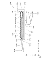

Classifications
-
- B—PERFORMING OPERATIONS; TRANSPORTING
- B65—CONVEYING; PACKING; STORING; HANDLING THIN OR FILAMENTARY MATERIAL
- B65G—TRANSPORT OR STORAGE DEVICES, e.g. CONVEYORS FOR LOADING OR TIPPING, SHOP CONVEYOR SYSTEMS OR PNEUMATIC TUBE CONVEYORS
- B65G61/00—Use of pick-up or transfer devices or of manipulators for stacking or de-stacking articles not otherwise provided for
-
- B—PERFORMING OPERATIONS; TRANSPORTING
- B25—HAND TOOLS; PORTABLE POWER-DRIVEN TOOLS; MANIPULATORS
- B25J—MANIPULATORS; CHAMBERS PROVIDED WITH MANIPULATION DEVICES
- B25J13/00—Controls for manipulators
- B25J13/08—Controls for manipulators by means of sensing devices, e.g. viewing or touching devices
- B25J13/081—Touching devices, e.g. pressure-sensitive
-
- B—PERFORMING OPERATIONS; TRANSPORTING
- B25—HAND TOOLS; PORTABLE POWER-DRIVEN TOOLS; MANIPULATORS
- B25J—MANIPULATORS; CHAMBERS PROVIDED WITH MANIPULATION DEVICES
- B25J15/00—Gripping heads and other end effectors
- B25J15/0014—Gripping heads and other end effectors having fork, comb or plate shaped means for engaging the lower surface on a object to be transported
-
- B—PERFORMING OPERATIONS; TRANSPORTING
- B25—HAND TOOLS; PORTABLE POWER-DRIVEN TOOLS; MANIPULATORS
- B25J—MANIPULATORS; CHAMBERS PROVIDED WITH MANIPULATION DEVICES
- B25J19/00—Accessories fitted to manipulators, e.g. for monitoring, for viewing; Safety devices combined with or specially adapted for use in connection with manipulators
- B25J19/02—Sensing devices
-
- B—PERFORMING OPERATIONS; TRANSPORTING
- B25—HAND TOOLS; PORTABLE POWER-DRIVEN TOOLS; MANIPULATORS
- B25J—MANIPULATORS; CHAMBERS PROVIDED WITH MANIPULATION DEVICES
- B25J9/00—Program-controlled manipulators
- B25J9/06—Program-controlled manipulators characterised by multi-articulated arms
-
- B—PERFORMING OPERATIONS; TRANSPORTING
- B65—CONVEYING; PACKING; STORING; HANDLING THIN OR FILAMENTARY MATERIAL
- B65G—TRANSPORT OR STORAGE DEVICES, e.g. CONVEYORS FOR LOADING OR TIPPING, SHOP CONVEYOR SYSTEMS OR PNEUMATIC TUBE CONVEYORS
- B65G23/00—Driving gear for endless conveyors; Belt- or chain-tensioning arrangements
- B65G23/22—Arrangements or mountings of driving motors
-
- B—PERFORMING OPERATIONS; TRANSPORTING
- B65—CONVEYING; PACKING; STORING; HANDLING THIN OR FILAMENTARY MATERIAL
- B65G—TRANSPORT OR STORAGE DEVICES, e.g. CONVEYORS FOR LOADING OR TIPPING, SHOP CONVEYOR SYSTEMS OR PNEUMATIC TUBE CONVEYORS
- B65G43/00—Control devices, e.g. for safety, warning or fault-correcting
- B65G43/08—Control devices operated by article or material being fed, conveyed or discharged
-
- B—PERFORMING OPERATIONS; TRANSPORTING
- B65—CONVEYING; PACKING; STORING; HANDLING THIN OR FILAMENTARY MATERIAL
- B65G—TRANSPORT OR STORAGE DEVICES, e.g. CONVEYORS FOR LOADING OR TIPPING, SHOP CONVEYOR SYSTEMS OR PNEUMATIC TUBE CONVEYORS
- B65G57/00—Stacking of articles
- B65G57/02—Stacking of articles by adding to the top of the stack
- B65G57/11—Stacking of articles by adding to the top of the stack the articles being stacked by direct action of the feeding conveyor
- B65G57/112—Stacking of articles by adding to the top of the stack the articles being stacked by direct action of the feeding conveyor the conveyor being adjustable in height
-
- B—PERFORMING OPERATIONS; TRANSPORTING
- B65—CONVEYING; PACKING; STORING; HANDLING THIN OR FILAMENTARY MATERIAL
- B65G—TRANSPORT OR STORAGE DEVICES, e.g. CONVEYORS FOR LOADING OR TIPPING, SHOP CONVEYOR SYSTEMS OR PNEUMATIC TUBE CONVEYORS
- B65G59/00—De-stacking of articles
- B65G59/02—De-stacking from the top of the stack
-
- B—PERFORMING OPERATIONS; TRANSPORTING
- B65—CONVEYING; PACKING; STORING; HANDLING THIN OR FILAMENTARY MATERIAL
- B65G—TRANSPORT OR STORAGE DEVICES, e.g. CONVEYORS FOR LOADING OR TIPPING, SHOP CONVEYOR SYSTEMS OR PNEUMATIC TUBE CONVEYORS
- B65G2201/00—Indexing codes relating to handling devices, e.g. conveyors, characterised by the type of product or load being conveyed or handled
- B65G2201/02—Articles
-
- B—PERFORMING OPERATIONS; TRANSPORTING
- B65—CONVEYING; PACKING; STORING; HANDLING THIN OR FILAMENTARY MATERIAL
- B65G—TRANSPORT OR STORAGE DEVICES, e.g. CONVEYORS FOR LOADING OR TIPPING, SHOP CONVEYOR SYSTEMS OR PNEUMATIC TUBE CONVEYORS
- B65G2814/00—Indexing codes relating to loading or unloading articles or bulk materials
- B65G2814/03—Loading or unloading means
- B65G2814/0301—General arrangements
- B65G2814/0304—Stacking devices
- B65G2814/0305—Adding to the top
-
- B—PERFORMING OPERATIONS; TRANSPORTING
- B65—CONVEYING; PACKING; STORING; HANDLING THIN OR FILAMENTARY MATERIAL
- B65G—TRANSPORT OR STORAGE DEVICES, e.g. CONVEYORS FOR LOADING OR TIPPING, SHOP CONVEYOR SYSTEMS OR PNEUMATIC TUBE CONVEYORS
- B65G2814/00—Indexing codes relating to loading or unloading articles or bulk materials
- B65G2814/03—Loading or unloading means
- B65G2814/0301—General arrangements
- B65G2814/0308—Destacking devices
- B65G2814/031—Removing from the top
Definitions
- This disclosure relates to robot hands, robots and robot systems.
- Patent Document 1 discloses an industrial robot having a belt conveyor at the tip of a hand.
- the robot of Patent Document 1 transfers a work transferred by a conveyor such as a production line to a belt conveyor at the tip of a hand. After the transfer is completed, the robot moves the belt conveyor to the transfer location, and transfers the work by moving the belt conveyor backward while sending out the work by the belt conveyor.
- the robot of Patent Document 1 can put a work conveyed by a conveyor or the like on a belt conveyor, but cannot put a stationary work placed on a floor surface or the like on a belt conveyor.
- the robot hand is a robot hand that moves an article, and includes a conveyor having an endless belt for conveying the article and the conveyor in the conveying direction of the conveyor.
- the insertion portion includes an insertion portion arranged at the end of the conveyor, and the insertion portion has a shape capable of being inserted into a gap between articles arranged adjacent to each other.
- the robot according to one aspect of the present disclosure includes a robot hand according to one aspect of the present disclosure, a robot arm connected to the robot hand, and a control device for controlling the operation of the robot hand and the robot arm.
- the robot system includes a robot according to one aspect of the present disclosure and an operating device for operating the robot.
- FIG. 1 is a diagram showing an example of a configuration of a robot system according to an embodiment.
- FIG. 2 is a side view showing an example of the configuration of the robot according to the embodiment.
- FIG. 3 is a side view showing an example of the configuration of the robot hand according to the embodiment.
- FIG. 4 is a block diagram showing an example of the functional configuration of the control device according to the embodiment.
- FIG. 5 is a block diagram showing an example of the configuration of the control device and each drive device according to the embodiment.
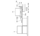
- FIG. 6 is a side view showing one of the loading operations of the robot system according to the embodiment.
- FIG. 7 is a side view showing one of the loading operations of the robot system according to the embodiment.
- FIG. 8 is a side view showing one of the loading operations of the robot system according to the embodiment.
- FIG. 1 is a diagram showing an example of a configuration of a robot system according to an embodiment.
- FIG. 2 is a side view showing an example of the configuration of the robot according to the embodiment.
- FIG. 9 is a side view showing one of the loading operations of the robot system according to the embodiment.
- FIG. 10 is a side view showing one of the unloading operations of the robot system according to the embodiment.
- FIG. 11 is a side view showing one of the unloading operations of the robot system according to the embodiment.
- FIG. 12 is a side view showing one of the unloading operations of the robot system according to the embodiment.
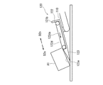
- FIG. 13 is a side view showing an example of the configuration of a modified example of the robot hand according to the embodiment.
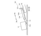
- FIG. 14 is a side view showing an example of the configuration of another modification of the robot hand according to the embodiment.
- FIG. 1 is a diagram showing an example of the configuration of the robot system 1 according to the embodiment.
- the robot system 1 is a system that uses the robot 100 to convey the article A.
- the robot 100 can place and stack the articles A transported by the transport device or the like in a predetermined place. Further, the robot 100 takes out the article A from the pile of the articles A piled up at a predetermined place and places it on another device or the like.
- the article A transported by the robot 100 will be described as a rectangular parallelepiped corrugated cardboard case, but the present invention is not limited to this.
- the article to be transported may be any object that can be placed on the conveyor 122 described later, for example, another object having a predetermined shape, or an object that does not have a predetermined shape such as rock. You may.
- the robot system 1 includes a robot 100 and an operating device 210 for operating the robot 100.
- the operation device 210 is arranged away from the robot 100, and the operator P can remotely control the robot 100 by inputting to the operation device 210.
- the robot system 1 includes an imaging device 220 that captures the operating state of the robot 100, and an output device 230 that outputs information captured by the imaging device 220.
- the robot system 1 includes a transport vehicle 240 to which the robot arm 110 of the robot 100 is fixed.
- the transport vehicle 240 has a servomotor that uses electric power as a power source to drive the transport vehicle 240.
- the automatic guided vehicle 240 may be an AGV (automated guided vehicle). It should be noted that not all of the above components of the robot system 1 are indispensable.
- the robot 100 includes a robot arm 110, a robot hand 120 attached to the tip of the robot arm 110, and a control device 130 for controlling the operation of the robot arm 110 and the robot hand 120.
- the robot 100 is configured as a vertical articulated robot, but is not limited thereto.
- the operating device 210 remotely controls the robot 100 and the transport vehicle 240 based on a command input by the operator P.
- the specific configuration of the operating device 210 is not particularly limited, but the operating device 210 includes an input device that receives an input by the operator P. Examples of input devices include, but are not limited to, handles, levers, pedals, buttons, touch panels, microphones, cameras, and the like.
- the operation device 210 outputs a command corresponding to the operation input via the input device to the control device 130.
- the operating device 210 is connected to the control device 130 via wired communication or wireless communication.
- the format of wired communication and wireless communication may be any format.
- the operation device 210 may output a command corresponding to each operation of the manual operation input by the operator P to the control device 130.
- the operation device 210 may output a command corresponding to the operation content of the automatic operation input by the operator P to the control device 130.
- the operating device 210 may accept displacement, direction, speed, operating force, etc. of the handle or lever as an input command, may accept pressing and pressing of a button, and may touch or touch the screen of the touch panel.
- the locus, the contact pressure, and the like may be accepted, the audio signal collected by the speaker may be accepted, and the analysis result of the image of the operator P captured by the camera may be accepted.
- the operating force is a force applied to the handle, lever, or the like by the operator P.
- the contact pressure is the pressing force of a finger or the like on the touch panel.
- the analysis result of the image of the operator P includes a command indicated by the gesture of the operator P and the like.
- the image pickup device 220 captures the operating state of the robot 100, the transport vehicle 240, and the like, and outputs the signal of the captured image to the output device 230.
- the image captured by the image pickup device 220 may be a still image or a moving image. Examples of the image pickup device 220 are a digital camera and a digital video camera.
- the image pickup device 220 is connected to the operation device 210 and the output device 230 via wired communication or wireless communication.
- the imaging device 220 may perform operations such as executing and stopping imaging and changing the imaging direction in accordance with a command input to the operating device 210.
- the output device 230 is a display device that outputs an image signal acquired from the image pickup device 220 as an image and displays it on the operator P.
- Examples of the output device 230 are, but are not limited to, a liquid crystal display and an organic or inorganic EL display (Electro-Luminescence Display).
- the output device 230 may display an image for an operation or the like output by the control device 130.
- FIG. 2 is a side view showing an example of the configuration of the robot 100 according to the embodiment.
- the robot arm 110 of the robot 100 is fixed to the transport vehicle 240 at its base end.
- a robot hand 120 is connected to the tip of the robot arm 110.
- the articulated robot arm 110 has six joint axes JT1 to JT6 and six links 110a to 110f sequentially connected by these joint axes.
- the robot arm 110 has arm drive devices AM1 to AM6 for rotationally driving each of the joint axes JT1 to JT6.
- the operation of the arm drive devices AM1 to AM6 is controlled by the control device 130.
- each of the arm drive devices AM1 to AM6 uses electric power as a power source and has a servomotor as an electric motor for driving them.
- the number of joint axes of the robot arm 110 is not limited to 6, but may be 7 or more, or 1 or more and 5 or less.
- the joint shaft JT1 rotatably connects the upper surface of the base 241 of the transport vehicle 240 and the base end portion of the link 110a around an axis in the vertical direction perpendicular to the upper surface.
- the joint axis JT2 rotatably connects the tip end of the link 110a and the base end of the link 110b around an axis in the horizontal direction.
- the joint axis JT3 rotatably connects the tip end of the link 110b and the base end of the link 110c around an axis in the horizontal direction.
- the joint axis JT4 rotatably connects the tip end of the link 110c and the base end of the link 110d around the longitudinal axis of the link 110c.
- the joint axis JT5 rotatably connects the tip end of the link 110d and the base end of the link 110e around an axis in a direction orthogonal to the longitudinal direction of the link 110d.
- the joint axis JT6 connects the tip end portion of the link 110e and the base end portion of the link 110f so as to be twistably rotatable with respect to the link 110e.
- the robot hand 120 is attached to the tip of the link 110f.
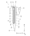
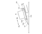
- FIG. 3 is a side view showing an example of the configuration of the robot hand 120 according to the embodiment.
- the robot hand 120 includes a base 121, a conveyor 122, an insertion portion 123, and a sensor 124.
- the base 121 is attached to the tip of the link 110f of the robot arm 110.
- the conveyor 122 and the insertion portion 123 are attached to the base 121 and supported by the base 121.
- the base 121 includes a plate-shaped support portion 121a that supports the conveyor 122 mounted on the upper surface 121aa, and a stopper 121b at the end portion 121ab of the support portion 121a.
- the stopper 121b has a plate-like shape protruding from the upper surface 121aa in the upward direction D1a.
- the direction D1a is a direction perpendicular to the upper surface 121aa
- the direction D1b is a direction opposite to the direction D1a.
- the stopper 121b projects in the direction D1a from the conveyor 122 mounted on the upper surface 121aa.
- the conveyor 122 is configured as a belt conveyor.
- the conveyor 122 can convey the article A placed on it in the directions D2a and D2b which are opposite to each other.
- the directions D2a and D2b are the transport directions of the conveyor 122.
- the direction D2a is the transport direction when the article A placed on the conveyor 122 is unloaded
- the direction D2b is the transport direction when the article A is loaded on the conveyor 122.
- the conveyor 122 is arranged and fixed on the upper surface 121aa of the support portion 121a so that the end portion 122f of the direction D2b of the conveyor 122 is adjacent to the stopper 121b.
- the conveyor 122 includes a roller 122a, a plurality of rollers 122b, a support frame 122c, a conveyor belt 122d, and a conveyor driving device 122e.
- the plurality of rollers 122a and 122b are arranged in the direction D2a or D2b, the roller 122a is the main roller, and the roller 122b is the driven roller.
- the support frame 122c extends in the direction D2a or D2b and supports the roller 122a and the plurality of rollers 122b.
- the transport belt 122d is a ring-shaped endless belt and is hung around the rollers 122a and 122b.
- the conveyor drive device 122e rotationally drives the rollers 122a.
- the conveyor drive device 122e uses electric power as a power source and has a servomotor as an electric motor for driving the electric power.
- the servo motor is an example of a conveyor drive motor.
- the conveyor drive device 122e and the roller 122a are arranged at the end portion 122f of the conveyor 122.
- the operation of the conveyor drive device 122e is controlled by the control device 130.
- the conveyor drive device 122e may be supplied with electric power from the robot 100, the electric power supply source of the robot 100, or other electric power supply sources.
- the roller 122a When the conveyor drive device 122e rotationally drives the roller 122a in one direction, the roller 122a makes the transport belt 122d orbit around the rollers 122a and 122b in one direction, whereby the transport surface 122da of the conveyor belt 122d is moved in the direction D2b. That is, it moves toward the stopper 121b.
- the transport surface 122da is an outer peripheral surface of a portion of the transport belt 122d located in the direction D1a with respect to the rollers 122a and 122b. Therefore, the conveyor 122 conveys the article A placed on the conveying surface 122da in the direction D2b.
- the conveyor drive device 122e rotationally drives the roller 122a in the opposite direction
- the roller 122a orbits the conveyor belt 122d in the opposite direction, whereby the conveyor surface 122da moves away from the direction D2a, that is, the stopper 121b. Therefore, the conveyor 122 conveys the article A placed on the conveying surface 122da in the direction D2a.
- the insertion portion 123 is arranged at the end portion 121ac of the support portion 121a on the opposite side of the end portion 121ab.
- the conveyor 122 is located between the insertion portion 123 and the stopper 121b, and the insertion portion 123 is adjacent to the end portion 122g of the direction D2a of the conveyor 122.
- the stopper 121b, the conveyor 122, and the insertion portion 123 are arranged in this order in the direction D2a. That is, the insertion portion 123 is arranged at the end portion 122g of the conveyor 122 in the transport direction D2a of the conveyor 122.
- the insertion portion 123 may be integrally formed of the same material as the support portion 121a, or the insertion portion 123 of another part may be attached to the support portion 121a.
- the insertion portion 123 extends in the direction D2a from the end portion 121ac of the support portion 121a.
- the insertion portion 123 has a shape that can be inserted into a gap between adjacent articles and / or a gap between the article and the floor surface.
- the insertion portion 123 has an inclined upper surface 123a facing the direction D1a, and the inclined upper surface 123a extends in a direction diagonally intersecting the transport surface 122da of the conveyor 122.
- the inclined upper surface 123a is inclined toward the direction D1b toward the direction D2a.
- the insertion portion 123 has a tapered shape that tapers toward the tip of the direction D2a. Specifically, the thickness of the insertion portion 123 in the direction D1a or D1b decreases toward the direction D2a. Further, the width of the insertion portion 123 in the direction D3a or D3b (see FIG. 1) is substantially constant, but may become smaller toward the direction D2a.
- the directions D3a and D3b are opposite to each other and are along the upper surface 121aa which is perpendicular to the directions D1a, D1b, D2a and D2b. In the present embodiment, the directions D1a and D1b and the directions D2a and D2b are substantially vertical, but the present invention is not limited to this, and the directions D1a and D1b may intersect diagonally.
- the insertion portion 123 is configured to have a height that does not protrude from the transport surface 122da in the direction D1a with reference to the support portion 121a. That is, the inclined upper surface 123a is configured so as not to protrude from the transport surface 122da in the direction D1a. Further, the height of the insertion portion 123 in the direction D1a may be 1 ⁇ 2 or more of the height in the direction D1a of the conveyor 122. For example, the position of the highest portion of the inclined upper surface 123a may be equal to or higher than the position of the axial center of the roller 122a or 122b adjacent to the insertion portion 123.
- the width of the inclined upper surface 123a in the direction D3a or D3b may be any width as long as it can carry the article A to be transported, and may be larger or smaller than the width of the transport surface 122da, and is the same. May be good.
- the shape of the insertion portion 123 as described above is a wedge-like triangular columnar shape, but the shape is not limited to this.
- the inclined upper surface 123a is a flat surface in the present embodiment, but may be curved or bent.
- the inclined upper surface 123a may be curved or bent so as to draw a convex or concave arc or a polygonal line toward the direction D2b.
- the sensor 124 is a sensor that detects the approach of an object such as an article A to the sensor 124, and outputs a detection signal indicating the approach to the control device 130.
- the sensor 124 may be a contact type sensor or a non-contact type sensor.
- the contact type sensor may be a sensor that detects the approach of an object by detecting contact with an object such as a bumper sensor, a pressure sensitive sensor, and a contact type displacement sensor.
- Non-contact sensors detect the approach of an object such as a photoelectric sensor (also called a "beam sensor"), a laser sensor, a laser lidar, and an ultrasonic sensor by detecting the approach of the object or the distance to the object. It may be a sensor that does.
- the sensor 124 is a non-contact type sensor, is arranged on the stopper 121b, and has the transport surface 122da of the transport belt 122d as the detection target region.
- the robot hand 120 as described above can load the article A on the transport surface 122 da of the conveyor 122, and can unload the article A on the transport surface 122 da.
- the conveyor 122 drives the transport surface 122da so as to move in the direction D2b.
- the frictional force between the conveyor belt 122d and the article A the article A can be pulled in the direction D2b and the entire article A can be placed on the conveyor surface 122da.
- the conveyor 122 continues to be driven after the entire article A is placed on the conveying surface 122da, the article A is stopped from moving in the direction D2b by abutting on the stopper 121b, and is prevented from moving on the conveying surface 122da. The fall of the article A from is suppressed.
- the conveyor 122 drives the transport surface 122da to move in the direction D2a to move the article A in the direction D2a, and further, the conveyor 122 and the conveyor belt 122d
- the entire article A can be lowered onto the inclined upper surface 123a of the insertion portion 123.
- Control device 130 The configuration of the control device 130 will be described.
- the control device 130 controls the operations of the robot arm 110, the robot hand 120, and the transport vehicle 240 according to a program stored in a storage unit (not shown) in advance based on an operation command or the like received from the operation device 210.
- the control device 130 does not control the operations of the robot arm 110, the robot hand 120, and the transport vehicle 240 individually, but links them to each other to control the operations, and realizes the operations linked to each other.
- the control device 130 reflects information acquired from the other two in one control of the robot arm 110, the robot hand 120, and the transport vehicle 240.
- FIG. 4 is a block diagram showing an example of the functional configuration of the control device 130 according to the embodiment.
- the control device 130 includes an operation information processing unit 130a, a conveyor control unit 130b, a hand position detection unit 130c, an arm control unit 130d, an arm position detection unit 130e, a conveyor vehicle control unit 130f, and a conveyor vehicle position detection unit.
- the 130g, the information output unit 130h, and the storage unit 130i are included as functional components. These functional components use the information output by the other components and perform operations linked to the operations of the other components. It should be noted that not all of the above functional components are essential.
- the function is realized by a computer system (not shown) consisting of a processor such as a CPU (Central Processing Unit), a volatile memory such as a RAM (Random Access Memory), and a non-volatile memory such as a ROM (Read-Only Memory). You may. Some or all of the functions of the above components may be realized by the CPU using the RAM as a work area to execute a program recorded in the ROM.
- the functions of the above components may be realized by the above computer system, may be realized by a dedicated hardware circuit such as an electronic circuit or an integrated circuit, and may be realized by a computer system and a hardware circuit. It may be realized by a combination.
- the storage unit 130i can store various kinds of information and can read the stored information.
- the storage unit 130i is realized by a semiconductor memory such as a volatile memory and a non-volatile memory, a hard disk, and a storage device such as an SSD (Solid State Drive).
- the storage unit 130i stores parameters, threshold values, and the like used by each component.
- the storage unit 130i may store a program executed by each component.
- the operation information processing unit 130a outputs an operation command acquired from the operation device 210 to each component of the control device 130. Each component operates according to the program corresponding to the directive.
- the conveyor control unit 130b controls the operation of the conveyor drive device 122e according to a command acquired via the operation information processing unit 130a. Specifically, the conveyor control unit 130b controls the rotational drive operation of the roller 122a by the conveyor drive device 122e for moving the conveyor surface 122da of the conveyor belt 122d in the direction D2a or D2b. Further, when the conveyor control unit 130b receives a detection signal indicating the approach of an object to the sensor 124 from the sensor 124, the conveyor control unit 130b stops the conveyor drive device 122e.
- the hand position detection unit 130c and the control device 130 are examples of detection devices.
- the hand position detection unit 130c detects the position of the insertion unit 123 with respect to the article A. Specifically, the hand position detection unit 130c detects the output load generated in each of the arm drive devices AM1 to AM6 by acquiring the output current signal from each of the arm drive devices AM1 to AM6 of the robot arm 110. To do. Further, the hand position detection unit 130c acquires information on the input load generated in each of the arm drive devices AM1 to AM6 from the arm control unit 130d. The hand position detection unit 130c detects whether or not the tapered tip of the insertion unit 123 is in contact with the article A based on the difference between the output load and the input load of the arm drive devices AM1 to AM6. For example, the hand position detection unit 130c may detect that the tip of the insertion unit 123 is in contact with the article A when the difference in load between the arm drive devices AM1 to AM6 is equal to or greater than the threshold value.
- the output current, input load, and output load of the arm drive devices AM1 to AM6 are examples of information regarding the operation of the arm drive devices AM1 to AM6.
- the information regarding the operation of the arm drive devices AM1 to AM6 may include the strain amount of the joint axes JT1 to JT6 and the links 110a to 110f. It is also possible to detect the presence or absence of contact between the tip of the insertion portion 123 and the article A by using such a strain amount.
- the hand position detecting unit 130c acquires information such as the position, posture, moving direction, and moving speed of the link 110f of the robot arm 110 from the arm position detecting unit 130e, and uses the information to obtain the position of the robot hand 120. Acquire information such as posture, moving direction, and moving speed.
- the hand position detection unit 130c uses the above information to detect the position of the insertion unit 123. For example, the hand position detecting unit 130c is inserted while the insertion unit 123 is detecting that the insertion unit 123 is in contact with the article A and is moving in a direction intersecting the projecting direction, specifically orthogonal to the article A.
- the insertion part 123 is located at a position corresponding to the gap between the articles A arranged adjacent to each other.
- the position corresponding to the gap may be a position above the gap in the vertical direction or a position on the side in the horizontal direction of the gap.
- the arm control unit 130d controls the operations of the arm drive devices AM1 to AM6 in accordance with a command acquired via the operation information processing unit 130a to cause the robot arm 110 to perform an operation corresponding to the robot arm 110.
- the arm control unit 130d causes the robot arm 110 to operate based on the positions, postures, movement directions, movement speeds, and the like of the links 110a to 110f of the robot arm 110 acquired from the arm position detection unit 130e.
- the arm position detection unit 130e detects the position and posture of each of the links 110a to 110f of the robot arm 110. Specifically, the arm position detection unit 130e acquires information on the amount of motion such as the amount of rotation from the arm drive devices AM1 to AM6, and detects the position and posture of each of the links 110a to 110f based on the amount of motion. Further, the arm position detection unit 130e detects the movement direction and the movement speed of the links 110a to 110f from the changes in the positions and postures of the links 110a to 110f.
- the transport vehicle control unit 130f controls the operation of the transport drive device 240a of the transport vehicle 240 according to a command acquired via the operation information processing unit 130a, thereby causing the transport vehicle 240 to perform an operation corresponding to the transport vehicle 240.
- the transport vehicle control unit 130f is operated by the transport vehicle 240 based on the position and orientation of the transport vehicle 240 acquired from the transport vehicle position detection unit 130g.
- the transport vehicle position detection unit 130 g detects the position and orientation of the transport vehicle 240. Specifically, the transport vehicle position detection unit 130g acquires information on the operating amount such as the rotation amount of the servomotor from the transport driving device 240a, and detects the position and orientation of the transport vehicle 240 based on the operating amount. ..
- the transport vehicle 240 may be provided with a GPS (Global Positioning System) receiver and a position measuring device such as an IMU (Inertial Measurement Unit).
- the transport vehicle position detection unit 130g may detect the position and orientation of the transport vehicle 240 by using the reception signal of the GPS receiver, the acceleration and the angular velocity measured by the IMU, and the like.
- the transport vehicle position detection unit 130g may detect, for example, a weak induced current from an electric wire embedded in the floor surface, and detect the position and orientation of the transport vehicle 240 based on this detected value.
- the information output unit 130h outputs output information such as an operation result and a detection result of each component of the control device 130 to the operation device 210 and / or the output device 230. Further, the information output unit 130h outputs a screen for operating the robot 100 to the operation device 210 and / or the output device 230.
- FIG. 5 is a block diagram showing an example of the configuration of the control device 130 and each drive device according to the embodiment.
- the control device 130 inputs / outputs information and commands to the servomotors of the arm drive devices AM1 to AM6, the servomotors of the conveyor drive devices 122e, and the servomotors of the conveyor drive device 240a. It is configured in.
- the control device 130 controls the operations of all the servomotors of the arm drive devices AM1 to AM6, the conveyor drive device 122e, and the transfer drive device 240a.
- Each servomotor is equipped with an electric motor and an encoder that detects the rotation angle of the rotor of the electric motor.
- Each servomotor operates an electric motor according to a command and information output from the control device 130, and outputs a detection value of the encoder to the control device 130.
- the control device 130 detects the rotation amount and rotation speed of the rotor of the servomotor based on the detection value of the encoder fed back from each servomotor, and uses the detection result to start and stop the rotation of the servomotor. , Rotation speed and rotation torque are controlled.
- the control device 130 can stop each servomotor at an arbitrary rotation position, rotate it at an arbitrary rotation speed, and operate it at an arbitrary rotation torque. Therefore, the control device 130 can operate all of the robot arm 110, the conveyor 122, and the transport vehicle 240 in various and precise manners.
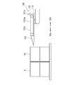
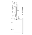
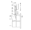
- FIG. 6 to 9 are side views showing one of the loading operations of the robot system 1 according to the embodiment, respectively.
- the operator P moves the transport vehicle 240 to the mountain of the article A including the article A1 to be carried out by inputting a command to the operating device 210.
- the operator P may input the information on the position of the destination into the operation device 210, and the control device 130 may automatically drive the transport vehicle 240 according to the information.
- the operator P may operate the operation device 210 while visually recognizing it through the screen or the like displayed on the output device 230 to drive the transport vehicle 240.
- the operator P operates the operation device 210 while visually recognizing it through the screen of the output device 230 or the like.
- the robot arm 110 is operated to move the robot hand 120 to the side of the article A1.
- the control device 130 outputs information on the posture of the robot hand 120 to the operation device 210 and the like, and the operator P uses the information on the posture so that the tip of the insertion portion 123 faces the side surface of the article A1 and the conveyor 122 is conveyed.
- the posture of the robot hand 120 is adjusted so that the surface 122da is horizontal.
- the operator P moves the robot hand 120 in the horizontal direction and brings the tip of the direction D2a of the insertion portion 123 into contact with the side surface of the article A1 from the side. Further, the operator P lowers the robot hand 120 with the insertion portion 123 in contact with the robot hand 120.
- the control device 130 outputs information indicating the presence or absence of contact between the insertion unit 123 and the article A1 to the operation device 210 or the like.
- the operator P stops the lowering of the robot hand 120 when the insertion portion 123 and the article A1 are in a non-contact state. At this time, the tip of the insertion portion 123 faces the gap between the article A1 and the article A below it in the horizontal direction.
- the control device 130 detects the non-contact state, the lowering of the robot hand 120 may be automatically stopped.
- the operator P moves the robot hand 120 in the horizontal direction D2a.
- the insertion portion 123 is inserted into the gap between the article A1 and the article A below it.
- the operator P activates the conveyor drive device 122e in parallel with the start of movement of the robot hand 120 in the direction D2a, and orbits the conveyor belt 122d of the conveyor 122 so as to move the conveyor surface 122da in the direction D2b.
- the article A1 is first placed on the inclined upper surface 123a of the insertion portion 123, lifted diagonally, and moved on the inclined upper surface 123a in the direction D2b.
- the article A1 comes into contact with the transfer belt 122d at the end 122g of the conveyor 122, the article A1 is pulled in the direction D2b by the orbiting transfer belt 122d, and the entire article A1 is placed on the transfer surface 122da.
- the article A1 on the transport surface 122da is transported in the direction D2b by the transport belt 122d.
- the control device 130 stops the conveyor drive device 122e.
- the coefficient of friction between the transport belt 122d and the article A1 is larger than the coefficient of friction between the inclined upper surface 123a of the insertion portion 123 and the article A1 so that the transport belt 122d can stably pull in the article A1. Larger is preferred.
- the movement of the robot hand 120 in the direction D2a may be stopped at any timing after the contact between the article A1 and the transport belt 122d.
- the timing of stopping the movement of the robot hand 120 may be the timing at which the conveyor drive device 122e is stopped, and the tip of the insertion portion 123 comes into contact with the article A adjacent to the article A1 in the direction D2a in the depth direction. It may be timing.
- the movement stop of the robot hand 120 may be performed by the operator P via the operation device 210, or may be automatically performed by the control device 130.
- control device 130 may detect the contact between the article A1 and the transport belt 122d based on the difference between the output load and the input load of the conveyor drive device 122e, similarly to the arm drive devices AM1 to AM6. Further, the control device 130 may detect the contact between the insertion unit 123 and the article A based on the difference between the output load and the input load of the arm drive devices AM1 to AM6. The control device 130 may output the detection result to the operation device 210 or the like, or may stop the movement of the robot hand 120 based on the detection result.
- the operator P operates the robot arm 110 to move the article A1 mounted on the robot hand 120 to the article. Carry out from mountain A and move to the destination.
- At least one of the operations of each step, or at least a part of a series of operations from the moving step to the carrying-out step may be automatically performed by the control device 130.
- 10 to 12 are side views showing one of the unloading operations of the robot system 1 according to the embodiment, respectively.
- the operator P moves the robot hand 120 by operating the operation device 210, and the insertion unit 123.
- the tip of the robot is brought into contact with the floor surface or located near the floor surface.
- the control device 130 outputs information indicating the presence / absence of contact between the insertion unit 123 and the floor surface to the operation device 210 or the like, and the operator P adjusts the position and posture of the robot hand 120 based on the information on the presence / absence of contact. ..
- the operator P stops the movement of the robot hand 120 and starts the conveyor drive device 122e.
- the conveyor drive device 122e orbits the conveyor belt 122d so as to move the conveyor surface 122da in the direction D2a.
- the article A1 moves in the direction D2a together with the transport surface 122da and rests on the inclined upper surface 123a of the insertion portion 123. Further, the article A1 is moved by the transport belt 122d and comes into contact with the floor surface.
- the operator P or the control device 130 may incline the robot hand 120 so that the transport surface 122da is inclined in order to facilitate the movement of the article A1 from the inclined upper surface 123a to the floor surface.
- the control device 130 may detect the contact of the article A1 with the floor surface based on the load of the conveyor drive device 122e and output the detection result to the operation device 210 or the like.
- the operator P moves the robot hand 120 in the horizontal direction toward the direction D2a or D2b to move the position of the article A1. Adjust.
- the operator P moves the robot hand 120 in the horizontal direction toward the direction D2b to move the insertion portion 123 between the article A1 and the floor surface. Pull out from between.
- the article A1 is placed on the floor surface.
- the control device 130 may detect the presence or absence of the article A1 on the conveyor belt 122d based on the load of the conveyor drive device 122e, and output the detection result to the operation device 210 or the like.
- At least one of the operations of each step, or at least a part of a series of operations from the moving step to the mounting step may be automatically performed by the control device 130.
- the robot hand 120 is an insertion arranged at a conveyor 122 having an endless conveyor belt 122d for conveying an article and an end portion 122g of the conveyor 122 in the conveyor 122 transport direction D2a.
- a portion 123 is provided, and the insertion portion 123 has a shape that can be inserted into a gap between articles arranged adjacent to each other.
- the robot hand 120 inserts the insertion portion 123 into the gap between the articles to place the article on the insertion portion 123 and lifts the article, and puts the lifted article onto the conveyor belt 122d of the conveyor 122. Can be contacted. Further, by driving the conveyor 122, the robot hand 120 can pull the article onto the transfer belt 122d by the action of the frictional force between the article and the transfer belt 122d, and place the article on the transfer belt 122d. Therefore, the robot hand 120 makes it possible to place a stationary article on the conveyor 122 and transfer it.
- the insertion portion 123 may have an inclined upper surface 123a extending in a direction diagonally intersecting the transport surface 122da of the transport belt 122d.
- the insertion portion 123 may have a tapered shape in which the thickness of the direction D1a or D1b, which is the direction perpendicular to the transport surface 122da, becomes smaller.
- the robot hand 120 inserts the insertion portion 123 into the gap between the articles, so that the article is placed on the inclined upper surface 123a and lifted obliquely. As a result, the robot hand 120 can place at least a part of the article on the transport belt 122d.
- the insertion portion 123 does not have to protrude from the transport surface 122da in the direction D1a which is the direction perpendicular to the transport surface 122da of the transport belt 122d. According to the above configuration, when the insertion portion 123 is inserted into the gap between the articles, the article placed on the insertion portion 123 is likely to come into contact with the transport belt 122d. This makes it easier for the conveyor 122 to pull the article onto the transport belt 122d.
- the conveyor 122 may include a conveyor drive device 122e having a conveyor drive motor for driving the conveyor belt 122d.
- the robot hand 120 drives the conveyor 122 using electric power as a power source. Therefore, the robot hand 120 does not require the piping required when the drive source is air pressure, liquid pressure, or the like. Further, the robot hand 120 can receive power supply from the power supply source of the robot 100. Therefore, the degree of freedom of installation and movement of the robot hand 120 is improved.
- control device 130 may be provided as a detection device for detecting that the insertion portion 123 is at a position corresponding to a gap between articles arranged adjacent to each other. According to the above configuration, the insertion portion 123 can be reliably inserted into the gap between the articles.
- the robot hand 120 is connected to a robot arm 110 having a plurality of joints driven by arm drive devices AM1 to AM6 having a servomotor, and the control device 130 is the arm drive devices AM1 to AM6.
- Information on the operation may be acquired, and the information on the operation of the arm drive devices AM1 to AM6 may be used to detect that the insertion portion 123 is at a position corresponding to a gap between articles arranged adjacent to each other.
- a dedicated device for detecting that the insertion portion 123 is at a position corresponding to the gap between the articles is not required. Therefore, the configuration of the robot hand 120 can be simplified.
- the robot 100 includes a robot hand 120, a robot arm 110 connected to the robot hand 120, and a control device 130 for controlling the operation of the robot hand 120 and the robot arm 110. According to the above configuration, the same effect as that of the robot hand 120 according to the embodiment can be obtained.
- the robot arm 110 has a plurality of joints driven by arm drive devices AM1 to AM6 having a servomotor
- the conveyor 122 is a conveyor drive motor that drives the conveyor belt 122d. May have a servomotor.
- the control device 130 may control the operation of the servomotor of the conveyor 122 and the operation of the servomotors of the arm drive devices AM1 to AM6.
- the servomotor can stop the rotor at an arbitrary rotation position, can rotate the rotor at an arbitrary rotation speed, and can generate an arbitrary rotation torque. Therefore, the conveyor 122 and the robot arm 110 can perform various and precise operations.
- the robot system 1 includes a robot 100 and an operating device 210 for operating the robot 100. According to the above configuration, the same effect as that of the robot hand 120 according to the embodiment can be obtained.
- the shape of the insertion portion 123 of the robot hand 120 is a shape that tapers toward the tip thereof, but the shape is not limited to this.
- the shape of the insertion portion 123 may be any shape that can be inserted into the gap between adjacent articles and / or the gap between the article and the floor surface.
- the shape of the insertion portion 123 may be a shape in which the thickness is substantially constant toward the tip thereof, or a shape in which the thickness is larger toward the tip thereof.
- the shape of the insertion portion 123 may be a shape having a larger width toward the tip thereof.
- the following insertion portion can be exemplified.
- FIG. 13 is a side view showing an example of the configuration of a modified example of the robot hand according to the embodiment.
- the insertion portion 123A of the robot hand 120A shown in FIG. 13 has an inclined upper surface 123Aa similar to the inclined upper surface 123a of the insertion portion 123 of the embodiment.
- the thickness of the insertion portion 123A in the direction D1a or D1b is substantially constant toward the direction D2a. That is, the insertion portion 123A has a plate-like shape inclined with respect to the transport surface 122da of the transport belt 122d.
- Such an insertion portion 123A can be inserted into a gap between adjacent articles and / or a gap between the article and the floor surface.
- the insertion portion 123A can be inserted into the gap.
- the insertion portion 123A is inclined in the direction D1b toward the direction D2a, but may be inclined in the direction D1a.
- FIG. 14 is a side view showing an example of the configuration of another modified example of the robot hand according to the embodiment.
- the insertion portion 123B of the robot hand 120B shown in FIG. 14 has a plate-like shape similar to the insertion portion 123A of FIG. However, the insertion portion 123B has an upper surface 123Ba substantially parallel to the transport surface 122da of the transport belt 122d. That is, the insertion portion 123B has a plate-like shape substantially parallel to the transport surface 122da.
- Such an insertion portion 123B can be inserted into a gap between adjacent articles and / or a gap between the article and the floor surface.
- the control device 130 detects the position and contact of the insertion portion 123 with respect to the article based on the change in the load of the arm drive devices AM1 to AM6 of the robot arm 110, but the present invention is not limited to this.
- a force sensor for detecting the magnitude and direction of the force may be provided on the links 110a to 110f such as the link 110f of the robot arm 110. Then, the control device 130 may detect the position and contact of the insertion portion 123 based on the detection signal of the force sensor.
- a non-contact sensor such as a photoelectric sensor, a laser sensor, a laser rider, or an ultrasonic sensor may be provided at or near the insertion portion 123.
- the control device 130 may detect the position and contact of the insertion unit 123 based on the detection signal of the non-contact sensor.
- an imaging device that images the tip of the insertion unit 123 may be provided at or near the insertion unit 123.
- imaging devices are digital cameras and digital video cameras.
- the imaging device may be arranged so as to be able to capture an image including the tip of the insertion portion 123 and an article approaching the tip.
- the control device 130 may detect the article by analyzing the image captured by the image pickup device, and may detect the positional relationship such as the distance between the insertion unit 123 and the article.
- control device 130 detects the presence or absence of contact with the conveyor belt 122d based on the change in the load of the conveyor drive device 122e, but the present invention is not limited to this.
- the control device 130 uses the loads of the arm drive devices AM1 to AM6 of the robot arm 110, the detection signal of the force sensor provided on the robot arm 110, and the like in combination with the load of the conveyor drive device 122e, or It may be used as an alternative.
- the robot 100 is a vertical articulated robot, but the robot 100 is not limited to this.
- the robot 100 may be configured as a polar coordinate robot, a cylindrical coordinate robot, a Cartesian coordinate robot, a horizontal articulated robot, or other robots.
- the robot 100 is mounted on the transport vehicle 240 and can be moved, but the present invention is not limited to this, and the robot 100 may be fixed to the floor surface or the like.
- the robot system 1 includes an image pickup device 220 and an output device 230, but the robot system 1 is not limited thereto.
- the robot system 1 may not include the image pickup device 220 and the output device 230, and may be configured so that the operator P can directly see the robot system 1.
- the robot system 1 is configured such that the operator P operates the robot 100 and the transport vehicle 240 in a master-slave manner using the operating device 210, but the present invention is not limited to this.
- the robot system 1 may be configured to operate the robot 100 and the transport vehicle 240 fully automatically.
- the robot 100 and the transport vehicle 240 may automatically operate only by the operator P inputting a command indicating the work content or the like to the operation device 210.
- the control device is based on the detection signal of the proximity sensor provided at the tip of the robot arm, the analysis value of the image of the camera provided at the tip of the robot arm, and the like. The movements of the robot arm and the robot hand may be controlled.
- Robot system 100 Robot 110 Robot arm 120, 120A, 120B Robot hand 122 Conveyor 122d Conveyor belt 122da Conveyor surface 122e Conveyor drive device (conveyor drive motor) 122g Ends 123, 123A, 123B Insert 130 Control device (detection device) 210 Operating device AM1 to AM6 Arm drive device
Landscapes
- Engineering & Computer Science (AREA)
- Mechanical Engineering (AREA)
- Robotics (AREA)
- Human Computer Interaction (AREA)
- Manipulator (AREA)
- Stacking Of Articles And Auxiliary Devices (AREA)
- De-Stacking Of Articles (AREA)
Abstract
La présente invention concerne une main de robot qui comprend : un transporteur (122) qui a une courroie sans fin (122d) qui transporte un article ; et une partie d'insertion (123 ; 123A ; 123B) qui est disposée au niveau d'une partie d'extrémité (122g) du transporteur dans la direction de transport de celui-ci. La partie d'insertion est formée de manière à pouvoir être insérée dans les espaces entre des articles disposés les uns à côté des autres.
Priority Applications (2)
| Application Number | Priority Date | Filing Date | Title |
|---|---|---|---|
| KR1020217036301A KR20210149156A (ko) | 2019-04-09 | 2020-04-09 | 로봇핸드, 로봇 및 로봇시스템 |
| CN202080021869.8A CN113573996B (zh) | 2019-04-09 | 2020-04-09 | 机器人手、机器人以及机器人系统 |
Applications Claiming Priority (2)
| Application Number | Priority Date | Filing Date | Title |
|---|---|---|---|
| JP2019-074449 | 2019-04-09 | ||
| JP2019074449A JP7220116B2 (ja) | 2019-04-09 | 2019-04-09 | ロボットハンド、ロボット及びロボットシステム |
Publications (1)
| Publication Number | Publication Date |
|---|---|
| WO2020209335A1 true WO2020209335A1 (fr) | 2020-10-15 |
Family
ID=72750733
Family Applications (1)
| Application Number | Title | Priority Date | Filing Date |
|---|---|---|---|
| PCT/JP2020/015973 Ceased WO2020209335A1 (fr) | 2019-04-09 | 2020-04-09 | Main de robot, robot, et système robotisé |
Country Status (5)
| Country | Link |
|---|---|
| JP (1) | JP7220116B2 (fr) |
| KR (1) | KR20210149156A (fr) |
| CN (1) | CN113573996B (fr) |
| TW (1) | TWI765247B (fr) |
| WO (1) | WO2020209335A1 (fr) |
Cited By (1)
| Publication number | Priority date | Publication date | Assignee | Title |
|---|---|---|---|---|
| CN113816137A (zh) * | 2021-11-19 | 2021-12-21 | 佛山隆深机器人有限公司 | 一种基于机械臂的箱体分拣运输装置及控制方法 |
Families Citing this family (1)
| Publication number | Priority date | Publication date | Assignee | Title |
|---|---|---|---|---|
| JP7501313B2 (ja) * | 2020-11-05 | 2024-06-18 | 株式会社豊田自動織機 | 荷物積付装置 |
Citations (8)
| Publication number | Priority date | Publication date | Assignee | Title |
|---|---|---|---|---|
| JPS611391U (ja) * | 1984-06-06 | 1986-01-07 | 富士通株式会社 | ロボツトフインガ− |
| JPH0388624A (ja) * | 1989-05-03 | 1991-04-15 | Focke & Co Gmbh & Co | 物体を基板から取り出すための運搬装置 |
| JP2006026869A (ja) * | 2004-07-21 | 2006-02-02 | Ricoh Co Ltd | 把持装置 |
| JP2012024886A (ja) * | 2010-07-23 | 2012-02-09 | Sharp Corp | 位置および姿勢の補正機構 |
| JP2014124741A (ja) * | 2012-12-27 | 2014-07-07 | Seiko Epson Corp | エンドエフェクター |
| US20180117775A1 (en) * | 2016-11-01 | 2018-05-03 | The Boeing Company | Robot end effectors that carry objects |
| WO2020040103A1 (fr) * | 2018-08-23 | 2020-02-27 | 川崎重工業株式会社 | Robot et système de robot comprenant celui-ci |
| WO2020040102A1 (fr) * | 2018-08-23 | 2020-02-27 | 川崎重工業株式会社 | Main de robot, robot et système robotisé |
Family Cites Families (16)
| Publication number | Priority date | Publication date | Assignee | Title |
|---|---|---|---|---|
| EP0462518B1 (fr) * | 1990-06-20 | 1995-09-27 | Digitron AG | Procédé et dispositif pour enlever et/ou déposer des articles sous la forme de paquets |
| WO1993010028A1 (fr) * | 1991-11-21 | 1993-05-27 | United Parcel Service Of America, Inc. | Procede et appareil pour chargement et dechargement mecanises |
| JPH0815939B2 (ja) * | 1992-09-09 | 1996-02-21 | 村田機械株式会社 | ピッキングロボット |
| JPH10120187A (ja) * | 1996-10-23 | 1998-05-12 | Murata Mach Ltd | 物品取上げ装置 |
| JP3443398B2 (ja) * | 2000-11-08 | 2003-09-02 | 川崎重工業株式会社 | 反転積み重ね装置 |
| JP3550541B2 (ja) | 2000-12-05 | 2004-08-04 | 信越エンジニアリング株式会社 | 粘着物の移載装置 |
| JP4771358B2 (ja) * | 2005-02-15 | 2011-09-14 | ヤマハ発動機株式会社 | ワーク取出装置 |
| JP2007252469A (ja) * | 2006-03-22 | 2007-10-04 | Matsushita Electric Ind Co Ltd | 支持装置およびそれを用いた介護ロボット装置 |
| ZA200901621B (en) * | 2007-01-04 | 2010-07-28 | Bm Battery Machines Gmbh | Device for separating plate-like objects |
| JP5566658B2 (ja) * | 2009-10-23 | 2014-08-06 | 日本パレットレンタル株式会社 | パレット搬送装置 |
| JP5820260B2 (ja) * | 2011-12-15 | 2015-11-24 | アサヒビール株式会社 | バッチシート給紙装置 |
| JP5717797B2 (ja) * | 2013-06-26 | 2015-05-13 | ファナック株式会社 | 物品を搬送するためのロボットハンド、ロボットハンドを備えたロボットおよびロボットシステム、ならびにロボットハンドの制御方法 |
| WO2015132033A1 (fr) * | 2014-03-04 | 2015-09-11 | Toppy S.R.L. | Dispositif d'introduction de bande |
| JP6386972B2 (ja) * | 2015-05-26 | 2018-09-05 | オークラ輸送機株式会社 | ハンド装置、物品移送装置および物品移送方法 |
| JP6848269B2 (ja) * | 2016-09-01 | 2021-03-24 | アイシン精機株式会社 | パレタイジング装置 |
| CN107140584A (zh) * | 2017-05-23 | 2017-09-08 | 安徽宇锋仓储设备有限公司 | 叉车货叉架 |
-
2019
- 2019-04-09 JP JP2019074449A patent/JP7220116B2/ja active Active
-
2020
- 2020-04-09 WO PCT/JP2020/015973 patent/WO2020209335A1/fr not_active Ceased
- 2020-04-09 TW TW109112052A patent/TWI765247B/zh not_active IP Right Cessation
- 2020-04-09 KR KR1020217036301A patent/KR20210149156A/ko not_active Ceased
- 2020-04-09 CN CN202080021869.8A patent/CN113573996B/zh not_active Expired - Fee Related
Patent Citations (8)
| Publication number | Priority date | Publication date | Assignee | Title |
|---|---|---|---|---|
| JPS611391U (ja) * | 1984-06-06 | 1986-01-07 | 富士通株式会社 | ロボツトフインガ− |
| JPH0388624A (ja) * | 1989-05-03 | 1991-04-15 | Focke & Co Gmbh & Co | 物体を基板から取り出すための運搬装置 |
| JP2006026869A (ja) * | 2004-07-21 | 2006-02-02 | Ricoh Co Ltd | 把持装置 |
| JP2012024886A (ja) * | 2010-07-23 | 2012-02-09 | Sharp Corp | 位置および姿勢の補正機構 |
| JP2014124741A (ja) * | 2012-12-27 | 2014-07-07 | Seiko Epson Corp | エンドエフェクター |
| US20180117775A1 (en) * | 2016-11-01 | 2018-05-03 | The Boeing Company | Robot end effectors that carry objects |
| WO2020040103A1 (fr) * | 2018-08-23 | 2020-02-27 | 川崎重工業株式会社 | Robot et système de robot comprenant celui-ci |
| WO2020040102A1 (fr) * | 2018-08-23 | 2020-02-27 | 川崎重工業株式会社 | Main de robot, robot et système robotisé |
Cited By (1)
| Publication number | Priority date | Publication date | Assignee | Title |
|---|---|---|---|---|
| CN113816137A (zh) * | 2021-11-19 | 2021-12-21 | 佛山隆深机器人有限公司 | 一种基于机械臂的箱体分拣运输装置及控制方法 |
Also Published As
| Publication number | Publication date |
|---|---|
| CN113573996A (zh) | 2021-10-29 |
| JP7220116B2 (ja) | 2023-02-09 |
| JP2020171983A (ja) | 2020-10-22 |
| TW202043129A (zh) | 2020-12-01 |
| CN113573996B (zh) | 2024-02-23 |
| TWI765247B (zh) | 2022-05-21 |
| KR20210149156A (ko) | 2021-12-08 |
Similar Documents
| Publication | Publication Date | Title |
|---|---|---|
| CN113544069B (zh) | 机器人手、机器人以及机器人系统 | |
| US10793378B2 (en) | Transfer apparatus and article taking-out method | |
| JP7261069B2 (ja) | ロボットハンド、ロボット及びロボットシステム | |
| TWI706846B (zh) | 機器人及具備其之機器人系統 | |
| CN110465960B (zh) | 具有物件丢失管理机制的机器人系统 | |
| TWI706839B (zh) | 機器人手、機器人及機器人系統 | |
| KR20210149091A (ko) | 상자들을 팔레타이징하기 위한 로봇 및 방법 | |
| JP2018012595A (ja) | 物品をパレットに積み込むためのパレタイズシステム | |
| CN105417066B (zh) | 基板位置偏移检测及校正装置和基板搬运系统 | |
| JP6703018B2 (ja) | 作業ロボットシステム | |
| TWI765247B (zh) | 機器人手、機器人及機器人系統 | |
| JP5336229B2 (ja) | 移動型の搬送物受渡し装置 | |
| JP7303454B2 (ja) | コントローラ | |
| JP2007237394A (ja) | ワーク位置決め装置 | |
| CN114800483B (zh) | 机器人的控制方法和机器人系统 | |
| CN108381559B (zh) | 理件机械臂、理件机器人及其控制方法 | |
| TWI653129B (zh) | 搬送系統及其運轉方法 | |
| JP2012106318A (ja) | パネルの搬送装置 | |
| WO2025094818A1 (fr) | Système de transport, procédé de transport d'articles transportés, et robot |
Legal Events
| Date | Code | Title | Description |
|---|---|---|---|
| 121 | Ep: the epo has been informed by wipo that ep was designated in this application |
Ref document number: 20787992 Country of ref document: EP Kind code of ref document: A1 |
|
| NENP | Non-entry into the national phase |
Ref country code: DE |
|
| ENP | Entry into the national phase |
Ref document number: 20217036301 Country of ref document: KR Kind code of ref document: A |
|
| 122 | Ep: pct application non-entry in european phase |
Ref document number: 20787992 Country of ref document: EP Kind code of ref document: A1 |