WO2020209352A1 - Tube souple antistatique - Google Patents
Tube souple antistatique Download PDFInfo
- Publication number
- WO2020209352A1 WO2020209352A1 PCT/JP2020/016074 JP2020016074W WO2020209352A1 WO 2020209352 A1 WO2020209352 A1 WO 2020209352A1 JP 2020016074 W JP2020016074 W JP 2020016074W WO 2020209352 A1 WO2020209352 A1 WO 2020209352A1
- Authority
- WO
- WIPO (PCT)
- Prior art keywords
- conductive
- conductive layer
- layer
- conductive wire
- tube body
- Prior art date
- Legal status (The legal status is an assumption and is not a legal conclusion. Google has not performed a legal analysis and makes no representation as to the accuracy of the status listed.)
- Ceased
Links
Images


Classifications
-
- F—MECHANICAL ENGINEERING; LIGHTING; HEATING; WEAPONS; BLASTING
- F16—ENGINEERING ELEMENTS AND UNITS; GENERAL MEASURES FOR PRODUCING AND MAINTAINING EFFECTIVE FUNCTIONING OF MACHINES OR INSTALLATIONS; THERMAL INSULATION IN GENERAL
- F16L—PIPES; JOINTS OR FITTINGS FOR PIPES; SUPPORTS FOR PIPES, CABLES OR PROTECTIVE TUBING; MEANS FOR THERMAL INSULATION IN GENERAL
- F16L11/00—Hoses, i.e. flexible pipes
- F16L11/04—Hoses, i.e. flexible pipes made of rubber or flexible plastics
- F16L11/11—Hoses, i.e. flexible pipes made of rubber or flexible plastics with corrugated wall
- F16L11/118—Hoses, i.e. flexible pipes made of rubber or flexible plastics with corrugated wall having arrangements for particular purposes, e.g. electrically conducting
- F16L11/1185—Hoses, i.e. flexible pipes made of rubber or flexible plastics with corrugated wall having arrangements for particular purposes, e.g. electrically conducting electrically conducting
-
- F—MECHANICAL ENGINEERING; LIGHTING; HEATING; WEAPONS; BLASTING
- F16—ENGINEERING ELEMENTS AND UNITS; GENERAL MEASURES FOR PRODUCING AND MAINTAINING EFFECTIVE FUNCTIONING OF MACHINES OR INSTALLATIONS; THERMAL INSULATION IN GENERAL
- F16L—PIPES; JOINTS OR FITTINGS FOR PIPES; SUPPORTS FOR PIPES, CABLES OR PROTECTIVE TUBING; MEANS FOR THERMAL INSULATION IN GENERAL
- F16L11/00—Hoses, i.e. flexible pipes
- F16L11/04—Hoses, i.e. flexible pipes made of rubber or flexible plastics
- F16L11/10—Hoses, i.e. flexible pipes made of rubber or flexible plastics with reinforcements not embedded in the wall
-
- F—MECHANICAL ENGINEERING; LIGHTING; HEATING; WEAPONS; BLASTING
- F16—ENGINEERING ELEMENTS AND UNITS; GENERAL MEASURES FOR PRODUCING AND MAINTAINING EFFECTIVE FUNCTIONING OF MACHINES OR INSTALLATIONS; THERMAL INSULATION IN GENERAL
- F16L—PIPES; JOINTS OR FITTINGS FOR PIPES; SUPPORTS FOR PIPES, CABLES OR PROTECTIVE TUBING; MEANS FOR THERMAL INSULATION IN GENERAL
- F16L11/00—Hoses, i.e. flexible pipes
- F16L11/04—Hoses, i.e. flexible pipes made of rubber or flexible plastics
- F16L11/11—Hoses, i.e. flexible pipes made of rubber or flexible plastics with corrugated wall
- F16L11/112—Hoses, i.e. flexible pipes made of rubber or flexible plastics with corrugated wall having reinforcements embedded in the wall
-
- F—MECHANICAL ENGINEERING; LIGHTING; HEATING; WEAPONS; BLASTING
- F16—ENGINEERING ELEMENTS AND UNITS; GENERAL MEASURES FOR PRODUCING AND MAINTAINING EFFECTIVE FUNCTIONING OF MACHINES OR INSTALLATIONS; THERMAL INSULATION IN GENERAL
- F16L—PIPES; JOINTS OR FITTINGS FOR PIPES; SUPPORTS FOR PIPES, CABLES OR PROTECTIVE TUBING; MEANS FOR THERMAL INSULATION IN GENERAL
- F16L11/00—Hoses, i.e. flexible pipes
- F16L11/04—Hoses, i.e. flexible pipes made of rubber or flexible plastics
- F16L11/12—Hoses, i.e. flexible pipes made of rubber or flexible plastics with arrangements for particular purposes, e.g. specially profiled, with protecting layer, heated, electrically conducting
- F16L11/127—Hoses, i.e. flexible pipes made of rubber or flexible plastics with arrangements for particular purposes, e.g. specially profiled, with protecting layer, heated, electrically conducting electrically conducting
Definitions
- the present invention has excellent static electricity removal performance in, for example, hoses and tubes used in the food industry including beverages, the chemical industry including medical products, the semiconductor industry, the cosmetics industry, the fragrance industry and other manufacturing factories. Regarding preventive flexible pipes.
- a spiral conductive wire is interposed between the inner layer hose and the outer layer hose on the outer peripheral surface of the inner layer hose over the entire length, and is integrally molded as a part of the outer layer hose.
- an antistatic resin hose in which the inner surface of the conductive resin layer extending in the length direction is crimped to each wound portion of the conductive wire that crosses the conductive resin layer at a predetermined interval (see, for example, Patent Document 1).
- the synthetic resin material for molding the inner layer hose and the outer layer hose is used by arbitrarily selecting from various synthetic resins and the like or elastomers thereof.
- the inner surface of the linear conductive resin layer is conductive across the conductive resin layer with a constant pitch of spiral conductive wires. Each winding of the wire is crimped to provide a strong electrical connection (see paragraph [0013], FIG. 2).
- the structure is such that the spiral conductive wire wound along the outer peripheral surface of the inner layer hose and the inner surface of the conductive resin layer integrally molded as a part of the outer layer hose are brought into contact with each other.
- the contact resistance between the conductive wire and the conductive resin layer increases due to the partial separation (delamination) between the inner layer hose and the outer layer hose due to bending.
- the conductive resin layer is exposed and arranged on the outer peripheral surface of the outer layer hose, the conductive resin layer is liable to be cracked and damaged or peeled off due to vibration or impact received by contact with the ground surface or the like.
- the broken or peeled pieces of the conductive resin layer become foreign substances, and are not suitable for the food / beverage industry and the medical industry, which are particularly strict about foreign substances.
- the antistatic flexible tube according to the present invention is provided with a tube body made of a flexible soft material and a conductive tube provided in the axial direction along the outer peripheral surface of the tube body.
- the layer is spirally wound along the outer peripheral surface of the tube body and the outer surface of the conductive layer, and is in radial pressure contact with the outer peripheral surface of the tube body and the outer surface of the conductive layer.
- the reinforcing member includes a conductive wire provided and a reinforcing member spirally provided along the conductive wire so as to project from the outer peripheral surface of the tube body and the outer surface of the conductive layer. It is characterized in that the conductive wire is sandwiched between the outer surface of the conductive layer and the surface of the conductive wire is arranged so as to be pressure-bonded to the outer surface of the conductive layer.
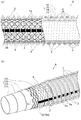
- the antistatic flexible tube A according to the embodiment of the present invention is manufactured in the food industry including beverages, the chemical industry including medical products, the semiconductor industry, the cosmetics industry, the fragrance industry, and other manufacturing. These are hoses and tubes used in factories. In particular, hoses and tubes that not only prevent static electricity generated during the transportation of powders and granules, but also have excellent pressure resistance. More specifically, the antistatic flexible tube A according to the embodiment of the present invention includes a flexible tube body 1, a conductive layer 2 provided axially along the outer peripheral surface 1a of the tube body 1, and a tube. A conductive wire 3 spirally provided along the outer peripheral surface 1a of the main body 1 and an outer surface 2a of the conductive layer 2 and a reinforcing member 4 spirally provided along the conductive wire 3 are provided as main components. ing.
- the tube body 1 is made of a soft synthetic resin such as vinyl chloride, a semi-hard synthetic resin, an elastomer thereof, or other soft or semi-hard material such as rubber, and is formed into a single-layer structure, a multi-layer structure, or a multi-layer structure. Will be done.
- a single-layer structure means a structure consisting of only a single layer
- a multi-layer structure means a structure in which a plurality of layers are laminated so as to overlap in the radial direction of the pipe body 1
- a multi-layer structure means a structure in which a large number of layers are overlapped. It refers to those laminated in the radial direction of the pipe body 1.
- the constituent material of the pipe body 1 it is preferable to use a transparent material or a translucent material so that the fluid (not shown) flowing through the internal flow path Ap of the pipe body 1 can be seen through from the outside of the pipe body 1.
- a method for manufacturing the tube body 1 it is preferable to form a layer by extrusion molding, co-extrusion molding or the like.
- the blade 5 is a reinforcing thread made of synthetic resin fibers such as polyester, nylon (registered trademark), and aramid, and is braided in a net-like or knit-like shape.
- a conductive layer 2 having electrical conductivity in a part in the circumferential direction of the pipe body 1 is formed in a band shape or a linear shape extending in the axial direction of the pipe body 1.
- the conductive layer 2 is formed in the pipe body 1 over the entire radial direction of the layer exposed on the outer peripheral surface 1a, or is partially formed only on the radial outer side of the layer exposed on the outer peripheral surface 1a.
- Examples of the shape of the conductive layer 2 include a continuous shape arranged over the entire axial length of the pipe body 1 and an intermittent shape arranged at intervals of a predetermined length in the axial direction of the pipe body 1.
- the circumference of the pipe body 1 is sufficiently transparent so that the fluid in the internal flow path Ap can be sufficiently seen through the transparent or translucent pipe body 1. It is preferable to narrow the width in the direction and to form a plurality or only one in the circumferential direction at predetermined intervals.
- a conductive material containing fine particles of a carbon material such as carbon black or good conductive fine particles such as metallic fine particles is extruded or co-extruded with respect to a synthetic resin as a base. It is preferable to do so.
- the method for manufacturing the conductive layer 2 it is possible to print a conductive material, or to fix a wire made of metal, a conductive thread, a conductive monofilament, or the like.
- a spiral conductive wire 3 is provided along the outer peripheral surface 1a of the tube body 1 and the outer surface 2a of the conductive layer 2.
- the conductive wire 3 is formed of a wire made of a metal such as stainless steel and a conductive material having electrical conductivity such as a conductive thread or a conductive monofilament, and is formed in a linear shape, and the outer peripheral surface 1a of the tube body 1 and the outer surface 2a of the conductive layer 2 are formed. It is wound so as to be tightened in the radial direction of the pipe body 1 toward.
- the conductive wire 3 is wound so as to be in pressure contact with the outer peripheral surface 1a of the tube body 1 and the outer surface 2a of the conductive layer 2 in the radial direction of the tube body 1.
- a metal wire or the like as a hard material having higher rigidity than the constituent material of the tube body 1.
- the conductive wire 3 is wound around the tube body 1 and the conductive layer 2 which have been extruded or co-extruded with a predetermined winding tension by a coil molding machine (not shown) or the like. It is preferable that the conductive wire 3 is continuously wound and molded with the elastic repulsive force remaining.
- a spiral reinforcing member 4 is provided along the conductive wire 3 so as to project from the outer peripheral surface 1a of the pipe body 1 and the outer surface 2a of the conductive layer 2.
- the conductive layer 2 is recessed and arranged between the outer peripheral surface 1a of the pipe body 1 and the reinforcing member 4 spirally projecting from the outer surface 2a of the conductive layer 2.
- the reinforcing member 4 is a soft synthetic resin or a semi-hard synthetic resin having excellent compatibility with the constituent material of the outer peripheral surface 1a of the pipe body 1 and easily adhering, or an elastomer of these or other soft or semi-hard material such as rubber.
- the constituent material of the reinforcing member 4 is a material harder than the soft material constituting the pipe body 1, and the fluid flowing through the internal flow path Ap of the pipe body 1 can be seen through from the outside of the pipe body 1 and the reinforcing member 4. As described above, it is preferable to use a transparent or translucent material. Further, the reinforcing member 4 is arranged so that the conductive wire 3 is sandwiched between the reinforcing member 4 and the outer surface 2a of the conductive layer 2 and the surface of the conductive wire 3 is pressed against the outer surface 2a of the conductive layer 2.
- the reinforcing member 4 As a method for manufacturing the reinforcing member 4, it is preferable to laminate the reinforcing member 4 on the pipe body 1 and the conductive layer 2 which are continuously formed in the axial direction by extrusion molding or co-extrusion so as to overlap the conductive wire 3. ..
- the conductive layer has a continuous shape over the entire axial length of the tube body 1 having a multi-layer structure. It forms layer 2.
- an inner layer 11 made of semi-hard vinyl chloride or the like having excellent wear resistance and transparent in the entire circumferential direction and a transparent outer layer 12 made of soft vinyl chloride or the like are laminated in the radial direction. It has a two-layer structure.
- a band-shaped conductive layer 2 is co-extruded and formed on a part of the outer layer 12 in the circumferential direction so as to be exposed on the outer peripheral surface 12a of the outer layer 12.
- the tube body 1 of the illustrated example has an innermost layer 13 made of a fluororesin (ethylene-tetrafluoroethylene copolymer) or the like having excellent wear resistance, gas permeability and chemical resistance, and a polyamide resin (modified nylon 12). ) And the like, and an intermediate layer 15 and an outer layer 16 made of a polyurethane-based elastomer (thermoplastic polyurethane) or the like are laminated in the radial direction to form a four-layer structure.
- a fluororesin ethylene-tetrafluoroethylene copolymer
- a polyamide resin modified nylon 12
- a band-shaped conductive layer 2 is co-extruded and formed on a part of the outer layer 16 in the circumferential direction so as to be exposed on the outer peripheral surface 16a of the outer layer 16.
- a net-like blade 5 is provided between the intermediate layer 15 and the outer layer 16 along the outer surface of the intermediate layer 15.
- the tube body 1 may be formed into a single-layer structure to form the conductive layer 2 on the entire radial direction or only on the outer side in the radial direction, or the tube body 1 may have a three-layer structure. It is possible to change to a structure with five or more layers.
- the shape of the conductive layer 2 is changed to an intermittent shape instead of a continuous shape, a net-like or knit-knit-like blade 5 is provided between the inner layer 11 and the outer layer 12 of the first embodiment, and the second embodiment. It is also possible to change the blade 5 of the above to a knitted knitted shape instead of the net shape.
- the shape of the conductive layer 2 is changed to an intermittent shape, it is arranged so as to straddle the pitches of the conductive wires 3.
- a method of using the antistatic flexible tube A according to the embodiment of the present invention will be described.
- a hose having a conductive wire exposed on the surface of the hose is fitted into a grounded metal pipe, and the connection between the metal pipe and the hose” described in Patent No. 3690790.
- a "hose connection structure” characterized in that a coiled metal ground member is fitted in the portion and the ground member is brought into contact with the metal pipe and the conductive wire on the surface of the hose. That is, instead of the "hose” described in Japanese Patent No.
- the antistatic flexible pipe A of the first embodiment and the second embodiment is charged to the metal pipe in a state of being grounded by grounding on the device main body side.
- the axial end of the preventive flexible tube A is fitted, and a metal ground member is attached to the connection portion between the metal pipe and the axial end of the antistatic flexible tube A and tightened with a coil portion.
- the outer surface 2a of the conductive layer 2 exposed between the spiral reinforcing members 4 on the surface of the antistatic flexible tube A and the metal pipe are kept in contact with each other, and the conductive layer 2 is kept in contact with the ground member. Is electrically connected to the metal pipe via the ground member, and the antistatic flexible tube A is in a grounded state.
- the static electricity generated in the antistatic flexible tube A is discharged via the conductive wire 3 ⁇ the conductive layer 2 ⁇ the ground member ⁇ the metal pipe ⁇ the main body of the device. Further, when the device main body side is not grounded, it is also possible to attach a metal grounding member to an arbitrary position in the axial direction of the antistatic flexible tube A and ground it by grounding.
- the internal flow path Ap is crushed and deformed into a substantially elliptical cross section as the flexible pipe is bent, and the fluid is easily clogged and maintained. Inferior in shape.
- the conductive layer 2 of the antistatic flexible tube A is arranged at the portion Ao (extension side) outside the bending direction in the bending portion as shown in FIG. 3A depending on the usage situation thereof.
- it may be arranged at the portion Ai (escape fold side) inside the bending direction.
- the first embodiment is shown. Since the second embodiment is the same as the first embodiment, it is omitted.
- the antistatic flexible tube A As shown in FIG. 3A, a force is applied so as to separate the conductive layer 2 from the reinforcing member 4 and the conductive wire 3 by bending the tube A. Even if it acts, since the conductive wire 3 is tightened in the radial direction toward the outer surface 2a of the conductive layer 2, the crimping state with the conductive wire 3 is maintained following the conductive layer 2. As a result, the contact resistance between the conductive layer 2 and the conductive wire 3 is kept low independently of the axial length of the antistatic flexible tube A.
- the conductive layer 2 is recessed between the outer peripheral surface 1a of the pipe body 1 and the reinforcing member 4 spirally projecting from the outer surface 2a of the conductive layer 2. Therefore, even if the reinforcing member 4 comes into contact with the ground contact surface or the like, the conductive layer 2 does not come into contact with each other. Further, even if the conductive wire 3 is covered with the reinforcing member 4 and is not exposed, and the reinforcing member 4 comes into contact with the ground plane or the like, the conductive wire 3 is not in contact.
- the conductive layer 2 does not come into direct contact with the ground surface or the like, so that vibration or impact on the conductive layer 2 may occur. It is also reduced and less likely to crack, break or peel off, and can be used with confidence in the food / beverage industry and medical industry, which are strict against foreign matter contamination. Further, since the conductive wire 3 is protected by the reinforcing member 4 and does not come into direct contact with the ground plane or the product, the conductive wire 3 is less likely to be damaged or peeled off, and the food / beverage industry, the medical industry, etc., which are strict against foreign matter contamination, etc. But you can use it with confidence.
- the conductive wire 3 is made of a metal such as a wire or a material that is easily rusted or oxidized such as a conductive thread, it is protected by the reinforcing member 4 and does not come into direct contact with a fluid or the like, so that rust or oxidation occurs. Can be prevented.
- the conductive wire 3 it is preferable to form the conductive wire 3 with a material harder than the constituent material of the tube body 1.
- the conductive wire 3 not only functions as a ground wire but also functions as a reinforcing material. Therefore, by using the hard conductive wire 3 and the reinforcing member 4 together, it is possible to reliably prevent the entire pipe from being crushed and deformed due to bending. As a result, the shape retention of the entire pipe can be improved.
- the "hose connection structure" described in Japanese Patent No. 3690790 is used as an example of using the antistatic flexible pipe A, but the present invention is not limited to this, and the ground member of Japanese Patent No. 3690790 is used. If the static charge can be removed at any part of the antistatic flexible tube A, such as by using a tightening band having another structure for which the installation location for the antistatic flexible tube A is not specified, other structures are used. May be used.
Landscapes
- Engineering & Computer Science (AREA)
- General Engineering & Computer Science (AREA)
- Mechanical Engineering (AREA)
- Rigid Pipes And Flexible Pipes (AREA)
Abstract
La présente invention empêche des augmentations de la résistance de contact d'une couche conductrice et d'un fil conducteur associées à la courbure d'un tube souple et empêche également l'endommagement et la séparation de la couche conductrice et du fil conducteur. L'invention concerne plus précisément un tube souple antistatique qui est caractérisé en ce qu'il comprend un corps de tube qui est formé à partir d'un matériau doux souple, une couche conductrice qui est disposée le long d'une surface circonférentielle externe du corps de tube dans la direction axiale, un fil conducteur qui est enroulé en hélice le long de la surface circonférentielle externe du corps de tube et une surface externe de la couche conductrice de façon à presser la surface circonférentielle externe du corps de tube et la surface externe de la couche conductrice dans la direction radiale, et un élément de renforcement qui est disposé de façon hélicoïdale le long du fil conducteur de façon à faire saillie à partir de la surface circonférentielle externe du corps de tube et de la surface externe de la couche conductrice, le fil conducteur étant pris en sandwich entre l'élément de renforcement et la surface extérieure de la couche conductrice de telle sorte que la surface du fil conducteur est pressée sur la surface extérieure de la couche conductrice.
Priority Applications (4)
| Application Number | Priority Date | Filing Date | Title |
|---|---|---|---|
| CN202080024413.7A CN113631847B (zh) | 2019-04-12 | 2020-04-10 | 防带电挠性管 |
| US17/601,573 US11859736B2 (en) | 2019-04-12 | 2020-04-10 | Antistatic flexible hose |
| MYPI2021005656A MY194506A (en) | 2019-04-12 | 2020-04-10 | Antistatic flexible hose |
| EP20787505.5A EP3954931B1 (fr) | 2019-04-12 | 2020-04-10 | Tuyau antistatique |
Applications Claiming Priority (2)
| Application Number | Priority Date | Filing Date | Title |
|---|---|---|---|
| JP2019076093A JP6757994B1 (ja) | 2019-04-12 | 2019-04-12 | 帯電防止可撓管 |
| JP2019-076093 | 2019-04-12 |
Publications (1)
| Publication Number | Publication Date |
|---|---|
| WO2020209352A1 true WO2020209352A1 (fr) | 2020-10-15 |
Family
ID=72517941
Family Applications (1)
| Application Number | Title | Priority Date | Filing Date |
|---|---|---|---|
| PCT/JP2020/016074 Ceased WO2020209352A1 (fr) | 2019-04-12 | 2020-04-10 | Tube souple antistatique |
Country Status (6)
| Country | Link |
|---|---|
| US (1) | US11859736B2 (fr) |
| EP (1) | EP3954931B1 (fr) |
| JP (1) | JP6757994B1 (fr) |
| CN (1) | CN113631847B (fr) |
| MY (1) | MY194506A (fr) |
| WO (1) | WO2020209352A1 (fr) |
Cited By (1)
| Publication number | Priority date | Publication date | Assignee | Title |
|---|---|---|---|---|
| WO2022084549A1 (fr) * | 2020-10-22 | 2022-04-28 | Truplast Kunststofftechnik Gmbh | Tuyau flexible, plus précisément tuyau d'aspirateur, son procédé de production et dispositif pouvant être utilisé à cet effet |
Families Citing this family (2)
| Publication number | Priority date | Publication date | Assignee | Title |
|---|---|---|---|---|
| KR102548394B1 (ko) * | 2021-08-31 | 2023-06-27 | (주)위온 | leak 감지 및 정전기 제거 플렉시블 튜브 |
| CN118441385B (zh) * | 2024-05-13 | 2026-01-02 | 盐城鑫业纺织有限公司 | 抗静电腈纶纱线及制作工艺 |
Citations (10)
| Publication number | Priority date | Publication date | Assignee | Title |
|---|---|---|---|---|
| JPS5176622A (fr) * | 1974-11-25 | 1976-07-02 | Suchuaado Purasuchitsukusu Inc | |
| JPS5442010U (fr) * | 1977-08-29 | 1979-03-20 | ||
| JPS63177377U (fr) * | 1987-05-07 | 1988-11-17 | ||
| JP2000065257A (ja) * | 1998-08-14 | 2000-03-03 | Toyox Co Ltd | ホース |
| US20040108011A1 (en) * | 2002-10-21 | 2004-06-10 | Karl Eck | Hose for a fuel feed device |
| JP3690790B2 (ja) | 2000-06-19 | 2005-08-31 | 株式会社トヨックス | ホース接続構造 |
| JP2010144808A (ja) * | 2008-12-17 | 2010-07-01 | Kanaflex Corporation | 可撓性耐圧・耐摩耗ホース |
| JP5368861B2 (ja) | 2009-04-13 | 2013-12-18 | 株式会社八興 | 帯電防止樹脂ホース |
| WO2017141901A1 (fr) * | 2016-02-19 | 2017-08-24 | 株式会社八興 | Tuyau souple en résine dissipant l'électricité statique |
| KR101965772B1 (ko) * | 2017-11-24 | 2019-04-04 | (주)신우에이엔티 | 대전 방지용 튜브 |
Family Cites Families (22)
| Publication number | Priority date | Publication date | Assignee | Title |
|---|---|---|---|---|
| JPH0416045Y2 (fr) * | 1987-11-16 | 1992-04-10 | ||
| JP3120163B2 (ja) * | 1992-07-22 | 2000-12-25 | 金尾 茂樹 | 導電線内装クリーナーホース |
| US6671162B1 (en) * | 2001-06-26 | 2003-12-30 | Dana Corporation | Hose with conductive fiber |
| FR2911381B1 (fr) * | 2007-01-11 | 2010-11-05 | Axon Cable Sa | Cable hybride |
| JP5326072B2 (ja) | 2007-08-22 | 2013-10-30 | 株式会社トヨックス | 静電気防止用可撓管及び放電用継手 |
| WO2012128736A1 (fr) * | 2011-03-24 | 2012-09-27 | Eric Carlson | Tuyau souple doté de conducteurs hélicoïdaux incorporés et procédé de réalisation associés |
| US20110168287A1 (en) * | 2007-09-25 | 2011-07-14 | Steward Plastics, Inc. | Flexible tubing with dual-level imbedded helical conductors and method of making |
| US8563863B2 (en) * | 2007-09-25 | 2013-10-22 | Eric Carlson | Flexible tubing with improved signal transmission and method of making |
| ITMI20080960A1 (it) * | 2008-05-23 | 2009-11-24 | Merlett Tecnoplastic | Tubo presentante una elevata resistenza alla usura atto a consentire la dissipazione delle correnti elettrostatiche. |
| US7735523B2 (en) * | 2008-10-14 | 2010-06-15 | Flexible Technologies, Inc. | Self-extending electrical hose |
| CN201391686Y (zh) * | 2009-04-09 | 2010-01-27 | 钱康华 | 一种锥形管 |
| JP5637363B2 (ja) * | 2010-07-23 | 2014-12-10 | 株式会社トヨックス | 補強ホース |
| EP2514478B1 (fr) * | 2011-04-21 | 2013-07-31 | Plastiflex Group | Tuyau plastique flexible et procédé de fabrication associé |
| ITMI20111211A1 (it) * | 2011-06-30 | 2012-12-31 | Merlett Tecnoplastic | Struttura di tubo antistatico. |
| DE102013106164A1 (de) * | 2013-06-13 | 2014-12-31 | NORRES Beteiligungs-GmbH | Kunststoffschlauch mit antistatischen/ableitfähigen Eigenschaften |
| UA115587C2 (uk) * | 2015-10-09 | 2017-11-27 | Олександр Миколайович Березін | Спіральношовний полімерний виріб із стільниковою стінкою (варіанти) та довгомірний порожнистий термопластичний профіль для його виробництва |
| DE102016103528B4 (de) * | 2016-02-29 | 2021-05-27 | Norres Schlauchtechnik Gmbh | Kunststoffschlauch mit Faserverstärkung |
| CN205919024U (zh) * | 2016-06-29 | 2017-02-01 | 中裕软管科技有限公司 | 一种抗静电输油软管 |
| EP3270025A1 (fr) * | 2016-07-14 | 2018-01-17 | Masterflex SE | Conduite en tuyaux flexibles destinee a transporter des milieux abrasifs et procede et dispositif destines a sa fabrication |
| EP3284993A1 (fr) * | 2016-08-16 | 2018-02-21 | Masterflex SE | Tuyaux flexible comprenant un materiel de detection integre |
| CN208431474U (zh) * | 2018-07-10 | 2019-01-25 | 潍坊德通塑料制品有限公司 | 一种钢丝增强管 |
| US10955072B2 (en) * | 2018-09-07 | 2021-03-23 | Contitech Usa, Inc. | Lightweight hoses |
-
2019
- 2019-04-12 JP JP2019076093A patent/JP6757994B1/ja active Active
-
2020
- 2020-04-10 WO PCT/JP2020/016074 patent/WO2020209352A1/fr not_active Ceased
- 2020-04-10 MY MYPI2021005656A patent/MY194506A/en unknown
- 2020-04-10 CN CN202080024413.7A patent/CN113631847B/zh active Active
- 2020-04-10 US US17/601,573 patent/US11859736B2/en active Active
- 2020-04-10 EP EP20787505.5A patent/EP3954931B1/fr active Active
Patent Citations (10)
| Publication number | Priority date | Publication date | Assignee | Title |
|---|---|---|---|---|
| JPS5176622A (fr) * | 1974-11-25 | 1976-07-02 | Suchuaado Purasuchitsukusu Inc | |
| JPS5442010U (fr) * | 1977-08-29 | 1979-03-20 | ||
| JPS63177377U (fr) * | 1987-05-07 | 1988-11-17 | ||
| JP2000065257A (ja) * | 1998-08-14 | 2000-03-03 | Toyox Co Ltd | ホース |
| JP3690790B2 (ja) | 2000-06-19 | 2005-08-31 | 株式会社トヨックス | ホース接続構造 |
| US20040108011A1 (en) * | 2002-10-21 | 2004-06-10 | Karl Eck | Hose for a fuel feed device |
| JP2010144808A (ja) * | 2008-12-17 | 2010-07-01 | Kanaflex Corporation | 可撓性耐圧・耐摩耗ホース |
| JP5368861B2 (ja) | 2009-04-13 | 2013-12-18 | 株式会社八興 | 帯電防止樹脂ホース |
| WO2017141901A1 (fr) * | 2016-02-19 | 2017-08-24 | 株式会社八興 | Tuyau souple en résine dissipant l'électricité statique |
| KR101965772B1 (ko) * | 2017-11-24 | 2019-04-04 | (주)신우에이엔티 | 대전 방지용 튜브 |
Non-Patent Citations (1)
| Title |
|---|
| See also references of EP3954931A4 |
Cited By (2)
| Publication number | Priority date | Publication date | Assignee | Title |
|---|---|---|---|---|
| WO2022084549A1 (fr) * | 2020-10-22 | 2022-04-28 | Truplast Kunststofftechnik Gmbh | Tuyau flexible, plus précisément tuyau d'aspirateur, son procédé de production et dispositif pouvant être utilisé à cet effet |
| CN116802423A (zh) * | 2020-10-22 | 2023-09-22 | 图柏拉斯艺术有限公司 | 柔性软管、特别是真空吸尘器软管以及其生产方法和可用于其的装置 |
Also Published As
| Publication number | Publication date |
|---|---|
| CN113631847A (zh) | 2021-11-09 |
| US20220205563A1 (en) | 2022-06-30 |
| EP3954931A4 (fr) | 2022-12-14 |
| JP6757994B1 (ja) | 2020-09-23 |
| CN113631847B (zh) | 2022-10-04 |
| JP2020172998A (ja) | 2020-10-22 |
| EP3954931A1 (fr) | 2022-02-16 |
| EP3954931B1 (fr) | 2024-09-04 |
| MY194506A (en) | 2022-11-30 |
| US11859736B2 (en) | 2024-01-02 |
Similar Documents
| Publication | Publication Date | Title |
|---|---|---|
| JP6757994B1 (ja) | 帯電防止可撓管 | |
| US7114526B2 (en) | Composite hose with a corrugated metal tube | |
| CN101896754B (zh) | 类金属软管 | |
| EP1287281B1 (fr) | Tuyau souple renforce par tresse metallique | |
| WO2001023794A1 (fr) | Procede de production de conduit flexible forme de plusieurs couches, comprenant une couche metallique barriere, et utilisation associee | |
| US20120222766A1 (en) | Flexible hose with wear indicator | |
| WO2010095569A1 (fr) | Tube multicouche résistant à la pression et son procédé de fabrication | |
| HK40055884A (en) | Antistatic flexible tube | |
| HK40055884B (en) | Antistatic flexible tube | |
| JP5326072B2 (ja) | 静電気防止用可撓管及び放電用継手 | |
| JP2009036225A (ja) | 管継手 | |
| CN113195953B (zh) | 挠性管 | |
| JP2009180312A (ja) | ホース口金具用樹脂製ニップル及びホース口金具接続構造 | |
| JP5993256B2 (ja) | 電気掃除機用ホース | |
| AU9588601A (en) | Protective sheath | |
| JP5897435B2 (ja) | 電気掃除機用ホース | |
| EP3660379B1 (fr) | Stucture de connexion d'un tuyau multicouche, en particulier pour les fluides chimiques et alimentaires | |
| JP4649630B2 (ja) | シリコーン補強ホース | |
| JP7495024B2 (ja) | 特に化学流体および食品関連流体用の多層管 | |
| JP5626774B2 (ja) | 合成樹脂管 | |
| JP5993257B2 (ja) | 電気掃除機用ホース | |
| JP5946660B2 (ja) | 可撓性ホース | |
| JP2016160948A (ja) | 可撓性ホース | |
| CN117386898A (zh) | 一种复合型多功能软管 | |
| JP2000266245A (ja) | 合成樹脂製ホース |
Legal Events
| Date | Code | Title | Description |
|---|---|---|---|
| 121 | Ep: the epo has been informed by wipo that ep was designated in this application |
Ref document number: 20787505 Country of ref document: EP Kind code of ref document: A1 |
|
| NENP | Non-entry into the national phase |
Ref country code: DE |
|
| ENP | Entry into the national phase |
Ref document number: 2020787505 Country of ref document: EP Effective date: 20211112 |